

Page 1
JD-5000(LX-171)
INDEX
JUL. 1993
(without price)
JD-5000(BU)
R
Page 2

CONTENTS
1. SCHEMATIC DIAGRAM................................................................................................ 1
2. SPECIFICATIONS ......................................................................................................... 3
3. LSI PIN FUNCTION....................................................................................................... 4
4. OPERATION CHECK .................................................................................................... 7
5. TO SAVE THE DATA TO OTHER MACHINE............................................................... 8
6. EXPLODED VIEW ....................................................................................................... 11
7. PARTS LIST ................................................................................................................ 13
Page 3
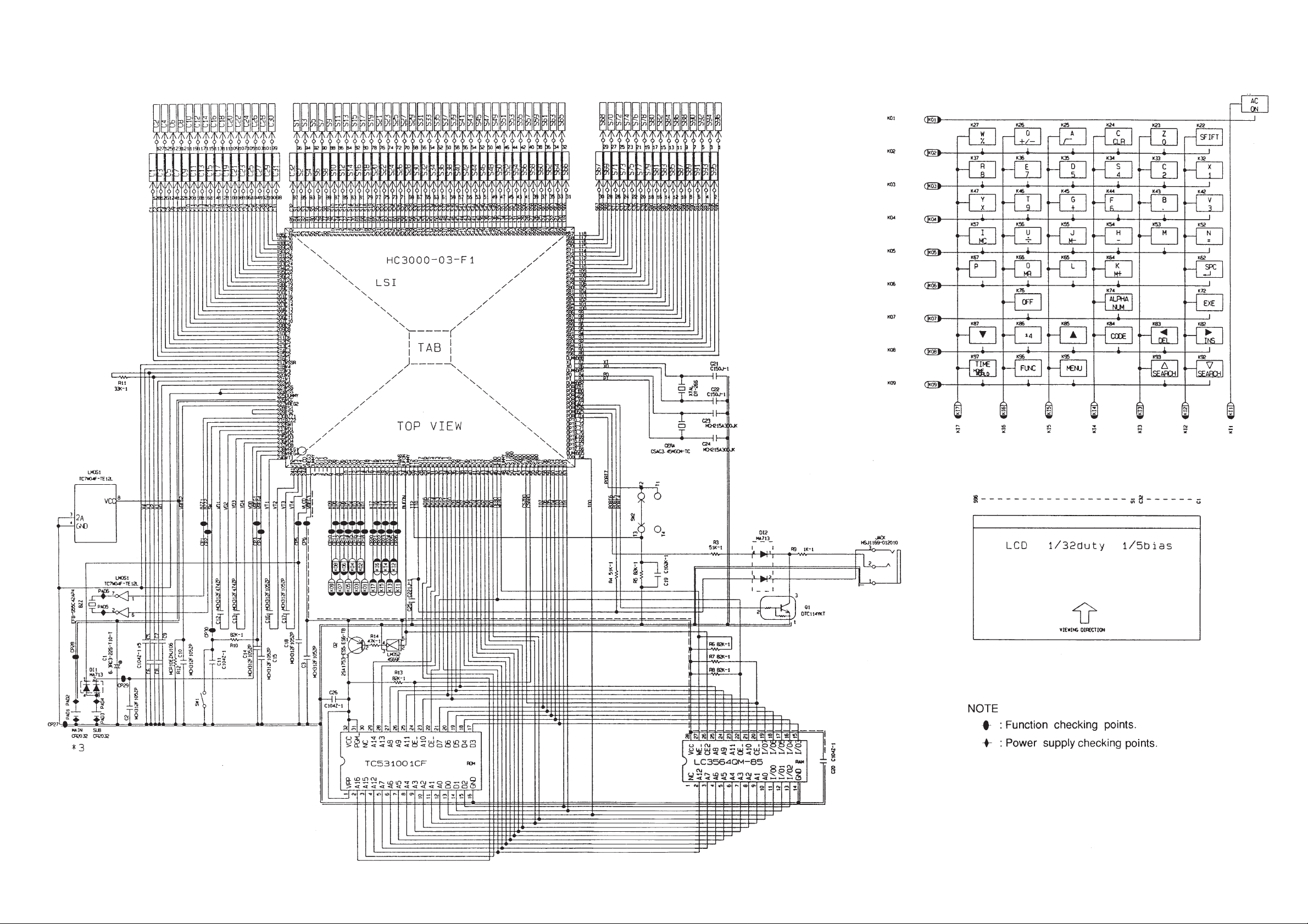
1. SCHEMATIC DIAGRAM
— 1 —
Page 4

2. SPECIFICATIONS
Display: Liquid crystal display
Memory Capacity: 6,144 bytes
Power Supply: Two lithium batteries (CR2032) ... Main and Back-up
Power Consumption: 0.05W
Battery Life: Main battery: Approximately 7,000 hours (1 hour use per
day)
Back-up battery: Approximately 3 years after the low main
battery warning appears on the display
Auto Power Off: Approximately 6 minutes after last key operation
Ambient Temperature
Range: 0°C ~ 40°C (32°F ~ 104°F)
Dimensions: Open: 9.3(H) × 145(W) × 163(D) mm
3
(
/8"(H) × 5 3/4"(W) × 6 3/8"(D))
Closed: 13.9(H) × 145(W) × 84(D) mm
1
(
/2"(H) × 5 3/4 "(W) × 3 1/4"(D))
Weight: 112 g(4 oz) including batteries
— 3 —
Page 5

3. LSI PIN FUNCTION
1. CPU (HC3000-03-F1)
Pin No. Signal In/Out Function
1 VREG3 Out Power supply for RAM / 3(V)
2 DMY – Not used
3 ~ 5 KO10 ~ 12 Out Not used
6 ~ 14 KO1 ~ 9 Out Key scan signal
15 KI8 In Not used
16 ~ 22 KI1~7 In Key input signal
23 , 25 TRANS, DUMMY – Not used
24 DUFON Out Power supply control for ROM
26 IT2 In Battery switch position sensor
27 IT0 In Reception data input
28 AO17 Out Not used
29 ~ 45 A0 ~ A16 Out Address bus
46 OEB0 Out Output enable signal for RAM and ROM
47 WEB0 Out Write enable signal for RAM
48 ~ 52 – Not used
53 CS7B0 Out Chip enable signal for RAM
54 CS6 Out Chip enable signal for ROM
55, 56 Out Not used
57 ~ 64 IO0 ~ IO7 In/Out Data bus
65 ~ 73 – Not used
74 PORT7 – Battery switch on: "L" / 0[V]
off: "H" / 5[V]
— 4 —
Page 6

Pin No. Signal In/Out Function
75 ~ 77 PORT4~6 I/O For data communication
78 ~ 82 – Not used
83, 84 PI, PO In/Out Main clock terminal
85 DUMMY – Not used
86, 87 XI, XO In/Out Clock terminal
88 DUMMY – Not used
89 ~ 184 S1 ~ S96 Out Segment signal for display
185 ~ 216 C1 ~ C32 Out Common signal for display
217 VSSR In GND / 0[V]
218 ~ 222 V0 ~ V4 Out The voltage for LCD drive
OFF : 0[V]
ON; V0 : 3.6 (Min) ~ 5.8 (Max) [V]
V1 : 2.9 (Min) ~ 4.6 (Max) [V]
V2 : 2.1 (Min) ~ 3.5 (Max) [V]
V3 : 1.4 (Min) ~ 2.5 (Max) [V]
V4 : 0.7 (Min) ~ 1.3 (Max) [V]
223, 224 VSS In GND / 0[V]
225 DUMMY – Not used
226 VCC In Power supply / 3[V]
227 VREG2 Out 2 [V]
228, 229 TS1, 2 – Test for manufacture
230, 231 BZ1, 2 Out Buzzer terminal
232 SW1 In 2.6[V]
While pushing the reset button: 0[V]
233, 234 VD1, 2 – VD1: 4.7[V] VD2: 1.5[V]
235, 236 VD3, 4 – VD3: 4.7[V] VD4: 1.5[V]
— 5 —
Page 7

Pin No. Signal In/Out Function
237 VDB In Low battery detection
VDB < 4.4[V] ⇒ Low battery message
238, 239 VREG1, 4 – VREG1: 2.6 [V]
VREG4: 5.0 [V]
240 ~ 243 VT1 ~ VT4 – VT1 : 1.0[V] VT2 : 2.9[V]
VT3 : 2.0[V] VT4 : 3.9[V]
244 VLCD Out 5.8 [V]
2. RAM (LC3564QM-85)
Pin No. Signal In/Out Function
1 ~ 10 A0~A7, A12, A14 In Address bus
11 ~ 13 I/O 0 ~ I/O 2 In/Out Data bus
14 GND In GND / 0[V]
15 ~ 19 I/O 3 ~ I/O 7 In/Out Data bus
20 CE In Chip enable signal
21 A10 In Address bus
22 OE In Output enable signal
23 ~ 26 A8, A9, A11, A13 In Address bus
27 WE In Write enable signal
28 VCC In Power supply / 3[V]
— 6 —
Page 8
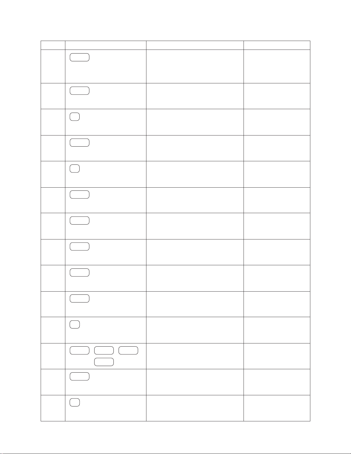
4. OPERATION CHECK
STEP OPERATION DISPLAY NOTE
1
MENU
Then short in the check pad
about two seconds.
Caution!
This is TEST
To Escape
Press AC KEY
The check pad is
located left side of the
battery switch.
2
3
4
5
6
7
8
EXE
1
EXE
2
EXE
EXE
EXE
1. RAM 2. DISP
3. KEY 4. TRANS
5. RESET 6. FCC
To Esc Press AC
RAM OK!
1. RAM 2. DISP
3. KEY 4. TRANS
5. RESET 6. FCC
All dots display
No display
Checker display
Reverse checker display
RAM check
DISPLAY check
9
10
11
12
13
14
✽ CAUTION : If customer's data are stored in the unit, all data will be corrupted by this operation.
EXE
EXE
3
MENU
· · · · · · · SHIFT
EXE
5
TIME
FUNC
Frame display
1. RAM 2. DISP
3. KEY 4. TRANS
5. RESET 6. FCC
MENU
TIME, FUNC, · · · , SHIFT
1. RAM 2. DISP
3. KEY 4. TRANS
5. RESET 6. FCC
RESET!
Key check
Push the key sequertially
appeared on the display.
Check the key sound.
After a half second, the
main menu will appear.
— 7 —
Page 9

5. TO SAVE THE DATA TO OTHER MACHINE
CASIO's SB-62 Data Communication Cable is available as an option. You can use this to connect My Magic
Diary to another My Magic Diary unit, or to a CASIO SF-A10, SF-A20, or SF-A30. Data can be shared among
all of these products.
Basic hardware set up for data communication:
1. Switch off the power of both the sending and receiving units.
2. Remove the connector covers of both units.
3. Connect the two units with a CASIO SB-62 Data Communication Cable. Be sure to insert the connectors
at the ends of the cable securely into the units.
4. Switch on the power of both sending and receiving units.
To prepare one unit to receive:
1. On the unit intended for reception, while in the main menu or a data display, press FUNCTION . Then use
to highlight "Communication." Press EXE.
2. Use the or to highlight "Receive Data." Press EXE.
Sending Data for a Specific Mode
You can send either a single data item (the smallest packet of data which can be sent in the Calendar Mode,
for example, is a single month), or all the data items stored in a specific mode. Different procedures are used
to send all the data in a mode, depending on whether you start from within that mode, or from the main menu.
To send one data item:
1. Enter the mode that contains the data; then search for and display the data you wish to send.
2. Press FUNCTION. Then use to highlight "Communication." Press EXE.
3. Use to highlight "Send Data." Press EXE.
4. Use to highlight "1 Data." Press EXE.
S e n d O K ?
Y e s / No
5. Use to highlight "Yes." Then press EXE. This begins data transfer to the receiving unit.
To send all the data in a mode, starting from within that mode:
1. Enter the mode that contains the data you want to send. Then press or to display the data for that
mode.
2. Press FUNCTION. Then use to highlight "Communication." Press EXE.
3. Use to highlight "Send Data." Press EXE.
4. Use and to highlight "Mode Data." Press EXE.
5. Use to highlight "Yes." Then press EXE. This begins data transfer to the receiving unit.
6. After the transmission has been completed, the data display for the item sent will appear on screen.
N o
— 8 —
Page 10

To send all the data in a mode, starting from the main menu:
1. Start from the main menu.
2. Press FUNCTION. Then use to highlight "Communication." Press EXE.
3. Use to highlight "Send Data." Press EXE.
4. Use to highlight "Mode Data." Press EXE.
5. Use and to select the name of the mode from which data you wish to send. Press EXE.
6. Use to highlight "Yes." Then press EXE. This begins data transfer to the receiving unit.
7. After the transmission has been completed, the main menu will reappear.
Sending All Data
Important!
The following procedure sends either all Open Memory Area data or all Secret Memory Area data. Before
starting to transmit, be sure to access the memory area (Open or Secret) which contains data you wish to send.
To send all data:
1. Begin from either the main menu or from a data display (Telephone Directry, Schedule, Data Memo "Diary",
or Calendar).
2. Press FUNCTION. Then use to highlight "Communication." Press EXE.
3. Use to highlight "Send Data." Press EXE.
4. Use to highlight "All Data." Press EXE.
5. Use to highlight "Yes." Then press EXE. This begins data transfer to the receiving unit.
6. After the transmission has been completed, the display you started from will reappear.
About the "Set up" Menu Item
You will probably notice that the menu appears on the display after you select "Communication" from the
function menu and press EXE. The "Set up" item contained in that menu is used for setting the parameters
of the My Magic Diary. Note, that the parameters should always be set to "None" (Parity) and "9600" (BPS)
for data communications between two units.
— 9 —
Page 11

Features and Functions
Telephone Directory Mode
B
Use this to keep names, phone numbers, and addresses. There are two storage areas, so you
can keep school and personal data separate. You can also include fun faces of the people whose
names and addresses you keep.
P
Schedule Mode
Stores the date, time, and type of each appointment. You can select icons to indicate each
appointment at a glance.
Calendar Mode
Displays the calendar for any month from January, 1901, to December, 2099. You can specify
holidays for highlighting.
Data Memo "Diary" Mode
Stores notes and special thoughts. Diary entry consists of a memo name and the memo's
contents.
Secret Memory Area
Stores your private thoughts you wish to keep confidential. No one can gain access to the Secret
Memory Area without knowing your password.
Timekeeping Mode
Home Time displays the current time where you are. World Time shows the time in any of 29 zones around
the globe. You can use 24-hour or 12-hour format, and can even specify daylight savings time.
Alarm Mode
Lets you set alarms to the minute, for alarms to go off every hour, or for a single time each day.
You can also set the Schedule Alarm and control the key input tone.
Fortune Telling Mode
Once you have entered your birthday, you can check your fortune today, or for any day. Have fun
telling your friend's fortune too.
Match Maker Mode
Tells you whether or not you are compatible with that special someone.
Conversion Mode
Helps you compare US dollar values against six foreign currencies (monies), or with combinations
of currency units.
Calculator Mode
A 10-digit calculator performs most common numerical operations including percents, square
roots and memory.
— 10 —
Page 12

6. EXPLDED VIEW
— 11 —
Page 13

7. PARTS LIST
— 13 —
Page 14

— 14 —
Page 15

8-11-10, Nishi-Shinjuku
Shinjuku-ku, Tokyo 160, Japan
Telephone: 03-3347-4926
 Loading...