

Page 1
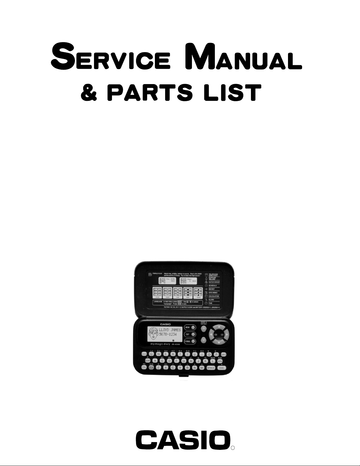
JD-4000BK(ZX-805A)
INDEX
DEC. 1994
(without price)
JD-4000BK
R
Page 2

CONTENTS
1. SCHEMATIC DIAGRAM................................................................................................ 1
2. SPECIFICATIONS ......................................................................................................... 3
3. GENERAL GUIDE ......................................................................................................... 6
4. RESET OPERATIONS .................................................................................................. 9
5. BATTERY REPLACEMENT........................................................................................ 11
6. ERROR MESSAGE ..................................................................................................... 13
7. LSI PIN FUNCTION ..................................................................................................... 14
8. OPERATION CHECK .................................................................................................. 16
9. TO SAVE THE DATA TO ANOTHER MACHINE........................................................ 17
10. TROUBLESHOOTING................................................................................................. 20
11. EXPLODED VIEW ....................................................................................................... 23
12. PARTS LIST ................................................................................................................ 25
Page 3
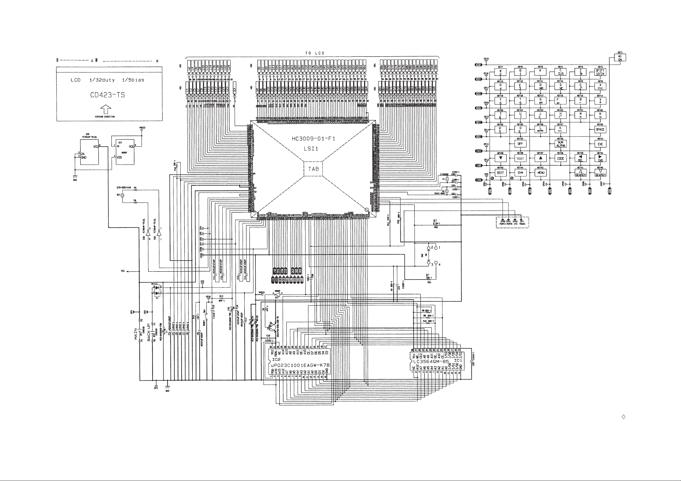
1. SCHEMATIC DIAGRAM
— 1 —
NOTES:
1. DP1, DP2, and DP3 are the checking
points for the power supply.
2. CP50, CP51, CP52, and DP1 are the
terminals for the data transfer.
3. The other terminals marked with
may be used to function checking.
4. R50 and R51 are not used.
Page 4

2. SPECIFICATIONS
Telephone Directory Mode
Storage and recall of telephone directory data (name, telephone number, portrait). Includes secret
memory area and auto sort function.
Schedule Mode
Storage and recall of appointments (month/date/hour/minute, description). Includes secret memory
area and auto sort function.
Data Memo Mode
Storage and recall of memos (memo name, memo). Includes secret memory area and auto sort
function.
Timekeeping Mode
Average of accuracy ±3 seconds per day under normal temperatures: year/month/date, hour/minute/
second, AM/PM, day of the week, full automatic calendar, 12/24 hour timekeeping format
Alarm Mode
Daily Alarm (20-second electronic buzzer); Hourly Time Signal (beeps every hour on the hour)
Fortune Telling Mode
Fortune telling on any date from January 1, 1901 to December 31, 2099.
Match Maker Mode
Compatibility of any two people whose birthdays are from January 1, 1901 to December 31, 2099.
Calculator Mode
10-digit arithmetic calculations; constant calculations; memory calculations; 20-digit approximations;
percentage calculations; square roots; sign changes; function command signs
Triple Play Mode
Other functions
Contrast adjustment
— 3 —
Page 5
General
Display: Liquid crystal display
Memory Capacity: 4,096 bytes
Power Supply: Main batteries – One lithium battery (CR2032)
Back-up battery – One lithium battery (CR2032)
Power Consumption: 0.03 W
Battery Life*: Main batteries –
• approximately 400 hours continuous operation
• approximately 1 year (1 hour use per day)
Back-up battery – approximately 5 years after the low main battery
warning appears on the display
* The batteries which have been installed in this unit when you purchase it
are for the factory test, so that it will not be possible to satisfy the above
specifications when these batteries are used.
Auto Power Off: Approximately 6 minutes after last key operation
Ambient Temperature
Range: 0°C ~ 40°C (32°F ~ 104°F)
Dimensions: Open: 9.3 (H) × 146 (W) × 162.5 (D) mm
(3/8" (H) × 5 3/4" (W) × 6 3/8" (D))
Closed: 14.9 (H) × 146 (W) × 84.5 (D) mm
(5/8" (H) × 5 3/4 " (W) × 3 3/8" (D))
Weight: 138.2 g (4.9 oz) including batteries
Current consumption
Check point TYP [µA] Max [µA]
OFF CP1 - CP3 — 8.5
ON (Menu) CP1 - CP3 185 220
ON (Buzzer) CP1 - CP3 — 5000
How memory capacity is calculated
There is no limit on the amount of memory you can use in each mode, but the limit on the total
amount of data stored is 4,096 bytes. The following shows how many bytes the data in each mode
takes up. One character takes up one byte.
— 4 —
Page 6
Mode Bytes per Data Item
Telephone Directory (name) + (telephone number) + 15
Schedule (description) + 12
Data Memo (memo name) + (memo contents) + 3
Examples:
Telephone Directory data only
When all items use 10 characters for the name and 12 characters for the phone number, you
can store approximately 110 items.
Schedule data only
When all items use 20 characters, you can store approximately 120 items.
Data Memo data only
When all items use 10 characters for the memo name and 10 characters for the memo
content, you can store approximately 170 items.
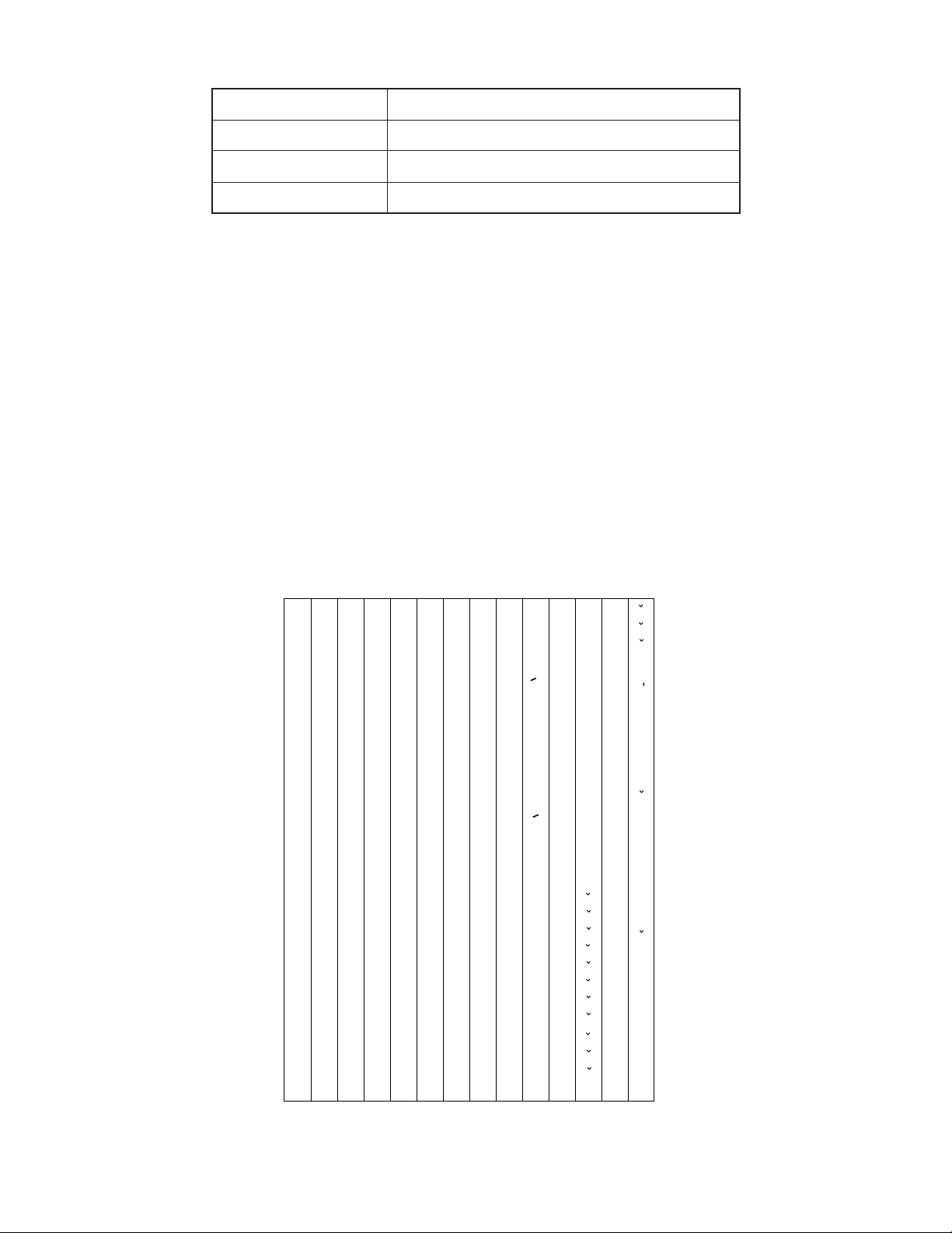
Sort Sequence
The following table shows the sequence used for sorting data in the Telephone Directory and the Data
Memo Modes.
1
2
3
4
5
6
7
8
9
10
11
12
13
14
15
16
17
18
19
20
21
22
23
24
25
26
27
28
29
§
→
←
÷
×
Space
!
”
#
$
%
&
’
(
)
∗
+
,
–
•
/
0
1
2
3
4
5
6
7
30
31
32
33
34
35
36
37
38
39
40
41
42
43
44
45
46
47
48
49
50
51
52
53
54
55
56
57
58
@
"
o
146
Ì
117
t
88
V
59
8
Â
147
Ò
118
u
89
W
60
9
Ê
148
Ù
119
v
90
X
61
:
Î
149
Ç
120
w
91
Y
62
;
Ô
150
L
121
x
92
Z
63
<
y
93
„
64
>
z
94
¥
65
?
“
66
¡
67
A
¿
68
B
a
69
C
b
70
D
c
71
E
d
72
F
e
73
G
f
74
H
g
75
I
h
76
J
i
77
K
j
78
L
k
79
M
l
80
N
m
81
O
n
82
P
o
83
Q
p
84
R
q
85
S
r
86
T
s
87
U
95
96
97
98
99
100
101
102
103
104
105
106
107
108
109
110
111
112
113
114
115
116
<
<
£
>
>
~
Á
É
Í
Ó
Ú
Ã
Õ
Ñ
á
é
í
ó
ú
ã
õ
ñ
À
È
122
123
124
125
126
127
128
129
130
131
132
133
134
135
136
137
138
139
140
141
142
143
144
145
Ä
Ë
Ö
Ü
Æ
Œ
O
æ
œ
.
Z
à
è
ì
ò
ù
ç
l
.
z
Ï
"
ä
ë
ï
ö
ü
151
152
153
154
155
156
157
158
159
160
161
162
163
164
165
166
167
168
169
170
171
172
173
174
Û
Å
.
U
"
U
â
ê
î
ô
û
å
.
u
"
u
A
E
C
D
N
R
S
T
a
e
c
d'
175
176
177
178
179
180
181
182
183
184
185
186
187
188
189
190
191
192
193
194
195
196
197
n
r
s
t'
A
E
`
´
C
´
N
´
S
´
Y
´
Z
Z
a
`
e
`
c
´
n
´
s
´
y
´
z
´
z
Ø
ø
ß
— 5 —
Page 7
3.GENERAL GUIDE
Very important stuff! Here's where we tell you how not to lose important data stored in memory. Also,
be sure to perform the all-reset operation before using the JD-4000BK for the first time. The all-reset
operation is described in section 4.
Please be sure you understand the following before using the JD-4000BK.
Make back-up copies of important data!
The electronic memory in the JD-4000BK store and recall information quickly and easily. But that
information is retained only as long as power is supplied by the batteries. Should the batteries go
dead, or should you remove both batteries at the same time, data stored in memory can be lost
entirely. Data can also be corrupted or lost due to a strong electrostatic charge, strong impact, or
extremes in temperature and humidity. All of this means that you should always keep written back-up
copies of important data.
General Precautions
Warning!
• Never expose the unit or batteries to direct heat or flame.
• Avoid use or storage in very low temperatures. This may cause display response to slow down or
fail entirely. Very low temperatures can also shorten battery life.
• Avoid use or storage in very high temperatures. Even prolonged exposure to direct sunlight can
damage the unit. Leaving it on the dashboard of a closed car, or on a heater, is even worse.
• Avoid using or storing the unit where there is high humidity or a lot of dust. Never allow liquids to
come into contact with the unit.
• Avoid dropping the unit or otherwise subjecting it to strong impact.
• Never bend or twist the unit. Carrying it in your back pocket, for instance, can subject the unit to
abnormal bending and twisting.
• Never try to take the unit apart.
• Do not press the unit's keys with a pen, pencil, or other sharp object.
• To clean the unit, wipe it with a soft cloth. When necessary, you may wipe the exterior with a soft
cloth that has been dipped in a weak solution of a mild, neutral detergent and water.
• Never use strong liquid cleaners such as lacquer thinner or benzine to clean the unit.
• In no event will CASIO or its suppliers be liable to you or any other person for any damages,
including any incidental or consequential expenses, lost profits, lost savings, or any other damages arising out of the use of this product.
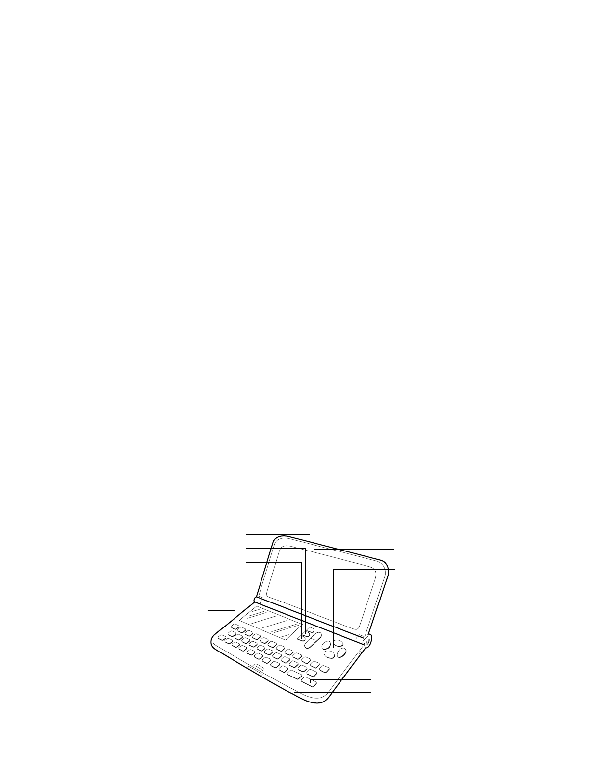
MENU Key
SYMBOL Key
Display
CODE Key
Clear Key
AC/ON Key
SHIFT Key
EDIT Key
SEARCH and CONTRAST Key
Cursor Keys
OFF Key
EXE Key
SPACE/Return Key
— 6 —
Page 8
Displaying the Main Menues
There is a total of three icon menues which are named by MENU 1, MENU 2, and MENU 3. An icon
menu will appear on the display once the switch is turned on, and the other icon menues can be
selected by using the MENU key.
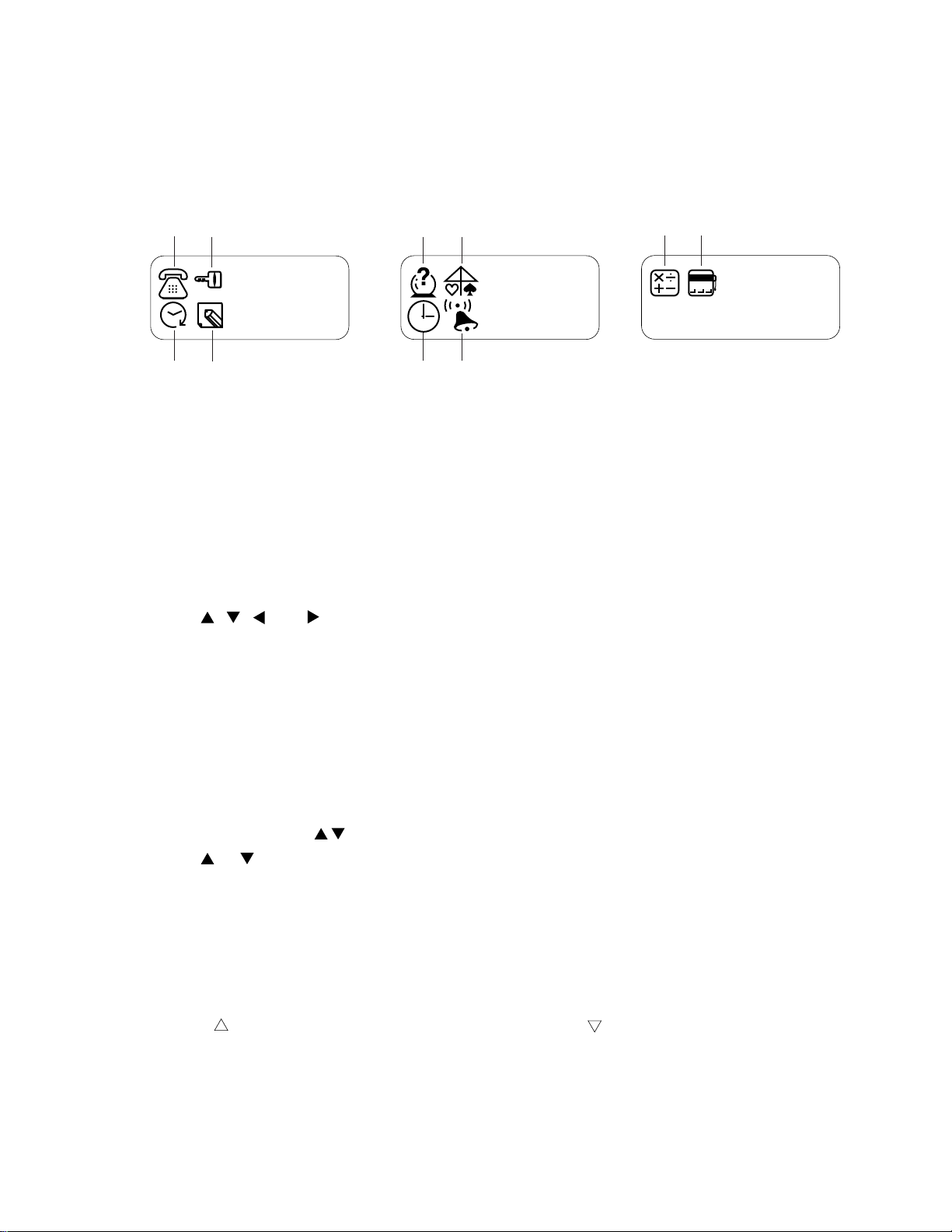
Icon menues
12
34
MENU 1
56
MENU 2
78
90
777
MENU 3
1 Telephone Directory Mode 6 Match Maker Mode
2 Secret Memory Area 7 Timekeeping Mode
3 Schedule Mode 8 Alarm Mode
4 Data Memo Mode 9 Calculator Mode
5 Fortune Telling Mode 0 Triple Play Mode
To Change Modes:
1. Press MENU to display the one of the menues, MENU 1, MENU 2, and MENU 3, that contains
the mode you want.
2. Use , , , and to move the highlight to the icon of the mode you want.
3. While the icon you want is highlighted, press EXE to enter its mode.
Setting the System Language
The JD-4000BK can display messages in any one of five languages: English, Spanish, Italian,
German, and French.
To set the system language
1. Press MENU to display any menu (MENU 1, MENU 2, or MENU 3).
2. Press EDIT and the " Language" appears on the screen.
3. Use or to select the language which you want to use.
* If you want to cancel this operation, press AC/ON.
4. Under the language you want being on the display, press EXE.
* After a few moments, the MENU from which you started out will reappear on the display.
To Adjust the Display Contrast
1. Press MENU to display a menu (MENU 1, MENU 2, or MENU 3).
2. Press to increase contrast (making the figures darker) or to decrease contrast (making the
figures lighter).
— 7 —
Page 9

To Switch the Key Input Tone On or Off
1. Press MENU to display MENU 2.
2. Use , , , and to highlight , and then press EXE to enter the Alarm Mode.
3. While the currect alarm time setting is shown, press e (C) to display the "Key Tone".
4. Use or to select the "ON" (key input tone on) or the "OFF" (key input tone off).
5. Press EXE to return to the current alarm time setting screen.
6. Press MENU to return to MENU 2.
Auto Power Off Function
This function automatically switches off the power if you do not touch any key of the unit for about six
minutes.
Pressing AC/ON can restore the power.
Features and Functions
Telephone Directory Mode
Store the names and phone numbers of your friends, along with their portraits.
Schedule Mode
Keep track of your promises and appointments.
777
Data Memo Mode
Store short memos and reminders.
Secret Memory Area
Keep your data private.
Timekeeping Mode
A built-in clock shows the current time.
Alarm Mode
An alarm sounds each day at the time you preset.
Fortune Telling Mode
Find out the fortunes of all your friends.
Match Maker Mode
Check how well two people are matched.
Triple Play Mode
An exciting game you can play alone or with a friend.
Calculator Mode
A 10-digit calculator.
— 8 —
Page 10

4. RESET OPERATIONS
Use the following operation to reset the unit and clear its memory.
Important!
• Be sure to reset the unit before using it for the first time.
• Do not use a very sharp pencil to press the RESET button. Doing so can damage the unit.
To reset the unit
1. Press AC/ON to switch power on.
2. Loosen the screw that holds the back-up battery compartment cover in place, and remove the
cover.
3. Use a thin, pointed object (like a paper clip) to press the RESET button inside the battery compartment cover. When you do, the "Reset?" screen should appear.
4. Press to select "Yes, " and then press EXE.
• MENU 1 appears on the display after all data is deleted.
5. Use the Timekeeping Mode to set the time after performing the RESET operation.
6. Replace the battery compartment cover.
• To abort the RESET operation, press to select "No" and then press EXE. This causes the
"Check time!" message to appear. Press EXE to display the time. If the time setting is wrong, use
the Timekeeping Mode to reset it.
• The following table shows what happens to all settings when you reset the unit.
RESET button
Memory Data All Cleared
Data All cleared
Current Date January 1, 1990
Current Time Midnight (12:00 AM)
Time Format 12-hour
Alarms All off
Alarm Time Midnight (12:00 AM)
Password Cleared
Secret Memory Area Cleared
System Language English
— 9 —
Page 11

When the unit does not work properly ...
The unit may stop working properly after it is subjected to strong electrostatic charge or strong
impact. If this happens, first check to make sure that the main battery and back-up battery are correctly installed, and then perform the following operation.
1. Loosen the screw that holds the battery compartment cover in place, and remove the cover.
2. Use a thin, pointed object (like a paper clip) to press the RESET button inside the battery compartment cover. When you do, the "Reset?" screen should appear.
3. Make sure that the pointer is located at "No," and then press EXE. The "Check time!" message
should appear on the display.
4. Press EXE again, and then use the Timekeeping Mode to set the current time.
5. Replace the battery compartment cover.
— 10 —
Page 12

5. BATTERY REPLACEMENT
Low Battery Warning
The message, "Low battery" appears whenever battery power drops below a certain level (about
2.70 V). Replace the main battery immediately after this message appears.
Whenever the low battery warning message appears, the OFF key will be the only function that
works. If you don't turn the unit off yourself, power will switch off automatically about 30 seconds after
the low battery warning appears.
Replacing Batteries
• Main Battery
One CR2032 lithium battery is used for the main power supply. The unit will not operate at all if
main battery is not installed.
• Back-up Battery
One CR2032 lithium battery supplies power to the memory and protects its contents.
Memory contents are lost when both the main battery and the back-up battery are removed. Be sure
always to leave one of the batteries in place to protect memory contents. If, however, you remove the
main battery for any time, memory retention will depend entirely on the condition of the back-up
battery. Over a long period of time with just the back-up battery in place, memory contents are likely
to be damaged. If memory seems corrupted, clear it using the RESET procedure described in section
4.
Important!
Incorrect use of batteries can cause them to burst or leak, possibly damaging the interior of the unit.
Note the following precautions:
• Be sure that the positive (+) and negative (–) poles of the batteries are facing in the proper direction.
• Never leave dead batteries in the battery compartment.
• Remove the batteries if you do not plan to use the unit for a long period of time.
• To avoid damage to the unit from leaky batteries, replace the batteries at least once every five
years, no matter how much you use the unit during that time.
Warning!
• Never try to recharge the batteries that come with the unit.
• Do not expose batteries to direct heat, short-circuit them, or try to take them apart.
• Keep batteries out of the reach of small children. If swallowed, consult a physician immediately.
— 11 —
Page 13

To replace the main battery
1. Switch power off.
2. Loosen the screw that holds the battery compartment cover in place, and then remove the
cover(Fig. 1).
* Do not turn switch on until you complete step 7 of this procedure.
3. Slide the tab in the direction indicated by the arrow (Fig. 2).
4. Insert a thin, pointed non-metallic object into the opening (A) so that the old battery can be removed (Fig. 3).
* Do not slide the tab while battery is not installed!
5. Wipe a new battery with a soft, dry cloth, then install the battery into the unit. Make sure that its
positive (+) side is facing up (so you can see this side).
6. Slide the tab back to the origin.
7. Replace the battery compartment cover and fix it with its screw.
Tab
Battery compartment
cover
Figure 1 Figure 2 Figure 3
To replace the back-up battery
1. Switch power off.
2. Loosen the screw that holds the battery compartment
cover in place, and then remove the cover (Fig. 1).
* Do not turn switch on until you complete step 7 of
this procedure.
3. Remove the back-up battery precaution sticker, and
then loosen the screw that holds the back-up battery
cover in place.
4. Remove the back-up battery cover and then remove
the old battery (Fig. 4).
5. Wipe a new battery with a soft, dry cloth, then install
the battery into the unit. Make sure that its positive
(+) side is facing up (so you can see this side).
6. Replace the back-up battery cover and fix it with its
screw. Do not forget to replace the battery precaution
sticker.
7. Replace the battery compartment cover and fix it with
its screw.
Main battery
Opening (A)
Back-up battery
Figure 4
Back-up battery cover
— 12 —
Page 14

6. ERROR MESSAGE
Message
Check Time!
Memory Full!
No Record!
Not Found!
Mismatch!
Low Battery
Meaning
Always appears when RESET
operation is aborted.
Memory is full.
No data stored in memory.
No data in memory matches data
specified for search.
Registered password does not
match input.
Battery power is low.
Action
Confirm that the current time
setting is correct.
Reduce number of characters
in data being stored, or delete
unneeded data from memory.
Store data before attempting
search operation.
Change specification.
Use correct password.
Replace the main battery.
— 13 —
Page 15

7. LSI PIN FUNCTION
1. CPU (HC3009-01-F1)
Pin No. Signal In/Out Function
1 DUMMY _ Not used
2 ~ 9 IO0 ~ 7 In/Out Data bus
10 CS6B0 Out Chip enable signal for ROM
11 CS7B0 Out Chip enable signal for RAM
12 DUMMY _ Not used
13 WEB0 Out Write enable signal for RAM
14 OEB0 Out Output enable signal for RAM and ROM
15 ~ 31 AO0 ~ 16 Out Address bus
32 AO17 Out Not used
33 IT0 In Reception data input
34 IT2 In Interrupt signal input
35, 37 DUMMY, TRANS _ Not used
36 BUFON Out Power supply control for ROM
38 ~ 44 KI1 ~ 7 In Key input signal
45 K18 In Not used
46 ~ 54 KO1, KO5 ~ 12 Out Key scan signal
55 DUMMY _ Not used
56 VREG3 Out Power supply for RAM/3(V)
57 VLCD Out 5.9[V]
58 ~ 61 VT1 ~ 4 _
62, 63 VREG1, 4 _ VREG1: 2.6[V]; VREG4: 5.0[V]
64 VDB In
65, 66 VD3, 4 _ VD3: 4.7[V]; VD4: 1.6[V]
67, 68 VD1, 2 _ VD1: 4.7[V]; VD2: 1.6[V]
69 SW1 In
70, 71 BZ1, 2 Out Buzzer terminal
72, 73 TS1, 2 _ Test for manufacturer
74 VREG2 Out 2[V]
75 VCC In Power supply /3[V]
76 DUMMY _ Not used
77, 78 VSS In GND/0[V]
79 ~ 83 V0 ~ 4 Out
84 VSSR In GND/0[V]
85 ~ 108 C1 ~ 24 Out Common signal display
VT1:
VT3:
Low battery detection
VDB < 4.4[V] -> Lower battery message
2.6[V]
While pushing the reset button:0[V]
The voltage for LCD drive
OFF:
ON
1.0[V]; VT2: 2.9[V]
2.0[V]; VT4: 3.9[V]
0[V]
V0: 3.6(Min) ~ 5.8(Max) [V]
V1: 2.9(Min) ~ 4.6(Max) [V]
V2: 2.1(Min) ~ 3.5(Max) [V]
V3: 1.4(Min) ~ 2.4(Max) [V]
V4: 0.7(Min) ~ 1.2(Max) [V]
— 14 —
Page 16

Pin No. Signal In/Out Function
109, 110 S1, S2 _ Not used
111 ~ 205 S3 ~ 96 Out Segment signal for display
206 DUMMY _ Not used
207, 208 XI, XO In/Out Clock terminal (DT-26S)
209 DUMMY _ Not used
210, 211 PO, PI In/Out Main clock terminal (3.45MG)
212 DUMMY _ Not used
213 PORT2 _ Not used
214 PORT3 _ Interrupt port
215 ~ 217 PORT4 ~ 6 In/Out For data communication
218 PORT7 _ Interrupt port
219 ~ 222 OPT2 ~ 5 _ Not used
2. RAM (LC3564QM-85)
Pin No. Signal In/Out Function
1 NC _ No connect
2 ~ 10 A0 ~ 7, A12 In Address bus
11 ~ 13 I/O 0 ~ 2 In/Out Data bus
14 GND In GND / 0[V]
15 ~ 19 I/O 3 ~ 7 In/Out Data bus
20 CE In Chip enable signal
21 A10 In Address bus
22 OE In Output enable signal
23 ~ 25 A8, 9, 11 In Address bus
26 CE2 In Chip enable signal
27 WE In Write enable signal
28 VCC In Power supply / 3[V]
— 15 —
Page 17

8. OPERATION CHECK
Notes: (1) Please save all data stored in the unit to another unit by using the method described in
section 9 before starting this check program, because the data will be corrupted by this
operation.
(2)The TEST operation shown below is defined as the short-circuit operation mentioned in
section 9.
STEP
1
2
3
4
5
6
7
8
Reset
EXE
TEST
EXE
0
1
EXE
EXE
OPERATION
DISPLAY
Reset ?
Y N
MENU 1
Cauti To Escape
on ! Press AC KEY
TEST
0. TES To Escape
1. SVC Press AC KEY
1. MEM 4. OPT (ZX806)
2. DSP 5. RESET
3. KEY
8K RAM OK !
ROM OK !
1. MEM 4. OPT (ZX806)
2. DSP 5. RESET
3. KEY
NOTE
Check buzzer
Check RAM
Check ROM
9
10
11
12
13
14
15
16
17
2
EXE
EXE
EXE
EXE
EXE
3
MENU EDIT SYMBOL
..... M SPACE
5
All dots are displayed
No display
Checkers are displayed
Reverse checkers are displayed
Frame is displayed
1. MEM 4. OPT (ZX806)
2. DSP 5. RESET
3. KEY
MENU
1. MEM 4. OPT (ZX806)
2. DSP 5. RESET
3. KEY
MENU 1
Check display
Check display
Check display
Check display
Check display
Check key. Push the
key sequentially that is
being appeared in the
display.
Check key
End
— 16 —
Page 18

9. TO SAVE THE DATA TO ANOTHER MACHINE
It is commonly necessary to save all data stored in the customer's unit before repairing it.
For this purpose, you can transfer the data of the JD-4000BK unit to another unit using the following
procedure.
(1)To reset the receiving unit
Please reset the unit used to receive the data from the customer's unit according to the method
mentioned in section 4.
(2)To connect transmission unit with receiving unit
Please remove the covers of battery compartments from both the transmission unit and the
receiving unit, and connect one with another as shown in the figures below as:
CP52 Main battery
CP50CP51
DP1
UNIT 2
UNIT 2
DP1
DTC114YK
GND
CP50
Tx
CP51
51K
1K
CP52
MA704
MA704
Rx
UNIT 1
DP1
CP50
CP51
CP52
DTC 114YK
51K 1K
MA704
MA704
GND
Tx
Rx
— 17 —
3 pins cable
Page 19

(3)To do data transfer
Please switch both the units on, and make them enter the MENU1 mode. Thus you may start to
transfer the all data of customer’s unit to the receiving unit following the procedure shown below.
MENU 1 MENU 1
AC
TEST
Over 2 seconds
Cauti To Escape
on ! Press AC KEY
TEST
EXE
0. TES To Escape
1. SVC Press AC KEY
1
0. TRN
1. RCV
1
TEST
Over 2 seconds
Cauti To Escape
on ! Press AC KEY
TEST
EXE
0. TES To Escape
1. SVC Press AC KEY
1
0. TRN
1. RCV
0
AC
Receiving
Receiving
failed
Sending
Receiving succeeded
Sending succeeded
MENU 1
MENU 1
Rcv Error !
Send Error !
Notes: The TEST means the short-circuit operation as shown in figure on the next page:
— 18 —
Sending
failed
Page 20

Shorting pin
Main battery
Shorting pads
Shortcircuit the two shorting pads with
a shorting pin for over 2 seconds.
— 19 —
Page 21

10. TROUBLESHOOTING
1. Intermittent display
START
Is the Heat seal defective ?
Is the battery contact weak ?
Are there short circuit around the pins
of the LSI (HC3009-01-F1) ?
Is the soldering weak ?
Replace the PCB ass'y
2. Erratic display
START
Is the Heat seal defective ?
Is the LCD defective ?
Are the voltage V0 ~ V4 OK ?
Are there short circuit around the pins of the
LSI (HC3009-01-F1) or between the 2 pins of
the crystal oscillator (·1) ?
Are there short circuit around
the pins of the RAM and ROM ?
Replace the PCB ass'y
Y
N
N
N
N
N
N
Y
N
N
Y
Y
Y
Y
N
Y
Replace
Clean and adjust pressure of contact
Y
Resolder
Resolder
Replace
Replace
Check or replace the chip
capacitors C4 ~ C8
Y
Resolder
Resolder
— 20 —
Page 22

3. No display
START
Is the battery contact weak?
N
Is the battery switch contact weak?
N
Is the AC key contact weak?
N
Are there short circuit around
the pins of the LSI?
N
Is the voltage VCC 3[V] ?
Y
Does the ceramic oscillator oscillate ?
Y
Are the voltage V0 ~ V4 OK ?
N
Y
Y
Y
N
Are the chip capacitors C22, C23 defective ?
Y
Is the heat seal defective ?
Is the LCD defective ?
Clean and adjust pressure of contact
Y
Clean and adjust pressure of contact
Clean or replace the rubber key
Resolder
Check or replace the electrolytic
capacitor C1
N
N
Replace the ceramic oscillator
Y
N
Y
N
Replace
Replace
Y
Replace
Are the voltage VD1 ~ VD4 OK ?
Y
Are the voltage VT1 ~ VT4 OK ?
Y
Are the voltage VREG 2 and
VREG 4 OK ?
Y
Is the voltage VREG 3 OK ?
Y
Is the voltage SW OK ?
Y
Replace the PCB ass'y
N
N
N
N
N
Check or replace the chip
capacitor C11, C12
Check or replace the chip
capacitor C13, C14
Check or replace the chip
capacitor C9 or C16
Check or replace the chip
capacitor C18 or C25
Check or replace the chip
capacitor C10
— 21 —
Page 23

11. EXPLODED VIEW
14
15
13
— 23 —
11
12
9
10
8
2
4
DISASSEMBLY
1. Loose the screw Q, then remove the battery cover P.
2. Remove the two lithium batteries.
3. Loose the four screws S, then remove the lower cabinet R.
4. Loose the four screws H, then remove the PCB ass'y 8.
1
22
25
3
19
16
17
21
20
18
7
LSI1
24
5
6
32
26
27
31
28
30
29
Page 24

12. PARTS LIST
FOB Japan
N Item Code No. Parts Name Specification Q M N.R.Yen R
Unit Price
PCB ASS'Y
N C1,18,31 6413 4590 Capacitor CB0220141R7 3
N C11,12 6511 7570 Chip capacitor CP047B632T2 2
C15 2803 6813 Capacitor CB0011341R3 1
N C20 2803 7023 Chip capacitor CP015I602T6 1
N C21 6511 7510 Chip capacitor CP018F602A7 1
N C22,23 6511 7520 Chip capacitor CP030F602T7 2
N C24 6054 3070 Chip capacitor CP001C640T7 1
N C28 6511 7530 Chip capacitor CP022E612T2 1
N C3,9,13,14,16,17 6511 7580 Chip capacitor CP0010430T3 6
C4~8,10,19,25 6511 7560 Chip capacitor CP001A432T8 8
D1 6510 4940 Diode BC10MA71307 1
IC1 2011 4088 LSI(RAM) LC3564QM-85 1 1 B
N IC2 2011 9254 LSI(ROM) uPD23C1001EAGW-K78 1
IC7 2105 0686 L-MOS TC4S69F-TE85R 1 10 C
IC8 2105 2898 L-MOS TC7W04F-TE12L 1 5 C
N LSI1 6412 0440 TAB LSI A314072*1 1
N Q1 6413 4540 Transistor BB11753EL01 1
N R11 2795 5292 Chip resistor CC5102D11T4 1
N R12 2795 5306 Chip resistor CC0333D11T6 1
N R19 2795 5313 Chip resistor CC1005B11E4 1
N R4 6512 1410 Chip resistor CC0473D11T3 1
N R7~10,13,16 2795 5299 Chip resistor CC0823210T1 6
X1 6510 4550 Crystal BD0063P2509 1
N X2 6413 4600 Resonator BD0079P4502 1
N 1 3335 5439 LCD CD423-TS 1
N 2 5610 8200 Heat sheet Z806 A314040-1 1
N 3 6413 4560 Sponge cushion FH100013905 2
N 4 6412 0430 Blind tape B-Z806AH A415220-1 1 20 C
N 5 6412 0430 Blind tape B-Z806AH A415220-1 1 20 C
6 6410 9810 Battery plate (+) EF01DB10107 2 20 C
N 7 6413 2800 Battery plate (-) EF02DB10118 2
20
10
20
20
20
20
20
20
10
20
5
1
1
10
20
20
20
20
20
5
5
1
5
20
20
C
C
C
C
C
C
C
C
C
C
C
B
A
C
C
C
C
C
C
B
B
B
B
C
C
N 8 6413 4150 PCB ASS'Y L805XX0300U*1 1
COMPONENTS
N 9 6413 4190 Push button FB3L8051002 1
N 10 6413 4330 Upper cabinet FAAL8051009 1 1 C
N 11 6413 4260 Rubber sheet LAL80510004 1
N 12 6413 4220 PC sheet EL5G0013104 1
N 13 6413 4530 Label HGG00015203 1 20 X
N 14 6413 4470 Hard case FC1L8051008 1 1 X
N 15 6413 4500 Accessory case FC1L8051016 1 10 X
N 16 6413 4180 Switch knob FB101701011 1
N 17 6413 4250 Overlay mylar EL4G0002101 1
18 6510 5250 Screw MAB80004209 4
19 6510 4440 Nut tape HGFC0001206 1 20 X
20 6512 1080 Nut MD100000602 1 20 X
21 6511 8400 Rubber sheet LADB0220105 1
22 3122 2380 Buzzer EFB-S55C41A8 1 10 C
24 6510 4500 Buzzer tape HGFC0000501 1
N 25 6413 4460 Label HGG00015301 1 20 X
N 26 6413 4430 Battery cover FADL8051001 1
Notes: N – New parts R – A : Essential
M – Minimum order/supply quantity B : Stock recommended
R – Rank C : Others
Q – Quantity used per unit X : No stock recommended
— 25 —
1
20
1
5
20
20
20
20
20
20
B
C
C
C
C
C
C
C
C
C
Page 25

FOB Japan
N Item Code No. Parts Name Specification Q M N.R.Yen R
Unit Price
27 6512 1020 Screw MAA80009301 1
N 28 6413 4390 Lower case FABL8051005 1 5 C
N 29 6413 4290 Screw MAB90006204 4
N 30 6413 4320 Label HGG00015106 1
N 31 6413 4310 Screw MAA80014208 1
N 32 6410 2200 Battery holder ECDB0211111 1
20
20
20
20
20
C
C
C
C
C
Notes: N – New parts R – A : Essential
M – Minimum order/supply quantity B : Stock recommended
R – Rank C : Others
Q – Quantity used per unit X : No stock recommended
— 26 —
Page 26

8-11-10, Nishi-Shinjuku
Shinjuku-ku, Tokyo 160, Japan
Telephone: 03-3347-4926
 Loading...