

Page 1

DT-X10 Series
Laser Scanner Integrated Models
Hardware Manual
(Version 1.01)
CASIO Computer Co., Ltd.
Copyright ©2005. All rights reserved.
August 2005
Page 2

2
Table of Contents
Editorial Record
4
Preface 5
Chapter 1 Overview 6
1.1 Features 6
1.2 Available Models And Options 7
1.2.1 Options And Interfaces 9
1.3 General Guide 10
1.3.1 DT-167CHGE (Car Mounted Battery Charger) 12
1.3.2 DT-160IOE (Bridge Satellite Cradle) 13
1.3.3 DT-5022CHG (Rapid Battery Charger) 15
1.3.4 DT-5023BAT/DT-5025LBAT (Battery Packs) 16
Chapter 2 Hardware Specifications 17
2.1 DT-X10 17
2.2 DT-160IOE (Bridge Satellite Cradle) 19
2.3 DT-167CHGE (Car Mounted Battery Charger) 20
2.4 DT-169CHGE (Cradle-type Battery Charger) 21
2.5 DIP Switch Setting (For DT-160IOE) 22
2.6 Status Indication With LEDs 23
2.7 DT-5022CHG (Rapid Battery Charger) 23
2.8 DT-5023BAT/DT-5025LBAT 25
2.9 DT-894CFU (CF Card Extension Unit) 25
Chapter 3 Interfaces 26
3.1 DT-X10 26
Chapter 4 Product Identification And Reference Numbers 28
Chapter 5 Quality References 29
5.1 Environment Performances 29
5.1.1 DT-X10 29
5.1.2 DT-160IOE/DT-169CHGE 29
5.1.3 DT-167CHGE 30
5.1.4 DT-5022CHG 30
5.1.5 DT-5023BAT/DT-5025LBAT 30
5.1.6 DT-894CFU 31
5.2 Electrical Performances 32
5.2.1 DT-X10 32
5.2.2 DT-160IOE/DT-169CHGE 32
5.2.3 DT-167CHGE 32
5.2.4 DT-5022CHG 33
5.2.5 DT-5023BAT/DT-5025LBAT 33
5.2.6 DT-894CFU (CF Card Extension Unit) 33
5.3 Mechanical Performances 34
5.3.1 DT-X10 34
5.3.2 DT-160IOE/DT-169CHGE 34
5.3.3 DT-5022CHG 34
5.3.4 DT-5023BAT/DT-5025LBAT 35
5.3.5 DT-894CFU(CF Card Extension Unit) 35
5.4 Reliability 36
5.4.1 DT-X10 36
5.4.2 DT-160IOE/DT-169CHGE 36
5.4.3 DT-5022CHG 36
5.5 Compliance 37
5.5.1 DT-X10 37
5.5.2 DT-160IOE/DT-169CHGE 37
Page 3

3
Chapter 6 Cable Specifications 38
6.1 For Chain Connection And Short Length 38
6.2 For Chain Connection And Long Length 39
Chapter 7 Precautions 40
7.1 Handling Precautions 40
7.2 Safety 41
7.2.1 Battery Pack 41
7.2.2 General 42
CASIO is a registered trademark of CASIO Computer Co., Ltd. in Japan.
Other product names or company names in this reference manual are either trademarks or registered trademarks of
their respective owners.
No part of this document may be produced or transmitted in any form or by any means, electronic or mechanical,
for any purpose, without the express written permission of CASIO Computer Co., Ltd. in Tokyo Japan.
Information in this document is subject to change without advance notice. CASIO Computer Co., Ltd. makes no
representations or warranties with respect to the contents or use of this manual and specifically disclaims any
express or implied warranties of merchantability or fitness for any particular purpose.
© 2005 CASIO Computer Co., Ltd. All rights reserved.
Page 4

4
Editorial Record
Manual
Version
no.
Date edited Page Content
1.00 November 2003 Original version
1.01 August 2005 All The description about new model, DT-X10M10RC2, is added.
Page 5

5
Preface
This reference manual describes about the CASIO DT-X10 series handheld terminals with Laser Scanner
integrated only. For the models with C-MOS imager integrated, refer to the “DT-X10 Series Hardware Manual”.
A new generation of handheld terminal has been developed. CASIO has developed the revolutionary
DT-X10M10E, DT-X10M10RC and DT-X10M10RC2 handheld terminals with built-in Intel PXA255
Application Processor, 1D bar code scan engine and diverse Wireless LAN communications via Bluetooth,
IEEE802.11b Wireless LAN and WAN card (GSM, GPRS, CDMA, etc.). Running under Microsoft Windows
CE .NET4.1 operating system, the rugged DT-X10M10E, DT-X10M10RC and DT-X10M10RC2 are designed
specifically with the transportation market in mind.
In this reference manual, the models are described as “DT-X10” or “the terminal” or “handheld terminal”.
Page 6

6
1. Overview
1.1 Features
Incorporates .NET technology
• Uses WindowsCE .NET 4.1 operating system.
• Makes effective use of .NET resources developed by other corporations.
• Employment of Embedded OS makes it possible to build a flexible WindowsCE system.
Enhanced communicating functions
• Covers GPRS/Wireless LAN, etc. by using various communication cards.
• Built in Bluetooth Ver1.1 module.
• The transfer rate of the Wireless LAN is 5 Mbps, which is the maximum rate of communication for
peer-to-peer connection with PC over IEEE 802.11b.
• The following protocol stacks are available for Bluetooth interface:
GAP (Generic Access), SDP (Service Discovery), SPS (Serial Port), Dialup Network, File Transfer.
• Security function (WEP 128 bits)
Superb scanning capability
• With the installed bar code scan engine it is possible to read industrial standard bar codes.
• Scanning performance is comparable to the CASIO IT-500 series handheld terminal.
• Multi-step bar code read function.
Support of outstanding development environment
Ample Microsoft development tools provided for easy application development and an advanced debug
environment.
High expandability
The standard PCMCIA slot makes it possible to use various standard peripheral cards.
Aiming to a full compliance with the “Restriction of the use of certain
Hazardous Substances in electronic equipment (RoHS)” set mandatory on July
1 2006
The following product has been assembled with devices, components and parts manufactured using Lead (Pb)
free solder.
• DT-X10M10RC2
Page 7

7
1.2 Available Models And Options
Table 1.1 List of models
Wireless LAN Memory
Model
IEEE802.11b Bluetooth
Scan Engine
RAM FROM
DT-X10M10E No Yes Yes 32 MB 64 MB
DT-X10M10RC * ETSI Yes Yes 32 MB 64 MB
DT-X10M10RC2 ** ETSI Yes Yes 32 MB 64 MB
Notes:
Bluetooth: Bluetooth Version 1.1 module is integrated as standard
* ETSI : Wireless LAN (IEEE802.11b) module, no. WCF201BERWP100, produced by INTEL
Corporation which is compliant with the ETSI standard is integrated.
** ETSI : Wireless LAN (IEEE802.11b) module, no. 6180120, produced by Toyota Industries Corporation
which is compliant with the ETSI standard is integrated.
Table 1.2 Options
Model Product Remark
DT-160IOE Bridge Satellite Cradle
DT-169CHGE Cradle-type Battery Charger
DT-891WH Wall Mount Unit
DT-167CHGE Car Mounted Battery Charger
DT-827CAC Car Power Cable Not marketable in the USA/Canada
DT-5022CHG Dual Battery Charger
MPC-577ADP AC Adaptor Output; 16DCV, 2.8 A AC100V to AC230V
AD-S42120AE AC Adaptor Output; 12DCV, 3.0 A AC100V to AC230V
DT-5023BAT Battery Pack Lithium-ion rechargeable battery 1,550 mAh
DT-5025LBAT Large-capacity battery Pack Lithium-ion rechargeable battery 3,400 mAh
DT-894CFU CF Card Extension Unit CF Type I/ Type II The large-size card cover comes
as standard
DT-893LTCV Communication Card Cover For large-size card
DT-892TCV Communication Card Cover
DT-887AXA RS-232C cable Length; 1.5 m, 9-pin female
DT-882RSC RS-232C cable 25-pin male
DT-883RSC RS-232C cable 25-pin female
DT-380USB USB cable Length; 2.0 m
DT-888RSC RS-422 cable Length; 1.0 m
SB-201 USB cable Length; 2.0 m Between DT-X10 and PC
FX-DS110-APL Access-Point manufactured by
Contec
See note 1 below.
AP-1000 Access-Point manufactured by
ORiNOCO
See note 2 below.
Notes:
1. The Access-Point is a product of Contec Co., Ltd... It will be distributed by the worldwide sales network of
Contec Co., Ltd.
2. The Access-Point is a product of Agere Systems in the USA. It will be distributed by the worldwide sales
network of Agere Systems.
Page 8

8
The accessories in the table below are accompanied in each individual carton box of the models.
Table 1.3 Accessory
Product Q’ty Remark
Large-capacity Battery Pack Cover 1 For DT-5025LBAT
PC Card Remover 2
Stylus 1
Wrist strap 1
User’s Guide 1 in English and Chinese (simplified characters)
Page 9
9
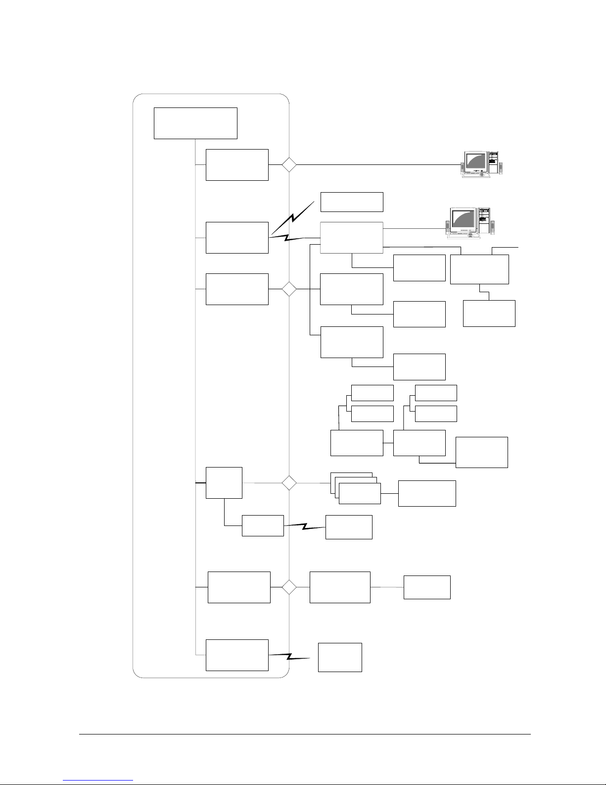
1.2.1 Options And Interfaces
USB
(Ver1.1 Function)
PC
IrDA port
(IrDA 1.0)
Bridge Satellite Cradle
DT-160IOE
Power supply
(Built-in charger)
Car mounted battery
charger
DT-167CHGE
Dual battery
charger
DT5022CHG
PC
USB
RS-232C
USB
カードDoPA
カードGPRS
Battery pack
DT-5023BAT
Large-capacity
battery pack
DT-5025LBAT
Memory card
WAN card,
etc.
Memory card,
RF card, etc.
Access-Point
Label printer, etc.
PCMCIA
Bluetooth module
(Ver1.1 Class2)
Label printer,
etc.
Communication card
cover
DT-892TCV
DT-893LTCV
DT-X10
CF card extension unit
DT-894CFU
AC adaptor
AD-S42120AE
Car Power cable
DT-827CAC
Cradle-type battery
charger
DT-169CHGE
AC adaptor
AD-S42120AE
Dual battery
charger
DT5022CHG
AC adaptor
MPC-577ADP
Battery pack
DT-5023BAT
Large-capacity
battery pack
DT-5025LBAT
Bridge Satellite
Cradle
DT-160IOE
RS-422
RS-422
AC adaptor
AD-S42120AE
Non-
Wireless
LAN model
Wirelss LAN
model
Wireless LAN
CF expansion I/F
Fig. 1.1
Page 10
10
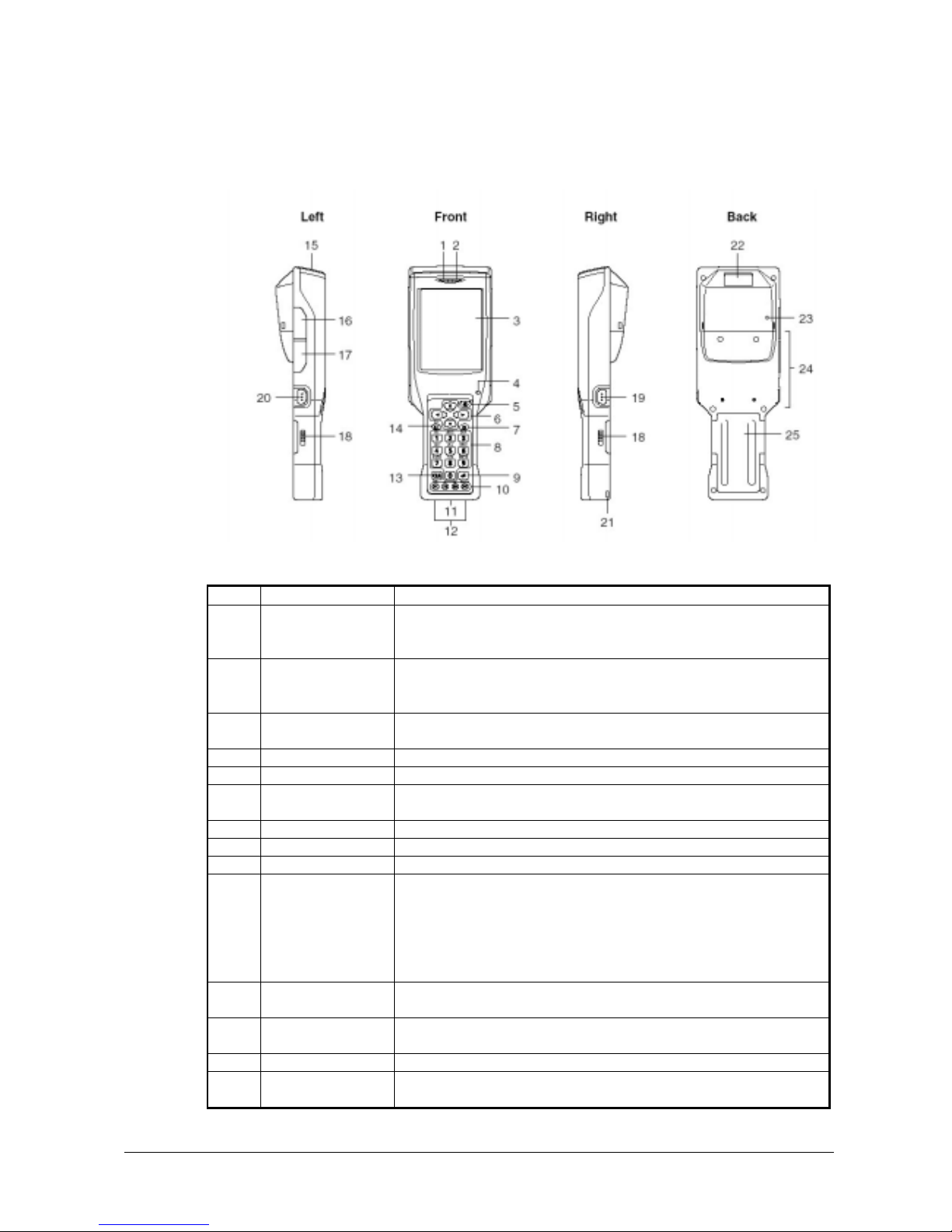
1.3 General Guide
Views
Table 1.4 Names of parts
No. Name Description
Indicates the result of a bar code read operation.
Red : Read error
1 Indicator 1
Green : Read successfully
Indicates the charge status of the battery pack.
Red : Charging
2 Indicator 2
Green : Charging complete
3 LCD panel and touch
screen
Shows text, operation indicators, etc. Also, operations can be performed and
text can be input using the supplied stylus.
4 Buzzer Sounds a buzzer.
5 Power key Hold down for about one second to turn the power on or off.
6 Cursor keys These keys operate much like a computer’s cursor keys. They can be used to
select items, scroll screen contents, etc.
7 Programmable key This key can be assigned with any function available.
8 Numeric keys Use these keys to input numbers and letters.
9 Execute key Press to register an input value and advance to the next step.
These keys can be assigned any function other than bar code reading. The
following are initial default settings.
F1 : Deletes one character to the left.
F2 : Inputs a hyphen (-).
F3 : Inputs a period (.).
10 Function keys
F4 : Toggles to switch between numbers and alphabets.
11 IR port This port is used for IR data communication with another Handheld Terminal
or the Bridge Satellite Cradle.
12 Power contacts Contact points for supplying power from the Bridge Satellite Cradle and
Cradle-type Battery Charger.
13 CLR key Press to clear all key inputs.
14 Fn key Press this key and then a function key or number key to configure settings or
to run previously registered applications.
Continue.
Fig. 1.2
Page 11

11
15 PC card slot For insertion of a separately available PC card.
16 USB port For connection to a computer or other device using a USB cable.
17 Header jack
For connection of a commercially available headset (
φ2.5mm)
18 Battery pack cover
lock switches
Slide these switches to lock and release the battery pack cover.
19 R Trigger key Press to perform a bar code read operation. This is also pressed to cancel a full
reset.
20 L Trigger key Press to perform a bar code read operation. This is also pressed to cancel a full
reset.
21 Wrist strap hole Connect the wrist strap here.
22 Reader port Emits a laser that reads bar codes.
23 Reset switch Press to reset the handheld terminal.
24 CF card slot unit
terminal
For connection of a separately available CF card Extension Unit.
25 Battery pack cover Covers the compartment that holds the battery pack.
Page 12
12
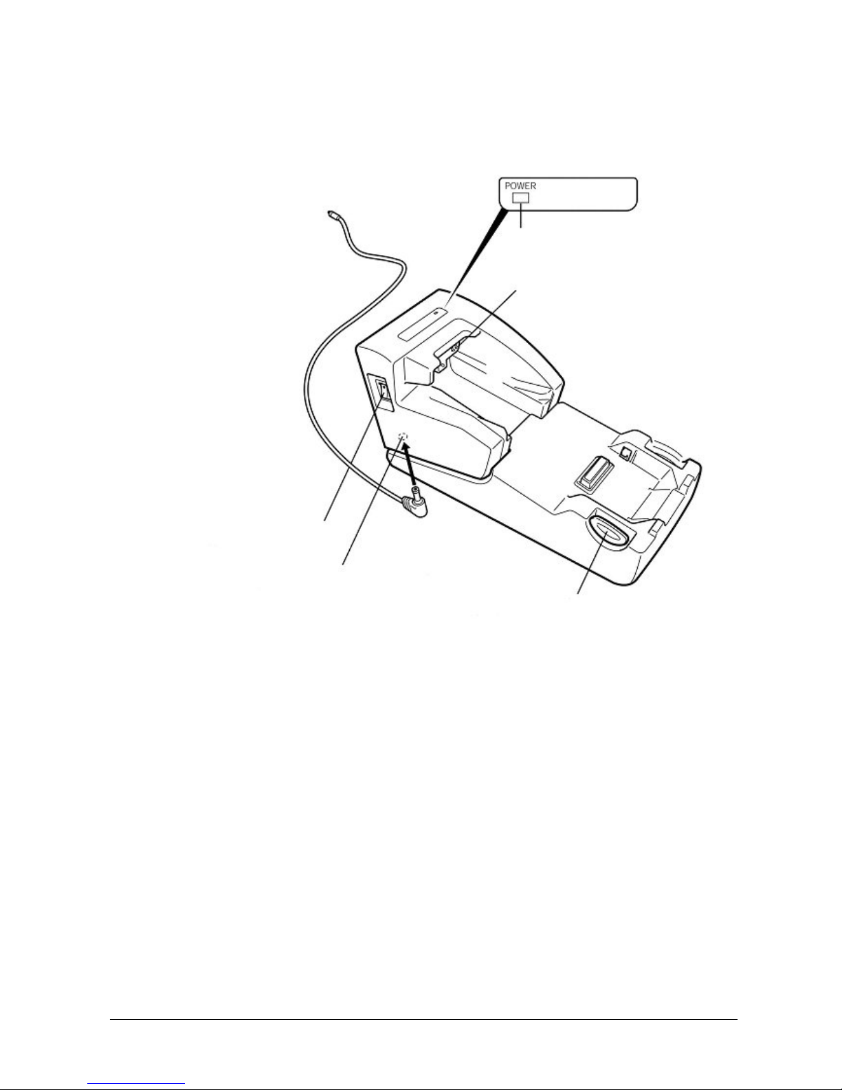
1.3.1 DT-167CHGE (Car Mounted Battery Charger)
View
Fig. 1.3
Power Indicator Lamp
Power Contacts
Power Switch
Car plug code jack
Remove button
Page 13
13
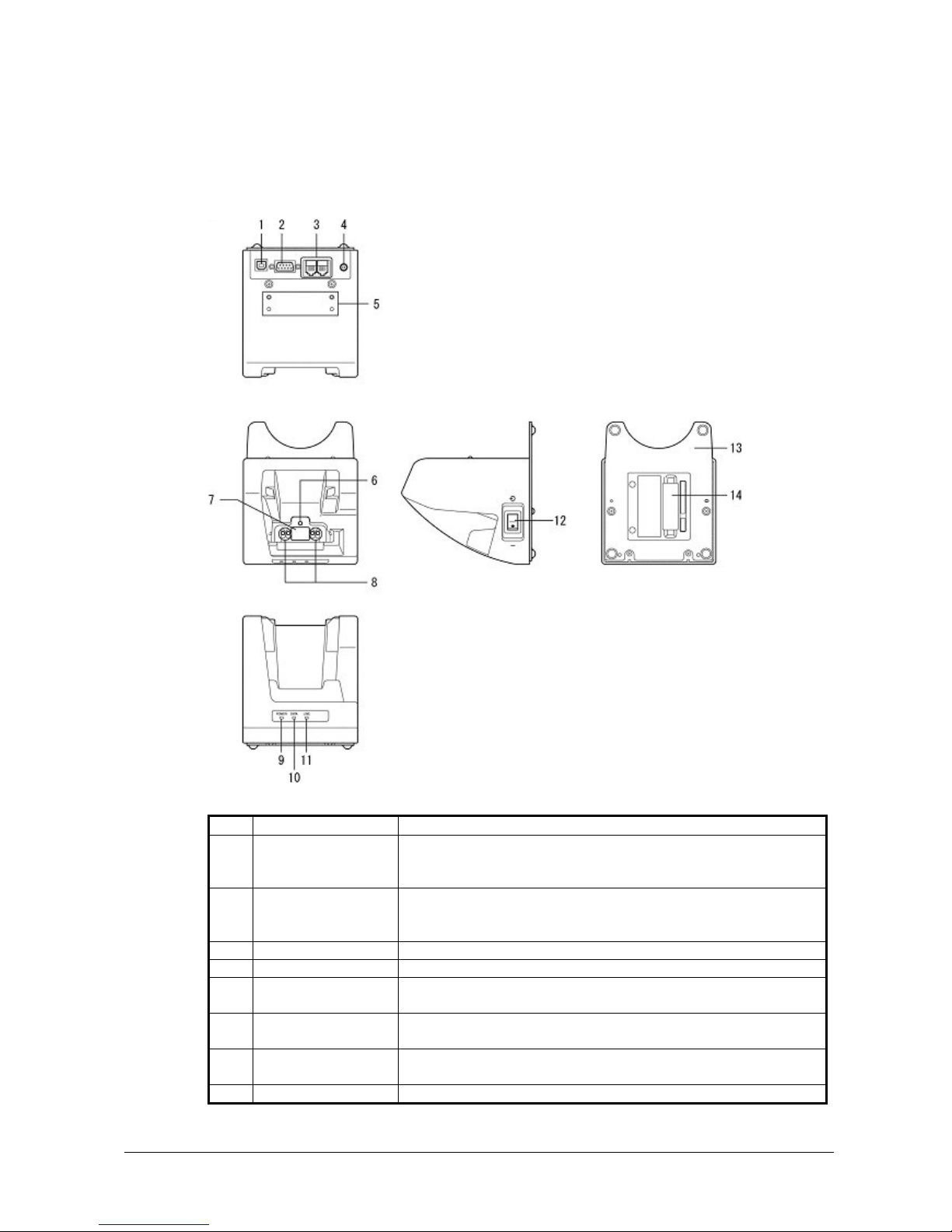
1.3.2 DT-160IOE (Bridge Satellite Cradle)
Views
Table 1.5 Names of parts
No. Part Name Description
1 USB port This port accepts connection of a USB cable for connection to a computer
for transfer of system data and file data. Use of the USB port requires
installation of a special driver on the PC.
2 RS-232C port This port accepts connection of an RS-232C cable for connection to a
computer for transfer of system data and file data. Use of the RS-232C port
requires installation of a special driver on the PC.
3 RS-422 port This port is used when connecting to another Bridge Satellite Cradle.
4 AC adaptor jack Connect the AC adaptor here.
5 Wall mount unit
fastening plate
The holes in this plate accept screws that secure the wall mount unit in place.
6 Terminal detect switch This switch detects when the Handheld Terminal is not seated correctly on
the Bridge Satellite Cradle.
7 IR port This port transfers data with the Handheld Terminal IR port non-contact data
communication.
8 Power supply terminals Power is supplied to the Handheld terminal via these contacts.
Continue.
Fig. 1.4
Back
To p
Front
Right
Bottom
Page 14

14
This lamp indicates the mounting status of the Handheld Terminal.
Off : Power off
Green : Power on, Handheld Terminal mounted correctly
9 Power indicator lamp
Red : Power on, Handheld Terminal not mounted
This lamp shows when the Handheld terminal is performing data
communication.
Off : No data communication being performed
Green flashing : Data communication in progress
10 Communication
indicator lamp
Red : Problem with a connection between two Bridge Satellite
Cradles
This lamp indicates whether the system is operating normally. Regardless of
whether or not a Handheld Terminal is mounted this lamp indicates the system
status and whether or not a communication operation with the system can be
performed.
Off : System is not operating.
11 System status
indicator lamp
Green : System is operating.
12 Power switch Turns the power on and off.
13 Desktop unit This is the base when using the Bridge Satellite Cradle in a desktop
configuration. Remove the desktop unit in the case of a wall-mount
configuration.
14 DIP switches Use these switches to configure the Bridge Satellite Cradle as required.
Page 15

15
1.3.3 DT-5022CHG (Rapid Battery Charger)
Fig. 1.5
Top
Left
Right
Bottom
Views
Charge status
indicators
Dual charger connection terminals
AC adaptor jack
Connection attachments
Battery pack compartments
Page 16

16
1.3.4 DT-5023BAT/DT-5025LBAT (Battery Packs)
Views
Fig. 1.6
DT-5023BAT DT-5025LBAT
Bottom
Bottom
Side
Sid
e
Left
Left
To p
To
p
Charge/Power supply
terminals
Charge/Power
supply terminals
Page 17

17
2. Hardware Specifications
2.1 DT-X10
Table 2.1
Item Specification Remark
CPU, Memory
CPU Intel PXA255 Application Processor Operating clock; 300 MHz (Max.)
Operating system Microsoft WindowsCE .NET 4.1
RAM 32 MB
FROM 64 MB (user area 30 MB)
Scanner
Method Semi-conductor laser light
Laser emitting window Direct
Laser light wave length 650±10 nm
Output of the light < 1 mW
No. of scannings 100±20 times per second
Resolution 0.127 mm (Minimum)
PCS 0.45 or greater Print Contrast Signal
Depth 40 to 300 mm
Maximum 30 mm (at the depth 40 mm) Readable width
Maximum 238 mm (at the depth 300 mm)
External disturbed light 50,000 Lux or less under the sunlight
Readable symbologies UPC-A, UPC-E, EAN, NW7, Code39,
Code93, Code128, EAN128,
Interleaved2of5, MSI, IATA. ITF
Display
Display device 3.5-inch 2-way TFT color LCD
No. of dots 240 (w) x 320 (h)
Dot pitch 0.22 (w) x 0.22 (h) mm
Backlight LED
Display font type Scalable fonts See note 1
Indicator
Confirmation /Status LED (in red/green) x 2 pcs Left: Programmable
Right: Battery charge status
Input
Keyboard See Chapter 1.3 “General Guide”.
Trigger key 2 keys ( left and right sides)
Touch panel Plastic panel (Resolution 240 x 320)
Possible to display character input pad
IrDA interface
Standard IrDA Ver. 1.1 compatible
Communication method Half duplex
Synchronization Start/Stop bit
Baud rate (bps) 9,600, 115,200, 4M
Communication range 0 to 1 m (Maximum 25 cm at 4 Mbps)
Bluetooth
Standard Bluetooth® Specification Ver. 1.1
Communication range 3 m Depending on the surrounding
conditions
Output Maximum 3 dBm (PowerClass2)
Continue.
Page 18

18
Serial interface
Standard USB slave Connector: USB mini-B 5-pin
Transmission speed 12 Mbps (Max.)
Audio
Earphone output, Microphone
input
φ2.5
PC card (applicable to DT-X10M10E)
Specification PC card Type I/II (3.3V/5.0V)
Supply current 450 mA (5.0V), 500 mA (3.3V) Constant supply current values
Wireless LAN interface (applicable to DT-X10M10RC and DT-X10M10RC2)
Frequency category ISM
Standard IEEE802.11b See note 2
Modulation Direct Sequence (“DS”)
Frequency band 2,400 MHz to 2,483.5 MHz
Transmission speed 11 Mbps (Maximum)
Communication range Indoor 50 m, Outdoor 150 m The range may vary depending on the
environment.
No. of channels 13 (ETSI) 3 channels for concurrent use.
Other features Roaming within multiple
Access-Points
CF card interface
Card type CF card Types I/II (3.3V)
Supply current 500 mA (3.3V) maximum
CF extension slot (Option)
Power
Operating power Lithium-ion battery pack x 1pc DT-5023BAT or DT-5025LBAT
Memory backup power Lithium secondary batter x 1pc Built-in, not replaceable 50mAH
Approx. 8 H (DT-5023BAT)
Approx. 18 H (DT-5025LBAT)
Assuming; wait:calculation:scanning 20:1:1
Approx. 4 H (DT-5023BAT)
Battery life
Approx. 10 H (DT-5025LBAT)
Assuming; wait : scanning : wireless LAN
operation 13:3:4
DT-5025LBAT 2 weeks Memory backup by
Lithium-ion battery
pack
DT-5023BAT 1 week
See note 3.
10 minutes for data in RAM Memory backup by
only Lithium secondary
battery
2 weeks for built-in clock
Under conditions with room temperature and
memory backup battery fully charged
See note 4.
Memory backup
battery charge time
4 days A period required to charge the memory backup
battery with DT-5023BAT (or DT-5025LBAT)
being installed in the terminal.
Power consumption DC2.5A/ DC3.7 to 5.0V
Buzzer
Sound pressure 70 dB or greater
Weight
Approx. 360 g DT-X10M10E
Approx. 410 g DT-X10M10RC/M10RC2
Dimensions
Approx. 220(D) x 77(W) x 47 (H) mm
Notes:
1. A font that can be used to print characters of any size.
2. Concurrent use of Wireless LAN communication with Bluetooth communication is not recommended.
3. Each memory backup period will depend on the characteristic of terminal itself, the surroundings including
temperature, humidity. Thus, the periods described in Table 4.1 are recommended for use for reference
only. They are not guaranteed figures.
4. Backup for both data in RAM and the RTC (built-in clock) will commence when the battery pack (either
DT-5023BAT or DT-5025LBAT) runs down.
Page 19

19
2.2 DT-160IOE (Bridge Satellite Cradle)
Table 2.2
Item Specification Remark
Standard IrDA Ver. 1.1 compatible
Comm. method Half duplex
Synchronization Start/stop method
IrDA
Comm. speed 4 Mbps (maximum)
Standard USB Ver. 1.1 compatible
Comm. speed 12 Mbps (maximum)
USB
Connector
USB connector type B
1. VBus
2. –Data (D-)
3. +Data (D+)
4. GND
Comm. method Full duplex
Synchronization Start/stop method
Comm. speed 115.2 Kbps
RS-232C
Connector
D-Sub 9-pin (Male)
Comm. method Full duplex
Synchronization Start/stop method
Comm. speed 115.2 Kbps
Interface
RS-422
Connector
RJ-45 compatible (6 pins)
No. of LEDs 3
No. of display colors 2 Red, green
Display Status LED
Display content
System operation status (“LINE”)
Comm. status (“DATA”)
Power status (“POWER”)
Refer to Chapter 2.6
“Status Indication
With LEDs”.
DIP switch 8 switches See page 22.
Input
Detection switch for DT-X10 Push switch
Input voltage
DC 12V±5%
Consumption current
Approx. 1,600 mA While supplying
power or transmitting
data.
Plug EIAJ RC-5320A Class 4 Center: plus
Input from AC
adaptor
AC adaptor AD-S42120AE
Output voltage
DC 5V±10%
Output current 2,500 mA (maximum)
Charge method Constant voltage With curb function on
current
Approx. 2.5 hours For DT-5023BAT
Power
Charge/supply
power
Charge time
Approx. 5.0 hours For DT-5025LBAT
Continue.
2
4
1
2
SG ER SD RD CD
CI CS RS D
RDI-
RDI+
SDO-
SDO+
RSO-
RSO+
OU
T
IN
RD0-
RDO+
SDI-
SDI+
RSI-
RSI+
Page 20

20
Power supply terminals
The illustration of
the power supply
terminals on the left
is viewed at the
front of the cradle.
Weight/Dimensions
Table 2.3
Specification Remark
In desktop state Approx. 490 g
Weight
In wall mount state Approx. 650 g
In desktop state Approx. 110 (W) x 139 (D) x 129 (H) mm
Dimensions
In wall mount state Approx. 110 (W) x 148 (D) x 153 (H) mm
2.3 DT-167CHGE (Car Mounted Battery Charger)
Table 2.4
Item Specification Remark
No. of LEDs 1
No. of display colors 2 In red and green
Display content Power status (“POWER”)
Indicates the status of terminal being mounted on the charger.
OFF : Power is OFF.
Flashing in green : Power is ON and the terminal is mounted on the charger.
Display Status LED
Flashing in red : Power is ON but the terminal is not mounted on the charger.
Input Detection switch for DT-X10 Push switch
Input voltage
DC 12V/24V±5%
DC 12V : Approx. 1,400 mA
Consumption current
DC 24V : Approx. 700 mA
While supplying
power.
Plug EIAJ RC-5320A Class 4 Center: plus
Input from
power adaptor
Power cord DT-827CAC
Output voltage
DC 5V±10%
Output current 2,500 mA (maximum)
Charge method Constant voltage With curb function
on current
Approx. 2.5 hours For DT-5023BAT
Charge time
Approx. 5.0 hours For DT-5025LBAT
Power
Charge/supply
power
Power supply terminals
The illustration of
the power supply
terminals on the left
is viewed at the
front of the charger.
Weight/Dimensions
Table 2.5
Specification Remark
Weight Approx. 755 g
Dimensions Approx. 119 (W) x 267 (D) x 123 (H) mm
GND
Power supply
terminals
GND
Power supply
terminals
Page 21

21
2.4 DT-169CHGE (Cradle-type Battery Charger)
Table 2.6
Item Specification Remark
No. of LEDs 1
No. of display colors 2 In red and green
Display Status LED
Display content Power status (“POWER”)
Input Detection switch for DT-X10 Push switch
Input voltage
DC 12V±5%
Consumption current Approx. 1,400 mA While supplying
power or
transmitting data.
Plug EIAJ RC-5320A Class 4 Center: plus
Input from AC
adaptor
AC adaptor AD-S42120AE
Output voltage
DC5V±10%
Output current 2,500 mA (maximum)
Charge method Constant voltage With current curb
function
Approx. 2.5 hours For DT-5023BAT
Charge time
Approx. 5.0 hours For DT-5025LBAT
Power
Charge/Power
supply
Power supply terminal
The illustration of
the power supply
terminals on the left
is viewed at the front
of the charger.
Weight/Dimensions
Table 2.7
Specification Remark
In desktop state Approx. 470 g
Weight
In wall mount state Approx. 630 g
In desktop state Approx. 110 (W) x 139 (D) x 129 (H) mm
Dimensions
In wall mount state Approx. 110 (W) x 148 (D) x 153 (H) mm
GND
Power supply
terminals
Page 22

22
2.5 DIP Switch Setting (For DT-160IOE)
The DIP switch is located on the rear side of the Bridge Satellite Cradle. Change the ON/OFF settings according
to your required system configuration. The new settings do not go into effect until the power switch is turned off
and then back on again.
ON Upper side)
OF
F
(Lower side)
Not used (Always set to "OFF")
Not used (Always set to "OFF")
Host computer interface
Interface 6
RS-232C OFF
USB * ON
Termination setting for daisy chain connection
Termination 5
At middle OFF
No chain/Termination* ON
Connection mode
Mode 3 4
With Host PC* OFF OFF
Chain connection ON OFF
Communication speed between Cradles
Baud rate 1 2
115,200bps * ON OFF
Note:
Other DIP switch settings are used for testing and inspection purposes Because of this, you must not use any
DIP settings other than those described above.
Fig. 2.1
Page 23

23
2.6 Status Indication With LEDs
Various operational statuses on the DT-160IOE can be displayed using the LEDs. The following table describes
LED modes and their meanings.
Table 2.8
Item Specification Remark
LED
DT-X10 is not mounted LED ON in red
DT-X10 is mounted LED ON in green
Power status indicator
(POWER)
Power OFF LED OFF
2-color LED
Break of communication LED OFF
Communication is in progress LED flash in green
Comm. status indicator
(DATA)
Connection between cradle and PC is not
valid.
LED ON in red
2-color LED
No comm. with DT-X10 or abnormality
of the system
LED OFF
Line status indicator
(LINE)
Communication is in progress with
DT-X10.
LED ON in green
2-color LED
2.7 DT-5022CHG (Rapid Battery Charger)
Basic Block
Table 2.9
Item Specification Remark
Basic function
Rechargeable battery pack
DT-5023BAT Standard size battery pack
DT-5025LBAT Large-capacity size battery pack
Dedicated batteries only.
AC adaptor
MPC-577ADP AC100V to 240V input
Interface Block
Table 2.10
Item Specification Remark
Input terminals for joint block
1: VIN2 Rated DC16V Input voltage 8 to 20V
2: VIN3 Rated DC16V Input voltage 8 to 20V
3: NC NC
4: GND GND
Output terminals for joint block
1: VOUT1 DC16V Output terminal from 1st unit when AC
adaptor is used.
2: VOUT2 DC16V Output terminal from 2nd unit
3: NC NC
4: GND GND
No. of joint-able units 3 units (DT-5022CHG x 3pcs)
Page 24

24
Power Supply Block
Table 2.11
Item Specification Remark
Input
Rated voltage DC16V
Input voltage DC8.0 to 20V
Rated output
Rated output voltage DC4.22V
Rated output current DC1,600 mA
Input consumption current
Input consumption current 0.65 A When input voltage is at 16V.
Charge output terminal CH1
PIN1: + 4.22V±30mV
PIN2: - GND
Charge output terminal CH2
PIN1: + 4.22V±30mV
PIN2: - GND
Input terminal
DC jack Rated DC16V, input voltage DC 8.0 to 20.0V
Battery Charge Block
Table 2.12
Item Specification Remark
Charge control
Output voltage DC4.22V±30mV
Charge current (standard mode) DC1,600mA±10%
Charge current (standby mode) DC160±40mA
Full charge detection current DC120±30mA
Full charge detection voltage 4.1V Voltage control
Re-charge detection voltage 4.0V
Re-charge detection voltage DC4.0±0.1V
Input voltage DC8.0 to 20V
Timer
Charge timer (standby mode) 90 minutes
Charge timer (standard mode) 720 minutes
Trickle charge timer 120 minutes
Charge hour
DT-5023BAT Approx. 2.5 hours (for 1 pack)
Approx. 5 hours (for 2 packs at same time)
At 0 to 40 ºC
DT-5025LBAT Approx. 5 hours (for 1 pack)
Approx. 10 hours (for 2 packs at same time)
At 0 to 40 ºC
Temperature control Not available
No. of charge output 1
Operation mode
Battery pack mount detection
Battery pack not mounted LED OFF, charge output OFF
Battery pack mounted LED ON in red, charge output OFF
Check on battery pack LED ON in red, charge output OFF
Battery charge (standby mode) LED ON in red, charge output ON
Battery charge (standard mode) LED ON in red, charge output ON
Wait mode in trickle charge LED ON in green, charge output OFF
Charge in trickle mode LED ON in green, charge output ON
Charge completed LED ON in green, charge output OFF
Charge abnormal end LED flash in red, charge output OFF
Other
Priority order of battery charging Order in mounted order
Page 25

25
Weight/Dimensions
Table 2.13
Item Specification Remark
Weight Approx. 154 g
Dimensions 100 (L) x 110 (W) x 49 (H) mm
2.8 DT-5023BAT/DT-5025LBAT
Table 2.14
Specification Item
DT-5023BAT DT-5025LBAT
Remark
Rated capacity 1,550 mAh 3,400 mAh 0.2C discharge
Rated voltage 3.7V 3.7V 0.2C discharge
Discharge end voltage 2.75V 2.75V
Standard charge current 1.0 CA (=1.55A)
0 to 40 ºC
1.6A
0 to 50 ºC
Charge voltage 4.2±0.05V 4.2±0.05V
Charge hour
(standard mode)
2.5 hours 5.0 hours Charge with
DT-5022CHG
Weight 50 g or less 100 g or less
Dimensions 57 (L) x 37 (W) x 12.8 (H) mm 57 (L) x 37 (W) x 24 (H) mm
2.9 DT-894CFU (CF Card Extension Unit)
Dimensions/Weight
Table 2.15
Specification Remark
Approx. 70 (W) x 87 (D) x 13 (D) mm With standard size cover
Dimensions
Approx. 85 (W) x 78 (D) x 13 (D) mm With large size cover
Approx. 40 g With standard size cover
Weight
Approx. 45 g With large size cover
Note:
Standard size cover and large size cover come as standard.
Fig. 2.2
Page 26

26
3. Interfaces
3.1 DT-X10
CF Extension Slot
Table 3.1 CF extension slot
Specification Remark
Interface CFA Rev.1.3 compatible CF Type I/II 3.3V only
Power voltage 3.3V ±5%
Supply current 300 mA (maximum)
Pin Assignment
Table 3.2
Memory Mode I/O Mode Memory Mode I/O Mode
Name I/O Name I/O
Pin no. Pin no.
Name I/O Name I/O
GND P GND P 1 26 -CD1 I -CD1 I
D03 I/O D03 I/O 2 27 D11 I/O D11 I/O
D04 I/O D04 I/O 3 28 D12 I/O D12 I/O
D05 I/O D05 I/O 4 29 D13 I/O D13 I/O
D06 I/O D06 I/O 5 30 D14 I/O D14 I/O
D07 I/O D07 I/O 6 31 D15 I/O D15 I/O
-CE1 O -CE1 O 7 32 -CE2 O -CE2 O
A10 O A10 O 8 33 -VS1 I -VS1 I
-OE O -OE O 9 34 -IORD O -IORD O
A09 O A09 O 10 35 -IOWR O -IOWR O
A08 O A08 O 11 36 -WE O -WE O
A07 O A07 O 12 37 RDY/BSY I IOREQ I
VCC P VCC P 13 38 VCC P VCC P
A06 O A06 O 14 39 -CSEL O -CSEL O
A05 O A05 O 15 40 -VS2 I -VS2 I
A04 O A04 O 16 41 RESET O RESET O
A03 O A03 O 17 42 -WAIT I -WAIT I
A02 O A02 O 18 43 -INPACK I -INPACK I
A01 O A01 O 19 44 -REG O -REG O
A00 O A00 O 20 45 BVD2 I/O -SPKR I/O
D00 I/O D00 I/O 21 46 BVD1 I/O -STSCHG I/O
D01 I/O D01 I/O 22 47 D08 I/O D08 I/O
D02 I/O D02 I/O 23 48 D09 I/O D09 I/O
WP - -IOIS16 - 24 49 D10 I/O D10 I/O
-CD2 I -CD2 I 25 50 GND P GND P
Direction of data flow; I; DT-X10←CF card, O; DT-X10→CF card, I/O; DT-X10 ⇔CF card, P; power,
GND
Page 27

27
Table 3.3 IrDA interface
Item Specification Remark
Comm. speed, modulation
Standard IrDA Ver. 1.1 compatible
FIR 4 Mbps 4-value PPM modulation
MIR 1.152 M, 576 Kbps NRZ modulation
SIR 2.4 K to 115.2 Kbps NRZ modulation
Emission unit
Peak wave length 880 to 900 nm
Emission strength Type 75 mW/sr
Emission angle
±15°
Reception unit
Reception wave length 850 to 900 nm
SIR: 0.75 mW/cm2 or less
Incident illuminant
FIR: 200 to 0.75, 0.33 to 0.12 mW/cm
2
Comm. range 0 to 1m (Maximum 25 cm at 4 Mbps)
Connectable devices
HT-to-HT comm. Between DT-X10 and DT-X10
Comm. via cradle Bridge Satellite Cradle (DT-160IOE)
Table3.4 Earphone
Item Specification Remark
Method Monaural
Connectable device Earphone
Table 3.5 Power supply
Item Specification Remark/Condition
DT-5023BAT/DT-5025LBAT
Rated voltage 3.7 V
Rated capacity 1,550 mAh (DT-5023BAT)
3,400 mAh (DT-5025LBAT)
Approx. 8 hours (DT-5023BAT)
Approx. 18 hours (DT-5025LBAT)
• In case of Wait : Calculation :
Scanning 20:1:1
Approx. 4 hours (DT-5023BAT)
Operating hours
Approx. 10 hours (DT-5025LBAT)
• For DT-X10M10RC/M10RC2
• In case of Wait : Scanning : Wireless
LAN operation 13:3:4
10 minutes for data in RAM
Data backup hours
2 weeks for built-in Real Time Clock
• At moderate temperature
• Sub-battery is fully charged.
Recharge
sub-battery
4 days
• Period required for the sub-battery
being charged fully when the battery
pack is installed
Sub-battery
Battery type Button-shape Lithium rechargeable battery
(CR-2032)
Rated voltage 3.0 V
Battery low warning
Low main battery voltage VDET1: 3.4 V Warning display, but still operable
Forcible OFF VDET2: 3.0 V Forcible OFF
Low sub-battery voltage VDETS: 2.3 V Data cannot be retained.
Page 28

28
4. Product Identification And Reference Numbers
On the back of the terminal and its options (major options only), there is a bar code and numbers printed on label
as shown in Fig. 4.1 below.
This bar code is represented by 15 digits of CODE128 and by alphanumeric characters beneath the bar code.
The numbers from 1 to 9 in the figure represent identification and references of the terminal. The numbers from
10 to 14 represent a manufacturing reference which is reserved by the manufacturer. See the figure below for
each meaning.
1234 56789101112131415
Production month of the year (1 to 9, A,B,C)
Production year (last digit only. Ex. 1 represents the year 2001.)
Model number (two digits in alphanumeric)
29: DT-X10 (Domestic version)
32: DT-X10 (Domestic version)
35: DT-X10 (Domestic version)
38: DT-X10 (Domestic version)
68: DT-X10M10E
70: DT-X10M10RC
6B: DT-X10M10RC2
41: DT-861IO (Domestic version)
42: DT-160IOE
43: DT-868CHG
44: DT-169CHGE
62: DT-867CHG (Domestic version)
63: DT-167CHGE
Serial number of the
terminal in 5 digits
Manufacturing references
(reserved by the
manufacturer)
Check digit
Fig.4.1
Page 29

29
5. Quality References
This chapter will describe about references of the DT-X10 and its dedicated options concerned with
environmental performance, compliance, mechanical and electric durability, etc.
5.1 Environmental Performances
5.1.1 DT-X10
Table 5.1
Item Specification Condition
Operation -10 to 50 ºC
Temperature
Non-operation -20 to 60 ºC
Operation 10 % to 80 %RH No condensation
Humidity
Non-operation 5% to 90 %RH No condensation
Storage in carton box
Temperature -10 to 50 ºC
Humidity 90 %RH or less No condensation
Dust and water-splash proof
IP54 level (compliant with IEC5291) All covers on the terminal
are closed.
5.1.2 DT-160IOE/DT-169CHGE
Table 5.2
Item Specification Condition
Operation 0 to 40 ºC
Temperature
Storage -10 to 50 ºC
Operation 30 to 80%RH No condensation
Humidity
Storage 30 to 90%RH No condensation
Temperature -10 to 50 ºC
Storage in
carton box
Humidity 30 to 90%RH No condensation
Page 30

30
5.1.3 DT-167CHGE
Table 5.3
Item Specification Condition
Operation 0 to 40 ºC
Temperature
Storage -40 to 85 ºC
Operation 30 to 80%RH No condensation
Humidity
Storage 30 to 95%RH No condensation
Temperature -10 to 50 ºC
Storage in
carton box
Humidity 30 to 90%RH No condensation
5.1.4 DT-5022CHG
Table 5.4
Item Specification Condition
Operation 0 to 40 ºC
Non-operation -10 to 50 ºC When battery is not charged.
Temperature
Storage -10 to 55 ºC
Operation 20 to 90 %RH No condensation
Humidity
Storage 20 to 90 %RH No condensation
Storage in carton box
Temperature -10 to 55 ºC
Humidity 20 to 90 %RH No condensation
5.1.5 DT-5023BAT/DT-5025LBAT
Table 5.5
Item Specification Condition
Operation 0 to 40 ºC
Non-operation -5 to 50 ºC When battery is not charged.
Temperature
Storage -10 to 55 ºC
Operation 20 % to 90 %RH No condensation
Humidity
Storage 20 % to 90 %RH No condensation
Storage in carton box
Temperature -10 to 55 ºC
Humidity 90 %RH or less No condensation
Page 31

31
5.1.6 DT-894CFU
Table 5.6
Item Specification Condition
Operation -20 to 50 ºC
Temperature
Non-operation -20 to 70 ºC
Operation 10 to 80 %RH No condensation
Humidity
Storage 5 to 90 %RH No condensation
Storage in carton box
Temperature -10 to 50 ºC
Humidity 90 %RH or less No condensation
Dust and water-splash proof
IP64 level (compliant with IEC5291) All connectors are covered.
Page 32

32
5.2 Electrical Performances
5.2.1 DT-X10
Table 5.7
Item Specification Remark
Power consumption DC 2.5A/3.7 to 5.0V
Anti-static strength
Malfunction
±6 KV
Destruction
±12 KV
150 pF, 330 ohm
5.2.2 DT-160IOE/DT-169CHGE
Table 5.8
Item Specification Remark
Approx. 0.1 A When DT-X10 is not mounted on. Current
consumption
Approx. 1.6 A While supplying power or transmitting data.
Vo l t a g e
DC12V
±5%
Anti-static strength
Malfunction
±6 KV
Destruction
±12 KV
150 pF, 330 ohm
Line noise strength
(Malfunction)
1,000 V Pulse width: 5 KHz
Burst cycle: 300 msec.
No. of pulses: 75 pcs
Burst period: 15 msec.
Power interruption 10 milliseconds or less
5.2.3 DT-167CHGE
Table 5.9
Item Specification Remark
DC 12V : Approx. 1,400 mA Consumption
current
DC 24V : Approx. 700 mA
While supplying power.
Vo l t a g e
DC 12V/24V±5%
Anti-static strength
Malfunction
±6 KV
Destruction
±12 KV
150 pF, 330 ohm
Page 33

33
5.2.4 DT-5022CHG
Table 5.10
Item Specification Remark
Anti-static strength
Malfunction ±5 KV
Destruction ±10 KV
ESD method: 250 pF, 100 ohm
Probe: Finger type
Polarity: ±
5.2.5 DT-5023BAT/DT-5025LBAT
Table 5.11
Item Specification Remark
Anti-static strength
Malfunction ±5 KV
Destruction ±10 KV
ESD method: 250 pF, 100 ohm
Probe: Finger type
Polarity: ±
5.2.6 DT-894CFU (CF Card Extension Unit)
Table 5.12
Item Specification Remark
Power consumption DC 0.65A / 3.0 to 5.0V
Anti-static strength
Malfunction ±6 KV
Destruction ±12 KV
150 pF, 330 ohm
Page 34

34
5.3 Mechanical Performances
5.3.1 DT-X10
Table 5.13
Item Specification Condition
Resistance to drop impact (height)
In bare condition 120 cm Onto concrete, three times on each of the 6 sides and
4 corners.
In individual carton
box
70 cm or less
In master carton box 50 cm or less
Onto concrete, one time on each of the 6 sides, 1
corner, 3 edges.
Resistance to vibration 0.15 G or less 10 to 55 Hz
In X,Y, and Z directions
Reciprocally for 30 minutes
Resistance to vibration
(in package)
1.5 G or less 10 to 55 Hz
In X,Y, and Z directions
Reciprocally for 30 minutes
5.3.2 DT-160IOE/DT-169CHGE
Table 5.14
Item Specification Condition
Resistance to vibration 0.15 G or less 10 to 55 Hz
In X,Y, and Z directions
Reciprocally for 30 minutes
Resistance to vibration
(in package)
1.5 G or less 10 to 55 Hz
In X,Y, and Z directions
Reciprocally for 30 minutes
Resistance to impact
In bare condition 70 cm One time for 6 faces onto concrete surface
In individual carton box 70 cm or less
In master carton box 50 cm or less
One time for 6 faces, 1 corner and 3 edges
5.3.3 DT-5022CHG
Table 5.15
Item Specification Condition
Resistance to vibration 1 G or less 10 to 55 Hz
In X,Y, and Z directions
Reciprocally for 30 minutes
Resistance to vibration
(in package)
2 G or less 10 to 55 Hz
In X,Y, and Z directions
Reciprocally for 15 minutes
Resistance to impact
In bare condition 75 cm 6 faces, 1 corner and 3 edges
In individual carton box 75 cm or less 6 faces, 1 corner and 3 edges
Page 35

35
5.3.4 DT-5023BAT/DT-5025LBAT
Table 5.16
Item Specification Condition
Resistance to vibration 1 G 10 to 55 Hz
In X,Y, and Z directions
Reciprocally for 30 minutes
Resistance to vibration
(in carton box)
2 G 10 to 55 Hz
In X,Y, and Z directions
Reciprocally for 30 minutes
Resistance to impact
In bare condition 75 cm 6 faces, 1 corner and 3 edges onto P tile.
In individual carton box 75 cm or less 6 faces, 1 corner and 3 edges onto P tile.
5.3.5 DT-894CFU (CF Card Extension Unit)
Table 5.17
Item Specification Condition
Resistance to vibration 0.15 G or less 10 to 55 Hz
In X,Y, and Z directions
Reciprocally for 30
minutes
The unit is installed on
the DT-X10.
With the extension unit
installed on the terminal
Resistance to impact
120 cm 3 times of each faces (6
faces) and corner (4
corners) onto concrete
surface
With the standard size
card cover installed on the
terminal.
In bare condition
40 cm 1 time of each faces (6
faces) and corner (4
corners) onto lauan wood
surface
With the large-sized card
cover installed on the
terminal.
In individual carton box 70 cm or less
In master carton box 50 cm or less
1 time of each face (6 faces), corner (1 ) and edge (3
edges)
Page 36

36
5.4 Reliability
5.4.1 DT-X10
Table 5.18
Item Specification Remark/Condition
Service life
Backlight 20,000 hours At half-life period
Scanner module 10,000 hours
USB connector 5,000 times
PC Card slot cover 100 times
Trigger keys 1,000,000 times Each trigger key
Other keys 500,000 times
Mounting/removing of DT-X10
to/from the Cradle
10,000 times
Key input 800,000 times Touch
panel
Writing 100,000 with Katakana
characters
With 0.8R polyester stylus with load of 250 g
applied
MTBF 64,685 hours Electronic parts only
MTBF (Wireless LAN module) 27,000 hours
Charging and discharging cycle
of battery pack
300 times or more Applicable to DT-5023BAT/DT-5025LBAT
5.4.2 DT-160IOE/DT-169CHGE
Table 5.19
Item Specification Remark/Condition
MTBF for electronics parts 50,000 hours
Mounting/removing DT-X10 to/from Cradle 20,000 times
Power switch 5,000 times
Switch
DIP switch 10 times
USB 500 times
RS-232C 500 times
No. of ON/OFF times of the
connector
RS-422 100 times
No. of ON/OFF times of the power jack 1,500 times
5.4.3 DT-5022CHG
Table 5.20
Item Specification Remark
MTBF 210,000 hours or more MIL-HDBK217F
Protection from short Internal circuit is protected from a short between
the charge terminals
Page 37

37
5.5 Compliance
5.5.1 DT-X10
EMC, EMI, Safety, Wireless LAN /Bluetooth type approvals
Table 5.21
Standard
Model
EN301.489-17
(EMI,EMS)
EN60950 EN60825
(Class 2)
EN300.328-2
DT- X 10 M 1 0E Ye s Yes Yes Yes
DT- X 10 M 1 0R C Yes Yes Ye s Yes
DT- X 10 M 1 0R C 2 Ye s Ye s Ye s Ye s
5.5.2 DT-160IOE/DT-169CHGE
Table 5.22
Standard
EN55022:1998+A1:2000 Class B EMC
EN55024:1998+A1:2001 Class B
Safety EN60950
Page 38

38
6. Cable Specifications
6.1 For Chain Connection And Short Length
Length; 1 meter or less
1 2 3 4 5 6
Maxmimum
1m
Modular plug
(comppatible with
6/6-6FR SYK (Sabyo
Industrial)
1 2 3 4 5 6
Cable(see Table 6.1)
Table 6.1 Specifications of the cable
Cable
Conductor 20/0.1A
Insulator Semi-hard material P.V.C.
Core wire
Finish of external shape 20/0.1A
Insulator P.V.C. Sheath
Finish of external shape
φ4.3±0.1mm
Conductance resistance
0.12Ω/m or less
Characteristics
Insulation resistance
50MΩ or more
Pin layout diagram of cable for chain connection and short distance (pin-to-pin straight connection)
Wiring
Pin no. Signal Pin no. Signal
1 IRS+ 1 ORS+
2 IRS- 2 ORS3 ISD+ 3 OSD+
4 ISD- 4 OSD5 ORD+ 5 IRD+
6 ORD- 6 IRD-
Cradle at lower
position under the
chain connection
Cradle at higher
position under the
chain connection
Vie w from sid e
Vie w from top
Fig. 6.1
Fig. 6.2
Page 39

39
6.2 For Chain Connection And Long Length
Length; 1 meter or longer
1 2 3 4 5 6
Max. 1,000m
Modular plug compatible
with 6/6-6 FR SYK50 by
Sanyo Industrial Co.
1 2 3 4 5 6
Cable compatible with SK-UTP
100M3P by Sanyo Industrial Co.
Pin layout diagram of cable for chain connection and long distance (pin-to-pin straight/twist-pair connection)
Wiring
Pin no. Signal Pin no. Signal
1 IRS+ 1 ORS+
2 IRS- 2 ORS3 ISD+ 3 OSD+
4 ISD- 4 OSD5 ORD+ 5 IRD+
6 ORD- 6 IRD-
Cradle at lower
position under the
chain connection
Cradle at higher
position under the
chain connection
Fig. 6.3
XXXXX
X
XXXXX
X
XXXXXX
Vie w from sid e
Vie w from top
Fig. 6.4
Page 40

40
7. Precautions
7.1 Handling Precautions
Precautions for short-term storage (1 to 2 days)
• If the DT-X10 is to be stored over a holiday period (non-working days, e.g. Saturday and Sunday), replace
the DT-5023BAT (or DT-5025LBAT) battery with fully charged DT-5023BAT before it is stored. This will
conserve the memory backup battery and ensure retention of data on the DT-X10.
• If there is a possibility of the above or operator error (e.g., a fully charged battery has not been inserted),
practice system operation that maintains a backup to avoid loss of data due to consumption of the batteries.
Precautions for long-term storage (over one week)
• Prior to long-term storage (over one week), always back-up the data. In addition, remove all the batteries
before storage. This can minimize overly discharging the DT-5023BAT battery and minimize
consumption of the memory backup battery.
• Do not store the removed batteries at high temperature. Otherwise, both the batteries will discharge at an
accelerated rate. Note that the capacity after the battery if it is not used for 10 days at 60°C will be 65%,
and that after 20 days at 60°C will be 55%.
Page 41

41
7.2 Safety
7.2.1 Battery Pack
• Never disassemble or retrofit the battery pack. The battery pack has safety mechanism and protection
means incorporated to avoid hazards. Should they be damaged, the battery pack could become hot,
generate smoke, explode, or ignite.
• Never contact the “+” and “-“ terminals with metal objects such as a wire. Also, do not carry or store the
battery with a metal necklace or hair pin. Otherwise, the battery pack may be short-circuited resulting in an
excessive current and causing the battery to become hot, smoke, explode, or catch fire.
• Neither dispose of the battery pack into a fire nor heat it. The insulation may be burnt, the gas exhaust
valve or safety mechanism may be damaged, or the internal electrolyte may ignite, causing the battery
pack to become hot, smoke, explode, or ignite.
• Neither leave nor use the battery pack in a place with a high temperature (over 80°C) or close to a fire or
hot stove. Should the resin separator be damaged due to excessive heat, the battery pack may be
short-circuited causing it to become heated, smoke, explode, or ignite.
• Do not soak the battery pack in fresh water or sea water. If the protection means incorporated in the battery
pack is damaged, the battery pack may become hot, smoke, explode, or ignite.
• Do not attempt to charge the battery close to a fire, in direct sunlight, or in a car parked in the sun. A heated
battery pack will trigger the internal hazard protection means to stop the charging function. Or, the
protection means may be damaged and the battery may be charged with an excessive current or voltage, or
have abnormal chemical reactions induced to cause it to become hot, smoke, explode, or ignite.
• Do not stick a pin or nail in the battery pack. Neither hit it with a hammer nor stamp it. If this is done, the
battery pack may be broken or deformed resulting in a short circuit and causing it to become hot, smoke,
explode, or ignite.
• Do not hit or throw the battery pack. If the protection means incorporated in the battery pack is damaged,
the battery pack may be charged with an excessive current or voltage, or have abnormal chemical
reactions induced to cause it to become hot, smoke, explode, or ignite.
• Never use a battery pack that is significantly damaged or deformed. It may become hot, smoke, explosion,
or ignite.
• Do not attempt to solder anything directly on the battery pack surface. The insulation may be damaged or
the gas exhaust valve or safety mechanism may be damaged, causing the battery pack to become hot,
smoke, explode, or ignite.
• Do not use the battery pack in other device than the DT-X10. The performance or service life of the battery
pack may be reduced or abnormal current may flow to cause it to become hot, smoke, explode, or ignite.
Page 42

42
• When charging the battery pack use only the dedicated AC adaptor supplied from CASIO, at a
temperature between 0°C and 40°C. If the battery pack is charged with chargers other than those specified
by CASIO, it may be over-charged, or charged with an excessive current, or have abnormal chemical
reactions induced, causing it to become hot, smoke, explode, or ignite.
• The battery pack has a specific polarity. Do not force it into the DT-X10. Check the polarity. If the battery
pack is connected backwards, it can be incorrectly charged and have an abnormal chemical reaction
induced, causing it to become hot, smoke, explode, or ignite.
• If the internal electrolyte of the battery pack leaks and enters the eye, do not rub the eye. Rinse the eye with
a sufficient amount of clean water, such as tap water, then immediately consult with a doctor. The
electrolyte can cause eye damage.
7.2.2 General
• Be aware of abnormal conditions.
If the DT-X10 is continuously used in an abnormal condition, a fire or electric shock may occur. If there is
an abnormality, immediately turn off the Power switch, and be sure to remove the batteries and unplug the
AC adaptor from the wall outlet, then contact a CASIO distributor for repair.
• Supply Current/Voltage
Do not use the AC adaptor with an AC voltage other than that indicated. Also, avoid drawing power from
an outlet used for multiple devices. This may cause fire or an electric shock.
• Handling the power cable
Do not damage, break, retrofit, bend, twist, or stretch the power cable. Also, do not place a heavy object on
it or heat it. If this is done, the power cable may be broken and cause a fire or electric shock.
• AC adaptor
Always use the dedicated AC adaptor. If an AC adaptor that is not specified is used, the battery pack may
explode, causing a fire or personal injury.
• Do not touch the AC adaptor with wet hands.
This may result in an electric shock. Also, place the AC adaptor in a place where it is not subject to dust
and water. Dust and dirt may cause fire and smoke, and water may cause an electric shock.
• About the electrolyte
If the internal electrolyte of the battery leaks and enters the eye, rinse it with a sufficient amount of water,
then consult with a doctor
Page 43

43
• About the battery pack
1. Do not place the battery pack in a microwave oven or high-pressure container. If this is done, the
battery pack will be quickly heated or the contact seal may be broken causing it to become hot,
smoke, explode, or ignite.
2. If you are aware of an abnormal condition such as a smell, excessive heat, discoloration, deformation,
etc., during use, charging and storage of the battery pack, immediately remove it from the IT-700 and
do not use it anymore. If it continuously used without proper treatment, the battery pack may
become hot, smoke, explode, or ignite.
3. If charging cannot be completed even after the specified charging period, stop the charging operation.
Otherwise, the battery pack may become hot, smoke, explode, or ignite.
4. If the battery pack leaks or generates an abnormal smell, immediately remove it away from the fire.
Otherwise, the electrolyte that has leaked may ignite causing smoke, an explosion, or fire.
5. Do not disassemble the battery pack. Neither disassemble nor retrofit this terminal. Personal burns or
injury may occur.
• About the power cable and AC adaptor
1. Do not bring the power cable close to heating equipment such as stove. The cable coating may burn
or melt, resulting in fire or electric shock.
2. Do not bring the power cable close to a container filled with liquid. If the cable becomes wet or
should the container be tipped over, a fire or electric shock may result.
3. Do not unplug the AC adaptor by pulling the power cable by hand. The cable may be damaged
causing a fire or electric shock. Always hold the AC adaptor itself.
4. When this terminal is not used for an extended period of time, e.g. during absences, unplug the AC
adaptor from the wall outlet.
• About the battery
1. Do not attempt to disassemble or solder the battery. Also, do not heat or throw the battery into a fire.
2. When the button-type battery used in this terminal is removed, exercise care so as not to accidentally
swallow it. Remain aware of the danger to infants. Store the button-type battery in an infant-safe
location. Should the battery be swallowed, immediately consult a doctor.
3. If the battery is improperly used, the electrolyte may leak and soil other objects, resulting in fire and
personal injury. Be sure to observe the following precautions:
4. Make sure of the polarity (+, or -) of the battery when installing it.
5. Do not leave this terminal unused for an extended period of time with the battery installed.
6. Only use the battery specified for the DT-X10.
• About the battery pack
Do not use the battery pack in a place where it will be exposed to static electricity. The battery pack may
become hot, explode, or ignite.
• Avoid exposing it to water and foreign matter
Should foreign matter (metal chips, water, liquid chemicals) enter inside the product, immediately turn off
the DT-X10, remove the battery, unplug the AC adaptor, then contact a CASIO distributor.
Page 44

44
• Memory protection
1. Contents of the DT-X10 should always be backed up in the personal computer to make a separate
record from that on the terminal. The contents of the memory may accidentally be lost due to battery
power consumption, etc. This also occurs when this terminal malfunctions or is repaired.
2. When replacing the battery, always consult the operation manual. Improper battery replacement may
lead to unexpected loss or alteration of data.
• Place of installation
1. Do not place the DT-X10 in an environment with a significant amount of moisture or dust.
Otherwise, a fire or electric shock may occur.
2. Do use the DT-X10 in the vicinity of a cooking table, humidifier, etc., where it will be subjected to
oily smoke or vapor. Otherwise, a fire or electric shock may occur.
3. Do not place the DT-X10 in an unstable situation, such as on a wobbling platform or shelf. It may
fall and cause personal injury.
4. Do not throw the DT-X10 into a fire. This may cause a fire or personal injury due to explosion of the
terminal.
 Loading...