

Page 1
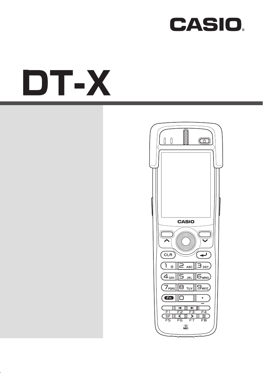
Handheld Terminal
E
User’s Guide
Be sure to read “Safety
Precautions” inside this
guide before trying to use
your Handheld Terminal.
100
Series
Page 2

Bluetooth is a registered trademark owned by Bluetooth SIG, Inc. and licensed to CASIO
•
COMPUTER CO., LTD.
Microsoft and Windows are either registered trademarks or trademarks of Microsoft
•
Corporation in the United States and/or other countries.
Information in this document is subject to change without advance notice. CASIO Computer Co.,
Ltd. makes no representations or warranties with respect to the contents or use of this manual
and specifi cally disclaims any express or implied warranties of merchantability or fi tness for any
particular purpose.
Page 3

Contents
Safety Precautions .........................................................................................E-3
Operating Precautions ...................................................................................E-7
Important .........................................................................................................E-9
Regulatory Information ..................................................................................E-9
Handheld Terminal System Confi guration .................................................E-10
General Guide ...............................................................................................E-11
Loading and Removing the Battery Pack ...................................................E-14
Loading ..............................................................................................................E-14
Removing ........................................................................................................... E-16
Attaching the Hand Strap ............................................................................E-17
Setting up ......................................................................................................E-18
Using the Mouse Emulator Function ................................................................. E-18
Adjusting Display Brightness ............................................................................E-20
Display Auto Dimmer ........................................................................................E-20
Using the Laser Scanner (DT-X100-10E) ....................................................E-21
Warning Label .................................................................................................... E-22
Bar Code Scanning Position ..............................................................................E-22
Adjusting the Laser Light Emission Width .................................................E-23
Using the C-MOS Imager (DT-X100-20E)....................................................E-25
Warning Label .................................................................................................... E-26
Bluetooth
Resetting the Handheld Terminal ................................................................E-28
Performing a Full Reset (Initialization) ............................................................ E-29
DT-X100 Specifi cations ...............................................................................E-30
®
Communication ...............................................................................E-27
E-1
Page 4

Using the USB Cradle (HA-F60IO/HA-F60IOA) ..........................................E-34
General Guide .................................................................................................... E-34
Connecting the USB Cradle Power Supply .......................................................E-36
Specifi cations ..................................................................................................... E-39
Using the Ethernet Cradle (HA-F62IO/HA-F62IOA) ...................................E-40
General Guide .................................................................................................... E-40
Connecting the Ethernet Cradle Power Supply .................................................. E-42
Specifi cations ..................................................................................................... E-45
Using the Cradle-type Battery Charger (HA-F30CHG) ..............................E-46
General Guide .................................................................................................... E-46
Connecting the AC Adaptor for Cradle-type Battery Charger ........................... E-47
Specifi cations ..................................................................................................... E-49
Using the Cradle-type Dual Battery Charger (HA-F36DCHG) ..................E-50
General Guide .................................................................................................... E-50
Charging Battery Pack ....................................................................................... E-52
Connecting Multiple Cradle-type Dual Battery Chargers .................................. E-53
Specifi cations ..................................................................................................... E-54
Using the Dual Battery Charger (HA-F32DCHG)........................................E-56
General Guide .................................................................................................... E-56
Charging Battery Pack ....................................................................................... E-58
Connecting Multiple Dual Battery Chargers......................................................E-59
Specifi cations ..................................................................................................... E-60
Using Rechargeable Battery Pack ..............................................................E-61
Battery Pack Specifi cations ................................................................................ E-62
Large-capacity Battery Pack Specifi cations ....................................................... E-62
Attaching the Hand Belt (HA-F95HB) ..........................................................E-63
Attaching the Hand Belt .....................................................................................E-63
E-2
Page 5
Safety Precautions
Congratulations upon your selection of this CASIO product. Be sure to read the
following Safety Precautions before trying to use it for the fi rst time.
Your neglect or avoidance of the warning and caution statements in the
subsequent pages causes the danger of fi re, electric shock, malfunction and
damage on the goods as well as personal injury.
Markings and Symbols
The following are the meanings of the markings and symbols used in these Safety
Precautions.
Danger
Warning
Caution
A diagonal line indicates something you should not do. The symbol shown
•
here indicates you should not try to take the unit apart.
A black circle indicates something you should do. The symbol shown here
•
indicates you should unplug the unit from the wall outlet.
This symbol indicates information that, if ignored or applied
incorrectly, creates the danger of death or serious personal injury.
This symbol indicates information that, if ignored or applied
incorrectly, creates the possibility of death or serious personal
injury.
This symbol indicates information that, if ignored or applied
incorrectly, creates the possibility of personal injury or property
damage.
Disassembly and Modifi cation
Never try to disassemble or modify the Handheld Terminal and its options
•
including battery pack and battery in any way.
Abnormal Conditions
Should the Handheld Terminal and/or its options including battery pack and
•
battery become hot or start to emit smoke or a strange odor, immediately turn
off the power and contact your dealer or distributor whom you purchased the
product from, or an authorized CASIO service provider.
Warning
E-3
Page 6
Warning
Dust and Moisture
Though the Handheld Terminal is dust and water splash resistant, its options
•
including the battery pack are not. Keep loose metal objects and containers
fi lled with liquid away from your Handheld Terminal and the options. Also,
never handle the Handheld Terminal and the options while your hands are wet.
Laser Light
This product uses laser light for aiming a bar code. Never look directly into
•
the laser light or shine the laser light into the eyes.
Warning
Interference with the Operation of Other Equipment
(Using Wireless Data Communication)
Keep your Handheld Terminal well away from anyone wearing a
•
pacemaker. Radio waves emitted by the Handheld Terminal can affect the
operation of a pacemaker.
Before the use in aircraft, be sure to consult with cabin crew for interference
•
the Handheld Terminal emits.
Before the use in medical facility, be sure to consult with the facility
•
management or the manufacture of a specifi c medical equipment that the
Handheld Terminal may interfere with.
Do not use the Handheld Terminal nearby gas pump or chemical tank or any
•
other places fl ammable or explosive.
E-4
Foreign Objects
Take care to ensure that metals or combustible objects are not inserted into
•
the openings of the Handheld Terminal or its options, and not to allow
moisture to get inside of them.
Location
Install the cradle properly on a fl at and stable surface so that it cannot fall
•
down onto fl oor.
Do not leave the Handheld Terminal and its options for a long period in a
•
car parked in direct sunlight.
LCD Screen
Never apply strong pressure to the screen or subject it to strong impact.
•
Doing so can crack the LCD Screen.
Low Temperature Burn
Avoid prolonged contact with the skin while the Handheld Terminal is
•
switched on. Some areas on the back of the Handheld Terminal may
become hot during use and could cause low-temperature burns.
Caution
Page 7
Optional Lithium-ion Battery Pack
Danger
Never use the Handheld Terminal and its option including the battery pack
•
and battery next to open fl ame, near a stove, or any other area exposed to
high heat, or leave them for a long period of time in a vehicle parked in
direct sunlight.
Never use the battery pack with any device other than the Handheld
•
Terminal.
Never dispose of the battery pack by incinerating it or otherwise expose it
•
to heat.
Never transport or store the battery pack together with metal objects that
•
may result in shorting positive (+) and negative (–) terminals of the battery
pack. Be sure to place the battery pack in its case whenever transporting or
storing it.
Never throw the battery pack or otherwise subject it to strong impact.
•
Never pierce the battery pack with nails, hit it with a hammer, or step on it.
•
Use only the specifi ed battery charger to charge the battery pack.
•
Warning
Never place the battery pack in a microwave oven or any other high-voltage
•
device.
If the amount of time period the battery pack can serve becomes
•
considerably short even after it has been fully charged for the specifi ed time
period, stop using it.
Should the battery pack start to leak or emit a strange odor, immediately
•
move it away from any nearby fl ame. Leaking battery fl uid is combustible.
Should fl uid from the battery pack accidentally get into your eyes or on the
•
skin, do not rub it. Immediately rinse it off with clean tap water and then
consult a physician.
Caution
Replace only with the same type of battery pack recommended by CASIO.
•
Dispose of used battery packs according to the local regulation.
Keep the battery pack out of the reach of small children.
•
Risk of explosion if battery is replaced by an incorrect type. Dispose of
•
used batteries according to the instructions.
E-5
Page 8
Power Supply / AC Adaptor
Do not use the Handheld Terminal at a voltage other than the specifi ed voltage.
•
Also, do not connect the Handheld Terminal to a multi-plug power strip.
Never modify, sharply bend, twist, or pull on the power cord.
•
Never use a detergent to clean AC adaptor and its power cable, especially
•
on the plug and the jack.
Do not use an AC adaptor with a bent connector.
•
Do not twist or wrench the connector.
•
When using the battery chargers and the cradles, be sure to use the
•
respective AC adaptors.
Never pull on the power cord when unplugging it. Always hold the plug
•
when unplugging it from the wall outlet.
Never touch the plug while your hands are wet.
•
Be sure to unplug the power cord from the wall outlet before cleaning the
•
battery chargers and the cradles.
Unplug the power cord from the wall outlet whenever leaving the battery
•
chargers and the cradles unattended for a long period.
The housing of the AC adaptor can become warm during normal use.
•
At least once a year, unplug the AC adaptor from the wall outlet and clean
•
any dust that builds up between the prongs of the plug.
Dust built up between the prongs can lead to the danger of fi re.
Check that the connector is properly oriented and then push it straight in (do
•
not insert upside down).
Do not allow fl uids or foreign objects to get into the AC adaptor.
•
Choose a location where the power cord is readily accessible and can be
•
easily plugged in and unplugged.
When using the AC adaptor, always use a power outlet with the specifi ed
•
power supply and voltage, and ensure that the power plug is inserted into
the socket fully and securely.
Warning
Caution
Backup of All Important Data
Note that CASIO Computer Co., Ltd. shall not be held liable to you or any
•
third party for any damages or loss caused by deletion or corruption of data
due to use of the Handheld Terminal, malfunction or repair of the Handheld
Terminal or its peripherals, or due to the batteries going dead.
The Handheld Terminal employs electronic memory to store data, which
•
means that memory contents can be corrupted or deleted if power is
interrupted due to the batteries going dead or incorrect battery replacement
procedures. Data cannot be recovered once it is lost or corrupted. Be sure
to make backup of all important data. One way to do this is to use the
separately sold cradles to transfer data to a computer.
E-6
Caution
Page 9

Use Casio genuine battery pack only
Danger
We recommend the use of Casio genuine battery packs with Casio devices.
•
Casio genuine battery packs are tested for quality and safety for the safe use of
the product they are installed. We cannot be held liable for accidents or damages
caused by counterfeit Casio battery packs or battery packs other than Casio
genuine battery packs. When buying a battery pack, pay due attention to buy a
Casio genuine battery pack.
Operating Precautions
Your Handheld Terminal and its options are precision. Improper operation or rough handling can
cause problems with data storage and other problems. Note and observe the following precautions
to ensure proper operation.
Do not continue operating the Handheld Terminal when battery power is low.
•
Doing so can cause data to be lost. When the battery goes low, charge it as soon as possible.
Do not leave dead battery pack in the Handheld Terminal for a long period.
•
Dead battery pack can leak, leading to malfunction and damage to the Handheld Terminal.
Use the Handheld Terminal and its options only within the specifi ed temperature range.
•
Use outside of the specifi ed temperature range creates the risk of malfunction.
Avoid using the Handheld Terminal and its options in areas subject to the following conditions.
•
The following conditions create the risk of damage to the Handheld Terminal.
— Large amounts of static electricity
— Extreme heat or extreme cold
— High humidity
— Sudden temperature extremes
— Large amounts of dust
Do not use volatile chemical substances such as thinners, benzene or toiletries to clean the
•
Handheld Terminal.
When the Handheld Terminal is dirty, wipe it clean with a soft, dry cloth. Rubbing with
excessive force could scratch the display.
The power-supply terminals and Data Communication terminals should be cleaned from
•
time to time using an implement such as a dry cotton bud.
Soiling on the terminals may cause connection defects.
Take care when using chemicals.
•
Applying thinners, gasoline, kerosene, solvents or oils, or substances such as cleaners,
adhesives, paints, medications or toiletries that contain those materials, to the plastic case or
cover may cause discoloration or other damage.
The back of the Handheld Terminal may become hot during use. This is normal and does
•
not indicate a fault.
E-7
Page 10

802.11a/n Restrictions:
•
— This product is for indoor use only when using channels 36, 40, 44, 48, 52, 56, 60, or 64
(5150-5350 MHz).
— To ensure compliance with local regulations, be sure to select the country in which the
access point is installed
Although the Handheld Terminal meets the IP54 level of the International Standard
•
IEC60529, pay your attention to the following when using it in the rain.
— After a large amount of rain or water falls on the Handheld Terminal, wipe off it immediately.
— Do not use it in the rain for a long period of time.
— Make sure the battery cover and connect cover are closed securely before using it.
— Do not press on the screen or keys with excessive force when using it in the rain.
Dead Pixels
•
The LCD panel employed in this product uses high precision and substantial number of components
which commonly cause a small number of the pixels not to light or to remain lit all the time. This is
due to the characteristics of LCD panel yield in accuracy over 99.99% and permissible.
Lithium-ion Battery Pack
•
Each lithium-ion battery pack has its life. The life span heavily depends on how the
battery pack is charged or stored which may cause deterioration of the battery pack
to shorten the life span if it is handled improperly. Note the tips below to make the
battery pack last long.
— Be sure to charge the battery pack before using it if the battery pack is used for the
fi rst time or if it has not been used for a long period of time.
— If the battery pack is repeatedly charged, the life span becomes short. To avoid the
repetition of charging the battery pack, be sure that the remaining capacity is low
before you start charging.
— Be sure to charge the battery pack in recommended temperature range. The
temperature range is dependant on device you use to charge including battery
chargers and Handheld Terminals. Refer to the respective user guides. Charging
the battery pack in a temperature outside of the recommended range causes
deterioration.
— When used at low temperatures, the battery pack has a reduced capacity and will
supply power for shorter time.
The life span of the battery pack is also shortened.
— Charging the battery pack while the battery pack itself is freeze including inside
causes deterioration. Be sure to resume an ordinary room temperature on the
battery pack and then leave it unattended for approximately one hour before
charging.
— After charging the battery pack, if the performance of the battery pack does not
show any recovery, it is a sign of ending the life. Replace it with a new battery
pack.
— Avoid the battery pack with a full of the capacity to store for a long period of
time. If you need to store it for a long period, be sure that the remaining capacity
is 30 to 50 percent and to store in a moderate low temperature. This can reduce
deterioration.
E-8
Page 11
— The battery pack gradually deteriorates over time. In particular, storing (or using)
the fully charged battery pack at high temperatures tends to accelerate battery
pack deterioration.
Important
This guide does not include any information about programming and download
•
procedures. See the applicable separate documentation for information about the
procedures.
After Service
Should this product ever malfunction, contact your original retailer providing
•
information about the product name, the date you purchased it, and details about the
problem.
Regulatory Information
Europe
DT-X100
Options of DT-X100
Please keep all information for future reference.
•
The declaration of conformity may be consulted at http://doc.casio.com
•
Products are for distribution within all member states of the EU.
•
Options of DT-X100 are HA-F60IOA, HA-F62IOA, HA-F30CHG, HA-F32DCHG,
•
HA-F20BAT, HA-F21LBAT, AD-S42120C-N5, AD-S15050B-N5, DT-380USB-A and
AC-CORD-EU
Manufacturer:
CASIO COMPUTER CO., LTD.
6-2, Hon-machi 1-chome, Shibuya-ku, Tokyo 151-8543, Japan
Responsible within the European Union:
Casio Europe GmbH
Casio-Platz 1, 22848 Norderstedt, Germany
www.casio-europe.com
Maximum radio output power
IEEE802.11a/b/g/n: 2.4GHz band 20dBm; 5GHz band 14dBm.
•
Bluetooth: 2.4GHz 4dBm.
•
Hereby, CASIO COMPUTER CO., LTD. declares that the radio equipment type DT-X100 is
in compliance with Directive 2014/53/EU.
E-9
Page 12
Handheld Terminal System Confi guration
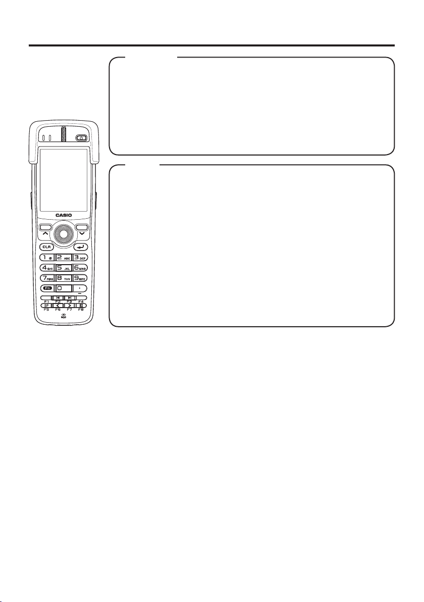
Accessories
Please check the contents in the box before using the Handheld
Terminal for the fi rst time.
The Handheld Terminal comes with the standard battery pack cover
and protector already fi tted.
DT-X100 SeriesDT-X100 Series
• Hand Strap
• Large-capacity Battery Pack Cover
• User's Guide
Options
• USB Cradle HA-F60IO*/HA-F60IOA
• Ethernet Cradle HA-F62IO*/HA-F62IOA
• Cradle-type Battery Charger HA-F30CHG
• Cradle-type Dual Battery Charger HA-F36DCHG
• Battery Pack HA-F20BAT
• Large-capacity Battery Pack HA-F21LBAT
• Dual Battery Charger HA-F32DCHG
• AC Adaptor for USB Cradle/Ethernet Cradle/
Dual Battery Charger AD-S42120C
• AC Adaptor for Cradle-type Battery Charger AD-S15050B
• AC Adaptor for Cradle-type Dual Battery Charger AD-S60160B
• Power Cord AC-CORD
• Cable DT-380USB-A
• Hand Belt HA-F95HB
* Not sold in the EU or in EFTA member states.
*
*
For the latest options list, refer to the ON-LINE manual available at
http://support.casio.com/en/manual/manual.php?cid=010
E-10
Page 13
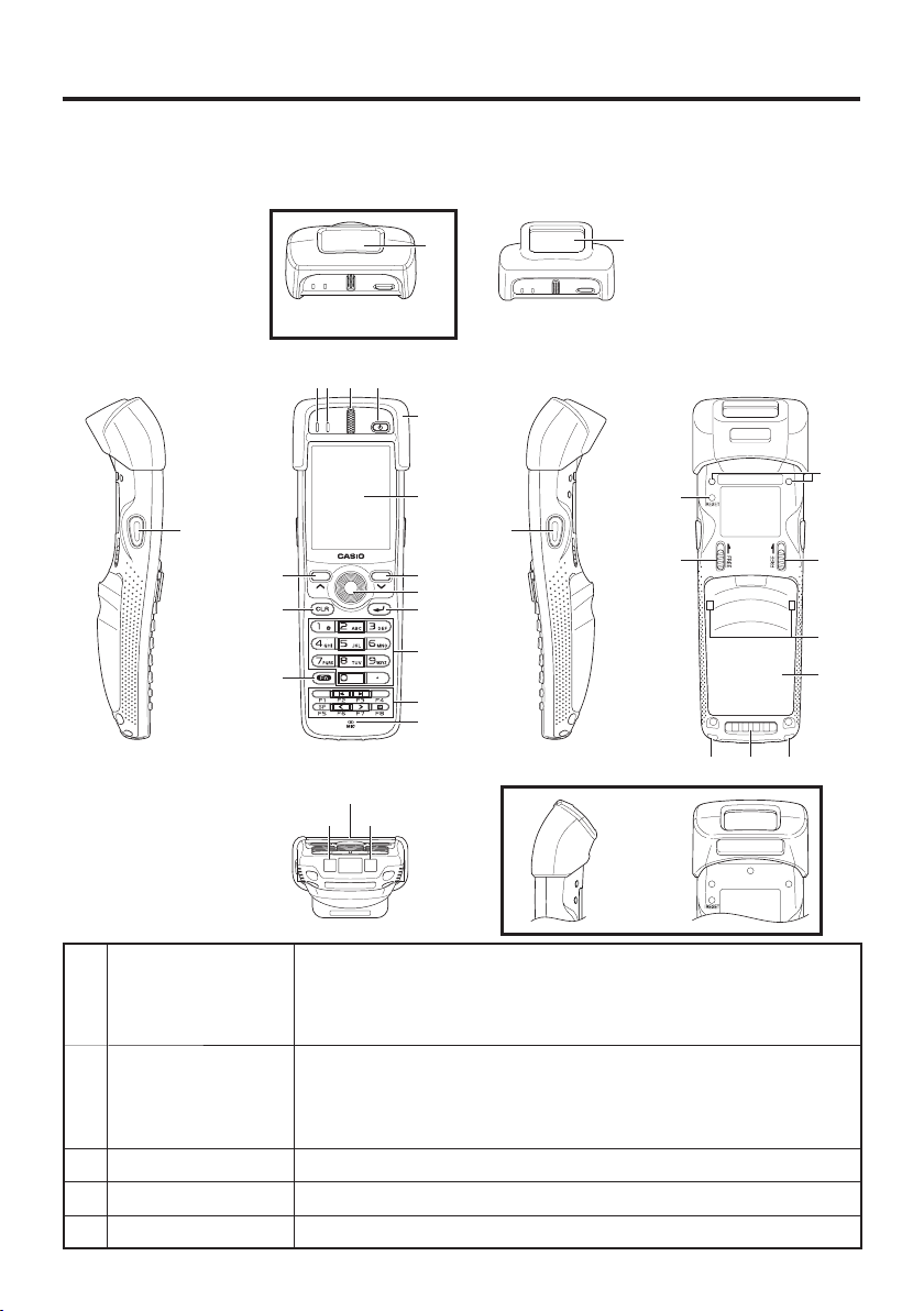
General Guide
Handheld Terminal (DT-X100)
TOP
17
DT-X100-10E
17
DT-X100-20E
Left Front Right Back
4321
5
6
16
8
12
11
8
7
9
10
13
14
Bottom
191819
15
DT-X100-10E
22
24
21 20 21
23
24
26
25
1 Indicator 1 Orange: Charging the battery pack.
Green: Charging the battery pack is complete.
Red: Battery pack error or the surrounding temperature is out of
the charging temperature range.
2 Indicator 2 Flashes in blue when operating via Bluetooth or in orange when
operating via WLAN. Lights in green when reading a bar code
successfully. Flashes magenta when the DT-X100 is connected
to a PC by the USB.
3 Speaker Buzzer and voice messages are output here.
4 Power Key Turns the power on and off.
5 Protector Fitted on the Handheld Terminal.
E-11
Page 14

6 Screen Displays text and operating instructions.
7 Trigger Center Key Used to perform bar code reading. Can be assigned an arbitrary
function.
8 Cursor Keys Perform the same functions as the up and down arrow keys on a
PC keyboard.
9 Enter Key Press when fi nishing entering numerical values or when moving
to the next step.
10 Numeric Keys Used to enter numeric values and decimal points.
11 Fn Key Used to make various settings in combination with the function
keys or numeric keys or when starting a pre-registered
application.
12 CLR Key Used to clear one letter to the left of the cursor.
13 Function Keys Various functions other than bar code reading can be assigned to
these keys.
The default key assignments are as follows.
F1: Similar function as the Alt key on a PC keyboard.
F2: Similar function as the Shift+Tab keys combination on a PC
keyboard. Used to move the cursor among entry or selection
items.
F3: Similar function as the Tab key on a PC keyboard. Used to
move the cursor among entry or selection items.
F4: Not assigned.
F5: Enter a space.
F6: Similar function as the cursor left key on a PC keyboard.
F7: Similar function as the cursor right key on a PC keyboard.
F8: Select text entry mode.
(The mode changes in order of Numeric ➝ Uppercase letter ➝
Lowercase letter)
14 Microphone Used to input a sound including voice.
15 Trigger R Key Used to perform bar code reading.
16 Trigger L Key Used to perform bar code reading.
17
Barcode Reader Port
18 IR Port Used for communication with another Handheld Terminal.
19 Power Contacts Used to receive power provided by the USB Cradle or Ethernet
20
Data Communication
Terminal
Laser light or LED light is emitted from this window that reads
bar codes.
Cradle.
Used for data communications.
E-12
Page 15

21 Strap Holes Used to attach the hand strap. Also used for the hand belt.
22 Reset Switch Used to reset the Handheld Terminal.
23 Hand Belt Holes Used to attach the hand belt.
24 Battery Pack Cover
Lock Switch
25 Battery Pack Cover Used to cover the battery compartment that holds the battery
26 Mount Holes These holes hold the terminal seating in the optional USB
Used to lock the battery cover and to release.
pack inside.
Cradle or in the Ethernet Cradle.
E-13
Page 16

Loading and Removing the Battery Pack
Your Handheld Terminal uses two types of battery: a battery pack and a memory
backup battery.
The battery pack is used to power normal operations and to store data, while the
memory backup battery provides the power required to maintain memory contents
when the battery pack power is unable to supply power for some reason.
The operating power is supplied by a battery pack. You can choose between a battery
(HA-F20BAT) and a large-capacity battery pack (HA-F21LBAT).
pack
The backup battery is installed inside of the Handheld Terminal.
This guide uses the following terms to refer to the batteries.
Battery Pack: Rechargeable battery pack (HA-F20BAT or HA-F21LBAT) for
normal operations and data storage
Backup Battery: Built-in battery for memory backup
When the battery pack power goes low, immediately charge it or replace it with a
charged battery pack.
You can use the Dual Battery Charger, the Cradle-type Battery Charger, the Cradle-type
Dual Battery Charger, the USB Cradle, or Ethernet Cradle to charge a battery pack. See
the sections of this guide that cover the Dual Battery Charger, the Cradle-type Battery
Charger, the Cradle-type Dual Battery Charger, the USB Cradle, and the Ethernet
Cradle for information about how to use them for charging.
Important!
Always keep backup copies of all important data!
The battery pack powers normal operation and also provides power required to
•
maintain memory contents, while the backup battery provides backup power to
maintain memory contents. Because of this, you should not remove the battery
pack if the backup battery is dead. Removing the battery pack while the backup
battery is dead causes data in the memory to be corrupted or lost. Note that
once data is lost it cannot be recovered. Always keep separate backup copies of
all important data.
The charge of a battery pack when you purchase it may be depleted due to
•
testing at the factory or natural discharge during shipment and storage. Be sure
to charge the battery pack before you use it.
The life of a battery pack is limited, and charging a battery pack causes it to
•
gradually lose its ability to maintain the charge. If your battery pack seems to
require charging very frequently, it probably means it is time to purchase a new one.
If a battery pack is used past the end of its service life, it may swell up in size. In
•
such a case, replace the battery pack with a new one.
If the backup battery is fully charged, it will maintain the contents of the
•
terminal’s memory (RAM) for approximately 10 minutes when the main battery
pack is removed.
It takes 4 days with the main battery pack installed in the terminal for the
•
backup battery to be charged fully.
Loading
1. Turn over the Handheld Terminal.
2. Remove the rechargeable battery pack cover as follows:
Slide the left and right lock switches for the rechargeable battery pack cover
simultaneously in the direction indicated by the arrows.
E-14
Page 17
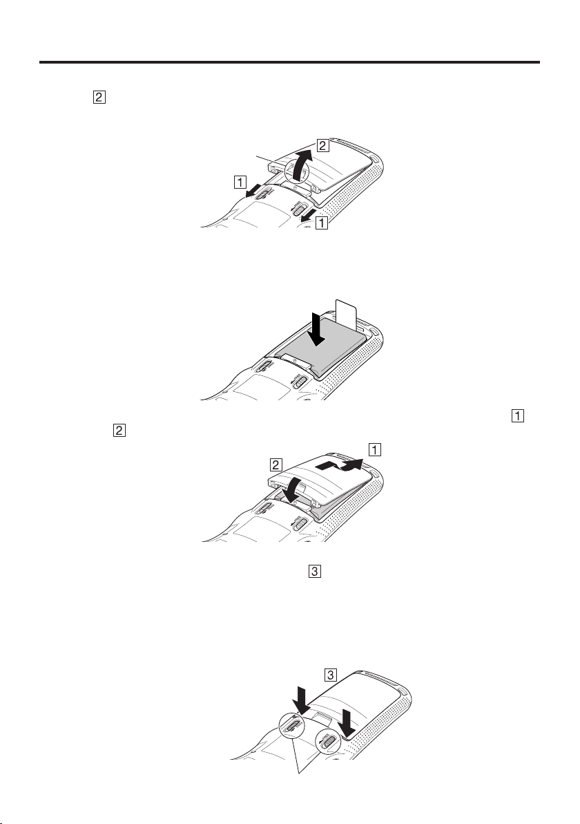
While holding the switches back, hook your fi ngertip into the notch in the
rechargeable battery pack cover and lift the cover up in the direction indicated by
the arrow.
Notch
3. Load a battery pack (HA-F20BAT) or large-capacity battery pack (HA-F21LBAT).
Take care that the battery pack is oriented correctly when you load it. In addition,
load the battery back while making sure that the end of the battery pack removal tape
is protruding above the battery pack.
4. Put back the battery pack cover in the compartment as instructed by the arrows,
in the illustration.
and
After putting back the cover, fi rmly press the cover so that it is locked in the position by
the two Battery Pack Cover Lock Switches
Ensure that both the switches returned all the way down to the home positions as
•
.
indicated by the two arrows.
If the switches are lackadaisically positioned, it causes the switches not to activate.
When loading a large-capacity battery pack, use the large-capacity battery cover instead
of the standard battery cover.
BatteryPackCoverLockSwitches
E-15
Page 18
Removing
1. Make sure that the Handheld Terminal is turned off.
If the power is on, press the power key to turn it off.
2. Turn over the Handheld Terminal.
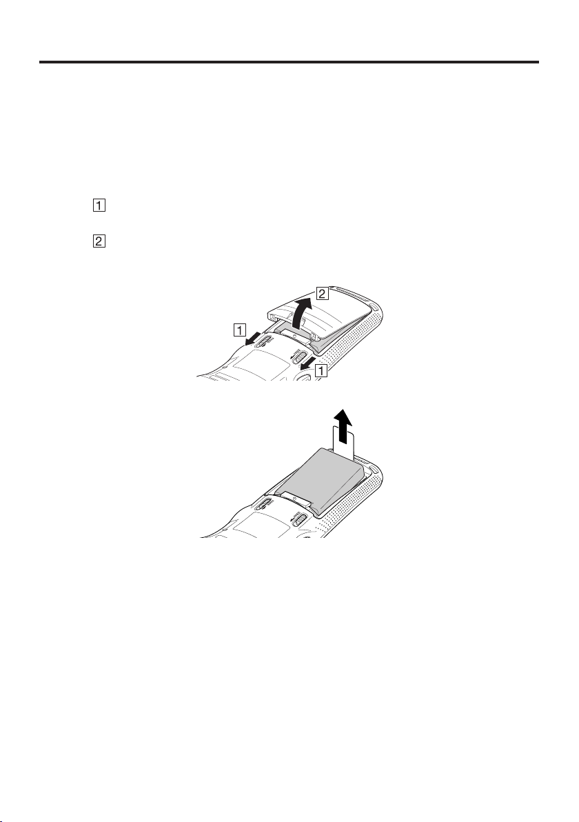
3. Remove the rechargeable battery pack cover as follows:
Slide the left and right lock switches for the rechargeable battery pack cover
simultaneously in the direction indicated by the arrows.
While holding the switches back, hook your fi ngertip into the notch in the
rechargeable battery pack cover and lift the cover up in the direction indicated by
the arrow.
4. Remove the battery pack by pulling up the removal tape as shown in the illustration.
E-16
Important!
When removing the battery pack, make sure you do not leave the Handheld
•
Terminal without a battery pack for more than about 10 minutes. Doing so can
cause data in the memory to be deleted.
When removing the battery pack, be sure you carefully follow the proper
•
procedure as explained in this guide.
Never try to use other type of battery than the ones that are specifi ed for this
•
product.
When removing the battery pack, pull the removal tape straight up and remove
•
the battery pack. Removing with excessive force can damage the battery pack.
Before starting to use the DT-X100, ensure that the battery pack cover is
•
properly closed. If not, the power cannot be turned on or is turned off abruptly
while the DT-X100 is in use.
Page 19
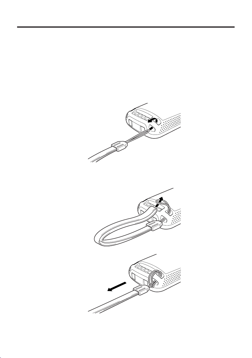
Attaching the Hand Strap
The hand strap can be used to prevent the Handheld Terminal from dropping when
carrying it around. Since there are two strap holes where the hand strap can be attached,
use the hole that affords the ease of use. Attach the hand strap according to the
procedure described below.
To attach the hand strap
1. Pass the thin cord of the hand strap through the hand strap hole on the back of the
Handheld Terminal.
2. Pass the other end of the strap (the part you put around your hand) through the loop
formed by the thin cord.
Important!
Do not swing the Handheld Terminal around holding the hand strap.
E-17
Page 20
Setting up
Using the Mouse Emulator Function
The mouse emulator function lets you make settings and adjustments by using a mouse
cursor.
To use the mouse cursor, fi rst set up the mouse emulation mode by following the below
procedure.
In the emulation mode, the numeric keys and Trigger R key are used to manipulate
the mouse cursor. (In the emulation mode, the numeric keys and Trigger R key
cannot be used for entering numerics and scanning bar codes respectively.)
Activating the mouse emulator function
■
•
While no mouse cursor is shown on the screen, press the “Fn” key followed by the
“4” key. The mouse cursor appears, and the mouse emulator function is now active.
*
To turn off the function, press the same key sequence again, i.e. “Fn” key ➝ “4” key.
*
Each push of this key toggles the function between on and off.
Using the mouse cursor
■
Activate the mouse emulator function as described above.
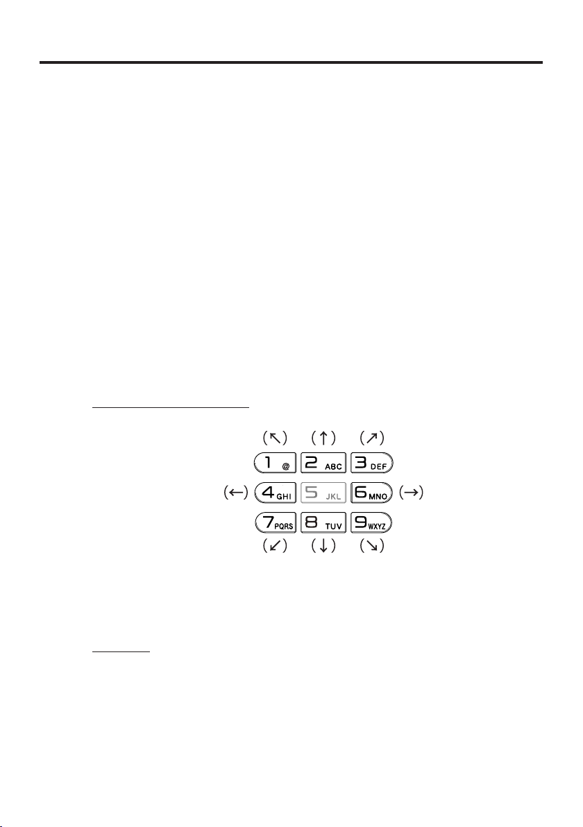
Mouse cursor movement
•
Press a numeric key for the direction in which you want to move the mouse cursor.
E-18
Mouse cursor moves
in the arrow direction.
* Holding down a key moves
the mouse cursor continuously.
Left click
This serves for selecting a fi le, making a menu selection, or a similar action.
Move the mouse cursor to the position where you want to click, and press the “5”
•
key.
Page 21

Right click (calling up a menu)
•
Move the mouse cursor to the position where you want to click, and press the
Trigger R key.
Left double click
Performing this action while the mouse cursor is on an icon starts an application,
opens a fi le, etc.
•
Move the mouse cursor to the position where you want to double click, and press
the “5” key twice.
*
The double click timing follows the double tap setting of Windows CE. The setting
can be changed by accessing the “Mouse” icon in the Control Panel.
Dragging
This action allows you to move an application icon on the screen or a fi le or folder in
File Explorer.
•
Move the mouse cursor to the position where you want to start dragging, and press
the “5” key. Then move the mouse cursor by holding down the “5” key and pressing
another numeric key for the direction in which you want to move. The selected item
will be dragged along with the cursor. When you release the “5” key, the item is
dropped at the current location.
E-19
Page 22

Adjusting Display Brightness
You can use the following procedure to adjust display brightness to make it easier to
read under different lighting conditions.
Press the “Fn” key and then press the “5” key or “6” key after confi rming that “F”
•
is displayed in the lower right corner of the screen. Pressing the “5” key adjusts
brightness for a darker display, while pressing the “6” key adjusts brightness for a
lighter display.
In order to continue to make adjustments, press the “5” key or “6” key after pressing
*
the “Fn” key.
Display Auto Dimmer
The display auto dimmer automatically lowers display brightness if you do not perform
any operation for a specifi c period of time. This helps the battery power to be
conserved.
You can use the following procedure to specify a period of time that should be allowed
to elapse until when the auto dimming is initiated.
1. Use the “
key. Then navigate to Settings ➝ Control Panel with the Enter
key to bring up the Control Panel.
”/“ ” keys to move the focus to the [Start] icon and press the Enter
2. Move the focus to the “Brightness” icon and press the
Enter key. Then use the “
focus to the tabs and use the “<”/ “>” keys to select the
[Backlight] tab. Adjust the displayed items.
The mouse emulator function can also be used to make
*
the adjustment.
”/“ ” keys to move the
E-20
Focus
Page 23

Using the Laser Scanner (DT-X100-10E)
1. After turning on the power, position the laser scanner close to a bar code and then
press the trigger key.
2. The laser emits light and scans the bar code. If scanning is completed normally,
Indicator 2 displays a green light and a buzzer sounds.
Important!
If you are unable to scan a bar code, try changing the angle at which the scanner
•
is held or distance from the scanner to the bar code, and then try scanning
again.
This Handheld Terminal is capable of scanning bar codes at a distance of
•
about 40-550 mm. Furthermore, the distance at which scanning is possible may
vary according to the bar code symbology.
E-21
Page 24

Warning Label
This label is a warning and caution label for Class 2 laser products that comply
•
with IEC60825-1:2014.
Although Class 2 laser light is only emitted momentarily, never look directly into
•
the beam light.
The laser light emitted by this laser scanner has a maximum output of less than
•
1 mW and a wavelength of 650 nm.
Use of controls or adjustments or performance of procedures other than those
•
specifi ed herein may result in hazardous radiation exposure.
Bar Code Scanning Position
Position the laser scanner close to the bar code when scanning small bar codes.
Position the laser scanner at a distance from the bar code so that the bars enter the light
when scanning large bar codes.
E-22
Margin Margin
Good
Bad
Good Good
Bad Bad Bad
Warning!
Never look directly into the laser light.
■
The products with the integrated Laser Scanner module scan bar codes using
•
laser light. Never look directly into the laser light or shine the laser light
into the eyes.
Page 25

Adjusting the Laser Light Emission Width
The emission width of the laser light emitted by the Handheld Terminal can be adjusted.
Adjust the emission width when it has been changed.
The mouse emulator function can also be used to make the adjustment.
*
1. Use the “
icon and press the Enter key. Then navigate to Settings
Control Panel with the Enter key to bring up the
➝
Control Panel.
2. Move the focus to the [Scanner Setting] icon and press
the Enter key. The display appears as shown at right.
3. Use the “
and use the “<”/“>” keys to select the [Others] tab.
”/“ ” keys to move the focus to the [Start]
”/“ ” keys to move the focus to the tabs
E-23
Page 26

4. Use the “ ”/“ ” keys to move the focus to
[Calibration] and press the Enter key. The message
appears as shown at right.
5. Press the Trigger Key to emit laser light, and align the
light with the barcode for adjusting emission width.
Align the laser light with the narrow bars on both sides.
•
The message appears as shown at right when adjustment
•
is completed.
Repeat the setting if “Setting failed” message appears.
•
Emission Width Adjustment Bar Code
E-24
Page 27

Using the C-MOS Imager (DT-X100-20E)
1. Turn on the Handheld Terminal, position its C-MOS Imager reader port near the bar
code or 2D code, and then press the Trigger Key.
2. The Handheld Terminal reads the code by emitting laser and red lights.
Indicator 2 (read operation indicator lamp) lights in green when the reading is
successful.
Bar code and stacked 2D code Reading Guide
When you press the Trigger key, LEDs in the Handheld Terminal emit laser and red
lights. Align the laser frame with the center of the bar code or 2D code you are trying
to read. Take particular care aligning the light when there are other bar codes nearby.
When reading a bar code in large size, adjust the position of the Handheld Terminal
so that the entire code is enclosed within the laser frame. For small size, move the
Handheld Terminal closer to it.
Important!
If you have problem not properly reading a code, change the angle and/or the
•
distance between the code and the Handheld Terminal and try reading it again.
A bar code can be read from a distance of 45mm to 400mm, and a stacked 2D
•
code can be read from a distance of 40mm to 230mm and matrix 2D code can be
read from a distance of 48mm to 300mm. The actual reading distance depends
on the symbology and the resolution.
Note that a special reader application is required to read bar codes and 2D
•
codes.
Fingerprints, dust, dirt, or stain on the C-MOS Imager reader port can cause
•
abnormal reading. Should the reader port become dirty, wipe it clean with a soft
and dry cloth.
E-25
Page 28

Warning Label
This label is a warning and caution label for Class 2 laser products that comply
•
with IEC60825-1:2014.
Although Class 2 laser light is only emitted momentarily, never look directly into
•
the beam light.
The laser light emitted by this laser scanner has a maximum output of less than
•
1 mW and a wavelength of 650 nm.
Use of controls or adjustments or performance of procedures other than those
•
specifi ed herein may result in hazardous radiation exposure.
Warning!
Never look directly into the laser light.
The products with the integrated C-MOS Imager module scan bar codes
•
using laser light. Never look directly into the laser light or shine the laser
light into the eyes.
E-26
Page 29

Bluetooth® Communication
Bluetooth® interface can also be used to transmit data between two Handheld Terminals.
With Bluetooth
3
8
'10
"
(9
⁄
Important!
Observe the following precautions to help ensure that Bluetooth communication is
successful.
Make sure there is at least two meters (6'7") between the Handheld Terminal and
•
other equipment (electrical appliances, audio-visual equipment, OA equipment,
and digital cordless telephones, facsimile machines, etc.). (Take special care with
microwave ovens. Allow at least three meters (9'10
Terminals in wireless operation and a microwave oven.) When approaching such a
device when its power is turned on, proper communication may prove impossible
while this may also cause interference with TV and radio reception (images
produced by certain UHF and broadcast satellite channels may become blurry).
Normal communication may not be possible in an area near a broadcast trans-
•
mitter or wireless transmitter. If this happens, move the Handheld Terminal to a
different location. Normal communication may not be possible in areas exposed
to strong radio waves.
RF Wireless LAN Interference
•
Because Bluetooth
(2.4GHz), radio interference can occur if there is a wireless LAN device nearby.
This can result in lower communication speeds, or even make it impossible to
establish a connection. If this happens, try the following countermeasures.
Move at least 10 meters (32
•
If you cannot keep the distance at least 10 meters (32
•
Handheld Terminal and a wireless LAN device, turn off the power of either the
Handheld Terminal or the wireless LAN device.
Although the Handheld Terminal enables wireless LAN and Bluetooth
•
communication to be used simultaneously as a result of being equipped with
Bluetooth
surrounding radio wave environment.
®
the two Handheld Terminals should be located within about three meters
) from each other, as long as there is nothing blocking the path between them.
3
8
) between the Handheld
⁄
®
and RF wireless LAN use the same frequency band
3
4
'10
"
) away from the wireless LAN device.
⁄
®
Ver.2.1, communication may not be possible depending on the
3
4
'10
"
) or more between the
⁄
®
E-27
Page 30

Resetting the Handheld Terminal
Resetting the Handheld Terminal is the same as restarting a PC. Performing a reset
causes all unsaved inputs and edits to be lost, but data that is already stored in the
memory as well as all settings should be unaffected.
Use reset to restore normal operation whenever the Handheld Terminal operates
abnormally due to misoperation or some other reason.
Use a stylus to press the reset switch on the back of the DT-X100.
This starts the reset operation.
*
Do not use a toothpick or pencil or other object
whose tip may break off when pressing the reset
switch. Otherwise there is a risk of damage.
E-28
Page 31

Performing a Full Reset (Initialization)
Performing a full reset initializes memory. This means that all data stored in the
memory (RAM) is deleted and all the settings are returned to their initial factory
settings.
Perform a full reset whenever any one of the following conditions exists.
When you want to delete all memory contents and return the settings to their initial
•
factory settings.
When you are no longer able to use the Handheld Terminal because you forgot your
•
password.
When the Handheld Terminal does not operate normally due to a memory problem.
•
When the message “A problem with memory contents has been found. ...” appears.
•
To perform a full reset
Important!
Performing a full reset deletes all data currently stored in the memory (RAM).
If possible, backup data of the Handheld Terminal to a PC, Flash Memory, a
memory card, or some other medium before performing a full reset.
1. While holding down the Power key and CLR key simultaneously, press the reset
swicth using stylus for approximately one second and then release the reset switch
fi rst. The message shown below appears.
To cancel the full reset operation, press the Trigger L key.
•
2. Press the Trigger R key. This causes the message shown below to appear.
To cancel the full reset operation, press the Trigger L key.
•
3. Press the Trigger R key again.
Full reset is performed, all data in the memory (RAM) are erased and the start-up
•
screen is displayed.
Trigger R
Key
Trigger R
Key
E-29
Page 32

DT-X100 Specifi cations
Model: DT-X100-10E, DT-X100-20E
CPU: Marvell
Memory: 256MB RAM, 512MB Flash ROM (user area: approx. 220MB)
OS: Microsoft
Display: 2.4-inch, 320
®
PXA320 806MHz
®
Windows® Embedded Compact7
240-dot transfl ective TFT color LCD
×
Laser Scanner (DT-X100-10E):
Readable symbologies: UPC-A/UPC-E/EAN8 (JAN8)/EAN13 (JAN13)/Codabar
(NW-7)/Code39/Interleaved2of5 (ITF)/MSI/Industrial2of5/
Code93/Code128 (EAN128)/IATA/GS1 DataBarOmnidirectional
(RSS-14)/GS1 DataBarLimited (RSS Limited)/GS1 DataBar
Expanded (RSS Expanded)/GS1 DataBar Stacked (RSS-14
Stacked)/GS1 DataBar Expanded Stacked (RSS Expanded
Stacked)/GS1 DataBar Truncated/GS1 DataBar Stacked
Omnidirectional (RSS-14 Stacked Omnidirectional)
Scanning distance: Within approximately 40-550 mm (19/16"-153/4")
C-MOS Imager (DT-X100-20E):
Readable symbologies: 1D: UPC-A/UPC-E/EAN8 (JAN8)/EAN13 (JAN13)/Codabar
(NW-7)/Code39/Interleaved2of5 (ITF)/MSI/Code93/Code128
(GS1-128 (EAN128))/Code11/GS1 DataBarOmnidirectional
(RSS-14)/GS1 DataBarLimited (RSS Limited)/GS1 DataBar
Expanded (RSS Expanded)/Code32/GS1 DataBar Truncated
(RSS-14 Truncated)/ISBT
Stacked 2D: PDF417/Micro PDF/Composite/Codablock
F/GS1 DataBar Stacked Omnidirectional (RSS-14 Stacked
Omnidirectional)/GS1 DataBar Expanded Stacked (RSS
Expanted Stacked)/GS1 DataBar Stacked (RSS-14 Stacked)/
GS1DataBar Truncated (RSS-14 Truncated)
Matrix 2D: Aztec, DataMatrix, Maxicode, QR Code, Micro QR
Scanning distance: 1D: 45 – 400 mm
Stacked 2D: 40 – 230 mm
Matrix 2D: 48 – 300 mm
Bluetooth
Protocol: Bluetooth
®
:
®
Specifi cation Ver.2.1+EDR
Range: Approximately 3 m (depends on radio wave conditions and
environment)
Output: 4dBm max. (PowerClass2)
WLAN:
Standards: IEEE 802.11a/b/g/n
Modulation Type: 802.11a/g/n:OFDM (OrthogonalFrequencyDivisionMultiplexing)
802.11b:DSSS (Direct Sequence Spread Spectrum)
BPSK, QPSK, CCK, 16QAM, 64QAM
E-30
Page 33

Frequency: <Center frequency>
Baud Rate: 802.11a/g : 54Mbps (maximum)
802.11b : 11Mbps (maximum)
802.11n : 65Mbps (maximum)
Communication Range: 802.11b/g/n :Approx.50m (indoor), Approx.150m (outdoor)
802.11a/n : Approx.50m (indoor), Approx.150m (outdoor)
Power Requirements:
Power Source: HA-F20BAT Battery Pack
HA-F21LBAT Large-capacity Battery Pack
Memory Backup: Rechargeable Lithium Battery (Built-in)
Consumption Current: DC 1.6A (DT-X100-10E)
DC 1.7A (DT-X100-20E)
Battery Life: Battery pack:
DT-X100-10E
Approximately 15 hours (HA-F20BAT)*
Approximately 26 hours (HA-F21LBAT)*
Approximately 10 hours (HA-F20BAT)**
Approximately 17 hours (HA-F21LBAT)**
DT-X100-20E
Approximately 13.5 hours (HA-F20BAT)*
Approximately 23 hours (HA-F21LBAT)*
Approximately 9 hours (HA-F20BAT)**
Approximately 15 hours (HA-F21LBAT)**
IEEE802.11a/n
W52:36/40/44/48ch (5.18 to 5.24GHz)
W53:52/56/60/64ch (5.26 to 5.32GHz)
W56:100/104/108/112/116/120/124/128/132/136/140ch (5.50 to
5.70GHz)
IEEE802.11b
1 to 13ch (2.412 to 2.472GHz)
IEEE802.11g/n
1 to 13ch (2.412 to 2.472GHz)
<Frequency range>
IEEE802.11a/n
5.15 to 5.35GHz (W52,W53)
5.47 to 5.725GH z (W56)
IEEE802.11b
2.400 to 2.497GHz
IEEE802.11g/n
2.400 to 2.4835GHz
*
under the conditions that CPU speed is set to the auto power
save mode, backlight is set to off, and the ratio of cyclic
operation of “Standby, Key input, and Scanning” is set at
20:1:1.
** under the conditions that CPU speed is set to the auto
power save mode, backlight is set to off, and the ratio of
cyclic operation of “Standby, Key input, Scanning, and
WLAN” is set at 20:1:1:1.
E-31
Page 34

Operating Temperature: –20°C to 50°C
Operating Humidity: 10% to 80% RH (non-condensation)
Dust and Water Splash Proof:
IEC60529 standard, IP54 level
Dimensions:
Weight:
Approximotely 195g (when Large-capacity battery pack and
Vibrator Function: Available according to software setting.
Refer to “Dimensional Drawings” on the next page.
Approximotely 175g (when standard battery pack and bumper
are installed)
bumper are installed)
E-32
Page 35

Dimensional Drawings
Approx.
53mm
(Display)
Approx.
51mm
(Grip)
Approx.
24mm
(Display)
Approx.
31mm
(Grip)
Approx. 169mm
E-33
Page 36

Using the USB Cradle (HA-F60IO/HA-F60IOA)
The optionally available USB Cradle (HA-F60IO/HA-F60IOA) makes it possible
to transmit data and fi les between the Handheld Terminal and a PC via a USB
connection (download or upload). You can also use the USB Cradle to charge the
battery pack installed in the Handheld Terminal.
General Guide
Details common to both HA-F60IO and HA-F60IOA are shown in the HA-F60IO
illustrations.
To p
Front (HA-F60IO)
8
7
Left
6
Front (HA-F60IOA)
4
10
9
9
Right (HA-F60IOA)
3
Back
5 2 1
E-34
Page 37

1 USB Client Port This port is used to transmit data and fi les (download, upload) by
connecting the Cradle to a PC using a USB cable (DT-380USB-A).
A dedicated driver must be installed in the PC before connecting
the Cradle to the PC.
2 USB Host Port This port is used to connect a corresponding USB peripheral
device.
3 Power Switch Turns the power on and off.
4 Selector Switch This switch is used to switch between the USB host port and
USB client port.
5 AC Adaptor Jack Connect the AC adaptor here.
6 Terminal Detect
Switch
7 Power Contacts Power is supplied to the DT-X100 via these contacts.
8 Data
Communication
Terminal
9 Power LED This LED indicates the power status and the mounting status of
10 Mount Hooks Use these hooks to lock the DT-X100 into the cradle.
This switch detects when the DT-X100 is seated correctly on the
Cradle.
Used for USB communications.
the DT-X100.
Off: DT-X100 is not installed. Or, the AC adaptor is not
connected.
Green: Power on, DT-X100 mounted correctly.
E-35
Page 38

Connecting the USB Cradle Power Supply
Use the separately sold AC adaptor (AD-S42120C) for the power supply of the
USB Cradle. Always make sure to connect the AC adaptor to the USB Cradle before
performing communication with the Handheld Terminal. Power to the Handheld
Terminal is supplied from the USB Cradle.
1. Plug the AC adaptor into the AC adaptor jack on the back of the USB Cradle.
2. After connecting the power cable to the AC adaptor, plug the other end of it into an
electrical outlet.
E-36
3.
Use the selector switch on the left side of the USB Cradle to select the port to be used.
Set the switch to the “B” position when using the unit as a USB client, or set it to the “A”
position when using the unit as a USB host.
Page 39

4. Connect the USB cable (DT-380USB-A) to the USB client port on the back of
the USB Cradle, and then connect it to the PC. The USB host port is used when
connecting the cradle with other USB peripheral device.
PC
USB peripheral device
5. (HA-F60IOA only)
Set the Power Switch on the right side of the USB Cradle to on. The Power LED on
the front of the USB Cradle lights red.
6. Align the contacts on the bottom of the DT-X100 with the power contacts of the
USB Cradle when inserting the unit.
The power LED on the front of the USB Cradle will light green if the Handheld
Terminal has been properly mounted.
7. (HA-F60IOA only)
Align the contacts on the bottom of the DT-X100 with the power contacts on the USB
Cradle before inserting the Handheld Terminal (①), and then insert the DT-X100 by
aligning the mount hooks in the USB Cradle with the mounting slots in the DT-X100 (②).
Once the DT-X100 is correctly inserted, charging begins and the Power LED on the
front of the USB Cradle lights green.
To remove the DT-X100 from the USB Cradle, tilt the DT-X100 forward to disengage
the mount hooks from the mounting slots and then pull it out.
Indicator 1
①
Indicator 2
②
E-37
Page 40

Status of Indicator 1 on DT-X100:
Orange: Charging the battery pack.
Red: Standby due to battery pack error or the surrounding temperature is out of the
charging temperature range.
Green: Charging the battery pack is complete.
(charging begins when the temperature is within the charging temperature range)
Important!
Always make sure to fi rst remove the Handheld Terminal from the USB Cradle
•
when switching the selector switch.
Allowing the power contacts become wet can cause an electric shock or fi re. In
•
addition, if the contacts become soiled, contact may be impaired resulting in
poor charging. For reasons of safety and maintaining charging battery pack(s)
in optimum condition, clean the power contacts by wiping with a dry cloth or
cotton swab after disconnecting the AC adaptor.
Never short out the power contacts of the USB Cradle. This can damage the
•
USB Cradle.
Note that subjecting the Cradle to impacts or strong vibration could dislodge the
•
Handheld Terminal. Also avoid any vibration or impacts during communication
with a USB client or USB host as this can cause communication to be interrupted.
When placing the DT-X100, make sure that it is seated properly and that
•
the power LED at the front of the USB Cradle is lit in green. Charging and
communication will not proceed properly if the Handheld Terminal is not seated
properly.
Always cap ports that are not being used. Using the USB Cradle while the ports
•
are uncapped can cause damage.
Where there are no mounting slots in the battery pack cover on the back of the
•
DT-X100, the HAF60IOA cannot be used.
(HA-F60IOA only)
•
Do not attempt to pick up the DT-X100 while it is still in the USB Cradle. Doing
so could result in the USB Cradle falling unexpectedly and causing injury or
damage.
If the USB Cradle will not be used for an extended period, set the Power Switch
•
to off.
Place the Cradle on a fl at, level surface and take care when placing the DT-X100
•
in or removing it from the cradle.
E-38
Page 41

Specifi cations
1. USB
Protocol: USB Ver1.1 Standard
Transfer Rate: 12Mbps (max.)
2. Charging
Charging Method: Constant current/voltage
Charge Period: Approximately 3 hours (battery pack)
Approximately 5.5 hours (large-capacity battery pack)
3. Power Supply
Power Source: AC adaptor (AD-S42120C)
Consumption Current: 12V DC approximately 1.3A
Output to Handheld Terminal
USB Host Output: 5V DC 0.5A (max.)
4. AC Adaptor
Model: AD-S42120C
Input: 100V to 240V AC 50/60Hz 1.2A
Output: 12V DC 3.5A
5. Dimensions and Weight
Dimensions: HA-F60IO:
Approximately 93(W)
HA-F60IOA:
Approximately 93(W)
Weight: HA-F60IO:
Approximately 270g
HA-F60IOA:
Approximately 250g
6. Operating Environment
Temperature: 0°C to 40°C (32°F to 104°F)
Humidity: 30% to 80% RH (non-condensation)
: 5V DC 1.6A (max.)
83(D) × 101(H) mm
×
83(D) × 104(H) mm
×
E-39
Page 42

Using the Ethernet Cradle (HA-F62IO/HA-F62IOA)
The optionally available Enthernet Cradle (HA-F62IO/HA-F62IOA) makes it
possible to transmit data and fi les between the Handheld Terminal and a PC via
a USB or LAN connection (download or upload). You can also use the Ethernet
Cradle to charge the battery pack installed in the Handheld Terminal.
General Guide
Details common to both HA-F60IO and HA-F60IOA are shown in the HA-F60IO
illustrations.
To p
Front (HA-F62IO)
11
10
12
Left
9
Front (HA-F62IOA)
12
Right (HA-F62IOA)
4
Back
13
7
8
3
6
5 2 1
E-40
Page 43

1 USB Client Port This port is used to transmit data and fi les (download, upload) by
connecting the Ethernet Cradle to a PC using a USB cable
(DT-380USB-A). The dedicated driver must be installed in the
PC before connecting the Ethernet Cradle to the PC.
2 USB Host Port This port is used to connect a corresponding USB peripheral
device.
3 Power Switch Turns the power on and off.
4 Selector Switch This switch is used to switch between a USB connection and a
LAN connection.
5 LAN Connection
Status LED
6 LAN
Communication
Status LED
7 LAN Port This port is used for connecting the cradle to a PC or hub via a
8 AC Adaptor Jack Connect the AC adaptor here.
9 Terminal Detect
Switch
10 Power Contacts Power is supplied to the DT-X100 via these contacts.
11 Communication
Terminal
12 Power LED This LED indicates the power status and the mounting status of
13 Mount Hooks Use these hooks to lock the DT-X100 into the cradle.
This LED shows the status of the LAN connection.
Off: LAN cable not connected correctly.
Lit green: LAN cable connected correctly.
This LED shows the LAN operation status.
Off: No communication.
Blinking green: Communication in progress.
LAN cable so that data and fi les can be transmitted (uploaded or
downloaded).
The special driver software must be installed in the DT-X100.
This switch detects when the DT-X100 is seated correctly on the
Ethernet Cradle.
Used for communications.
the DT-X100.
Off: DT-X100 is not installed. Or, the AC adaptor is not
connected.
Green: Power on, DT-X100 mounted correctly.
E-41
Page 44

Connecting the Ethernet Cradle Power Supply
Use the separately sold AC adaptor (AD-S42120C) for the power supply of the Ethernet
Cradle. Always make sure to connect the AC adaptor to the Ethernet Cradle before
performing communication with the Handheld Terminal. Power to the Handheld
Terminal is supplied from the Ethernet Cradle.
1. Plug the AC adaptor into the AC adaptor jack on the back of the Ethernet Cradle.
2. After connecting the power cable to the AC adaptor, plug the other end of it into an
electrical outlet.
E-42
3.
Use the selector switch on the left side of the Ethernet Cradle to select the port to be
used. Set the switch to the “LAN” position when using the LAN port on the cradle.
Set the switch to the “B” position when using the unit as a USB client, or set it to the
“A” position when using the unit as a USB host.
Page 45

4. Before using the cradle ports, remove the caps from the ports.
When using a LAN, connect one end of the LAN cable to the LAN port and the other end to
the PC or hub.
When using a USB connection, connect one end of the USB cable (DT-380USB-A) to the
USB port and the other end to the PC.
The USB host port is used for connecting the cradle with other USB peripheral device.
PC
5. (HA-F60IOA only)
PC or hub
Set the Power Switch on the right side of the USB Cradle to on. The Power LED on
the front of the USB Cradle lights red.
6. Align the contacts on the bottom of the DT-X100 with the power contacts of the
Ethernet Cradle when inserting the unit.
The power LED on the front of the Ethernet Cradle will light green if the Handheld
Terminal has been properly mounted.
7. (HA-F60IOA only)
Align the contacts on the bottom of the DT-X100 with the power contacts on the USB
Cradle before inserting the Handheld Terminal (①), and then insert the DT-X100 by
aligning the mount hooks in the USB Cradle with the mounting slots in the DT-X100 (②).
Once the DT-X100 is correctly inserted, charging begins and the Power LED on the
front of the USB Cradle lights green.
To remove the DT-X100 from the USB Cradle, tilt the DT-X100 forward to disengage
the mount hooks from the mounting slots and then pull it out.
Indicator 1
Indicator 2
②
①
E-43
Page 46

Status of Indicator 1 on DT-X100:
Orange: Charging the battery pack.
Red: Standby due to battery pack error or the surrounding temperature is out of the
charging temperature range.
Green: Charging the battery pack is complete.
(charging begins when the temperature is within the charging temperature range)
Important!
Always make sure to fi rst remove the Handheld Terminal from the Ethernet
•
Cradle when switching the selector switch.
Allowing the power contacts become wet can cause an electric shock or fi re. In
•
addition, if the contacts become soiled, contact may be impaired resulting in
poor charging. For reasons of safety and maintaining charging battery pack(s)
in optimum condition, clean the power contacts by wiping with a dry cloth or
cotton swab after disconnecting the AC adaptor.
Never short out the power contacts of the Ethernet Cradle. This can damage the
•
Ethernet Cradle.
Note that subjecting the Cradle to impacts or strong vibration could dislodge the
•
Handheld Terminal. Also avoid any vibration or impacts during communication
with a LAN, USB client or USB host, as this can cause communication to be
interrupted.
When placing the DT-X100, make sure that it is seated properly and that the
•
power LED at the front of the Ethernet Cradle is lit in green. Charging and
communication will not proceed properly if the Handheld Terminal is not
mounted properly.
Always cap ports that are not being used. Using the Ethernet Cradle while the
•
ports are uncapped can cause damage.
Where there are no mounting slots in the battery pack cover on the back of the
•
DT-X100, the HAF60IOA cannot be used.
(HA-F60IOA only)
•
Do not attempt to pick up the DT-X100 while it is still in the USB Cradle. Doing
so could result in the USB Cradle falling unexpectedly and causing injury or
damage.
If the USB Cradle will not be used for an extended period, set the Power Switch
•
to off.
Place the Cradle on a fl at, level surface and take care when placing the DT-X100
•
in or removing it from the cradle.
E-44
Page 47

Specifi cations
1. LAN Specifi cations
Communications protocol: IEEE 802.3
Media type: 10base-T/100base-TX auto-switched
2. USB
Protocol: USB Ver1.1 Standard
Transmission rate: 12Mbps (max.)
3. Charging
Charging Method: Constant current/voltage
Charge Period: Approximately 3 hours (battery pack)
Approximately 5.5 hours (large-capacity battery pack)
4. Power Supply
Power Source: AC adaptor (AD-S42120C)
Consumption Current: 12V DC approximately 1.5A
Output to Handheld Terminal
USB Host Output: 5V DC 0.5A (max.)
5. AC Adaptor
Model: AD-S42120C
Input: 100V to 240V AC 50/60Hz 1.2A
Output: 12V DC 3.5A
6. Dimensions and Weight
Dimensions: HA-F60IO:
Approximately 93(W)
HA-F60IOA:
Approximately 93(W)
Weight: HA-F60IO:
Approximately 280g
HA-F60IOA:
Approximately 260g
7. Operating Environment
Temperature: 0°C to 40°C (32°F to 104°F)
Humidity: 30% to 80% RH (non-condensation)
: 5V DC 1.6A (max.)
83(D) × 101(H) mm
×
83(D) × 104(H) mm
×
E-45
Page 48

Using the Cradle-type Battery Charger (HA-F30CHG)
The optionally available Cradle-type Battery Charger (HA-F30CHG) lets you charge
the Handheld Terminal’s battery simply by placing the Handheld Terminal onto the
charger.
General Guide
To p
Front
2
3
Left
Back
4
1
1 AC Adaptor Jack Connect the AC adaptor here.
2 Terminal Detect
Switch
3 Power Contacts Power is supplied to the DT-X100 via these contacts.
4 Power LED This LED indicates the power status and the mounting status of
This switch detects when the DT-X100 is mounted correctly on
the charger.
the Handheld Terminal.
Off: DT-X100 is not installed
Green: Power on, DT-X100 mounted correctly
E-46
Page 49

Connecting the AC Adaptor for Cradle-type Battery Charger
Use the separately sold AC adaptor (AD-S15050B) for the power supply of the Cradletype Battery Charger.
1. Plug the AC adaptor into the AC adaptor jack on the back of the charger.
2. Next, plug the AC adaptor into a wall outlet.
3. Align the contacts on the bottom of the DT-X100 with the power contacts of the
Cradle-type Battery Charger when inserting the unit.
The power LED on the front of the charger will light green if the Handheld Terminal
has been properly mounted.
E-47
Page 50

Status of Indicator 1 on DT-X100:
Orange: Charging the battery pack.
Red: Standby due to battery pack error or the surrounding temperature is out of the
charging temperature range.
Green: Charging the battery pack is complete.
(charging begins when the temperature is within the charging temperature range)
Important !
Never short out the power contacts of the Cradle-type Battery Charger. This
•
can damage the Cradle-type Battery Charger.
Allowing the power contacts become wet can cause an electric shock or fi re. In
•
addition, if the contacts become soiled, contact may be impaired resulting in
poor charging. For reasons of safety and maintaining charging battery pack(s)
in optimum condition, clean the power contacts by wiping with a dry cloth or
cotton swab after disconnecting the AC adaptor.
When placing the DT-X100, make sure that it is seated properly and that the
•
power LED at the front of the Cradle-type Battery Charger is lit in green.
Charging and communication will not proceed properly if the Handheld
Terminal is not seated properly.
Place the Cradle-type battery charger on a fl at, level surface and take care when
•
placing the DT-X100 in or removing it from the cradle.
E-48
Page 51

Specifi cations
1. Charging Specifi cations
Charging Method: Constant current/voltage
Charge Period: Approximately 3 hours (battery pack)
Approximately 5.5 hours (large-capacity battery pack)
2. Power Supply
Power Source: AC adaptor (AD-S15050B)
Consumption Current: 5V DC 1.6A
Output to Handheld Terminal:
3. AC Adaptor
Model: AD-S15050B
Input: 100V to 240V AC 50/60Hz 0.4A
Output: 5V DC 3.0A
4. Dimensions and Weight
Dimensions: Approximately
Weight: Approximately 230g (8.1oz)
5. Operating Environment
Temperature: 0°C to 40°C (32°F to 104°F)
Humidity: 30% to 80% RH (non-condensation)
5V DC 1.6A (max.)
93(W) × 83(D) × 101(H) mm
11
16
(3
"W × 3
⁄
1
4
"D × 4"H)
⁄
E-49
Page 52
Using the Cradle-type Dual Battery Charger (HA-F36DCHG)
The optionally available Cradle-type Dual Battery Charger (HA-F36DCHG) can be
used to simultaneously charge two battery packs.
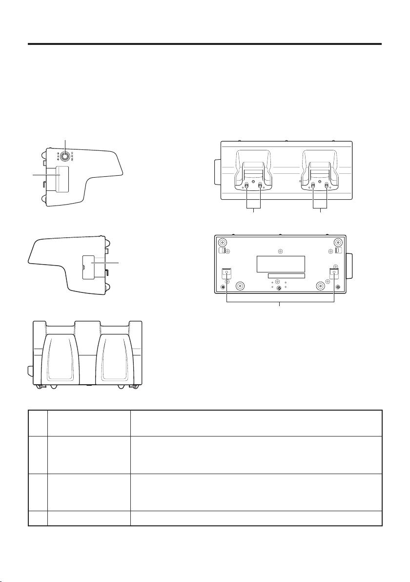
General Guide
Left
1
To p
2
Right
Front
4 4
Bottom
2
3
1 AC Adaptor Jack This is used to supply power by connecting the AC adaptor (sold
separately).
2 Cradle-type Dual
Battery Charger
Use this port to connect multiple Cradle-type Dual Battery
Chargers to each other.
Connection Port
3 Connection
Bracket
The connection bracket attaches here when you connect multiple
Cradle-type Dual Battery Chargers to each other.
Attachment Holes
4 Power Contacts Power is supplied to the Handheld Terminal via these contacts.
E-50
Page 53

Bundled Items
Used when linking two or more Cradle-type Dual Battery Chargers.
Connection
•
bracket (for rear)
Connection
•
bracket (for side)
Connection screws
•
(for rear and side),
2 each
E-51
Page 54

Charging Battery Pack
Use the separately sold AC adaptor (AD-S60160B) for the power supply of the Cradletype Dual Battery Charger.
1. Plug the cord from the AC adaptor into the AC adaptor jack of the Cradle-type Dual
Battery Charger.
2. Plug the AC cord into a wall outlet.
AC Adaptor
AC Adaptor Jack
3. Align the contacts on the bottom of the DT-X100 with the power contacts of the
Cradle-type Dual Battery Charger when inserting the unit.
- Check the charging status with Indicator 1 on the DT-X100.
Status of Indicator 1 on DT-X100
Orange: Charging the battery pack.
Red: Battery pack problem, or standby due to the surrounding temperature being
beyond the specifi ed temperature range (charging resumes when the
temperature reaches the range).
Green: Charging the battery pack is complete.
E-52
Page 55

Connecting Multiple Cradle-type Dual Battery Chargers
You can connect up to three Cradle-type Dual Battery Chargers. Doing so makes
it possible to supply power to all the Cradle-type Dual Battery Chargers using one
dedicated AC adaptor.
1. As shown in the illustrations below, remove the connector covers of the Cradle-type
Dual Battery Chargers you want to connect to each other.
Connector cover
2. Connect the two Cradle-type Dual Battery Chargers as shown below.
Cradle-type Dual Battery
Charger link connector
3. Attach the rear and side connection brackets with the connection screws.
You can repeat the above steps to connect up to 3 Cradle-type Dual Battery Chargers.
* Attach the connection brackets so that the front side faces outwards. (The front side
has protruding ribs.)
Connection brackets
Connection brackets
Rear
Rear
Rib
Rib
Rib
Rib
Side
Side
E-53
Page 56

Specifi cations
1. Charging Specifi cation
Charging Method: Constant current/voltage
Charge Period: Approx. 3 hours (1 standard battery pack)
Approx. 5.5 hours (1 large-capacity battery pack)
2. Power Supply
Power Source: AC adaptor (AD-S60160B)
Consumption Current: 1.25A, 16V DC (1 unit)
3.7A, 16V DC (3 units)
Output to Handheld Terminal: 5V DC 1.6A (max.)
3. AC Adaptor
Model: AD-S60160B
Input: 100V to 240V AC 50/60 Hz 1.5A
Output: 16V DC 3.0A
4. Dimensions and Weight
Dimensions:
Weight: Approximately 500g (17.6oz)
5. Operating Environment
Temperature: Approximately 0°C to 40°C (32°F to 104°F)
Humidity: 30% to 80% RH (non-condensation)
Approximately 189(W)
(7
7
16
⁄
"W × 3
80(D) × 110(H) mm
×
1
5
8
16
"D × 4
⁄
"H)
⁄
E-54
Page 57

Important !
Never short out the power contacts of the Cradle-type Dual Battery Charger.
•
This can damage the Cradle-type Dual Battery Charger.
Allowing the power contacts become wet can cause an electric shock or fi re. In
•
addition, if the contacts become soiled, contact may be impaired resulting in
poor charging. For reasons of safety and maintaining charging battery pack(s)
in optimum condition, clean the power contacts by wiping with a dry cloth or
cotton swab after disconnecting the AC adaptor.
Place the Handheld Terminal in the Cradle-type Dual Battery Charger. Check
•
the Indicator 1 on the terminal to ensure that it has been securely positioned in
the charger. The indicator will light up in orange for correct positioning.
Each unit of the charger comes with one piece each of the side and bottom brackets.
•
After you join two chargers together using these two brackets, one side bracket and
one bottom bracket will be left over. Keep these as spare for use in future.
Before linking multiple Cradle-type Dual Battery Chargers, be sure to
•
disconnect the AC adaptor.
Turn off the power on DT-X100 before placing it in the charger.
•
Place the Cradle-type Dual battery charger on a fl at, level surface and take care
•
when placing the DT-X100 in or removing it from the cradle.
E-55
Page 58

Using the Dual Battery Charger (HA-F32DCHG)
The optionally available Dual Battery Charger (HA-F32DCHG) can be used to
simultaneously charge two battery packs.
General Guide
Left
To p
1
3
Right
Bottom
2
Front
3
4
Bundled Items
Connection Bracket
2 screws
E-56
5
Page 59

1 Charge Indicator
LED
2 AC Adaptor Jack This is used to supply power by connecting the AC adaptor (sold
3 Dual Battery
Charger
Connection Port
4 Connection
Bracket
Attachment Holes
5 Power Contacts Power is supplied to the Handheld Terminal via these contacts.
This LED indicates the charge status of the battery pack(s).
Off: Not charging the battery pack.
Red: Charging the battery pack.
Red Flashing: Battery pack problem
Green Flashing: Standby
Green: Charging the battery pack is complete.
separately).
Use this port to connect multiple Dual Battery Chargers to each
other.
The connection bracket attaches here when you connect multiple
Dual Battery Chargers to each other.
Important!
Allowing the power contacts become wet can cause an electric shock or fi re. In
•
addition, if the contacts become soiled, contact may be impaired resulting in
poor charging. For reasons of safety and maintaining charging battery pack(s)
in optimum condition, clean the power contacts by wiping with a dry cloth or
cotton swab after disconnecting the AC adaptor.
Although the battery may become warm during charging, this is normal and
•
does not indicate a malfunction.
Do not remove the battery pack or disconnect the AC adaptor during charging.
•
Repeated “Mounting and Removing” of battery pack in excess of times may
•
cause the quality deterioration of the battery pack.
Each Dual Battery Charger comes with one connection bracket.
•
Since only one connection bracket is required when you connect two Dual
Battery Chargers, you will always have one left over.
Simply keep the other connection bracket on hand as an extra, in case you ever
need it.
E-57
Page 60
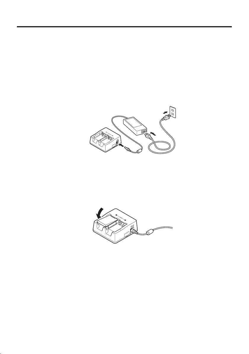
Charging Battery Pack
Use the separately sold AC adaptor (AD-S42120C) for the power supply of the Dual
Battery Charger.
1. Plug the cord from the AC adaptor into the AC adaptor jack of the Dual Battery
Charger.
2. Plug the AC cord into a wall outlet.
3.Taking care that the battery pack is oriented correctly, insert it into the Dual Battery
Charger.
This causes the Charge Indicator LED to light in red, indicating that charging has
started.
Status of Charge Indicator LED
Off: Not charging the battery pack.
Red: Charging the battery pack.
Red Flashing: Battery pack problem
Green: Charging the battery pack is complete.
Green Flashing: Standby due to the surrounding temperature being beyond the
specifi ed temperature range (approximately 0°- 40°C). (charging
resumes when the temperature reaches the range)
E-58
Page 61
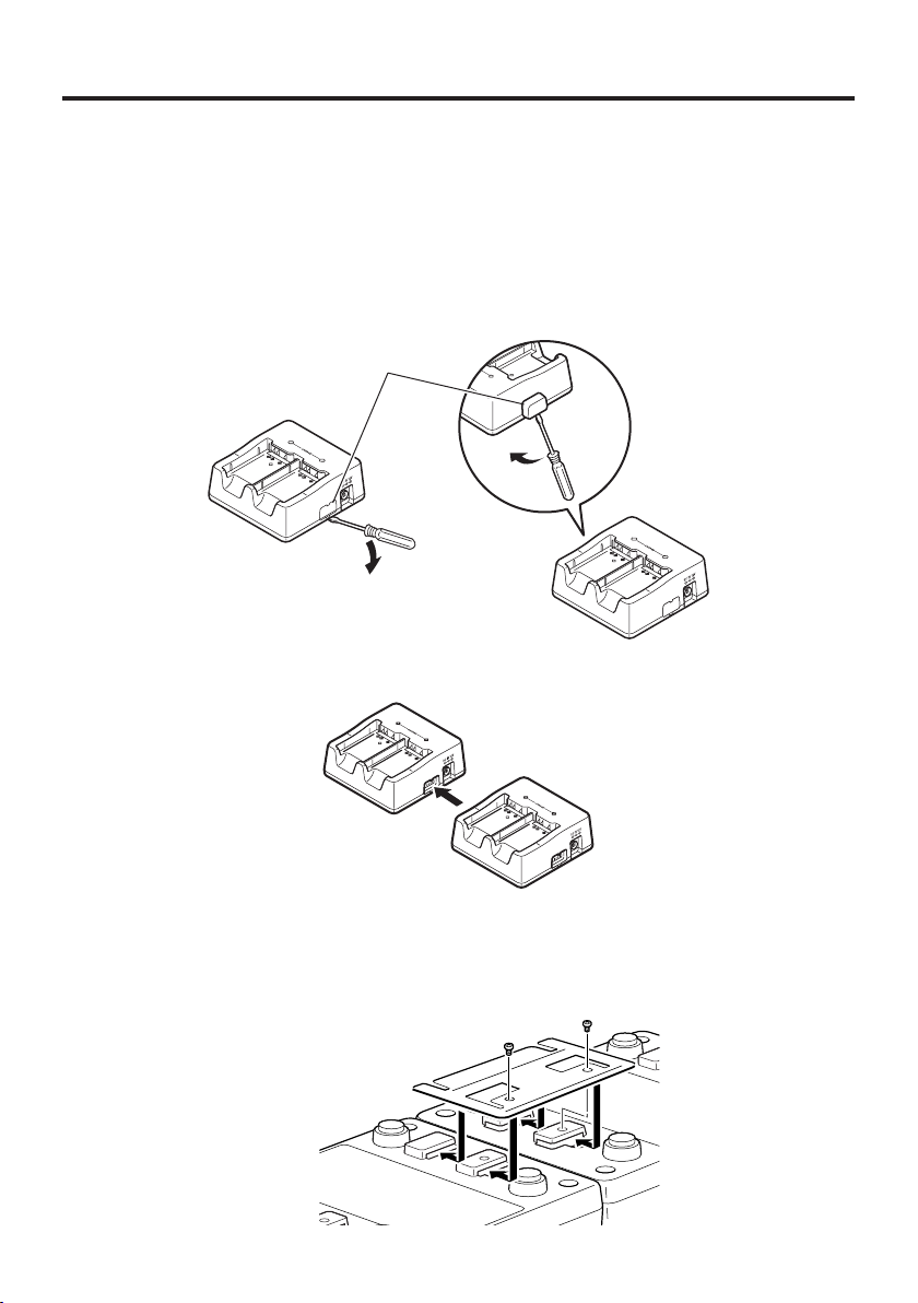
Connecting Multiple Dual Battery Chargers
You can connect up to three Dual Battery Chargers. Doing so makes it possible to
supply power to all the Dual Battery Chargers using one dedicated AC adaptor.
1. As shown in the illustrations below, remove the connector covers of the Dual Battery
Chargers you want to connect to each other.
Connector cover
2. Connect the two Dual Battery Chargers as shown below.
3. Turn over the connected Dual Battery Chargers and attach a connection bracket,
securing it in place with screws.
You can repeat the above steps to connect up to 3 Dual Battery Chargers.
E-59
Page 62

Specifi cations
1. Charging Specifi cation
Charging Method: Constant current/voltage
Charge Period: Approx. 3 hours (1 standard battery pack, normal temperature)
Approx. 5.5 hours (1 large-capacity battery pack, normal
When charging two battery packs:
Approx. 5.5 hours (2 standard battery packs, normal
Approx. 10 hours (2 large-capacity battery packs, normal
2. Power Supply
Power Source: AC adaptor (AD-S42120C)
Consumption Current: 12V DC 3.5A
Output: 4.2V DC 1.1A (max.)
3. AC Adaptor
Model: AD-S42120C
Input: 100V to 240V AC 50/60Hz 1.2A
Output: 12V DC 3.5A
4. Dimensions and Weight
Dimensions:
Approximately 108(W)
Weight: Approximately 152g (5.4oz)
5. Operating Environment
Temperature: Approximately 0°C to 40°C (32°F to 104°F)
Humidity: 30% to 80% RH (non-condensation)
temperature)
temperature)
temperature)
(4
1
4
"W × 4
⁄
104(D) × 45(H) mm
×
1
3
8
4
"D × 1
⁄
"H)
⁄
E-60
Page 63

Using Rechargeable Battery Pack
HA-F20BAT
Your Handheld Terminal supports use of two battery pack types, one at a time, of
different capacity.
You can select the one that best suits your needs in terms of operating time, the type of
options you need to use, etc.
When using the large-capacity battery pack, you need to use the special large-capacity
battery pack cover that comes with the battery pack (HA-F21LBAT).
Important!
Store a battery pack in its special soft case whenever you are not using it.
•
If the battery pack has been left over unused for a long period of time, the
•
capacity remained decreases due to spontaneous discharge or chemical
decomposition by the battery pack itself. If the battery pack fails to hold its
operating duration after it has been fully charged, replace it with a new one. The
battery pack may reach the end of its service life.
Follow the packing instruction promulgated in the IATA DGR 50
•
to transport lithium-ion battery packs.
HA-F21LBAT
th
regulations
E-61
Page 64

Battery Pack Specifi cations
Model: HA-F20BAT
Rated Capacity: 4.07WH (1100mAh)
Rated Voltage: 3.7V
Dimensions:
Approximately 36(W) × 55(D) × 9(H) mm (1
Weight: Approximately 28g (1oz)
Bundled Item: Soft case
Large-capacity Battery Pack Specifi cations
Model: HA-F21LBAT
Rated Capacity: 6.956WH (1880mAh)
Rated Voltage: 3.7V
Dimensions:
Weight: Approximately 46g (1.6oz)
Bundled Item: Soft case
Approximately 36(W) × 55(D) × 14(H) mm (1
7
16
⁄
7
16
"W × 2
⁄
"W × 2
3
16
⁄
3
"D ×
16
⁄
"D ×
9
16
"H)
⁄
3
8
"H)
⁄
E-62
Page 65

Attaching the Hand Belt (HA-F95HB)
To use the Hand Belt (HA-F95HB), attach it to the DT-X100 as follows.
Items Included
Holdfast
•
Hand Belt
•
Attaching the Hand Belt
Attach the Hand Belt as described below.
1. Turn the DT-X100 over.
2. Attach the holdfast on the back of the DT-X100 and secure it using the screws
supplied.
Screw (2pcs)
•
E-63
Page 66

3. Thread the looped cord on the end of the Hand Belt through one of the strap holes at
the bottom of the DT-X100. (You can use either hole.)
Strapholes
4. Feed the belt through the wire loop on the mount, fold it back and secure it with the
hook-loop fastener.
Wireloop
Important!
When inserting the DT-X100 with the Hand Belt attached into the USB Cradle, etc.,
•
check the Power LED on the cradle and the indicator on the DT-X100 to ensure that
the DT-X100 is inserted securely.
The DT-X100 must be inserted correctly to charge and communicate successfully.
E-64
Page 67

CASIO COMPUTER CO., LTD.
6-2, Hon-machi 1-chome
Shibuya-ku, Tokyo 151-8543, Japan
2015 CASIO COMPUTER CO., LTD.
PN430139-003
MO1705-C
 Loading...