

Page 1

Data Collector
Colector de Datos
Datenerfassungsgerät
Collecteur de Données
User’s Guide
Guía del usuario
Benutzerhandbuch
Guide de l’utilisateur
• Congratulations upon your selection of
the CASIO DT-810 Data Collector.
• Be sure to familiarize yourself with the
basic operations described in this
manual before actually trying to
operate the Data Collector.
• Enhorabuena por la selección del
colector de datos DT-810 CASIO.
• Antes de intentar utilizar este colector
de datos, familiarícese con las
operaciones básicas descritas en este
manual.
• Mit dem Datenerfassungsgerät CASIO
DT-810 haben Sie eine gute Wahl
getroffen.
• Bitte machen Sie sich mit den in
diesem Handbuch beschriebenen
Grundfunktionen vertraut, bevor Sie
beginnen, mit dem
Datenerfassungsgerät zu arbeiten.
• Nous vous remercions d‘avoir choisi le
Collecteur de Données Casio DT-810.
• Veuillez vous familiariser avec les
démarches de base, décrites dans le
présent manuel, avant d’essayer
d’utiliser le Collecteur de Données.
Page 2
Safety Precautions
Congratulations upon your selection of this CASIO Product. Be sure to read
the following Safety Precautions before trying to use it for the first time.
Keep this manual in a handy place for future reference.
Markings and Symbols
Danger!
Warning!
Caution!
Marking examples
The following are the meanings of the markings and symbols
used in these Safety Precautions to warn you against the
possibility of personal injury and/or material damage or loss
to you and others. Take a few moments to become familiar
with these markings and symbols so you can avoid future
problems.
This symbol indicates information that, if ignored or
applied incorrectly, creates the danger of death or serious
personal injury.
This symbol indicates information that, if ignored or
applied incorrectly, can create the possibility of death or
serious personal injury.
This symbol indicates information that, if ignored or
applied incorrectly, can create the possibility of personal
injury or material damage.
A triangular shape indicates you should
exercise caution. The symbol shown here
indicates you should take care to avoid
breakage.
A circle indicates something you should not
do. This symbol indicates you should not try to
take something apart.
E-2
A black circle indicates something you must
do. This symbol indicates you should unplug
something.
Page 3
Danger!
■ Alkaline Battery Handling
●Alkaline battery fluid getting into your eyes can create the danger of loss of
sight or other personal injury. If fluid gets into your eyes, do not rub them.
Immediately rinse them with lots of clean tap water, and then consult a
physician immediately.
■ Lithium-ion Battery Pack
The Lithium-ion Battery Pack is available as an option.
●Never allow the battery pack to become wet with either fresh water or salt
water. Water can create the danger of battery pack heat emission, explosion,
and fire.
●Never use or leave the battery pack next to open flame, near a stove, or any
other area exposed to high heat. Doing so creates the danger of battery
pack heat emission, explosion, and fire.
●Never use the battery pack with any device other than this unit. Doing so can
create the danger of battery pack heat emission, explosion, and fire.
●Note that the battery pack’s positive (+) and negative (–) terminals must be
oriented correctly when it is loaded into the charger unit or the Data
Collector. Connecting the battery pack with its terminals reversed creates the
danger of battery pack fluid leakage, heat emission, explosion, and fire.
●Never dispose of the battery pack by incinerating it or otherwise expose it to
heat. Doing so creates the danger of battery pack heat emission, explosion,
and fire.
●Never allow the positive (+) and negative (–) terminals of the battery pack to
become connected (shorted) by metal. Doing so creates the danger of
battery pack heat emission, explosion, and fire.
●Never transport or store the battery pack together with a necklace, hair pins
or other metal objects. Doing so can short battery pack terminals, creating
the danger of battery pack heat emission, explosion, and fire. Be sure to
place the battery pack in its case whenever transporting or storing it.
●Never throw the battery pack or otherwise subject it to strong impact. Doing
so creates the danger of battery pack heat emission, explosion, and fire.
●Never pierce the battery pack with nails, hit it with a hammer, or step on it.
Doing so can create the danger of battery pack heat emission, explosion,
and fire.
●Never try to take apart the battery pack or modify it in any way. Doing so
creates the danger of battery pack heat emission, explosion, and fire.
●Use only the specified charger unit to charge the battery pack. Use of
another type of charger unit creates the danger of battery pack heat
emission, explosion, and fire.
E-3
Page 4
Warning!
■ Disassembly and Modification
●Never try to disassemble or modify the unit in any way. High voltage inside
creates the danger of electrical shock.
■ Interior Parts and Components
●Never touch interior high-voltage parts or components. Doing so creates the
danger of electrical shock.
■ Abnormal Conditions
●Should the unit become hot or start to emit smoke or a strange odor,
immediately turn off power and contact your original dealer or authorized
CASIO service provider. Continued use creates the danger of fire and
electrical shock.
■ Foreign Objects
●Should any foreign matter ever get into the unit, immediately turn off power
and contact your original dealer or an authorized CASIO service provider.
Continued use creates the danger of fire and electrical shock.
■ Dropping and Damage
●Should you drop the unit and damage it, immediately turn off power and
contact your original dealer or an authorized CASIO service provider.
Continued use creates the danger of fire and electrical shock.
■ Moisture
●Keep the unit away from vases, planters, cups, glasses and other containers
■ Laser Beam
●Never look directly into the laser beam. Doing so can cause serious eye
E-4
of liquid. Also keep it away from metal. Water and metal getting into the unit
creates the danger of fire and electrical shock.
damage.
Page 5
Warning!
■ Alkaline Battery and Backup Battery Handling
●Do not throw batteries into fire, or heat, take apart or modify them. Doing so
can damage the insulation or safety valves, and can create the danger of
battery leakage, heat emission, and rupture.
●Do not use the battery with its positive (+) and negative (–) terminals
reversed. Doing so can cause abnormal reactions by charging and shorting,
and can create the danger of battery leakage, heat emission, and rupture.
Do not connect the positive (+) and negative (–) terminals of the battery with
●
wire, or transport or store the battery with a necklace, hair pins or other metal
objects. Doing so can short the battery and cause excessive current to flow,
and can create the danger of battery leakage, heat emission, and rupture.
●Do not use new batteries together with already used batteries or different
types of batteries. Differences in the battery characteristics can create the
danger of battery leakage, heat emission, and rupture.
●Alkaline batteries are not made for recharging. Recharging alkaline batteries
damages the insulation and its internal structure, and can create the danger
of battery leakage, heat emission, and rupture.
●Do not peel off or scratch the outer label on the battery. Doing so can short
the battery, and can create the danger of battery leakage, heat emission,
and rupture.
●Do not drop or throw batteries, or subject them to strong impact. Doing so
can create the danger of battery leakage, heat emission, and rupture.
●Do not deform batteries. Doing so can damage the insulation or safety
valves, and can create the danger of battery leakage, heat emission, and
rupture.
●Never charge the backup battery. Doing so can cause the battery fluid to boil
or internal pressure to rise due to the generation of gas. This can create the
danger of battery leakage, heat emission, rupture, and fire.
Never directly solder the backup battery. Heat can damage the insulation, and
●
can create the danger of battery leakage, heat emission, rupture, and fire.
●Keep batteries out of the reach of small children. Should small children
swallow a battery, consult a physician immediately.
●If you lick alkaline fluid from the battery, immediately rinse with clean tap
water, and consult a physician immediately.
●If alkaline fluid from the battery accidentally get onto clothing or your skin,
immediate rinse it off with lots of clean tap water. Prolonged contact with
battery fluid can cause skin irritation.
●If the backup battery starts to leak or emits a strange odor, immediately
move it away from any nearby flame. Leaking battery fluid is combustible.
●When storing and disposing of backup batteries, insulate the terminals with
insulating tape. Mixing batteries together or with other metallic objects shorts
the battery terminals, and can create the danger of battery leakage, heat
emission, rupture, and fire.
E-5
Page 6
Warning!
■ Lithium-ion Battery Pack
The Lithium-ion Battery Pack is available as an option.
●Never place the battery pack into a microwave oven or any other highvoltage device. Doing so creates the danger of battery pack heat emission,
explosion, and fire.
●Should the battery pack emit a strange odor or heat, change color or shape,
or exhibit any other abnormal behavior, immediately stop using it. Continued
use creates the danger of battery pack heat emission, explosion, and fire.
●If the battery pack does not achieve full charge after the normal charging
time has passed, stop charging. Continued charging creates the danger of
battery pack heat emission, explosion, and fire.
●Should the battery back starts to leak or emit a strange odor, immediately
move it away from any nearby flame. Leaking battery fluid is combustible,
and exposure to flame creates the danger of explosion and fire.
●Should fluid from the battery pack accidentally get into your eyes, do not rub
them. Immediately rinse your eyes with clean tap water and then consult a
physician immediately.
■ Optional Optical Communication Unit and Charger Unit
●Power the Optical Communication Unit and charger unit only with a power
outlet whose voltage matches that marked on the Optical Communication
Unit and charger unit. Do not plug the Optical Communication Unit and
charger unit into an extension shared by other appliances. Doing so creates
the danger of fire and electrical shock.
●Avoid conditions that can cause damage or breaks in the power cord. Do not
place heavy objects on the power cord and keep it away from sources of
heat. Any of these conditions can damage the power cord, creating the
danger of fire and electrical shock.
●Never modify, sharply bend, twist, or pull on the power cord. Doing so
creates the danger of fire and electrical shock.
E-6
●Use only the AC adaptor model and charger specified in this manual. When
using the Optical Communication Unit, always use the AC adapter suplied
with the Optical Communication Unit. Use of another AC adaptor model or
charger creates the danger of fire and electrical shock.
●Should the power cord ever become severely damaged (to the point that
wires are exposed or broken), contact your original dealer or CASIO service
provider about repair or replacement. Use of a damaged electrical cord
creates the danger of fire and electrical shock.
Page 7
Warning!
■ Make back-up copies of all important data
●Note that CASIO Computer Co., Ltd. shall not be held liable to you or any
third party for any damages or loss caused by deletion or corruption of data
due to use of this, malfunction or repair of this unit or its peripherals, or due
to batteries going dead.
●This unit employs electronic memory to store data, which means that
memory contents can be corrupted or deleted if power is interrupted due to
batteries going dead or incorrect battery replacement procedures. Data
cannot be recovered once it is lost or corrupted. Be sure to make back-up
copies of all important data. One way to do this is to use the optional Optical
Communication Unit to transfer data to a computer.
Caution!
■ Foreign Objects
●Take care to ensure that metal or combustible objects are not inserted into
the openings of the unit. Such objects create the danger of fire and electrical
shock.
■ Location
●Do not locate the unit on a surface that is unstable or uneven. Doing so
creates the danger of the unit falling or tipping over, which can cause
personal injury.
●Do not locate the unit in an area subjected to large amounts of humidity or
dust. Doing so creates the danger of fire and electrical shock.
●Do not leave the unit for long periods in a car parked in direct sunlight.
■ Heavy Objects
●Never place heavy objects on top of the unit. Doing so creates the danger of
loss of balance and the object falling, which can cause personal injury.
■ LCD Screen
●
Never apply strong pressure to the screen or subject it to strong impact. Doing
so can crack the LCD panel glass and create the danger of personal injury.
●Should the LCD panel glass ever break, never touch the liquid inside. Doing
so can cause skin irritation and inflammation.
• Should liquid from the LCD panel accidentally get into your mouth,
immediately wash your mouth with water and then consult a physician.
• Should liquid from the LCD panel accidentally get into your eyes or onto
your skin, immediately rinse for at least 15 minutes with clean tap water
and then consult a physician.
E-7
Page 8
Caution!
■ Alkaline Battery and Backup Battery Handling
●Do not leave batteries in locations subject to strong direct sunlight or in high
temperature locations such as in a car. Doing so can create the danger of
battery leakage, heat emission, and rupture.
●Do not allow batteries to get wet with water. Doing so can create the danger
of heat emission.
●Remove completely used batteries from the equipment immediately. Leaving
used batteries for a long time still connected to the equipment can cause gas
to be generated from the battery. This can create the danger of battery
leakage, heat emission, and rupture, or damage the equipment.
●If batteries are to be used in a completely sealed structure, follow the
instructions in the equipment’s Instruction Manual.
●If the equipment is not to be used for a long time, back up important data
and remove the batteries. Leaving batteries for a long time in the equipment
can cause gas to be generated from the battery. This can create the danger
of battery leakage, heat emission, and rupture, or damage the equipment.
●When storing and disposing of alkaline batteries, insulate the terminals with
insulating tape. Mixing batteries together with other batteries or metallic
objects can create the danger of battery leakage, heat emission, and
rupture.
●Battery specifications or performance sometimes is not fully achieved
depending on how they are used or the equipment they are used on.
Correctly use batteries in a way suited to the application in accordance with
the equipment’s Instruction Manual or precautions.
●Avoid storing batteries in the direct sunlight or in high temperature and
humidity locations. Doing so can create the danger of battery leakage, impair
battery performance or shorten the service life of the battery.
●Used batteries may be disposed off as general unburnable rubbish.
However, dispose of used batteries in accordance with any local bylaws and
regulations.
●Use only battery types that are specified for this unit.
●The positive (+) and negative (–) terminals sometimes contact the metallic
sections of some equipment near the battery insertion area. Insert batteries
into equipment taking care not to short the terminals.
E-8
Page 9
Caution!
■ Lithium-ion Battery Pack
The Lithium-ion Battery Pack is available as an option.
●Never leave the battery pack in an area exposed to direct sunlight, in a car
parked in direct sunlight, or any other very hot area. Doing so creates the
danger of heat emission and fire, as well as deterioration of battery pack
performance and shortening of its service life.
●Do not use the rechargeable battery pack in areas where static electricity is
being generated. Doing so creates the danger of battery pack heat emission,
explosion, and fire.
●Temperature ranges for battery pack use, charging, and storage are
specified below. Temperatures outside these ranges create the danger of
deterioration of battery pack performance and shortening of its service life,
as well as fluid leakage and heat generation.
Operating Temperature: –10°C to 50°C
Charging Temperature: 0°C to 40°C
Storage Temperature: –20°C to 60°C
●Should fluid from the battery pack accidentally get onto clothing or your skin,
immediately rinse it off with clean tap water. Prolonged contact with battery
pack fluid can cause skin irritation.
●Keep the battery pack out of the reach of small children. Do not let small
children remove the battery pack from the charger unit or the unit it is
powering.
■ Optional Optical Communication Unit and Charger Unit
●Keep the power cord away from stoves and other sources of extreme heat.
Heat can melt the insulation of the power cord and create the danger of fire
and electrical shock.
●Never pull on the power cord when unplugging it. Doing so can damage the
cord and create the danger of personal injury, fire and electrical shock.
Always hold onto the plug when unplugging it from the wall outlet.
●Never touch the plug while your hands are wet. Doing so can create the
danger of electrical shock.
●Be sure to unplug the power cord from the wall outlet before moving the
Optical Communication Unit and Charger Unit. Failure to do so can result in
damage to the power cord caused by pulling it, which creates the danger of
fire and electrical shock.
●Be sure to unplug the power cord from the wall outlet before cleaning the
Optical Communication Unit and Charger Unit.
●Be sure to turn the power OFF and unplug the power cord after use.
●Unplug the power cord from the wall outlet whenever leaving the Optical
Communication Unit and Charger Unit unattended for long periods.
E-9
Page 10

• The contents of this manual are subject to change without notice.
• The term “Data Collector” as used in this User's Guide refers to the CASIO DT-810 Data
Collector unless otherwise noted.
• CASIO COMPUTER CO., LTD. assumes no responsibility for any loss or claims by third
parties which may arise from the use of this manual.
• This manual does not cover programming or the uploading of data. See the separate
manual for details of these procedures.
Contents
Safety Precautions ............................................... E-2
Unpacking ........................................................... E-12
Introduction......................................................... E-13
Handling Precautions...........................................................E-13
Data Collector Handling Precautions ............... E-13
DT-810 System Diagram..................................... E-14
General Guide ..................................................... E-15
Power Supply ...................................................... E-16
Loading Alkaline Batteries ................................................... E-17
Installing the Lithium-ion Battery Pack.................................E-18
Installing the Back-up Battery ..............................................E-19
E-10
Attaching the Wrist Strap................................... E-22
Keys and Their Functions.................................. E-23
Stroke Key Functions...........................................................E-23
Touch Panel Keys ................................................................E-24
Before Using the Data Collector for the First Time..
Aligning the Touch Panel Position ....................................... E-25
E-25
Using the Bar Code Reader ............................... E-27
Performing a Bar Code Read Operation..............................E-27
Scan Position....................................................................... E-28
Page 11

Data Communication.......................................... E-29
DT-810-DT-810/800 Data Communication .......................... E-29
DT-810-Computer Communication...................................... E-29
Specifications ..................................................... E-30
DT-823LI Lithium-ion Battery Pack Specifications...............E-31
Using the Optional Optical
Communication Unit ....................................... E-32
General Guide .....................................................................E-32
Setting up the Optical Communication Unit and
connect the Data Collector.............................................. E-34
Charging the Battery Pack................................................... E-35
Setting the Optical Communication Unit ..............................E-36
Connecting Two or More Optical Communication Units ......E-38
DIP Switch Settings ............................................................. E-39
DT-860IOE Optical Communication Unit Specifications...... E-40
Using the High-Speed Charger Unit.................. E-41
General Guide .....................................................................E-41
Charging a Battery Pack...................................................... E-41
DT-820CHGE High-Speed Charger Unit Specifications...... E-43
CASIO ELECTRONICS CO., LTD.
Unit 6, 1000 North Circular Road
London NW2 7JD, U.K.
E-11
Page 12
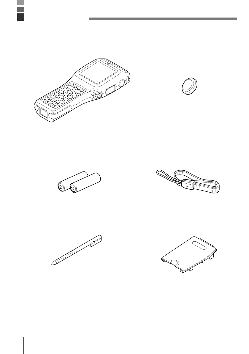
Unpacking
When unpacking the Data Collector, check carefully to make sure that all of the items shown
below are included. If anything is missing or damaged, contact your original dealer or your
nearest CASIO Service Provider.
• Data Collector • Back-up battery (lithium)
M60E/M70E
• Main batteries • Wrist Strap
(Two AA (LR6)-size alkaline batteries)
E-12
• Touch panel stylus • Battery compartment cover for
lithium-ion battery pack
Page 13

Introduction
Make sure you carefully read the following information to ensure that your Data Collector is
able to perform at the level for which it is designed.
Handling Precautions
• Never try to take the unit apart or modify it in any way.
• Avoid leaving the Data Collector in direct sunlight, near heaters, or in any other area where
it might be subjected to intense heat for long periods. Also avoid areas subjected to high
humidity and large amounts of dust. Do not leave the Data Collector in a closed motor
vehicle.
• Do not throw or drop the Data Collector or otherwise subject it to strong impact, which can
damage the LCD screen, interrupt program execution, corrupt memory contents, or
otherwise interfere with proper operation.
• Use only your finger or a blunt object to operate the stroke keys, and your fingers or the
supplied stylus to operate the touch panel. Use of a sharp pointed object can damage
stroke keys and the touch panel, and cause shorting of internal circuitry.
• Use a soft, dry cloth when cleaning the Data Collector. Do not wipe with a wet cloth. Do not
use benzine, thinner, or other volatile chemicals, which can result in deformation and
deterioration of the materials used in the keys and case.
• Never place any objects on top of the Data Collector.
• Do not lay the Data Collector down with its key panel downwards. Doing so runs the risk of
accidental key operation, which can cause malfunction.
Data Collector Handling Precautions
• Never remove the main batteries while Data Collector power is turned on. Doing so will
cause all data in memory to be lost.
• Sudden temperature changes can cause condensation to form on the Data Collector’s
case. Operating the Data Collector while condensation is present can interfere with proper
operation. Take care to avoid conditions that cause the formation of condensation. If
condensation does form, wait until it dries completely before using the Data Collector.
E-13
Page 14
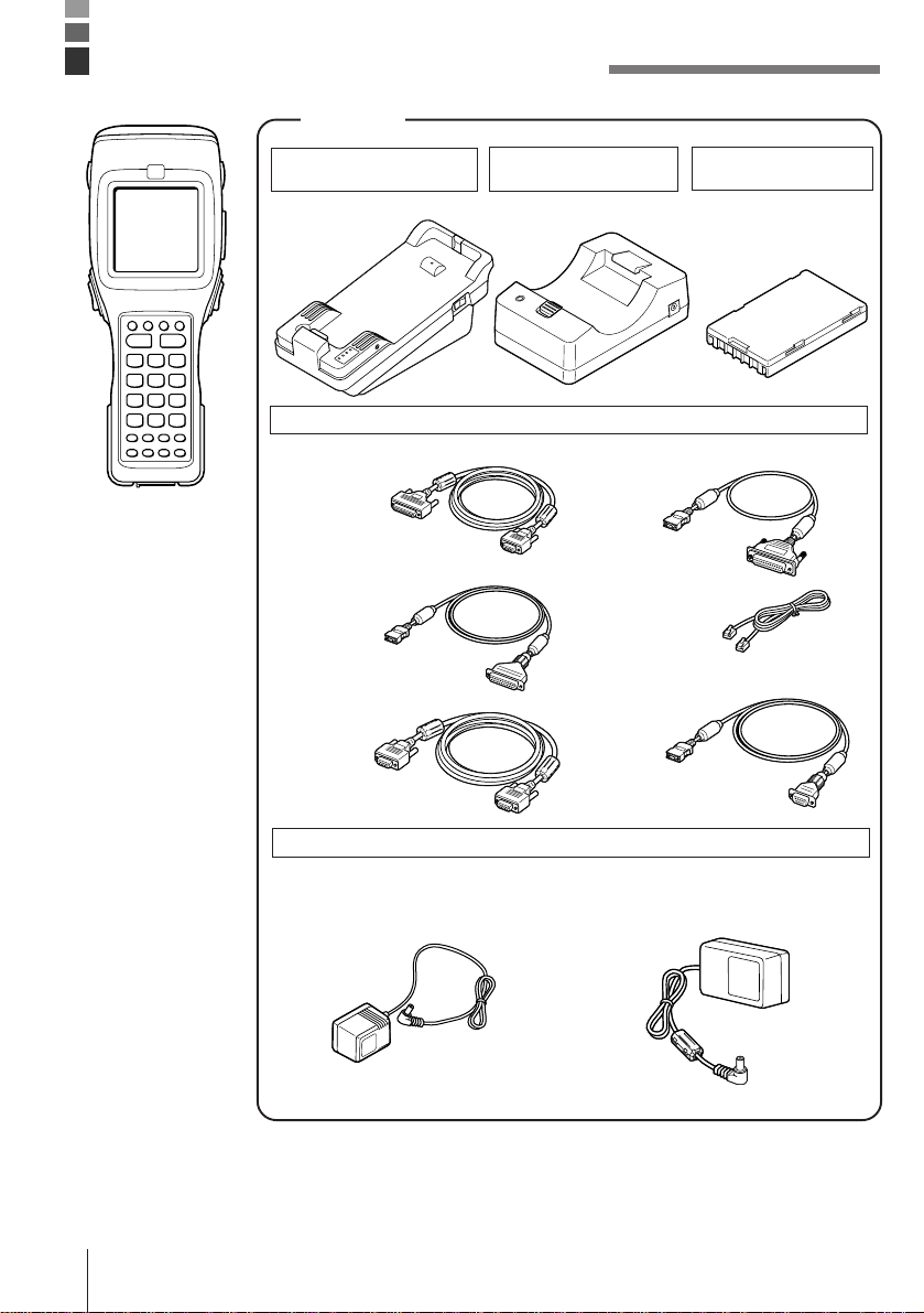
DT-810 System Diagram
Options
Optical
Communication Unit
DT-860IOE
High-speed
Charger Unit
DT-820CHGE
Cables
Lithium-Ion
Battery Pack
DT-823LI
M60E/M70E
DT-881RSC
DT-882RSC
DT-883RSC
DT-884RSC
DT-885RSC
DT-887AX
AC Adaptor
For High-Speed Charger Unit
DT-9020ADP-G DT-9020ADP-U
SB-703
DT-888RSC
DT-889AX
For Optical Communication Unit
DT-825ADP-G DT-825ADP-U
E-14
Page 15
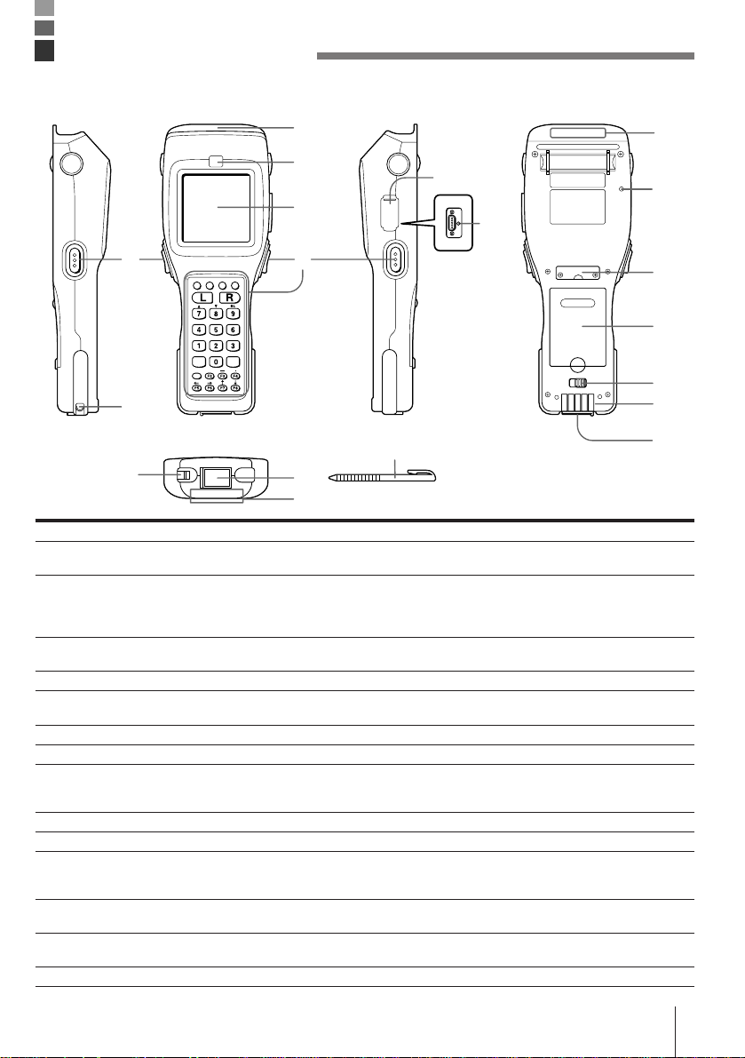
General Guide
• Left side
• Front
• Right side
1
• Back
8
2
5
9
3
6
4
4
10
11
12
7
7
• Bottom
15
14
13
14
13
1 Reader port Emits a laser for bar code reading.
2 Read indicator Indicates the status of the read operation: green for a successful read, red
3 LCD screen and touch panel Displays various data when a program is being run (LCD screen). Areas on
4 Stroke keys A total of 28 keys are provided to turn power on and off, to trigger bar code
5 RS-232C connector (inside cap) Allows connection of other devices for system expansion.
6 Reset button (inside cap) Use a paper clip or other thin object to press the RESET button located
7 Wrist strap hook Hook for installing the wrist strap.
8 Laser warning label Class 1 laser warning label.
9 Speaker Outputs operation confirmation tones. Take care to avoid blocking the
10 Back-up battery compartment Holds memory backup lithium battery.
11 Main battery compartment Holds main batteries.
12 Main battery compartment lock Locks main battery compartment cover in place. Data Collector power does
13 Charger/AC terminal This terminal receives power when the Data Collector is attached to an
14 Infrared port This port is for contact-less infrared data communication with another
15 Touch panel stylus Use this stylus for touch panel key input.
when the read is no good.
the screen can touched with the finger or supplied stylus to perform various
key operations (touch panel). Pressing a key inputs the alpha character or
punctuation marked on it.
reading, and for other operations.
inside the hole.
speaker holes and reducing output sound volume. Never insert any thin,
pointed object into the speaker holes. Doing so can cause malfunction.
not turn on if the battery compartment cover lock is not in the LOCK
position.
optional Optical Communication Unit.
DT-810/DT-800 unit or an optional Optical Communication Unit.
E-15
Page 16

Power Supply
The Data Collector has both a main power supply (two AA (LR6)-size alkaline batteries or a
lithium-ion battery pack) and a backup power supply (lithium battery). In this manual, the
words “main batteries” refer to both alkaline batteries and the lithium-ion battery pack.
Low main battery power is indicated when the low voltage message appears on the LCD
screen. Replace the main batteries or charge the battery pack as soon as possible after the
low voltage message appears.
Important! • Never remove both the main batteries and backup battery at the same
time. Doing so causes all programs and data in Data Collector memory
to be lost.
• Never remove the main batteries from the Data Collector while power it
turned on. Doing so can cause data stored in memory to be deleted. Be
sure to turn the Data Collector off before removing batteries.
• Use only AA (LR6)-size alkaline batteries or the specified lithium-ion
battery pack specified for the DT-810.
• The lithium-ion battery pack discharges naturally during the time it
takes for it to get from the factory to you. Make sure to charge the
battery pack before using it for the first time.
• Never allow the terminals of the lithium-ion battery to become shorted.
Doing so creates the danger of malfunction. Be sure to keep the battery
pack in its special case when transporting or storing it.
• Repeat charging of the lithium-ion battery pack gradually shortens its
ability to recharge. If you find that a fully charged battery pack provides
only little operation time, it probably means you need a new battery
pack.
• Whenever you do not plan to use the Data Collector for a long time,
load two new alkaline batteries or a fully charged battery pack into the
Data Collector to protect against power failure during non-use. Also,
load new batteries or a fully charged battery pack before using the Data
Collector after a long period of non-use.
E-16
Page 17
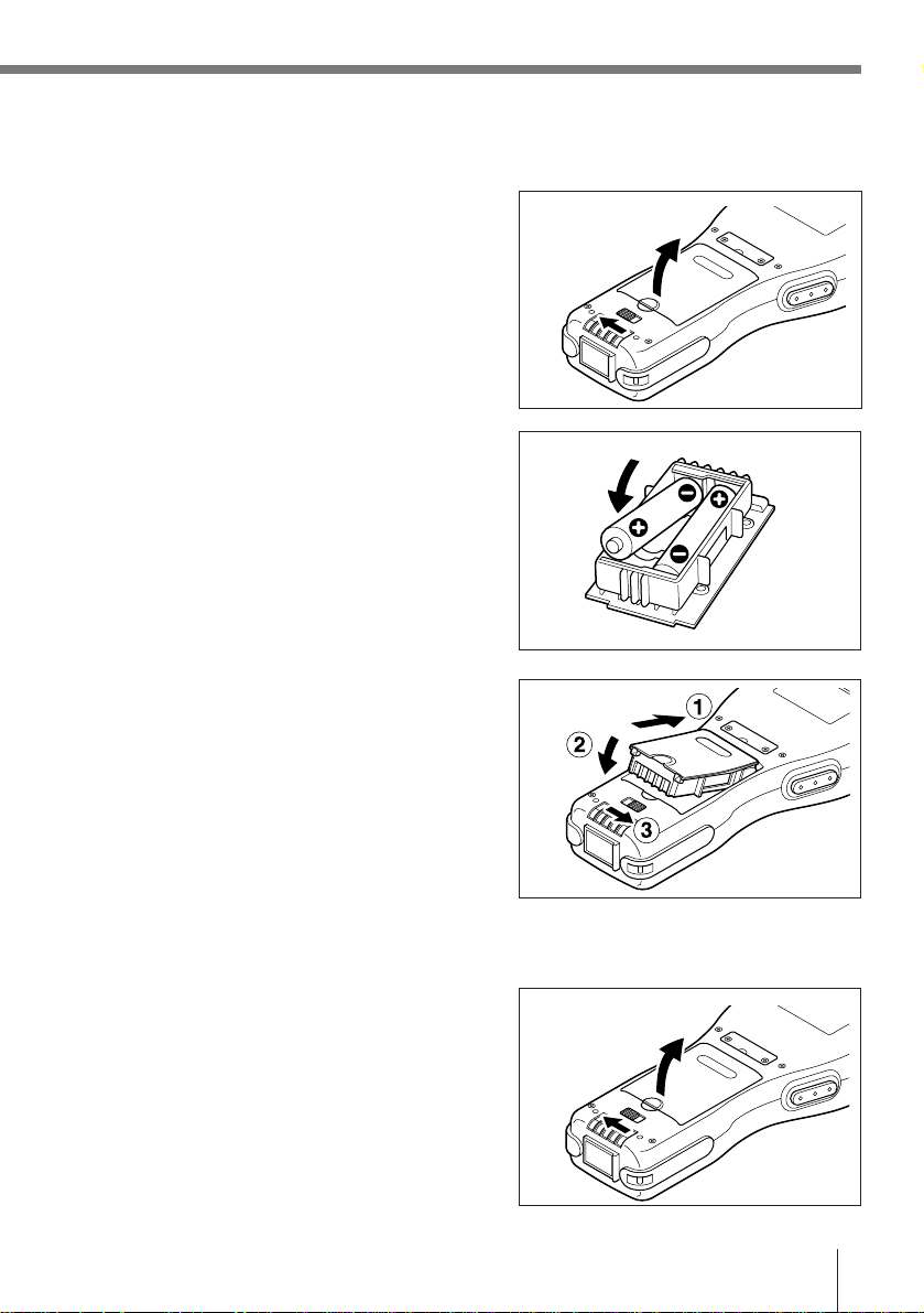
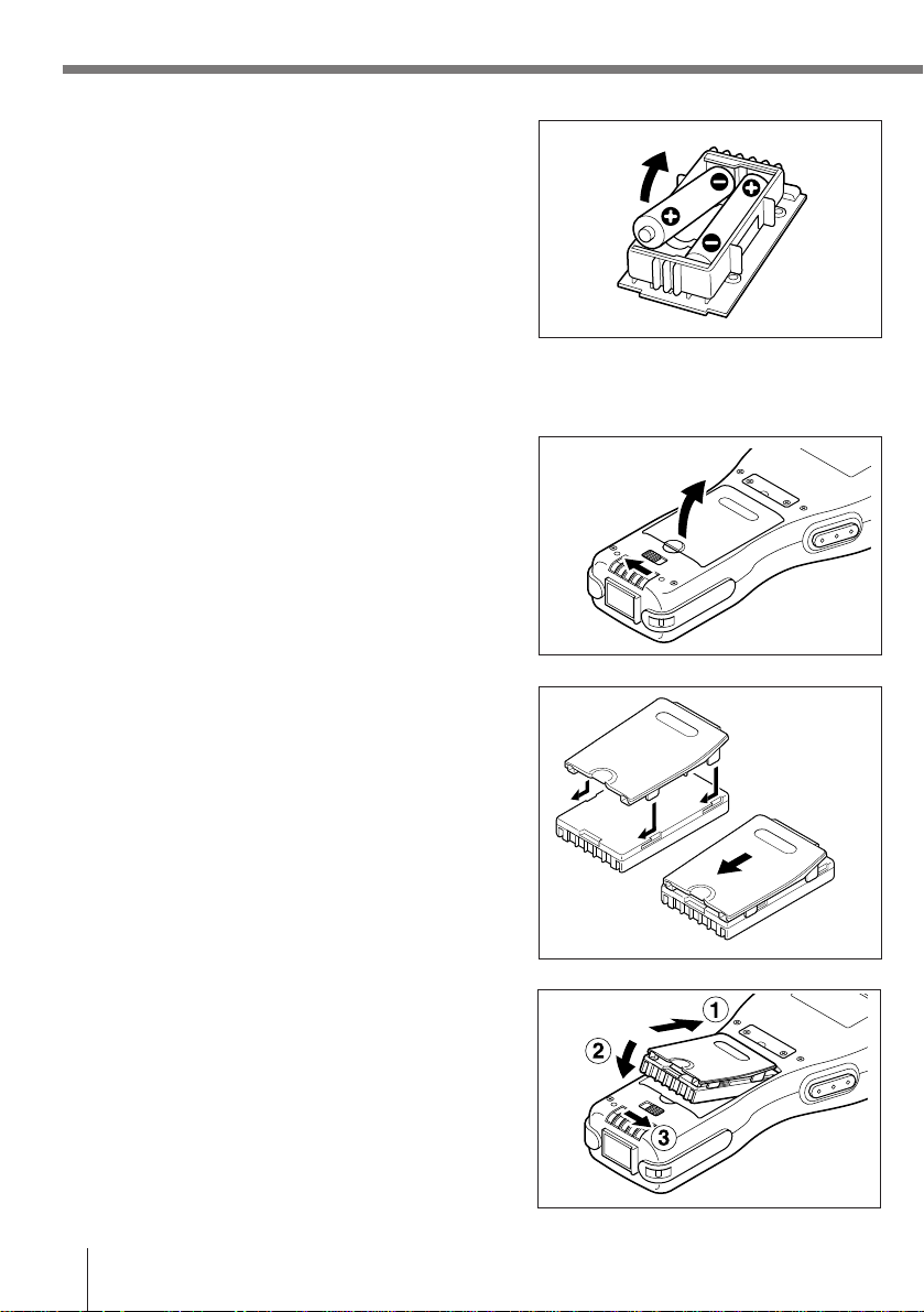
Loading Alkaline Batteries
1 Slide the main battery compartment cover lock
to the FREE position and remove the cover.
2 Install two new AA (LR6)-size alkaline batteries
onto the battery compartment cover, making
sure their positive (+) and negative (–) ends
are facing correctly.
3 Attach the battery compartment cover to the
Data Collector and slide the main battery
compartment cover lock to the LOCK position.
To remove alkaline batteries
1 Slide the main battery compartment cover lock
to the FREE position and remove the cover.
E-17
Page 18
Power Supply
2 Remove the alkaline batteries from the battery
compartment cover.
Installing the Lithium-ion Battery Pack
1 Slide the main battery compartment cover lock
to the FREE position and remove the cover.
2 Taking care to correctly orient the terminals of
the battery pack, align the tab on the back of
the supplied lithium-ion battery pack battery
compartment cover with the groove of the
battery pack, and slide the battery pack onto
the cover.
3 Attach the battery compartment cover to the
Data Collector and slide the main battery
compartment cover lock to the LOCK position.
E-18
Page 19

To remove the lithium-ion battery pack
1 Slide the main battery compartment cover lock
to the FREE position and remove the cover.
2 Slide the lithium-ion battery pack from the
battery compartment cover.
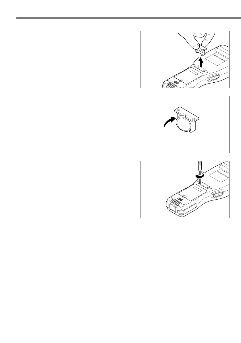
Installing the Back-up Battery
1 Use a screwdriver to rotate the screw that
secures the backup battery holder in place
counterclockwise to loosen it.
2 Insert a screwdriver or some flat object into the
back of the backup battery holder and pull out
it.
E-19
Page 20
Power Supply
3 Pull out the backup battery holder.
4 Wipe off a CR2032 lithium battery with a dry
cloth, and load it into the backup battery case
so its plus (+) side is facing towards the holder
(so you can’t see it).
5 Load the battery holder into the Data Collector
and tighten the screw.
Insert from the hook side
To replace the Back-up Battery
Replace the backup battery as soon as possible after the low voltage message appears on the
display. Always make sure that power is turned off when replacing the backup battery, and use
only a CR2032 lithium battery.
Important! • Removing the lithium backup battery while the main batteries are
removed or while main battery power is low can cause data stored in
memory to become corrupted.
• Always double check to make sure the positive (+) side of the backup
battery is facing correctly.
E-20
Page 21

1 Use a screwdriver to rotate the screw that
secures the backup battery holder in place
counterclockwise to loosen it.
2 Insert a screwdriver or some flat object into the
back of the backup battery holder and pull out
it.
3 Pull out the backup battery holder.
4 Remove the old backup battery. Wipe off a
new CR2032 lithium battery with a dry cloth,
and load it into the backup battery case so its
plus (+) side is facing towards the holder (so
you can’t see it).
5 Load the battery holder into the Data Collector
and tighten the screw.
E-21
Page 22

Attaching the Wrist Strap
The wrist strap protects the Data Collector against being damaged by dropping during
transport.
To attach the wrist strap
1 Pass the wrist strap through the metal wrist
strap bar on the bottom of the data collector.
2 Double the strap back through its own loop,
and pull it tight.
Important! • Never swing the Data Collector around by its wrist strap.
E-22
Page 23

Keys and Their Functions
Operations are controlled by 28 stroke keys and touch panel keys.
Stroke Key Functions
1 Trigger key
Triggers a bar code read operation. Any other function
can also be assigned to this key.
2 Control keys
FNC key: Switches between the Function Mode and
Normal Mode.
BS key: Backspaces and deletes one character.
LOCK key: Enables and disables user-defined keys.
3 Multi-function (L/R) keys
Keys that can be assigned any function.
1
2
3
4
5
4 10-key pad
1
6
7
8
The function of these keys depends on whether the Data
Collector is in the Normal Mode or Function Mode.
Normal Mode: Numeric input
Function Mode:
0 to 6: Executes function assigned to each key.
7: Increases display contrast.
8: Decreases display contrast.
9: Turns display backlight on and off.
5 Clear key Clears previous key input.
6 Power key Turns power on and off.
7 Enter key Registers input.
8 Function keys
Keys that can be assigned any function except for the
trigger key function. The following are the initial
functions assigned to these keys.
F1 (Alpha): Displays a keypad of alpha characters and
punctuation (during key input standby
only).
F2 (SP): Inputs a space.
F3 (−): Inputs a minus (−) sign.
F4 (.): Inputs a period.
F5 (←): Moves the cursor left.
F6 (→): Moves the cursor right.
F7 (↑): Moves the cursor up.
F8 (↓): Moves the cursor down.
E-23
Page 24

Keys and Their Functions
Touch Panel Keys
The touch panel on the LCD screen of the Data Collector can be operated with your finger or
the supplied stylus to input data. Use of the stylus is recommended whenever you have
problems operating the touch panel with your finger.
Inputting alpha characters and punctuation
Pressing the F1 (Alpha) key while the Data Collector is
standing by for input enters the Alpha Mode and
displays an alpha character touch panel screen.
Switching Between Alpha Mode Touch Panel Screens
Pressing the Multi-function (L/R) keys while in the Alpha Mode changes the touch panel
screen as shown below.
R keyL key
Touch Panel Alignment
Perform touch panel alignment whenever you find that the position of the touch panel keys is
not aligned with the area of the LCD screen that must be pressed to perform the function of
the keys.
Important! • Should a message appear alerting you to a touch panel abnormality,
take the Data Collector to your original dealer or an authorized CASIO
service provider for maintenance.
E-24
Page 25

Before Using the Data Collector for the First Time
Be sure to perform the reset operation described below before using the Data Collector for
the first time after you purchase it.
Make sure Data Collector power is turned off.
↓
Use a paper clip or some other thin object to press the RESET button.
↓
Perform touch panel alignment.
↓
↓
The system menu starts up.
Important! • The above procedure needs to be performed only before you use the
Data Collector for the first time after purchasing it, or after memory
contents are deleted due to main batteries and the backup battery
going dead or being removed at the same time. If the RESET button is
pressed accidently, you must complete the other steps of the above
procedure to reset the Data Collector.
Perform a RAM drive check. If the drive is not
formatted, display the check screen and format it.
Aligning the Touch Panel Position
Always correctly align the touch panel position.
Failure to do this may cause problems. For instance ...
— the display might not match the position you touched
— the display might not show the same characters you entered
So set correctly and promptly realign the touch panel if position errors occur.
HOW TO ALIGN THE TOUCH PANEL
1 Finish any on-going job and turn off the
power.
2 Display the SYSTEM MENU as follows.
Press
to start up the SYSTEM MENU.
PW
while holding down
FNC
and
3 Press to select the touch panel
CALIBRATION menu.
SYSTEM MENU
1 : EXECUTE AP
2 : SET MODE
3 : DATE / TIME
4 : TRANSMIT
5 : CALIBRATION
6 : VERSION
E-25
Page 26

Before Using the Data Collector for the First Time
4 Make the touch panel alignment.
Using the stylus (pen) supplied with the unit,
touch the centers of the 4 plus (+) marks in
the order shown by the arrows.
5 Press on the menu to end the touch panel
alignment.
< CALIBRATION >
Touch the center
of mark by the
pen which the
arrow points.
< CALIBRATION >
Calibration
Finished !
1 : Retry 2 : End
6 Press to quit the SYSTEM MENU.
E-26
SYSTEM MENU
1 : EXECUTE AP
2 : SET MODE
3 : DATE / TIME
4 : TRANSMIT
5 : CALIBRATION
6 : VERSION
Page 27
Using the Bar Code Reader
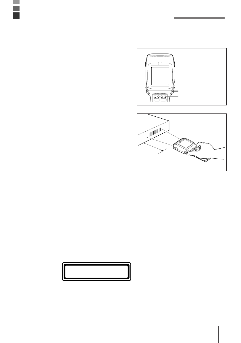
Performing a Bar Code Read Operation
1 Turn on the Data Collector, position the reader
port close to the bar code you want to read,
and then press the trigger key.
Reader port
Read indicator
Trigger key
Power key
2 The reader port emits a laser to read the bar
code. The read indicator lights green when the
read is successful.
Maximum distance:
Approximately 38 cm
(Normal Mode)
Important! • If you have problems with the read operation, change the angle
between the label and Data Collector, or move closer and then try
again.
• If the bar code is larger than the diameter of the Data Collector’s reader
port, try moving the Data Collector a bit farther away from the bar code.
• The Data Collector should be able to read a bar code from the
maximum distance of 38 centimeters under the following conditions.
Ambient Light: 500 lux (fluorescent)
PCS: 0.9 min.
Minimum Bar Width: 1.2 mm
ITF (extended version)
CLASS 1
LASER PRODUCT
EXPLANATORY LABEL
• Wavelength: 670 nm
Maximum output: 1.0 mW
• CAUTION
Use of controls or adjustments or
performance of procedures other
than those specified herein may
result in hazardous radiation
exposure.
E-27
Page 28

Using the Bar Code Reader
Scan Position
When reading a small bar code, decrease the distance between the Data Collector and the
bar code. For larger bar codes, position the Data Collector so that the bar code fits into the
laser beam.
Important! • Never look directly into the laser beam emitter or point the laser beam
directly into someone’s eyes.
Sample Bar Codes
E-28
**
L
Page 29

Data Communication
DT-810 - DT-810/800 Data Communication
Application software and input data can be
transferred between two DT-810 units using the
infrared ports on the bottom of the units.
Position the two DT-810 units so they will not
accidently move during data communication. The
orientation of the two units depends on the type of
communication you plan to perform.
• Conformed IrDA Version 1.0:
0 (contact) to 1 meter or less enables
communication
• Original Communication:
Enabled by contact only
DT-810 - Computer Communication
Data can be transferred directly between the Data
Collector and a personal computer by using a
cable to connect the RS-232C connector on the
right side of the Data Collector to the computer’s
RS-232C connector.
CAUTION! For IrDA transmission function, high sensitivity element is used in this
unit.
Avoid the proximity of a unit or equipment such as a cellular phone
emitting electrical current during data communication.
To get a smooth transfer using this unit, keep some distance from the
equipment (at least 30 centimeters from a cellular phone).
E-29
Page 30

Specifications
• General
CPU: 32-bit RISC Type
RAM: M60E: 6MB (2MB RAM + 4MB Flash ROM)
M70E: 10MB (2MB RAM + 8MB Flash ROM)
• Display
Type: STN LCD with phase correction film
Capacity: 160 x 160 dots
Display contrast: Manually adjustable; includes automatic temperature compensation
Backlight: EL backlight
• Laser Scanner
Readable Codes: EAN, JAN, UPC, NW-7, CODE39, ITF, CODE93, CODE128, MSI,
Industrial 2 of 5
Maximum Non-contact Distance:
Approximately 38cm (Normal Mode),
Approximately 25cm (High-resolution Mode)
• Input
Touch Panel Keys: Analog touch panel
Stroke Keys: 28
• Infrared Communications
Interface: Infrared (contact-less)
Standards: Conformed IrDA Ver. 1.0, Original
Control Protocol: Half-duplex
Synchronization: Asynchronous
Speed: 2,400 to 230,400 bps
Communication Distance:
Conformed IrDA Version 1.0: 0 (contact) to 1 meter or less
Original Communication: Contact
• 10-pin Serial Communications
Interface: RS-232C
Control Protocol: Full-duplex
Synchronization: Asynchronous
Speed: 1,200 to 115,200 bps
E-30
Page 31

• Power Supply
Main: Two AA (LR6)-size alkaline dry cell batteries or one lithium-ion
battery pack
Alkaline Battery life:
Approximately 80 hours (using a new set of batteries at normal
temperature, two read operations every 10 seconds)
Lithium-ion Battery Pack life:
Approximately 40 hours (using a new, fully charged battery pack at
normal temperature, two read operations every 10 seconds)
Backup: One CR2032 lithium battery
Battery life: Approximately two weeks (when only the backup battery is supplying
backup power)
• Size and Weight
Dimensions: Approximately 55 <81> (W) x 220.8 (D) x 29.5 <44> (H) mm
Values in <square brackets> are display dimensions. Protrusions not
included.
Weight: M60E/M70E: Approximately 310g
DT-823LI Lithium-ion Battery Pack Specifications
Power Supply: Rated Capacitance: 820mAh
Rated Voltage: 3.6 V
Dimensions: Approximately 64 (W) x 40 (D) x 11(H) mm
Weight: Approximately 55 g
Accessories: Soft case
E-31
Page 32
Using the Optional Optical Communication Unit
The optional Optical Communication Unit (DT-860IOE) makes it possible to upload and
download system data and file data between the Data Collector and a personal computer. It
is also used to supply power for charging the lithium-ion battery pack.
Be sure to use the specified RS-232C cable (DT-881RSC/DT-882RSC/DT-883RSC/DT887AX) to connect the Optical Communication Unit to a personal computer.
The Optical Communication Unit can be located on a desk or table top, or mounted on a wall.
For wall mounting, be sure to use the supplied wall mount unit.
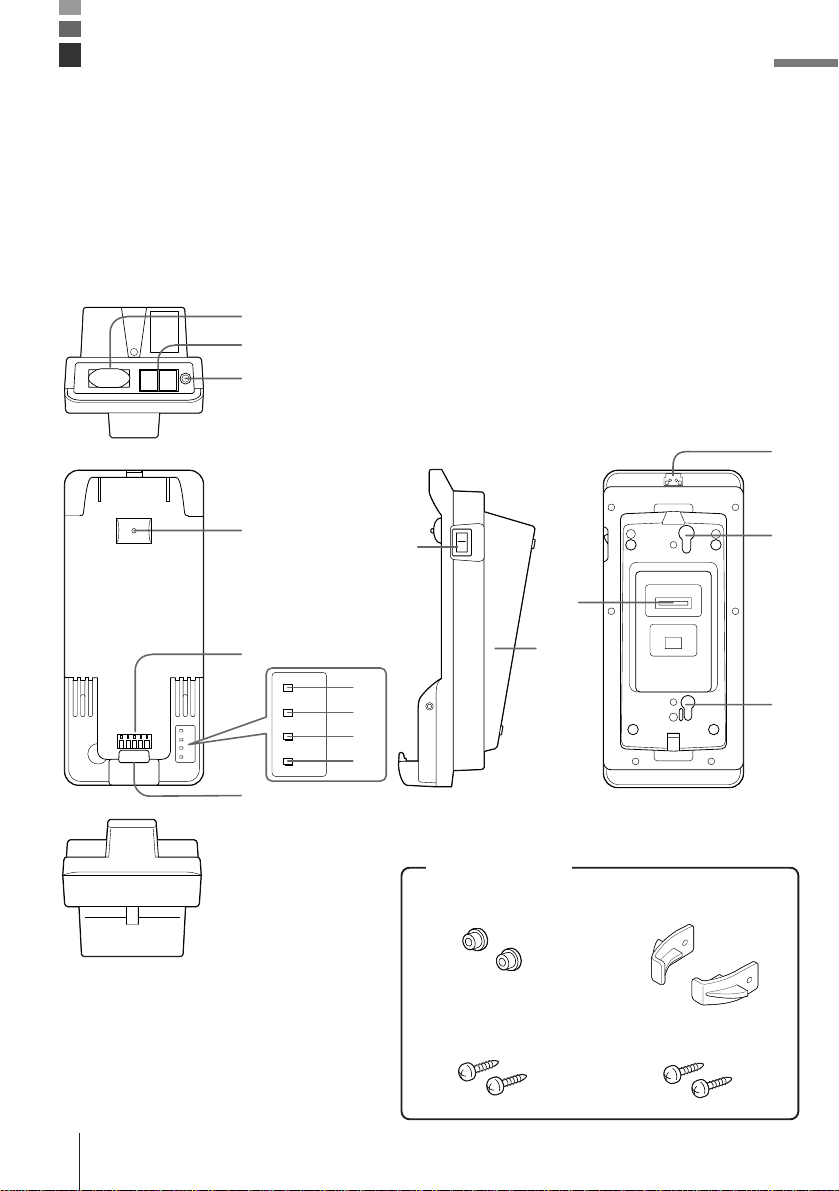
General Guide
1
2
3
14
4
5
10
11
13
12
6
7
8
9
15
15
Accessories
Spacers
Wall unit
Wall unit screwsWood screws
E-32
Page 33

1 RS-232C connector For connection of a PC and uploading/downloading of system data
2 RS-422 connectors For connection of multiple optional Optical Communication Units.
3 AC adaptor jack For connection of an AC adaptor to supply power.
4 Data Collector detection switch Detects whether or not the Data Collector is mounted correctly on
5 Charge/Power supply terminal Supplies power to the Data Collector mounted on the Optical
6 System operation indicator Indicates whether or not the system operation is normal. A system
7 Data communication indicator Indicates the status of data communication operations.
8 Charge indicator Indicates the charge status of the lithium-ion battery pack.
9 Power indicator Indicate whether power is on or off, and if the Data Collector is
10 Infrared port This port provides contact-less infrared communication capabilities
11 Power switch Turns power on and off.
12 Base Reverse the position of the base when wall mounting the Optical
13 DIP switches Use these switches to set the operational configuration of the
14 Wall mounting tab Secures the Data Collector when mounting it on a wall.
15 Wall mounting hole Use this hole to attach the Optical Communication Unit to a hook
and file data.
the Optical Communication Unit.
Communication Unit.
operation problem is indicated when this indicator does not light up
green shortly after the Data Collector is mounted onto the Optical
Communication Unit.
Off: All Data Collectors mounted on the Optical Communication
Units are unable to communicate, or there is a system problem.
Lit Green: Normal system operation. One or more of the Data
Collectors mounted on the Optical Communication Units are
communicating.
Off: Not communicating
Flashing Green: Communication in progress
Lit Red: Optical Communication Unit connection problem
Off: Not charging (Data Collector battery compartment
contains alkaline batteries)
Lit Red: Charging
Lit Green: Charging complete
Flashing Red: Battery pack problem
Flashing Green: Charging interrupted because ambient
temperature is outside of allowable range for
charging. Charging will resume when temperature
is back within the allowable range.
mounted.
Off: Power off
Red: Power on, Data Collector not mounted
Green: Power on, Data Collector mounted
with a Data Collector.
Communication Unit.
Optical Communication Unit.
on a wall.
E-33
Page 34
Using the Optional Optical Communication Unit
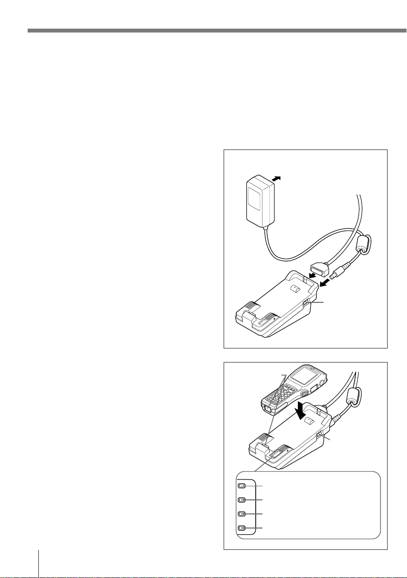
Setting up the Optical Communication Unit and connect the Data Collector
Use only the specified AC Adaptor for Optical Communication Unit to connect to an electrical
outlet. Be sure to connect the AC adaptor and turn on Optical Communication Unit power
before performing any data communication operation with the Data Collector. Power is
supplied to the Data Collector by the Optical Communication Unit.
1 Plug the AC adaptor into an electrical outlet.
2 After making sure that the power switch of the
Optical Communication Unit is in the OFF
position, plug the other end of the AC adaptor
into the AC terminal at the top of the Optical
Communication Unit.
3 After making sure that the power of the Optical
Communication Unit and personal computer is
off, remove the cover and connect one end of
the optional RS-232C cable (DT-881RSC, DT882RSC, DT-883RSC, DT-887AX) to the RS232C connector at the top of the Optical
Communication Unit. Connect the other end of
the cable to the computer’s RS-232C
connector. When the RS-232C connector is
not used, attach the cover.
4 Turn on the Optical Communication Unit
power, which causes the power indicator to
light up red.
5 Attach the Data Collector to the Optical
Communication Unit, making sure their
infrared ports come into close contact with
each other. The color of the Optical
Communication Unit power indicator changes
to green when proper connection is achieved.
• The system operation indicator light up
green when system operation is normal and
the Optical Communication is performing or
standing by for data communication with
another Data Collector connected to an
Optical Communication Unit.
• The data communication indicator flashes
green when a data communication
operation starts.
To electrical outlet
Power switch
(OFF)
Infrared port
Power
switch (ON)
System operation indicator
Data communication indicator
Charge indicator
Power supply indicator
E-34
Page 35

Charging the Battery Pack
The following procedure can be used only when a lithium-ion battery pack is loaded in the
Data Collector.
1 Turn on the power of the Optical
Communication Unit, and confirm that its
power indicator lights up red.
Infrared port
2 Attach the Data Collector to the Optical
Communication Unit, making sure their
infrared ports come into close contact with
each other. The color of the Optical
Communication Unit power indicator changes
to green when proper connection is achieved.
The charge indicator lights up red when
charging starts.
Charge Indicator
Red: Charging
Green: Charging complete
Flashing Red: Defective battery pack
Flashing Green: Temperature outside of
allowable charging range (Charging will
resume with a return to normal
temperature.)
System operation indicator
Data communication indicator
Charge indicator
Power supply indicator
Power
switch (ON)
Important! • If the charge indicator starts to flash red during charging, remove the
battery pack and then reattach it. If this does not solve the problem, it
means that the battery pack is defective and needs to be replaced.
• Use only the specified battery pack.
• Battery packs naturally discharge even when they are not loaded in
the Data Collector. Use a battery pack as soon as possible after
charging it.
• The allowable battery pack charging temperature range is 0°C to 40°C.
Outside this range, charging can result in battery fluid leakage and
generation of heat. It can also cause deterioration of battery pack
performance and shorten battery pack life.
• For best charging results, keep the Optical Communication Unit, Data
Collector and battery pack contacts clean by periodically wiping them
off with a cotton swab or dry cloth.
E-35
Page 36

Using the Optional Optical Communication Unit
Setting the Optical Communication Unit
You can hang the Optical Communication Unit on a wall or use it as a desktop unit.
To use the Optical Communication Unit on a desktop
Simply place the Optical Communication Unit on a
desk, table, or any other flat, stable surface,
rubber feet down. You can even use the wood
screws to anchor the base onto a horizontal
surface. If you do not anchor the base, make sure
you locate the Optical Communication Unit where
there is no danger of it falling.
To hang the Optical Communication Unit on a wall
1 Insert the wall mount unit into the Optical
Communication unit and secure it in place with
the two screws.
2 Remove the two screws that secure the base
of the Optical Communication Unit in place.
E-36
Page 37

3 Move the tab on the upper side of the Optical
Communication Unit.
➀ Remove the two screws on the back that
secure the tab.
➁ Press the tab down to the plate.
➂ Reattach the two screws removed in step ➀
to the holes on the upper side.
4 Pressing in at the four corners of the Optical
Communication Unit base, unhook the tabs
and remove the base from the unit.
Tab
➀
➁
➂
5 Position the base on the wall where you want
to hang the Optical Communication Unit, and
use an awl or some other sharp object to mark
the positions of the two wood screws.
6 Slip a spacer over each of the wood screws
and then drive the screws into the wall at the
positions you marked in the previous step.
Make sure that the spacers are oriented
correctly. You will not be able to hook the
Optical Communication Unit onto the screws if
the spacers are backwards.
E-37
Page 38

Using the Optional Optical Communication Unit
7 Reattach the base to the Optical
Communication Unit, orienting it upside-down
from what it was when you removed it, and
secure it in place with the two screws.
8 Hook the Optical Communication Unit onto the
screws in the wall, and let it slide down to lock
in place.
Important! • Be sure to check the wood screws periodically for looseness and
tighten when necessary after hanging the Optical Communication Unit
on a wall.
Connecting Two or More Optical Communication Units
Up to 7 Optical Communication Units can be connected together using optional 6-6-pin
modular cable (DT-888RSC). This configuration makes it possible to upload and download
data between multiple Data Collector units and a personal computer at the same time.
Configuration
Connect the C-OUT terminal of the
Optical Communication Unit that is
closer to the host computer to the
C-IN terminal of the next unit.
E-38
Page 39
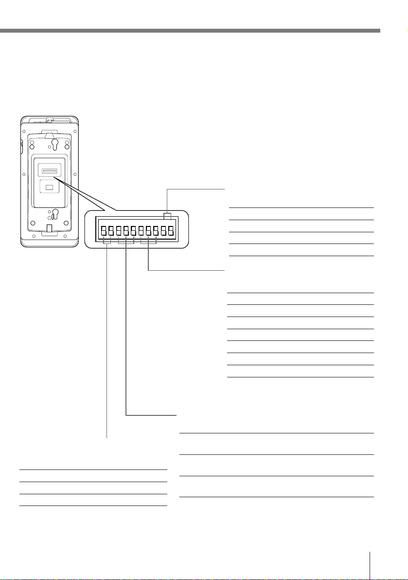
DIP Switch Settings
The settings of the DIP switches located on the bottom of the Optical Communication Unit
can be adjusted to achieve the desired hardware configuration.
Flow Control
910
12345678910
Off OFF OFF
X ON/X OFF ON OFF
RS/CS OFF ON
Use Special Software ON ON
Optical Communication Unit - Host
Computer Communication speed
67 8
2,400bps OFF OFF OFF
4,800bps ON OFF OFF
9,600bps OFF ON OFF
19,200bps ON ON OFF
38,400bps OFF OFF ON
57,600bps ON OFF ON
115,200bps OFF ON ON
* Communication speed can be set by
Data Collector overrides this setting.
Connection T ype
345
Data Collector - Optical Communication
Unit Communication Speed
12
38,400bps OFF OFF
115,200bps ON OFF
230,400bps OFF ON
Host Computer OFF OFF ON (No linking)
Connection OFF (Linking)
Intermediate Unit
in Linked Chain
Terminator Unit
in Linked Chain
ON OFF OFF
ON OFF ON
Important! • Other settings not shown here are used for special-purpose modes,
and should not be used.
E-39
Page 40

Using the Optional Optical Communication Unit
DT-860IOE Optical Communication Unit Specifications
Infrared
Interface: Infrared
Standard: Conformed IrDA Ver. 1.0 Original
Synchronization: Asynchronous
Speed: 9,600/38,400/115,200/230,400bps
RS-232C
Synchronization: Asynchronous
Speed: 2,400 to 115,200bps
Control Protocol: Full-duplex
RS-422
Synchronization: Asynchronous
Speed: 9,600/38,400/115,200/230,400bps
Charger
Charger Type: Fixed voltage (with current limiter)
Charge Time: Approximately 2.5 hours
Power Supply
Method: Special AC adaptor
Current Consumption: Approximately 600mA (when charging)
Functions
Infrared interface
RS-232C interface
RS-422 interface
Dimensions and Weight
Desktop Dimensions: Approximately 110 (W) x 250 (D) x 95 (H)mm
Weight: Approximately 475 g
Wall Mounted Dimensions:
Approximately 110 (W) x 115 (D) x 250 (H)mm
Weight: Approximately 480 g
E-40
Page 41
Using the High-Speed Charger Unit
The optional DT-820CHGE High-Speed Charger Unit provides high-speed charging of a
lithium-ion battery pack (which is not loaded in the Data Collector).
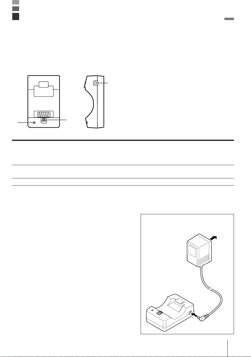
General Guide
3
1
1 Charge indicator Indicates the charge status of the lithium-ion battery pack.
2 Release lever Pull the release lever forward when removing the battery pack from the High-
3 AC terminal For connection of the AC adaptor.
2
Off: Not charging Red: Charging Flashing Red: Defective battery pack
Green: Charging complete Flashing Green: Temperature outside of allowable
charging range (Charging will resume with a return to normal temperature).
Speed Charger Unit.
Charging a Battery Pack
1 Plug the AC adaptor into an electrical outlet.
To
electrical
outlet
2 Plug the AC adaptor cord into the AC
connector on the side of the High-Speed
Charger Unit.
E-41
Page 42

Using the High-Speed Charger Unit
3 Insert the lithium-ion battery pack you want to
charge into the High-Speed Charger Unit with
its terminals facing down.
This causes the CHARGE indicator to light red
to indicate that charging has started.
The following shows how the charge
indicator shows the status of the charge.
Lit Red: Charging
Lit Green: Charge complete
Flashing Red: Battery pack problem
Flashing green: Charging interrupted because
ambient temperature is outside of allowable
range for charging. Charging will resume when
temperature is back within the allowable
range.
It takes about 2.5 hours to attain a full
charge.
4 After the charging operation is complete
(indicated when the CHARGE indicator lights
green), slide the release lever forward and
remove the battery pack from the High-Speed
Charger Unit.
CHARGE indicator
Charging can also be performed
with the lithium-ion battery pack
cover in place.
Release lever
Important! • Never allow the AC adaptor cord to bend too sharply. Doing so can
result in a broken electrical connection.
• If the CHARGE indicator flashes red during charging, remove the
battery pack and re-insert it. If the red flashing continues, it means that
the battery pack is faulty. Replace it with another one.
• Use the High-Speed Charger Unit only to charge the lithium-ion battery
packs specified for it.
• A battery pack naturally discharges after it is charged. Because of this,
you should use a battery pack as soon as possible after charging it.
• This High-Speed Charger Unit is designed to automatically interrupt
charging whenever ambient temperature is outside the range of 0°C to
40°C.
• In order to ensure good speed charge results, keep the terminals of the
High-Speed Charger Unit and battery pack clean by periodically wiping
E-42
them off with a cotton swab or dry cloth.
Page 43

DT-820CHGE High-Speed Charger Unit Specifications
Charger
Charger Type: Fixed voltage (with current limiter)
Charge Time: Approximately 2.5 hours
Power Supply
Method: Special AC adaptor
Current Consumption: Approximately 600mA
Dimensions and Weight
Dimensions: 68 (W) x 108 (D) x 35 (H) mm
Weight: Approximately 95g
E-43
Page 44

○○○○○○○○○○○○○○○○○○○○○○○○○○○○○○○○○○○○○○○○○○○○○○○
○○○○○○○○○○○○○○○○○○○○○○○○○○○○○○○○○○○○○○○○○○○○○○○
○○○○○○○○○○○○○○○○○○○○○○○○○○○○○○○○○○○○○○○○○○○○○○○
○○○○○○○○○○○○○○○○○○○○○○○○○○○○○○○○○○○○○○○○○○○○○○○
○○○○○○○○○○○○○○○○○○○○○○○○○○○○○○○○○○○○○○○○○○○○○○○
○○○○○○○○○○○○○○○○○○○○○○○○○○○○○○○○○○○○○○○○○○○○○○○
○○○○○○○○○○○○○○○○○○○○○○○○○○○○○○○○○○○○○○○○○○○○○○○
○○○○○○○○○○○○○○○○○○○○○○○○○○○○○○○○○○○○○○○○○○○○○○○
○○○○○○○○○○○○○○○○○○○○○○○○○○○○○○○○○○○○○○○○○○○○○○○
○○○○○○○○○○○○○○○○○○○○○○○○○○○○○○○○○○○○○○○○○○○○○○○
○○○○○○○○○○○○○○○○○○○○○○○○○○○○○○○○○○○○○○○○○○○○○○○
○○○○○○○○○○○○○○○○○○○○○○○○○○○○○○○○○○○○○○○○○○○○○○○
○○○○○○○○○○○○○○○○○○○○○○○○○○○○○○○○○○○○○○○○○○○○○○○
○○○○○○○○○○○○○○○○○○○○○○○○○○○○○○○○○○○○○○○○○○○○○○○
○○○○○○○○○○○○○○○○○○○○○○○○○○○○○○○○○○○○○○○○○○○○○○○
○○○○○○○○○○○○○○○○○○○○○○○○○○○○○○○○○○○○○○○○○○○○○○○
○○○○○○○○○○○○○○○○○○○○○○○○○○○○○○○○○○○○○○○○○○○○○○○
○○○○○○○○○○○○○○○○○○○○○○○○○○○○○○○○○○○○○○○○○○○○○○○
○○○○○○○○○○○○○○○○○○○○○○○○○○○○○○○○○○○○○○○○○○○○○○○
○○○○○○○○○○○○○○○○○○○○○○○○○○○○○○○○○○○○○○○○○○○○○○○
○○○○○○○○○○○○○○○○○○○○○○○○○○○○○○○○○○○○○○○○○○○○○○○
○○○○○○○○○○○○○○○○○○○○○○○○○○○○○○○○○○○○○○○○○○○○○○○
○○○○○○○○○○○○○○○○○○○○○○○○○○○○○○○○○○○○○○○○○○○○○○○
○○○○○○○○○○○○○○○○○○○○○○○○○○○○○○○○○○○○○○○○○○○○○○○
○○○○○○○○○○○○○○○○○○○○○○○○○○○○○○○○○○○○○○○○○○○○○○○
○○○○○○○○○○○○○○○○○○○○○○○○○○○○○○○○○○○○○○○○○○○○○○○
○○○○○○○○○○○○○○○○○○○○○○○○○○○○○○○○○○○○○○○○○○○○○○○
○○○○○○○○○○○○○○○○○○○○○○○○○○○○○○○○○○○○○○○○○○○○○○○
Page 45

Printed on recycled paper.
Imprimé sur papier recyclé.
Gedruckt auf wiederverwertetem Papier.
Imprimé au Japon
Printed in Japan
PN430009-001 AB0102-002004B
 Loading...