

Page 1

Supported Equipment Manual
For the DT-800RF Device Manufactured by Casio
Page 2

Copyright © 1996 - 2006 by Connect, Inc.
All rights reserved. This document may not be reproduced in full or in part, in any form,
without prior written permission of Connect Inc., 1701 Quincy Avenue, Suites 5 & 6,
Naperville, IL 60540.
Connect, Inc. makes no representation or warranties with respect to the contents
of this document and specifically disclaims any implied warranties of
merchantability or fitness for any particular purpose. Further, Connect, Inc.
reserves the right to revise this publication and to make changes to it from time to
time without obligation to notify any person or organization of such revision or
changes.
Trademarks
PowerNet OpenAir™, OpenAir Linux™, OpenAir Windows™, OpenAir 400™,
PowerNet Twin Client™, and PowerNet AirLinc™ are trademarks of Connect,
Inc.
Other product names mentioned in this manual may be trademarks or registered
trademarks of their respective companies and are hereby acknowledged.
Production
This manual was written, edited, and produced by:
Connect, Inc.
1701 Quincy Avenue,
Suites 5 & 6
Naperville, IL 60540
www.connectrf.com
Printed in the U.S.A.
Please let us know about any errors in this document at:
http://207.241.78.223/isoxpert/calltrak.nsf/WebTracking?OpenForm
Page 3

Table of Contents
Chapter 1 • Introduction............................................................................................. 1-1
Description………………… ..........................................................................................1-1
Picture………………………...........................................................................................1-2
Setup Requirements…….. ...........................................................................................1-2
Accessories……………….............................................................................................1-2
Operating System………… ..........................................................................................1-4
Chapter 2 • Terminal Setup........................................................................................ 2-1
Running Setup from a Download File ........................................................................2-1
Installation………………… ...........................................................................................2-2
Running the Manager…… ………………………………………………………………….2-4
Quick Start………………… ........................................................................................... 2-5
Configuring the Manager....................................................................................2-5
Configuring the Terminal for Download.............................................................. 2-9
Terminal Settings .............................................................................................2-10
Starting a Telnet Session .................................................................................2-11
Standard Setup……………......................................................................................... 2-12
Setup Using Twin Client Manager.................................................................... 2-12
Terminal Setup Using Twin Client Menus ........................................................2-18
Authorizing PowerNet....................................................................................... 2-20
Software Management……........................................................................................ 2-22
Auto-Configuration ...........................................................................................2-22
Chapter 3 • Keypad Configuration ............................................................................ 3-1
Keypad Figures…………… ..........................................................................................3-1
Keypad Table……………… ..........................................................................................3-4
Chapter 4 • Error Message Resolution Guide .......................................................... 4-1
Supported Equipment Manual
•
March, 2006 iii
Page 4

This page is intentionally blank.
iv Supported Equipment Manual • March, 2006
Page 5

Description
The DT-800RF has a versatile high-speed scanning (100 scans per second) that
ensures a rapid first-time read rate and high data integrity. Its combination of
distance and contact laser scanning allows bar codes to be easily read even when
badly printed on curved and irregular surfaces. Amongst the lightest weight
terminals in its class, the compact lightweight design of the DT-800RF reduces
operator fatigue over extended usage periods. Its backlit display can be illuminated,
enabling readings to be clearly seen in the darkest of work environments.
This terminal has a world-class water splash proof (IPX II standard) that provides
continuous operations, even in the rain. Using the latest multi-drop communications
technology, data can be collected at many different networked points connected to a
single PC. Low-power circuitry and an automatic power-off feature conserve battery
life to the maximum and provide more usage time before replacement. A
rechargeable battery reduces the need to dispose of dead batteries and helps to
conserve the environment.
The DT-800RF’s 160 x 160-dot screen displays extensive lines of information. This
touch screen can also be used for entering data quickly and easily. You may choose
between 2.6 or 10 Mbytes of memory to meet your specific requirements. Control
functions (such as “Help” or “Send”) can be assigned to the DT-800RF special
function keys to further enhance operation.
Master I/O boxes, including SCSI or Ethernet connection, allow the configuration of
a large-scale system with satellite I/O boxes for high speed, large volume data
transfer. The DT-800RF can be set to read all common bar code symbologies with a
narrow bar width as small as 0.125mm. Infrared communications on this terminal
allow data to be downloaded or uploaded without the need to connect any cables,
thus ensuring trouble-free connection to a host system.
Chapter 1 • Introduction
For more information, contact
Supported Equipment Manual
www.casio.com.
•
March, 2006
1-1
Page 6

Introduction
Picture
Setup Requirements
Installation of PowerNet Twin Client requires, at a minimum, the following:
• A Pentium-class processor
• 32 MB of RAM
• 10 MB of free hard disk space available
• Microsoft Windows 95, 98, ME, XP, or NT/2000 operating system
Accessories
The following accessories are available for the DT-800RF:
I/O Box
• DT-860IOE (satellite I/O box)
• DT-865IOE (master I/O box)
Charger (Single-Pack)
• DT-820CHGE (Quick charger)
Lithium Ion Battery Pack
• DT-823LI
1-2
Supported Equipment Manual • March, 2006
Page 7

Accessories
AC Adaptors
• DT-9020ADPG (AC adaptor (230V) for DT-820CHGE)
• DT-9020ADPU (AC adaptor (120V) for DT-820CHGE)
• DT-825ADP-G (AC adaptor (230V) for I/O boxes)
• DT-825ADP-U (AC adaptor (120V) for I/O boxes)
Cables
• DT-881RSC-E: RS232C Modem cable
• DT-882RSC-E: RS232C Cross cable
(between DT860IO-E and PC: 25pin male)
• DT-883RSC-E: RS232C Cross cable
(between DT860IO-E and PC: 25pin female)
• DT-887AX: RS232C Cross cable
(between DT860IO-E and PC: 9pin female)
• DT-888RSC: Modular Cable
• DT-889AX: Cable (between DT-800RF and PC)
• SB-751HF: SCSI cable
(between DT865IO-E and PC: Centro 50pin full male)
• SB-752HH: SCSI cable
(between DT865IO-E and PC: Centro 50pin half male)
• SB-753HP: SCSI cable
(between DT865IO-E and PC: Pin type half 50pin male)
Supported Equipment Manual • March, 2006
1-3
Page 8

Introduction
Operating System
Version of the Operating System
The version of the operating system on a DT-800RF terminal is 2.00.
Finding the Version of the Operating System
The version of operating system will appear on a terminal screen when the terminal is
rebooted. For rebooting instructions, see Command Mode Boot in the Quick Start
section.
1-4
Supported Equipment Manual • March, 2006
Page 9
Chapter 2 • Terminal Setup
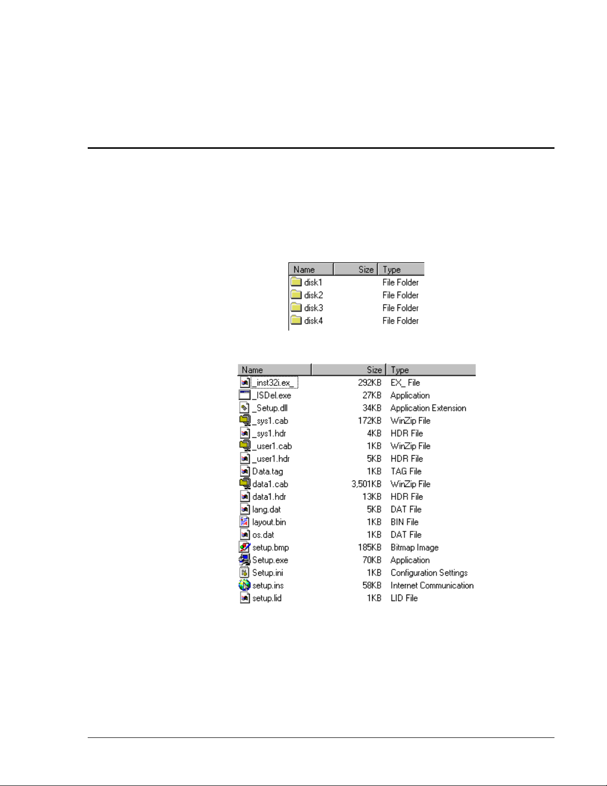
Running Setup from a Download File
The downloaded file is a compressed archive. After extraction using a utility such as
WinZip or PKWARE, folders are created on the hard disk as shown in the following
figure.
Click on the
Disk1 folder to view the files as shown in the following figure.
Click on the
for further instructions.
Supported Equipment Manual
Setup application and proceed to the following section entitled Installation
•
March, 2006
2-1
Page 10

Terminal Setup
Installation
The InstallShield wizard runs and presents the following screen.
Click on Next to begin the installation process.
2-2
Supported Equipment Manual • March, 2006
Page 11
Installation
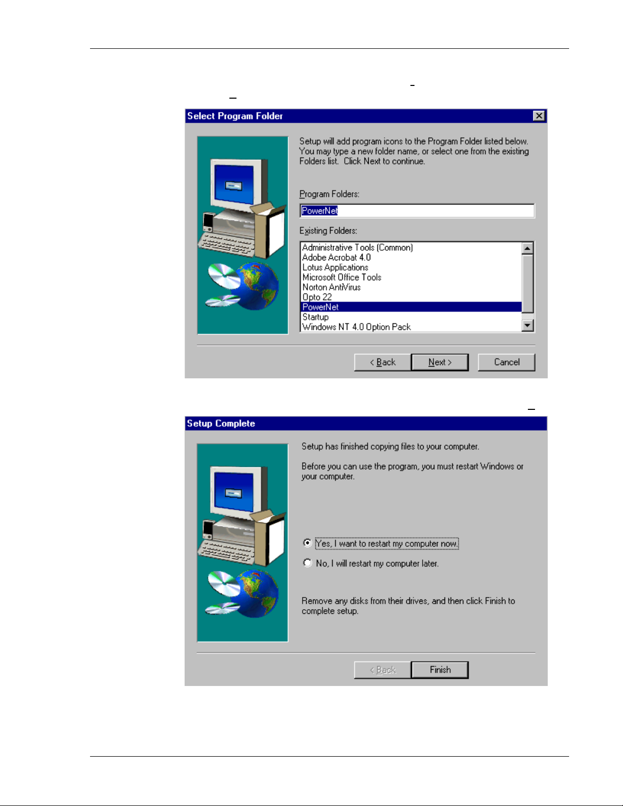
To change the default Destination Location, click on Browse and select a location.
Then click on
Next.
The default folder is
PowerNet. This default may be changed either by selecting an
existing program group or by typing in a new name at the prompt. Then click on
Next.
When the installation is complete, reboot the system to initialize the Twin Client
software.
Supported Equipment Manual • March, 2006
2-3
Page 12
Terminal Setup
a. To reboot the system immediately, click on Finish.
b. To reboot later, click on the option to restart the computer later, and click on
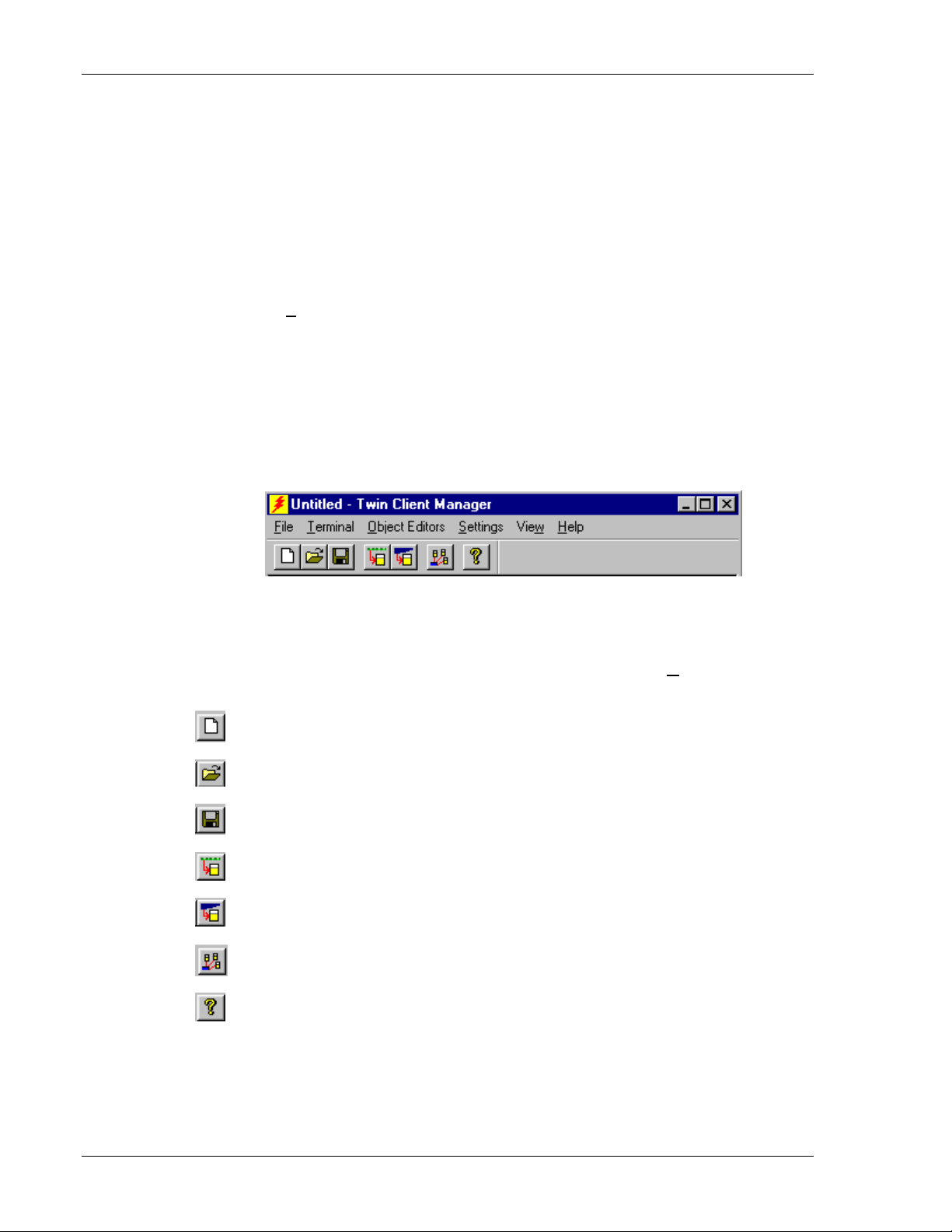
Running the Manager
The PowerNet Twin Client Manager is the utility that manages the terminal software and
configurations.
Select
Start, Programs, PowerNet, and Twin Client Manager. The PowerNet Twin
Client Manager screen appears as shown in the following figure. This is the
administrator's main screen, and all functions are accessed from its menu bar, tool bar,
and tabs.
Menu Bar
The menu bar provides access to the functions used to configure the terminals and
manage their software.
Finish.
Toolbar
Under the menu bar, the tool bar provides shortcuts to major features. The toolbar can be
turned on or off by changing the Toolbar parameter found on the
shortcuts available from the toolbar are as follows:
Create a new terminal configuration.
Open an existing terminal configuration.
Save the current terminal configuration.
Download the configuration to terminal.
Download software to terminal.
Configure terminals automatically over the wireless network.
View PowerNet Twin Client Manager version.
View menu. The
The PowerNet Twin Client Manager is now successfully installed and ready for use. The
Quick Start section below provides detailed instructions for quickly configuring the
terminal and starting a telnet session.
2-4
Supported Equipment Manual • March, 2006
Page 13
Quick Start
Quick Start
Quick Start describes how to prepare the Twin Client Manager and the Casio terminal for
a Telnet session with the host. Following an initial serial download, the terminal software
and configuration is managed automatically, over the wireless network.
Configuring the Manager
The first step is to configure the Twin Client Manager to meet site-specific requirements,
and then prepare it for the automatic management of the terminal software and IP
addresses. This simple procedure will require only a few minutes to complete.
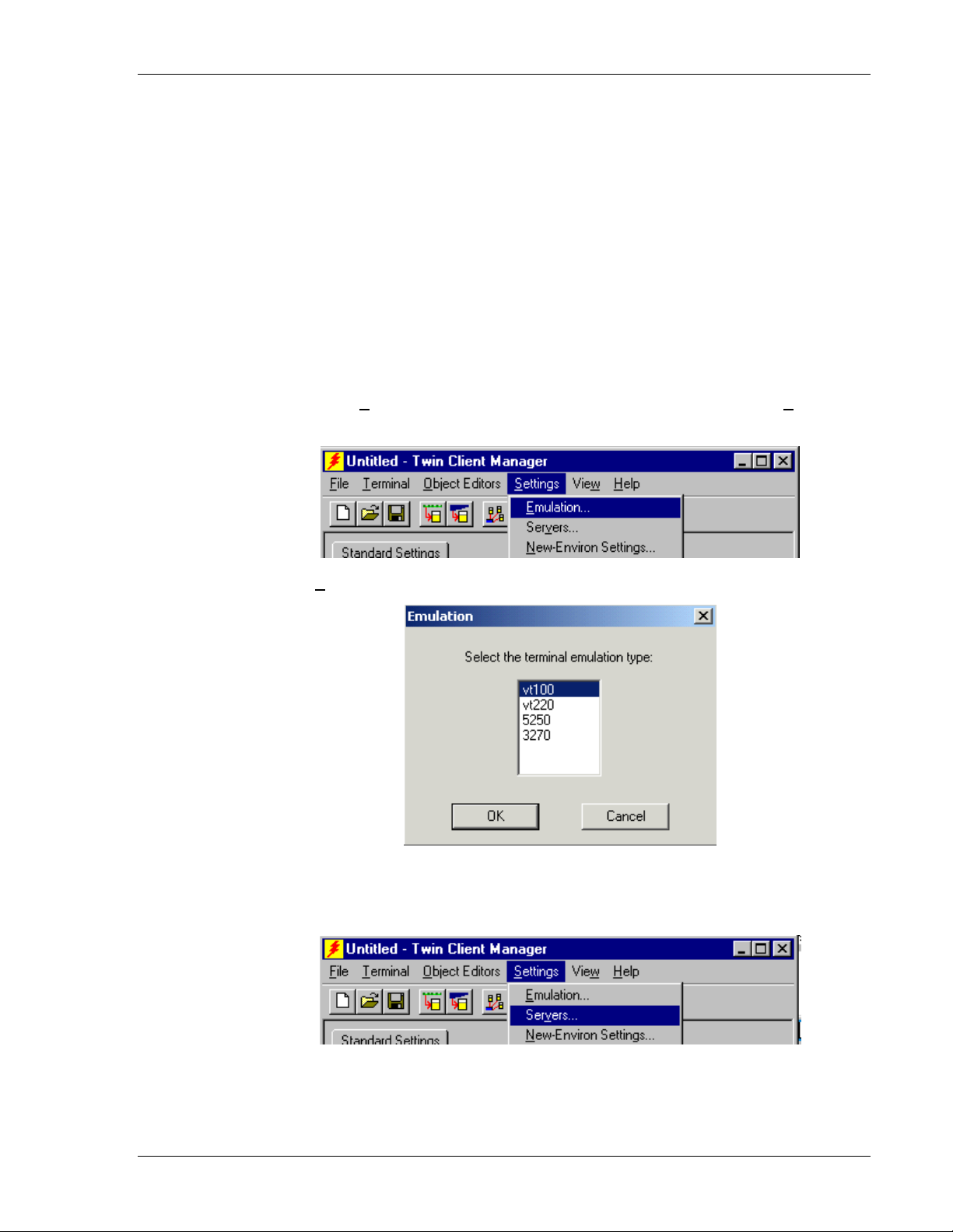
Setting the Emulation
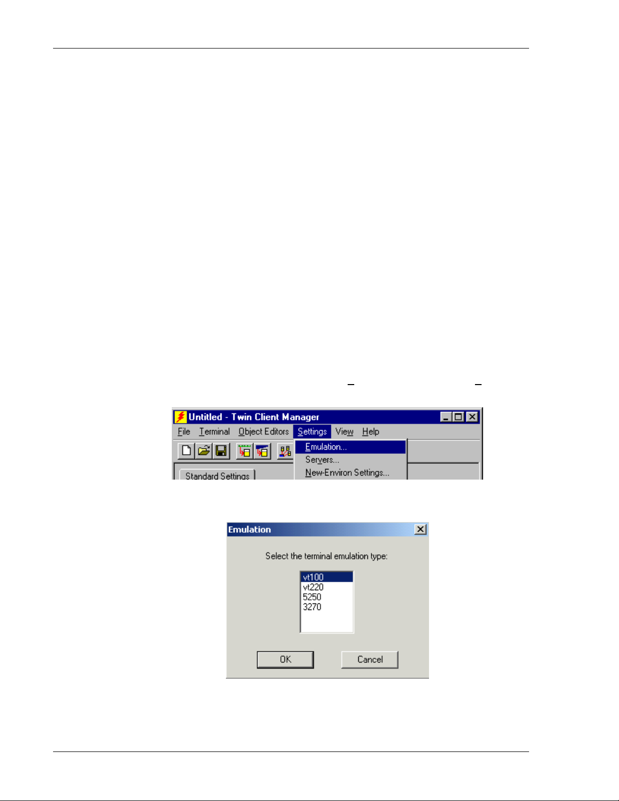
Click on Start, Programs, PowerNet, and Twin Client Manager. Select the Settings
menu, as shown below.
Click on
Emulation, select the desired emulation, and click on OK.
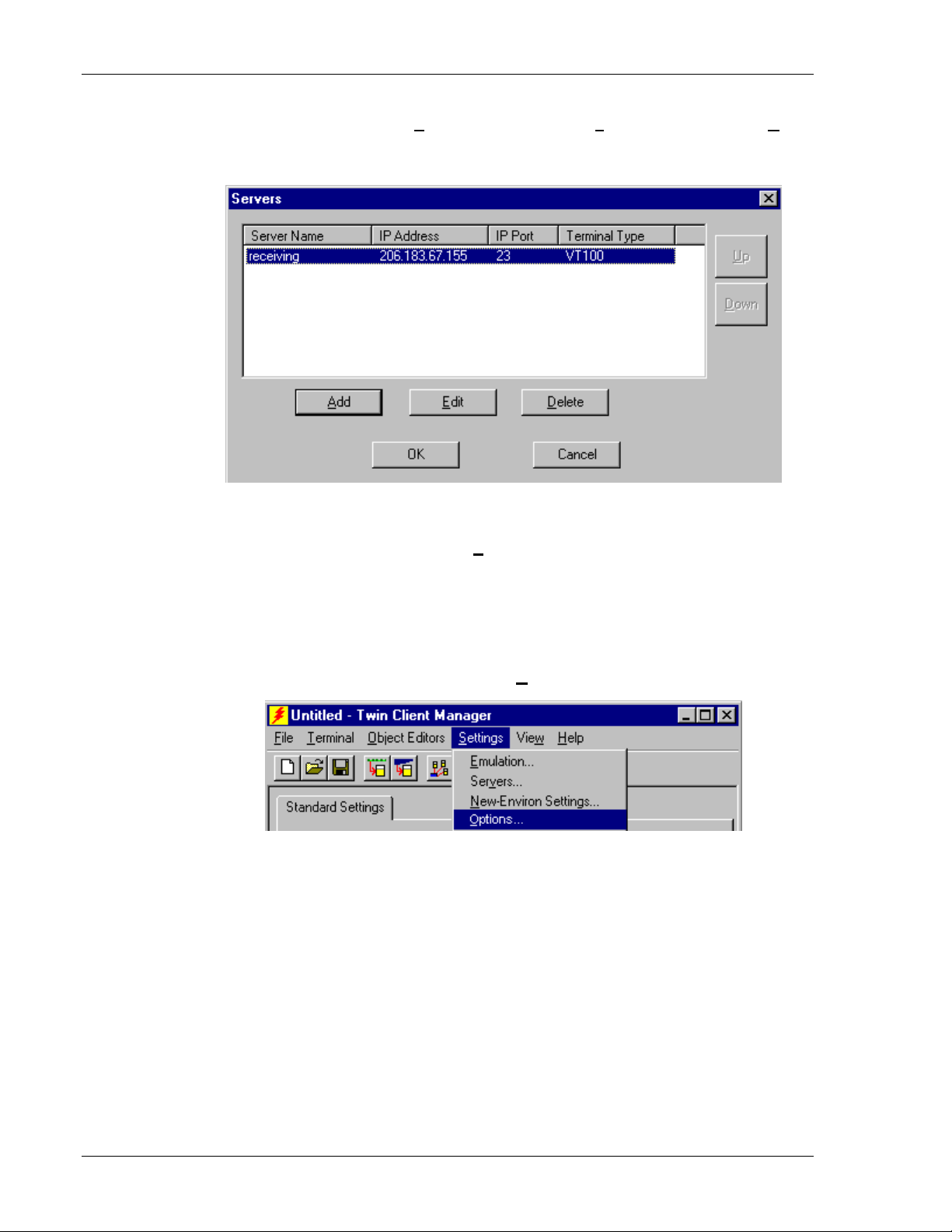
Setting the Servers
The Servers are the Telnet host systems the terminals will access.
Supported Equipment Manual • March, 2006
2-5
Page 14
Terminal Setup
To set these addresses from the Settings menu, click on Servers and then click on Add.
Enter the name of each server, its IP Address and IP port (normally 23 for Telnet
servers), and emulation type. Then click on
OK.
Repeat this step for each telnet server the terminals are required to access. If an error is
made in the name, IP Address, IP Port number, or Terminal emulation type, click on the
line that is in error and then click on the
Edit button to make the corrections.
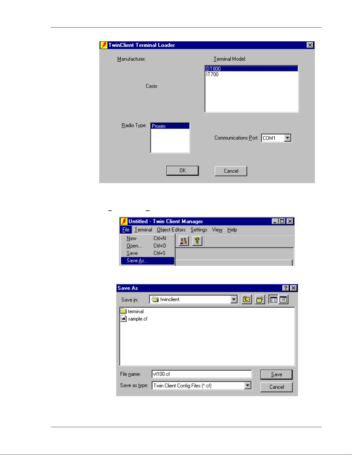
Setting Terminal Model and COM Port
The default terminal model is DT800, and the default serial connection to the Casio
cradle is through
change the
The default terminal model,
under PowerNet. To maintain compatibility with existing Casio Telnet client keyboard
layouts, a specific terminal model and keypad must be selected from the Terminal Model
window.
COM1. To select a specific Casio terminal model and keypad, or to
COM port assignment, click on the Options menu as shown.
DT800, represents the default setup for all Casio terminals
2-6
Supported Equipment Manual • March, 2006
Page 15
Quick Start
Saving the Configuration
Click File and Save As. Enter a name for this configuration.
For the purposes of this example, the name is
vt100.
Supported Equipment Manual • March, 2006
2-7
Page 16
Terminal Setup
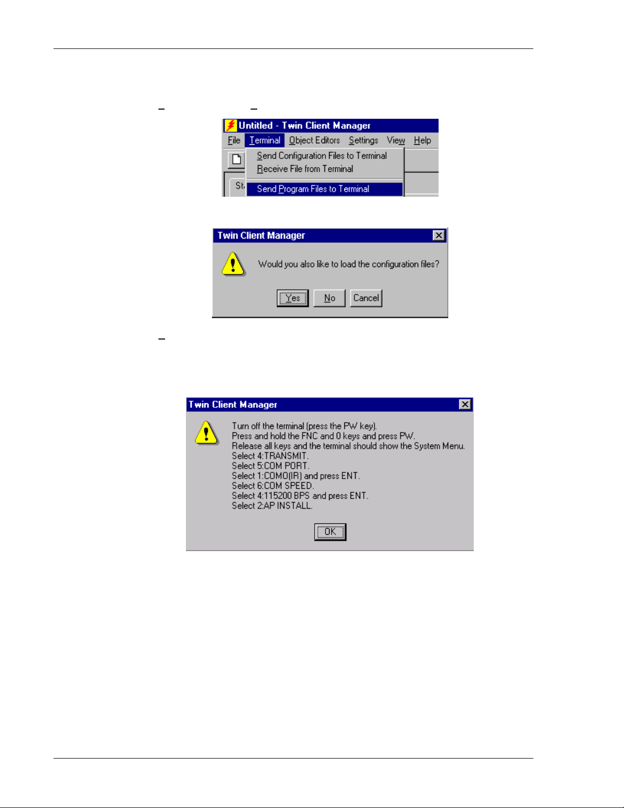
Download Files to Terminal
Select Terminal and Send Program Files to Terminal from the menu bar.
The program asks if you want to include configuration files.
Yes.
Select
The
Casio Load Options screen appears telling you what actions to perform on the
terminal. The first three of these instructions perform the terminal reboot. The remainder
perform the actual download.
Click
OK.
The Casio CD-ROM, distributed with Casio terminals, contains LMWIN2 in the
directory \Tool\Dt800\LMWIN201. Copy the LMWIN2 utility into any directory on your
PC. Next, install the PowerNet Twin Client software on the Casio terminal. To do this,
connect the serial load cable from a serial port on the PC to the communications port of
the terminal cradle or to a Casio terminal.
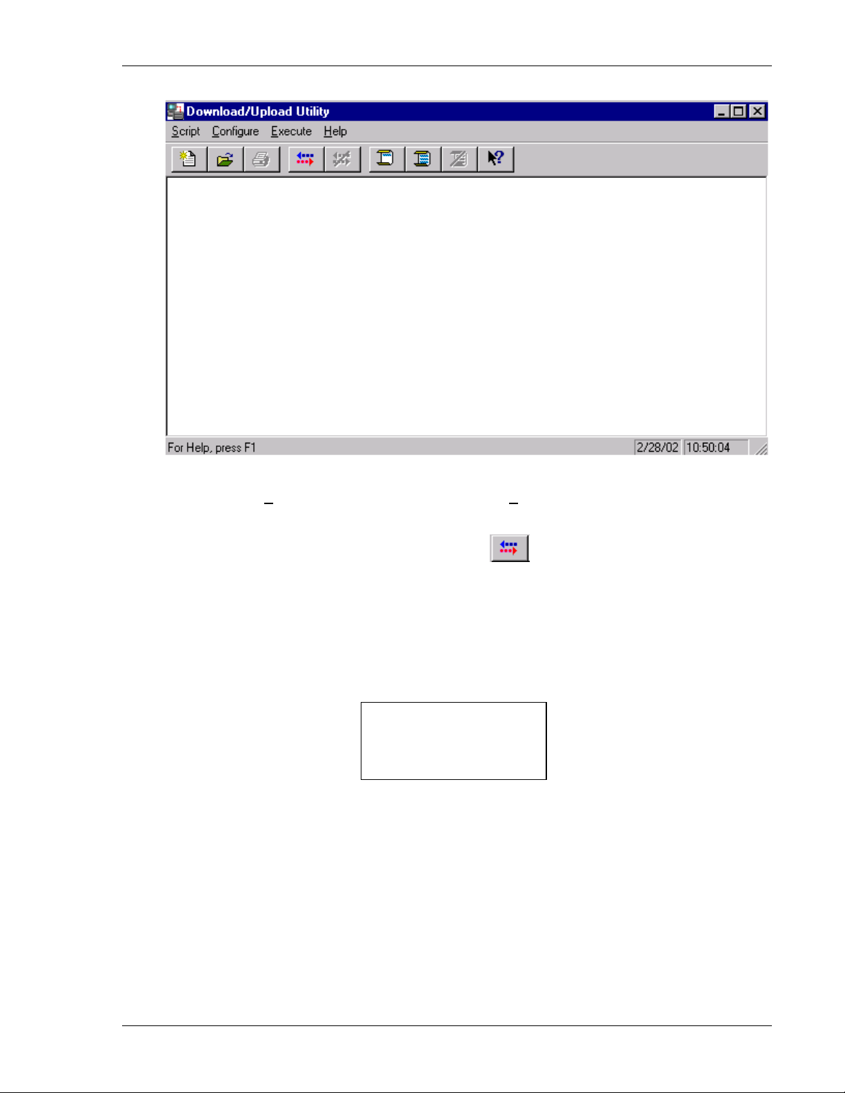
On the PC, the Download/Upload Utility screen is displayed. Note that this program is
LMWIN.EXE, which is distributed separately.
2-8
Supported Equipment Manual • March, 2006
Page 17
Quick Start
Execute from the menu bar, then select Link Manager and select Start Link
Select
Manager
Note: A shortcut is to just click on the start icon.
To stop the download, select
.
Execute then Link Manager Stop, or press the Stop key,
the fifth icon from the left under the Download/Upload Utility menu.
After the files are sent, close the Download/Upload Utility to return to the Twin Client
Configuration Utility main screen and proceed.
The PowerNet Twin Client startup screen is displayed on the terminal as follows.
Note: The date of 2006 is updated on the terminal at the time of a new release.
Twin Client
© 1991-2006 Connect,
Inc.
Keypress to Continue
The terminal is now ready to establish a telnet session with the Host system.
Configuring the Terminal for Download
The terminal is prepared for the addition of Twin Client by booting to command mode,
and setting the serial port parameters as described in this section. This simple procedure
is described in the following sections, and requires only a few minutes to complete.
Supported Equipment Manual • March, 2006
2-9
Page 18

Terminal Setup
Connecting the Cradle
The terminal download requires a serial connection between the terminal and the PC
through a cradle. Connect the serial load cable from a serial port on the PC to the
communications port of the terminal cradle or to a Casio terminal.
In preparation for this download perform the following:
• Make sure you have copied the LMWIN utility to any directory on your PC.
• Connect the selected serial port on the PC to the cradle with a null modem cable. Use
COM Port 1.
• Verify that the cradle is powered on.
• If you are using a cradle, configure the cradle baud rate to 115200.
• Set the dip switches on the bottom of the cradle. There are ten switches. The up
position of a switch is the on position. The settings for the ten switches are shown
below to set the cradle baud rate to 115200.
Switch 1 2 3 4 5 6 7 8 9 10
Setting On Off Off Off On Off On On On On
When using a cable, the baud rate to select is also 115200.
Terminal Settings
Command Mode Boot
On the portable terminal, power the terminal OFF, then boot the terminal using the key
sequence as shown in the following table.
Command Mode Boot Sequences
Following Power OFF
Terminal Model & Keypad Key Sequence
DT-800RF
The System Menu is displayed.
1. EXECUTE AP
2. SET MODE
3. DATE/TIME
4. TRANSMIT
5. CALIBRATION
6. VERSION
7. SS UTILITY
1. Select
7: SS Utility and then 1: Environment.
2. Enter the IP Address, Netmask, Gateway, Domain, etc.
Press the FNC and 0 keys,
then press and release the
then release the
SYSTEM MENU
FNC and 0 keys.
PWR key,
2-10
Supported Equipment Manual • March, 2006
Page 19

Quick Start
3. Press the Clear key.
4. Select
5. Press the
6. Select
7. Enter
8. Select
9. Press the
10. Select
11. Select
1: yes.
Clear key to return to the system menu.
4: Transmit, 4: Utility and 4: Change memory size.
640 and then press the Enter key.
yes to change the size.
Clear key to return to the system menu.
1: Execute AP.
Enter for “yes” to execute the AP.
The terminal is now configured to accept a download from Twin Client Manager.
Starting a Telnet Session
At the Twin Client main menu on the terminal, press any key to establish the connection.
Until the terminal has been authorized, the following screen is displayed.
RECOVERABLE ERROR
Terminal not
Authorized for
Twin Client
Keypress to Continue
It is not necessary to authorize the terminal at this time, so press any key to continue. The
terminal will establish a connection with the host system and start emulation. If the
terminal fails to connect to the host, refer to the following table for the possible causes
and the related corrective actions.
Failure Cause Corrective Action
Incorrect Host IP address Correct the Host List address on the terminal. Refer to
Terminal Setup Using Twin Client Menus under Standard
Setup for instructions.
Incorrect netmask value Access Radio Setup menu and correct the netmask value.
Refer to Terminal Setup Using Twin Client Menus for
instructions.
After a Telnet session has been successfully established, the terminal will remain in
session for a maximum of 30 minutes at a time until it has been authorized. Once
authorized, there is no software restriction on the session time. The instructions for
authorizing the terminal are presented in Authorizing PowerNet.
Supported Equipment Manual • March, 2006
2-11
Page 20
Terminal Setup
Standard Setup
The default terminal setup is sufficient for most installations. However, to meet sitespecific requirements, it may be necessary to customize terminal operation. The standard
setup options simplify this process and can be modified using one of the following
methods:
• Using the Twin Client Manager.
• Using the Twin Client terminal menu system.
Standard Setup describes how to use the Twin Client Manager and the terminal menu
systems to set up the terminal. Also described are the methods for authorizing the
terminal software.
Setup Using Twin Client Manager
The Twin Client Manager provides a Standard Settings tab for automatic setup of the
terminals. The options within this tab vary according to the emulation selected, each of
which is described below.
VT Settings
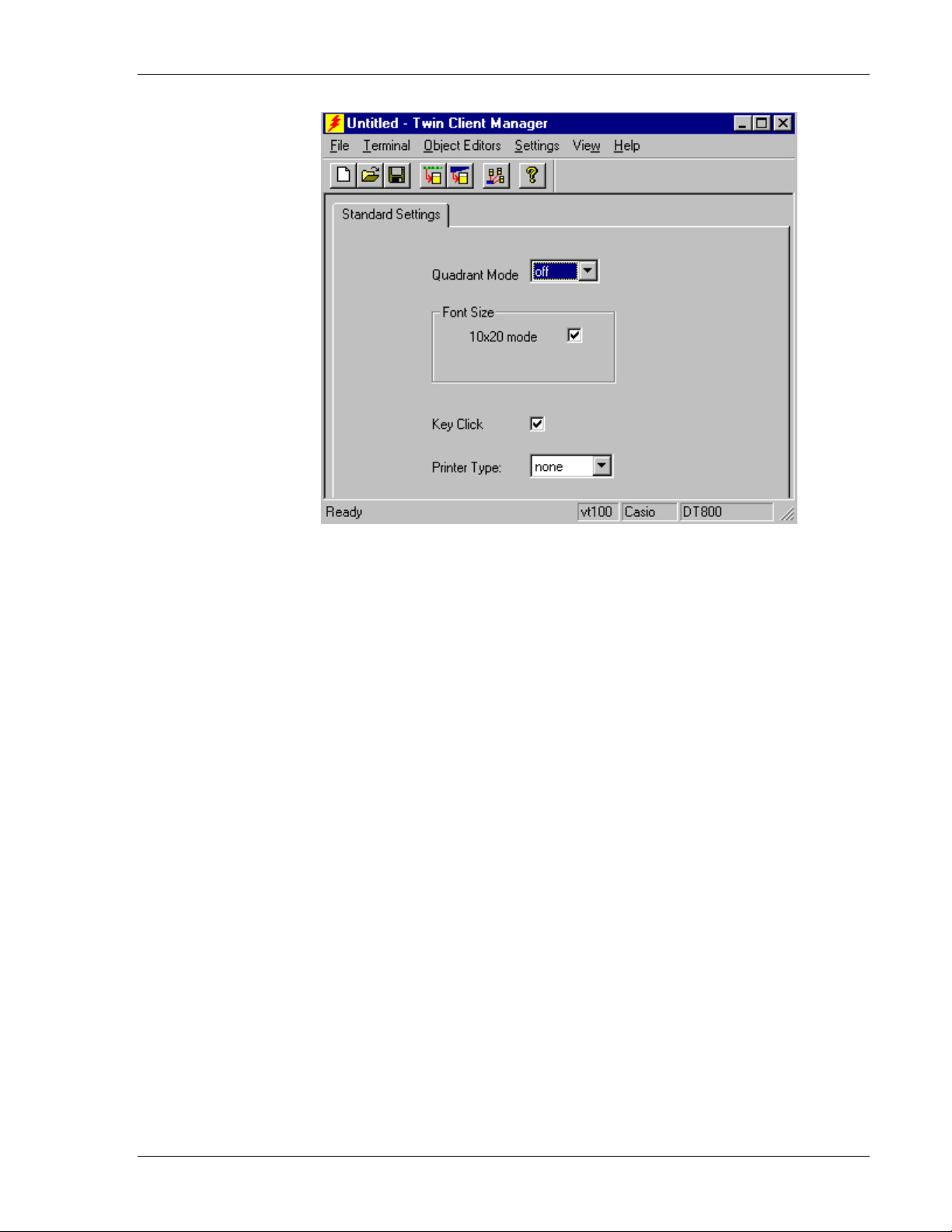
Select the VT emulation setup by clicking on the Settings menu and then the Emulation
menu, as shown below.
Then click on the VT100 or VT220 selection, as shown below.
Click on OK after the selection is made, and return to the main Twin Client Manager
menu. The standard settings tab will now reflect the settings for VT emulation.
2-12
Supported Equipment Manual • March, 2006
Page 21
Standard Setup
Quadrant Mode
The scrolling list defines the rules by which the terminal display is positioned in the
larger host display. As defined by Twin Client, quadrants are fixed position “windows”
in the host display, and the terminal display is located on whatever quadrant contains the
current cursor position.
Off disables quadrant processing and Twin Client simply centers the current host
input field in the terminal display.
On enables quadrant processing. However, input fields that cross quadrant
boundaries result in a shift to the left in order to locate as much of the current input
field on the terminal display.
Soft always positions on a quadrant boundary regardless of input field boundaries.
Viewing keys are enabled.
Hard is the same as Soft except the viewing keys are disabled.
Lock locks the terminal display origin (upper left corner) to fixed row and column
(x,y) coordinates in the host display. The coordinates are zero-based.
Font Size
This check box enables (checked) or disables (unchecked) the display of characters in
10x20 font.
Key Click
This check box enables (checked) or disables (unchecked) audible key clicks from the
terminal. Default is on (checked).
Supported Equipment Manual • March, 2006
2-13
Page 22
Terminal Setup
Printer Type
This scrolling list selects the attached printer type. The default value is none, indicating
no printer is attached.
5250 Settings
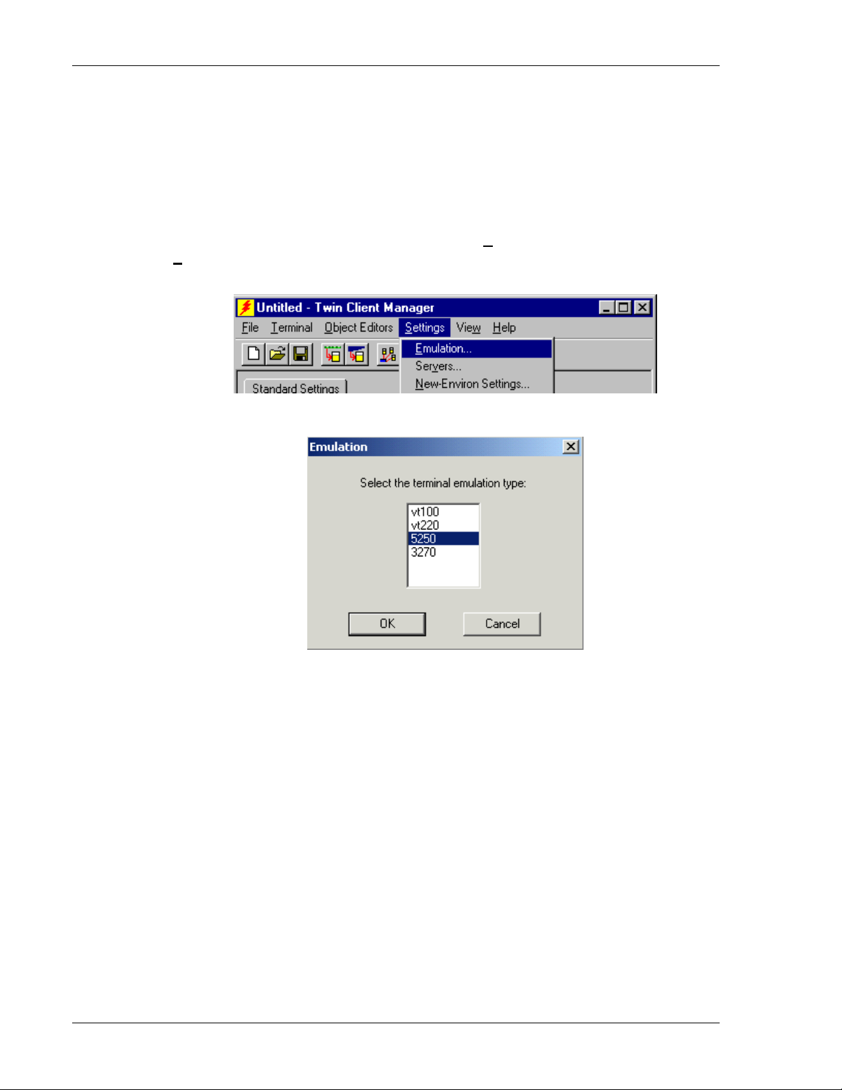
Select the 5250 emulation setup by clicking on the Settings menu and then the
Emulation menu, as shown below.
Then click on the 5250 selection, as shown below.
Click on OK after the selection is made, and return to the main Twin Client Manager
menu. The standard settings tab will now reflect the settings for 5250 emulation.
2-14
Supported Equipment Manual • March, 2006
Page 23

Standard Setup
Quadrant Mode
The scrolling list defines the rules by which the terminal display is positioned in the
larger host display. As defined by Twin Client, quadrants are fixed position “windows”
in the host display, and the terminal display is located on whatever quadrant contains the
current cursor position.
Off disables quadrant processing and Twin Client simply centers the current host
input field in the terminal display.
On enables quadrant processing. However, input fields that cross quadrant
boundaries result in a shift to the left in order to locate as much of the current input
field on the terminal display.
Soft always positions on a quadrant boundary regardless of input field boundaries.
Viewing keys are enabled.
Hard is the same as Soft except the viewing keys are disabled.
Lock locks the terminal display origin (upper left corner) to fixed row and column
(x,y) coordinates in the host display. The coordinates are zero-based.
Font Size
This check box enables (checked) or disables (unchecked) the display of characters in
10x20 font.
Key Click
This check box enables (checked) or disables (unchecked) audible key clicks from the
terminal. Default is on (checked).
Supported Equipment Manual • March, 2006
2-15
Page 24

Terminal Setup
Printer Type
This scrolling list selects the attached printer type. The default value is none, indicating
no printer is attached.
3270 Settings
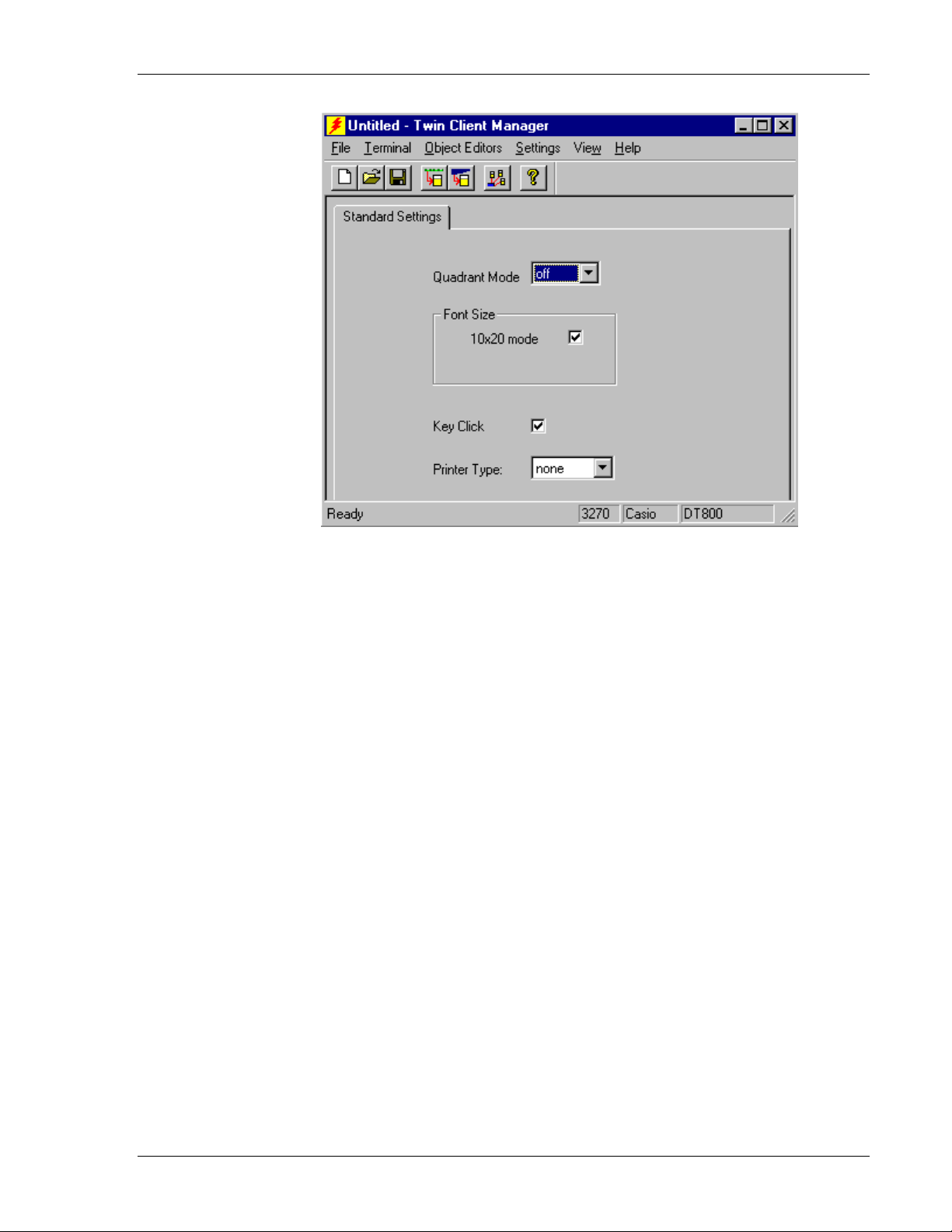
Select the 3270 emulation setup by clicking on the Settings menu and then the
Emulation menu, as shown below.
Then click on the 3270 selection, as shown below.
Click on OK after the selection is made, and return to the main Twin Client Manager
menu. The standard settings tab will now reflect the settings for 3270 emulation.
2-16
Supported Equipment Manual • March, 2006
Page 25
Standard Setup
Quadrant Mode
The scrolling list defines the rules by which the terminal display is positioned in the
larger host display. As defined by Twin Client, quadrants are fixed position “windows” in
the host display, and the terminal display is located on whatever quadrant contains the
current cursor position.
Off disables quadrant processing and Twin Client simply centers the current host
input field in the terminal display.
On enables quadrant processing. However, input fields that cross quadrant
boundaries result in a shift to the left in order to locate as much of the current input
field on the terminal display.
Soft always positions on a quadrant boundary regardless of input field boundaries.
Viewing keys are enabled.
Hard is the same as Soft except the viewing keys are disabled.
Lock locks the terminal display origin (upper left corner) to fixed row and column
(x,y) coordinates in the host display. The coordinates are zero-based.
Font Size
This check box enables (checked) or disables (unchecked) the display of characters in
10x20 font.
Key Click
This check box enables (checked) or disables (unchecked) audible key clicks from the
terminal. Default is on (checked).
Supported Equipment Manual • March, 2006
2-17
Page 26

Terminal Setup
Printer Type
This scrolling list selects the attached printer type. The default value is none, indicating
no printer is attached.
Terminal Setup Using Twin Client Menus
The Twin Client terminal software provides an internal menu system for configuring
certain parameters on the terminal and for switching between “server” and “telnet” mode
of operation. To access this menu system, press the uppercase
shown in the following figure.
Twin Client
© 1991-2006, Connect, Inc.
Keypress to Continue
The next screen displays the menu options. Cursor to the appropriate option and press
Enter.
Edit Menu Options
Edit Mobile Unit IP
Edit Server/Host IPs
Edit License Key
Run Site Survey
Switch Client Modes
Run Client Emulator
Exit to OS
C at the startup screen as
Use the Up-Arrow and Down-Arrow keys to navigate the menu, and press Enter to select
the highlighted option. Each menu option is described below.
Edit Mobile Unit IP
The IP list contains the terminal IP address, the Subnet mask, and the Router IP address.
Enter the appropriate address and select
IP 206.232.71.38
SN 255.255.255.0
RT 206.232.71.1
<F3> Save <F7> Quit
F3 to save the configurations.
Press
F3 to save and/or F7 to quit.
Edit Server/Host IPs
If you wish to change the host IP address or addresses using the terminal menus, select
this option and enter up to four Host IP addresses as required.
2-18
Supported Equipment Manual • March, 2006
Page 27

Standard Setup
Host 0
IP 206.183.67.155
Port 23__
<F3> Save <F7> Quit
Press F3 to save the configurations.
Edit License Key
The client software can be authorized automatically, as described in the next section,
Authorizing PowerNet. This menu option permits authorization of each terminal
manually. Select this option to obtain the terminal's Identification Code, which is used to
obtain the Authorization code from the Connect web site, as described in the next section.
The 12-digit value displayed at the top of the terminal screen is the Identification Code
for the terminal.
00A0F826E614
Authorization
______________
not authorized
<F3> Save <F7> Quit
Type the authorization code into the field as it appears on the WEB site. Punctuation
characters, such as the hyphen (-), are not required. Press
F3 to save the authorization
code.
Run Site Survey
This option (a feature of Spectrum 1) is applicable to Release 5.0 and may be obsolete for
your terminal.
Switch Client Modes
The PowerNet Twin Client normally operates in "telnet" mode, which provides direct
connection to Telnet hosts. It can also operate in "server" mode, through a PowerNet
OpenAir server. Select this menu option to switch between server and telnet modes of
operation. Note that the host socket address for the PowerNet OpenAir servers is 1800,
which must also be changed in the
Edit Server/Host IPs menu described at the beginning
of this section.
Run Client Emulator
After all desired changes have been made, select this option to return to the Twin Client
main menu. Then press any key to establish the Telnet session and begin emulation.
Refer to Starting a Telnet Session under Quick Start for further instructions.
Supported Equipment Manual • March, 2006
2-19
Page 28

Terminal Setup
Authorizing PowerNet
Each PowerNet Twin Client will run for 30 minutes at a time without authorization.
Uninterrupted operation for a production environment is the result of authorizing the
software. Authorization codes are obtained from the Connect Website at
http://www.connectrf.com on the Partner Services page. Click on the Generate
Authorization icon at the top of the page.
Manual Authorization
The procedure for manually setting the Authorization code on the terminal is described in
the section entitled
Add Licenses
The Add Licenses feature is used when adding additional licenses to an already site
licensed Twin Client manager. An example of this is the instance in which Twin Client
manager is licensed for 10 licenses, and the customer purchases another 10 licenses to
make a total of 20 licenses.
Edit License Key in Terminal Setup Using Twin Client Menus.
From Twin Client manager, choose
Add Licenses button.
on the
Authorization from under the Settings menu. Click
A pop-up box appears with the machine ID and a space for the additional licenses
authorization code.
2-20
Supported Equipment Manual • March, 2006
Page 29

Standard Setup
Enter the additional license’s authorization code and click on OK.
Use the machine ID in the pop-up box instead of the original machine ID to get your
authorization code.
If adding users, click on the Add Licenses button before generating the authorization
code to get the most current machine ID.
Transfer Authorization
The Transfer Authorization feature is used when moving a site license from one PC to
another. After Twin Client manager is installed on a new PC, you will need the
system/machine ID for it.
From Twin Client manager, select Authorization from under the Settings menu.
Note: This feature only works if there are licenses remaining on the old PC.
Supported Equipment Manual • March, 2006
2-21
Page 30

Terminal Setup
Software Management
In addition to providing functions for the download of files to the terminal via the
traditional serial connection, the Twin Client Manager also provides for the management
of terminal software and configurations automatically over the wireless network.
This section entitled Software Management describes the automated capability in detail.
Additional manual operations involving serial download options are described at the end
of this section.
Auto-Configuration
The Auto-Configuration form is accessed from the Twin Client Manager Settings menu.
Note: If no options are displayed, click the Advanced<< button.
Enabling Automatic Downloads
Click to put a check in the box that allows terminal to be automatically configured via RF
to enable automatic downloading. In the event another PC on the network is already
configured and active, the following warning message is displayed.
2-22
Supported Equipment Manual • March, 2006
Page 31

Software Management
Synchronizing Configuration Files
Click to put a check in the Synchronize Configuration Files box to enable automatic
synchronization of configuration files on the terminal. When the terminal is command
booted, its configuration files will be compared with the most recent on the PC. The
terminal is updated automatically if it does not have the latest revision.
Synchronizing Program Files
Click to put a check in the Synchronize Program Files box to enable automatic
synchronization of program files on the terminal. When the terminal is command booted,
its program files will be compared with the most recent on the PC. The terminal is
updated automatically if it does not have the latest revision.
Automatic IP Address Assignment
New terminals will be assigned IP addresses automatically if the following box is
checked.
Note: Do not check this option if a DHCP server is configured to manage address
assignments.
To set the addresses, click on the
Addresses button to access the Segment Address
Assignments dialog box, as shown in the following figure.
Enter the desired range in the
Add.
Supported Equipment Manual • March, 2006
From and To boxes as shown above, and then click on
2-23
Page 32
Terminal Setup
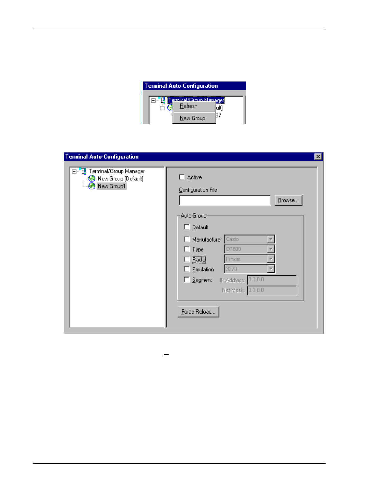
Creating New Groups
New groups, with different configurations, can be created by clicking on Terminal
Group Manager
After the new group has been created, the group settings option becomes available for
change, as shown below.
, and then clicking the right mouse button as shown.
After the Configuration File and all of the other parameters have been set, the group is
made active by clicking on the
2-24
Supported Equipment Manual • March, 2006
Active check box.
Page 33

Software Management
Setting the Segment
Checking the Segment button restricts a terminal group to a range of IP addresses. The
IP Address can be any valid address on the segment, as it is used only to identify the
segment. The setting of the Net Mask can be used to restrict the range. This feature is
useful for segregating terminal groups by location.
Setting Force Reload
Clicking on the Force Reload button forces all terminals within a group to be
automatically updated. The following warning message appears.
Click on the
Yes button to force the reload.
Setting the Default Terminal Group
New terminals that have not yet been assigned to any group are initially assigned to the
default group in effect when they are command booted.
Supported Equipment Manual • March, 2006
2-25
Page 34
Terminal Setup
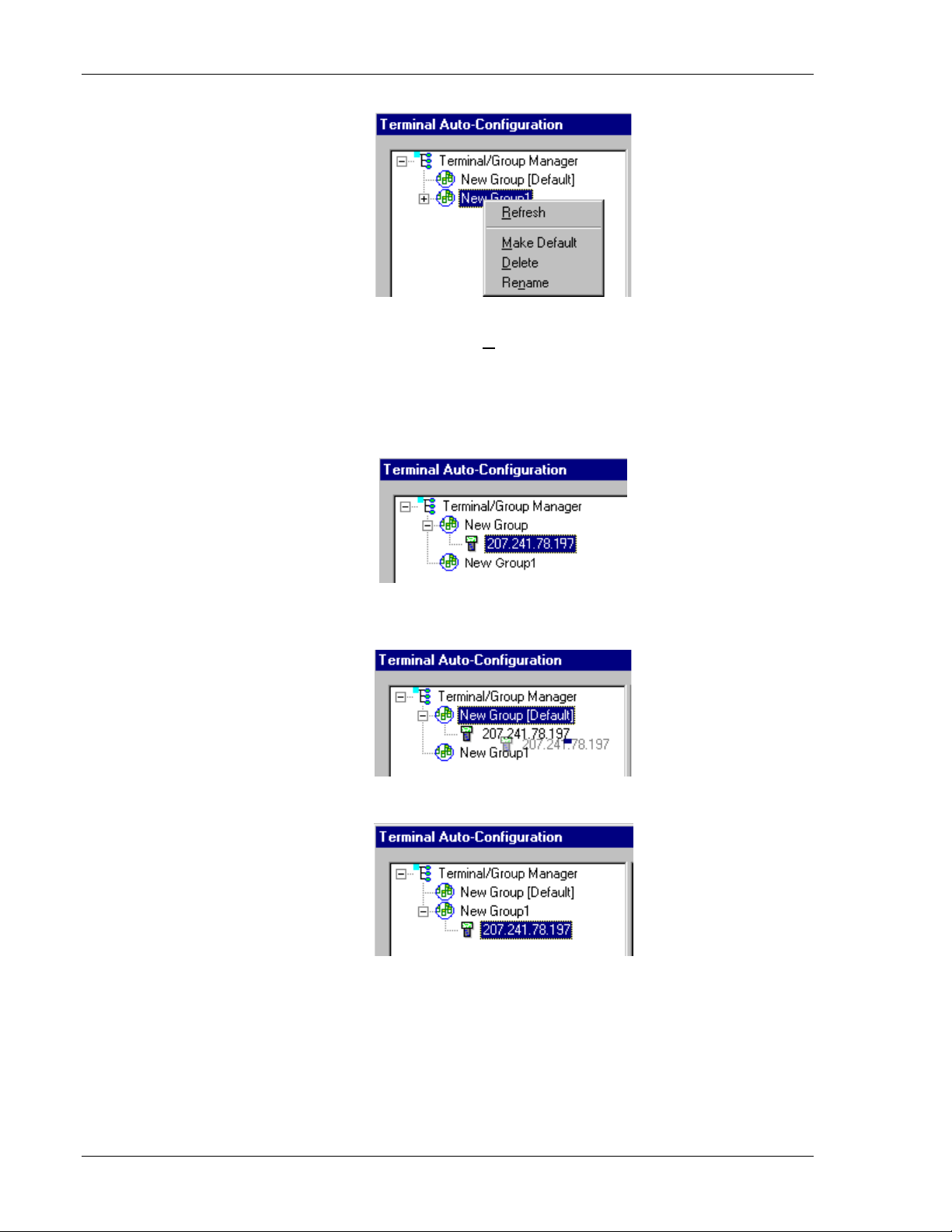
Any group can be made the default group by clicking on the group, and then clicking on
the right mouse button. Then click on the
Make Default option.
Reassigning Terminals
After a terminal has been configured and assigned to the default group, it can be
reassigned to a new group by clicking on the terminal icon as shown below.
Then, holding the mouse button down, drag the terminal icon to the desired group as
shown next.
Release the mouse button, which reassigns the terminal.
The next time the terminal is rebooted, it will be reconfigured as defined in the group
specification.
2-26
Supported Equipment Manual • March, 2006
Page 35

9
8
8
5
0
3
5
Chapter 3 • Keypad Configuration
Keypad Figures
newline numbovr redraw
Casio DT-800RF 5250
del reset
FNC
F17 F7
L
F
R
PWR BS LOCK
F
9 78
F17 F7 F1
F4 F
dup refresh insert stat nullend dup
4
F14 F24F F1
F17 F1 help 18 F2 print FF3 fm
1
F11 F21F1 F12 F22 F1
clear fexit
CLR
sreq attn fld-
F1
vw← home vw→ vw↑ top vw↓ bot
F5
F8 F19 F9
F6
5
F5 F16 F6
23
F10
0
F2
F2
F6 F7
roll↑ fld+ roll↓
F3
6
F23 F3
ENT
F4
F8
Left Func Right
keytop
Left + Right +
Func Func
•
Supported Equipment Manual
March, 2006
3-1
Page 36

Keypad Configuration
8
9
6
8
6
q
3
3
clea
0
Casio DT-800RF, 3270
del
FNC
L
BS LOCK PWR
R
F
7 F
F
987
F17 F1
F4 F5 F
4
F14 F4 F24 F15 F5 F16 F
pa1 F1 help pa2 F2 print pa3 F3
1
F11 F21 F12 F22 F1
r
CLR
sre
F1
vw← home vw→ eof vw↑ vw↓
F5
F19
5
23
F2
F1
0
F20
attn fld- fld+
F2
F6 F7
F3
ENT
6
F4
F8
Left Func Right
keytop
Left + Right +
Func Func
3-2
Supported Equipment Manual • March, 2006
Page 37

Keypad Figures
5
8
3
0
Casio DT-800RF, VT
FNC
del
PWR LOCKBS
L
F7 F8 F9
F17 F7 F1
F4 F5 F6
4
F14 F24 F1
F1 F2 F3
1
F11 F21 F12 F22 F1
clear
CLR
F1
vw←
F5
vw→ vw↑ vw↓
F8 F19 F9
5
F5 F16 F6
23
F10
0
F2
F2
F6 F7
F3
R
9 78
6
F23
ENT
F4
F8
Left Func Right
keytop
Left + Right +
Func Func
Supported Equipment Manual • March, 2006
3-3
Page 38

Keypad Configuration
Keypad Table
The keypad tables in this section are organized by terminal model, keypad configuration,
and emulation. The key values represent the default keypad assignments applied to the
terminal in Twin Client advanced mode.
Table entries that are blank indicate the key is not assigned, or not relevant to the
emulation.
KEY 5250 3270 VT
1
2
3
4
5
6
7
8
9
0
ATTENTION
BACK TAB
BACKSPACE
BOTTOM
CLEAR
DELETE
DUP
ENTER
EOF
FIELD ADVANCE
FIELD EXIT
FIELD MINUS
FM
HELP
HOME
INSERT
LOCK
NEWLINE
NULLEND
NUMBOVR
PRINT
REDRAW
REFRESH
RESET
ROLL DOWN
ROLL UP
SPACE
STAT
SYS REQUEST
TAB
TOP
VIEW DOWN
VIEW LEFT
VIEW RIGHT
VIEW UP
PA1
PA2
PA3
F1
F2
<1> <1> <1>
<2> <2> <2>
<3> <3> <3>
<4> <4> <4>
<5> <5> <5>
<6> <6> <6>
<7> <7> <7>
<8> <8> <8>
<9> <9> <9>
<0> <0> <0>
<RIGHT><F2> <RIGHT><F2>
<LEFT><CLR> <LEFT><CLR> <LEFT><CLR>
<BS> <BS> <BS>
<RIGHT><F8>
<RIGHT><CLR> <RIGHT><CLR> <CLR>
<LEFT><BS> <LEFT><BS> <LEFT><BS>
<LEFT><4><RITE><6>
<ENT> <ENT> <ENT>
<RIGHT><F6>
<LEFT><F4> <LEFT><F4>
<RIGHT><ENT>
<LEFT><F3> <LEFT><F3>
<RIGHT><3>
<RIGHT><1> <RIGHT><1>
<RIGHT><F5> <RIGHT><F5>
<LEFT><5>
<LOCK> <LOCK> <LOCK>
<LEFT><7>
<LEFT><6>
<LEFT><8>
<RIGHT><2> <RIGHT><2>
<LEFT><9>
<RIGHT><4>
<RIGHT><BS>
<RIGHT><F4>
<RIGHT><F3>
<F2> <F2> <F2>
<RIGHT><5>
<LEFT><F2> <LEFT><F2>
<LEFT><ENT> <LEFT><ENT> <LEFT><ENT>
<RIGHT><F7>
<LEFT><F8> <LEFT><F8> <LEFT><F8>
<LEFT><F5> <LEFT><F5> <LEFT><F5>
<LEFT><F6> <LEFT><F6> <LEFT><F6>
<LEFT><F7> <LEFT><F7> <LEFT><F7>
<LEFT><1>
<LEFT><2>
<LEFT><3>
<FUNC><1> <FUNC><1> <FUNC><1>
<FUNC><2> <FUNC><2> <FUNC><2>
3-4
Supported Equipment Manual • March, 2006
Page 39

Keypad Table
F3
F4
F5
F6
F7
F8
F9
F10
F11
F12
F13
F14
F15
F16
F17
F18
F19
F20
F21
F22
F23
F24
- dash
. period
▲
▼
◄
►
<FUNC><3> <FUNC><3> <FUNC><3>
<FUNC><4> <FUNC><4> <FUNC><4>
<FUNC><5> <FUNC><5> <FUNC><5>
<FUNC><6> <FUNC><6> <FUNC><6>
<FUNC><7> <FUNC><7> <FUNC><7>
<FUNC><8> <FUNC><8> <FUNC><8>
<FUNC><9> <FUNC><9> <FUNC><9>
<FUNC><0> <FUNC><0> <FUNC><0>
<LEFT><FUNC><1> <LEFT><FUNC><1> <LEFT><FUNC><1>
<LEFT><FUNC><2> <LEFT><FUNC><2> <LEFT><FUNC><2>
<LEFT><FUNC><3> <LEFT><FUNC><3> <LEFT><FUNC><3>
<LEFT><FUNC><4> <LEFT><FUNC><4> <LEFT><FUNC><4>
<LEFT><FUNC><5> <LEFT><FUNC><5> <LEFT><FUNC><5>
<LEFT><FUNC><6> <LEFT><FUNC><6> <LEFT><FUNC><6>
<LEFT><FUNC><7> <LEFT><FUNC><7> <LEFT><FUNC><7>
<LEFT><FUNC><8> <LEFT><FUNC><8> <LEFT><FUNC><8>
<LEFT><FUNC><9> <LEFT><FUNC><9> <LEFT><FUNC><9>
<LEFT><FUNC><0> <LEFT><FUNC><0> <LEFT><FUNC><0>
<RIGHT><FUNC><1> <RIGHT><FUNC><1> <RIGHT><FUNC><1>
<RIGHT><FUNC><2> <RIGHT><FUNC><2> <RIGHT><FUNC><2>
<RIGHT><FUNC><3> <RIGHT><FUNC><3> <RIGHT><FUNC><3>
<RIGHT><FUNC><4> <RIGHT><FUNC><4> <RIGHT><FUNC><4>
<F3> <F3> <F3>
<F4> <F4> <F4>
<F7> <F7> <F7>
<F8> <F8> <F8>
<F5> <F5> <F5>
<F6> <F6> <F6>
Supported Equipment Manual • March, 2006
3-5
Page 40

Keypad Configuration
This page is intentionally blank.
3-6
Supported Equipment Manual • March, 2006
Page 41

Chapter 4 • Error Message Resolution Guide
Twin Client Error Message Resolution Guide
Message Reason Solution Reference Tech Note
ENTRY TOO LONG; Trying to key beyond the field size. Ensure that you are entering input into the
correct field.
ALPHABETIC ONLY; Trying to key a character that is not
alphabetic.
MINUS NOT VALID; Trying to key a Minus sign. Ensure that you are entering input into the
DECIMAL NOT VALID; Trying to key a Decimal (period). Ensure that you are entering input into the
ALPHANUMERIC ONLY; Trying to key characters other than
Alphabetic and numeric.
NUMERIC ONLY; Trying to key characters other than
numeric.
ENTRY TOO SHORT; Trying to exit the field before it is
filled.
Ensure that you are entering input into the
correct field.
correct field.
correct field.
Ensure that you are entering input into the
correct field.
Ensure that you are entering input into the
correct field.
Ensure that you are entering input into the
correct field.
---
---
---
---
---
---
---
Supported Equipment Manual
•
March, 2006
4-1
Page 42

Error Message Resolution Guide
Message Reason Solution Reference Tech Note
INVALID KEY; The key pressed is not valid. Ensure that you are entering input into the
correct field.
MUST CLEAR FIELD; Trying to enter data in a field that
must be cleared first.
Ensure that you are entering input into the
correct field.
SCAN NOT ALLOWED; Trying to scan into a key only field. Ensure that you are entering input into the
correct field.
KEY NOT ALLOWED; Trying to key into a scan only field. Ensure that you are entering input into the
correct field.
ENTRY TOO SHORT; Trying to exit the field before it is
filled.
RECOVERABLE ERROR; Encountered an error from which
you can continue.
Ensure that you are entering input into the
correct field.
Verify that your configuration settings for the
hardware being used, usually a printer and
cable issue.
UNRECOVERABLE ERROR; Encountered an error from which
you can NOT continue.
Verify that your Network settings are correct
and you are in the correct mode using the
correct Port.
FUNCTION: \n\nFILE: \nLINE: \nCODE; Encountered an error from which
you can NOT continue.
Notify Connect over the WEB incident
reporting system.
---
---
---
---
---
---
T1113, T1114, T1161,
T1171, T1187 and
T1194
---
Press any key\nFor More Details...; Press Enter for more information. Advisory message. ---
Press any key; Press a key to continue. Advisory message. ---
4-2
Supported Equipment Manual • March, 2006
Page 43

Error Message Resolution Guide
Message Reason Solution Reference Tech Note
Connection ERROR.\nREBOOT
MOBILE UNIT;
Disconnect ERROR.\nREBOOT
MOBILE UNIT;
RF Send ERROR.\nREBOOT MOBILE
UNIT;
RF Receive ERROR.\nREBOOT
MOBILE UNIT;
RF Check ERROR.\nREBOOT
MOBILE UNIT;
RF Timeout ERROR.\nREBOOT
MOBILE UNIT;
Could not Connect. Verify that your Network settings are correct
and you are in the correct mode using the
correct Port.
Could not Disconnect. Verify that your Network settings are correct
and you are in the correct mode using the
correct Port.
Could not Send. Most likely a range, access point, radio,
host or network issue. Troubleshoot the
customer’s environment.
Could not Receive. Most likely a range, access point, radio,
host or network issue. Troubleshoot the
customer’s environment.
Could not run the RF Survey. Most likely a range, access point, radio,
host or network issue. Troubleshoot the
customer’s environment.
Have been trying to contact the
host for the radio timeout period (2
minutes default).
Most likely a range, access point, radio,
host or network issue. Troubleshoot the
customer’s environment.
T1113, T1114, T1161,
T1171, T1187 and
T1194
T1113, T1114, T1161,
T1171, T1187 and
T1194
T1113, T1114, T1161,
T1171, T1187 and
T1194
T1113, T1114, T1161,
T1171, T1187 and
T1194
T1113, T1114, T1161,
T1171, T1187 and
T1194
T1113, T1114, T1161,
T1171, T1187 and
T1194
REBOOT MOBILE UNIT; Reboot the Mobile Unit do to loss
of connection.
Most likely a range, access point, radio,
host or network issue. Troubleshoot the
customer’s environment.
Retry (Y/N)?; Try again. Try to send or receive again, or perhaps
ensure that the printer is cabled to the
Mobile Unit and is on.
Supported Equipment Manual • March, 2006
T1113, T1114, T1161,
T1171, T1187 and
T1194
---
4-3
Page 44

Error Message Resolution Guide
Message Reason Solution Reference Tech Note
TIMEOUT\n\nSending Data; Mobile Unit out of the coverage
area.
Most likely a range, access point, radio,
host or network issue. Troubleshoot the
customer’s environment.
TIMEOUT\n\nReceiving Data; Mobile Unit out of the coverage
area.
Most likely a range, access point, radio,
host or network issue. Troubleshoot the
customer’s environment.
Host Received Data\nAwaiting App
Reply!;
Mobile Unit has sent and received
an acknowledgement from the IP
stack and is waiting for the
application to return data.
Most likely a host or network issue.
Troubleshoot the customer’s environment.
Probable causes are Database record
locking, application program failure, Host
failure or network failure.
* WAITING TO SEND *; Mobile Unit out of the coverage
area.
Most likely a range, access point, radio,
host or network issue. Troubleshoot the
customer’s environment.
TCP Error Reading\nMAC
Address.\nREBOOT MOBILE UNIT;
Could not obtain the Mac Address
from the Mobile Unit.
Possible hardware, driver or stack problem
Contact the Mobile Unit manufacturer.
Invalid TIP Command; Bad internal protocol. Notify Connect over the WEB incident
reporting system.
T1113, T1114, T1161,
T1171, T1187 and
T1194
T1113, T1114, T1161,
T1171, T1187 and
T1194
T1113, T1114, T1161,
T1171, T1187 and
T1194
T1113, T1114, T1161,
T1171, T1187 and
T1194
---
---
Session Ended\nBy User or Host; User, Host, application or network
has ended the session.
Server Packet Error; Bad Protocol detected. Usually a result of bad cabling, power or
If the user did not end the session, most
likely host or network issues. Troubleshoot
the customer’s environment.
T1113, T1114, T1161,
T1171, T1187 and
T1194
--faulty transceiver. Also, will receive this if
the Mobile Unit is in the wrong mode for
server operation.
4-4
Supported Equipment Manual • March, 2006
Page 45

Error Message Resolution Guide
Message Reason Solution Reference Tech Note
Error receiving host\nlist from Server; Bad Protocol detected. Usually a result of bad cabling, power or
faulty transceiver. Also, will receive this if
the Mobile Unit is in the wrong mode for
server operation.
Unexpected Server\ndata received; Bad Protocol detected. Usually a result of bad cabling, power or
faulty transceiver. Also, will receive this if
the Mobile Unit is in the wrong mode for
server operation.
Error starting\nhost application; Connected to the server but can
not connect to the distant end.
Select Host or App; Need to choose your
Configure the server handler to access the
host application.
User selection required. ---
Host/application destination.
Connecting...; Attempting to connect to the
Advisory message. ---
Host/application.
TCP Error\nReading IP
Address\nREBOOT MOBILE UNIT;
Printer start error; Could not initialize the printer.
Mobile Unit missing Network IP
information.
Configure the Mobile Unit with the correct
network IP information.
Cable or power issue with the printer. ---
Battery too low\nto print; Not enough power to print. Replace the battery with a fully recharged
battery.
Paper Feed Error\nFix Then Hit Enter; Paper in the printer is not ready. Replace the paper or rethread the paper in
the printer.
Printer Error\nPrint Ended; Can not print. Check cable, battery, communication
settings and paper in the printer.
---
---
---
---
---
---
---
Supported Equipment Manual • March, 2006
4-5
Page 46

Error Message Resolution Guide
Message Reason Solution Reference Tech Note
User Count Exceeded.\n Session
Ended;
Possible authorization issue. Verify that you have the correct number of
licenses for the number of Mobile Units you
---
are using.
Primary Unavailable\nTrying Alternate; First Host IP address not available
Verify the host address. ---
trying the remaining addresses in
the Host list.
APMAC.DAT Error\nSession Ended; Access point Media Access Control
error.
MUIP.DAT Error\nSession Ended; Mobile Unit IP Error. Most likely a Mobile Unit network setting
Most likely a range, access point, radio,
host or network issue. Troubleshoot the
customer’s environment.
issue. Troubleshoot the customer’s
environment.
T1113, T1114, T1161,
T1171, T1187 and
T1194
T1113, T1114, T1161,
T1171, T1187 and
T1194
Missing Subnet IP\nSession Ended; Mobile Unit IP Netmask Error. Most likely a Mobile Unit network setting
issue. Troubleshoot the customer’s
environment.
T1113, T1114, T1161,
T1171, T1187 and
T1194
Error Opening File; File is missing. Verify that the configuration files are on the
--Mobile Unit. Or perhaps there is a
hardware failure.
Telnet API\nnot found; Program files are missing. Reload program files. ---
Battery Low Warning\n\nReplace
Battery Soon;
No Host List.\nPress any key\nTo Edit
Host IP's;
Unable to Allocate\nFont Memory; Mobile Unit does not have enough
Not enough power to operate the
Mobile Unit.
Have not configured your target
hosts.
memory to load the fonts.
Replace the battery with a fully recharged
--battery.
Configure the target host IP addresses. ---
Reduce the fonts in use or expand the
--memory in the Mobile Unit.
4-6
Supported Equipment Manual • March, 2006
Page 47

Error Message Resolution Guide
Message Reason Solution Reference Tech Note
Font Loading Error; Could not load the font.
Ensure that the font is available to load. ---
Printer Not Ready\nPress R to
Retry\nC to Cancel Print;
Mobile Unit in\nDemonstration
Can not print. Check cable, battery, communication
--settings and paper in the printer.
Running in demo mode. Purchase a license from Connect. ---
Mode\nfor TwinClient;
Connected to Host; Successful connection to the target
Advisory message. ---
Host.
Telnet Mode not\nsupported on\nthis
Mobile Unit;
Telnet Setup files\nnot found.
Reload\nfiles then switch;
Switched Client to\nTelnet Direct Mode; Mobile Unit running in Telnet mode
This Mobile Unit must be used with
a Connect Server.
Customer specific configuration
files are missing.
Order a Connect Server. ---
Load the configuration files into the Mobile
--Unit from Twin Client Manager.
Advisory message. ---
direct to the target Host.
Switched Client to\nServer Based
Mode;
Mobile Unit running through a
Connect server in server mode
Advisory message. ---
usually at port 1800.
Port 23 is only\nallowed in Telnet
Mode;
Can not set the port to 23 in server
mode. Port 23 is the standard
Advisory message. ---
Telnet port.
Not Enough Memory\nTo Run; Mobile Unit does not have the
Expand the Mobile Unit memory. ---
capacity to run the program do to
memory restrictions.
Press any key; Press a key to continue. Advisory message. ---
Supported Equipment Manual • March, 2006
4-7
Page 48

Error Message Resolution Guide
Message Reason Solution Reference Tech Note
TwinClient Telnet; Prompt. Advisory message. ---
TwinClient Server; Prompt. Advisory message. ---
TwinClient TN3270; Prompt. Advisory message. ---
TwinClient TN5250; Prompt. Advisory message. ---
TwinClient TNVT; Prompt. Advisory message. ---
(c) 1991-2006 Connect; Prompt. Advisory message. ---
Edit Menu Options; Menu Title. Advisory message. ---
Edit Mobile Unit IP; Menu Option. Advisory message. ---
Edit Server/Host IPs; Menu Option. Advisory message. ---
Edit Radio Option; Menu Option. Advisory message. ---
4-8
Supported Equipment Manual • March, 2006
Page 49

Error Message Resolution Guide
Message Reason Solution Reference Tech Note
Edit License Key; Menu Option. Advisory message. ---
Run Site Survey; Menu Option. Advisory message. ---
Switch Client Modes; Menu Option. Advisory message. ---
Run TwinClient; Menu Option. Advisory message. ---
Exit to OS; Menu Option. Advisory message. ---
Printer may not be\nplugged in
or\nturned on!;
OUT OF RANGE OF BASE; Mobile Unit out of the coverage
CONNECT SERIAL CABLE; Serial cable not connected to the
REMOVE SERIAL CABLE; Remove serial cable from to the
Can not print. Check cable, battery, communication
settings and paper in the printer.
Most likely a range, access point, radio,
area.
host or network issue. Troubleshoot the
customer’s environment.
Check cable, battery and communication
Mobile Unit.
settings for the Mobile Unit.
Check cable, battery and communication
Mobile Unit.
settings for the Mobile Unit.
---
T1113, T1114, T1161,
T1171, T1187 and
T1194
---
---
PLACE IN CRADLE; Place the Mobile Unit in the cradle. Advisory message. ---
Supported Equipment Manual • March, 2006
4-9
Page 50

Error Message Resolution Guide
Message Reason Solution Reference Tech Note
REMOVE FROM CRADLE; Remove Mobile Unit from the
Advisory message. ---
cradle.
ACQUIRING CRADLE BUS; Attempting to access the cradle
Advisory message. ---
through the serial port you have
configured.
Printer Out\nOf Range; Printer out of the coverage area. Most likely a range, access point or radio
issue. Troubleshoot the customer’s
environment.
Connection Refused\nBy Host; You connected to the target host
but the host disconnected you.
Verify that the configuration file has the
correct Mobile Unit type and New
environment variable set. Fallback to the
Connect Default to verify the connection.
Connection Timed Out; You connected to the host but did
Modify the Host parameters for login. ---
not logon in the appropriate time so
the host disconnected you.
Connection Failed\nHost Not
Responding;
Could not connect to the Host. Most likely a range, access point, radio,
host or network issue. Troubleshoot the
customer’s environment.
Connection Failed\nHost Unreachable; Could not connect to the Host. Most likely a range, access point, radio,
host or network issue. Troubleshoot the
customer’s environment.
T1113, T1114, T1161,
T1171, T1187 and
T1194
---
T1113, T1114, T1161,
T1171, T1187 and
T1194
T1113, T1114, T1161,
T1171, T1187 and
T1194
Mobile Unit Out\nOf Range,
Unable\nTo Transmit;
4-10
Supported Equipment Manual • March, 2006
Mobile Unit out of the coverage
area.
Most likely a range, access point, radio,
host or network issue. Troubleshoot the
customer’s environment.
T1113, T1114, T1161,
T1171, T1187 and
T1194
Page 51

Error Message Resolution Guide
Message Reason Solution Reference Tech Note
Mobile Unit Out\nOf Range,
Unable\nTo Receive;
Mobile Unit out of the coverage
area.
Most likely a range, access point, radio,
host or network issue. Troubleshoot the
---
customer’s environment.
Printer Not\nResponding; Can not print. Check cable, battery, communication
--settings and paper in the printer.
Printer Out\nOf Range; Printer out of the coverage area. Most likely a range, access point or radio
issue. Troubleshoot the customer’s
environment.
T1113, T1114, T1161,
T1171, T1187 and
T1194
Print Complete; Prompt. Advisory message. ---
Reprint (Y/N)?; Yes or No prompt for a reprint. Advisory message. ---
WARNING; Prompt. Advisory message. ---
Turning power off\nduring a
session\nwill cause the\nprogram to
This Mobile Unit will disconnect the
session if powered off.
Mobile Unit manufacturer limitation.
Advisory message.
---
restart;
Are you sure (y/n)?; Yes or No prompt for a
Advisory message. ---
confirmation.
You Sure? (YyNn); Yes or No prompt for a
Advisory message. ---
confirmation.
Supported Equipment Manual • March, 2006
4-11
Page 52

Error Message Resolution Guide
Message Reason Solution Reference Tech Note
Domain Name Server\nNot Set; DOMAIN NAME SERVER not
configured.
Domain Name Server\nQuery Memory
Memory error on the Mobile Unit Expand the Mobile Unit memory or return
Error;
Domain Name Server\nQuery Sending
Error;
Domain Name Server\nQuery Receive
Error;
Mobile Unit out of the coverage
area.
Mobile Unit out of the coverage
area.
Domain Name Server\nUnavailable; Could not connect to the DOMAIN
NAME SERVER.
Configure the Mobile Unit with the correct
network IP information.
the Mobile Unit for repair.
Most likely a range, access point, radio,
host or network issue. Troubleshoot the
customer’s environment.
Most likely a range, access point, radio,
host or network issue. Troubleshoot the
customer’s environment.
Most likely a range, access point, radio,
host or network issue. Troubleshoot the
customer’s environment.
---
---
T1113, T1114, T1161,
T1171, T1187 and
T1194
T1113, T1114, T1161,
T1171, T1187 and
T1194
T1113, T1114, T1161,
T1171, T1187 and
T1194
Error loading\nparameter file; Could not load the parameter file. Reload the correct configuration files. ---
Could not open\ntelnet interface; Could not telnet. Reload the program files. ---
Could not set\mtelnet options; Could not use the telnet
Reload the correct configuration files. ---
configuration.
Setup file\nsetting mismatch\nReload
Setup;
Emulation program selected is not
compatible with the configuration
file on the Mobile Unit.
Remove the emulation and configuration
files. Run clear Telnet on the Mobile Unit
then reload the Mobile Unit with the proper
---
emulation and configuration files.
4-12
Supported Equipment Manual • March, 2006
Page 53

Error Message Resolution Guide
Message Reason Solution Reference Tech Note
Display formatting\ntoo large
for\ncurrent screen;
Mobile Unit does not have enough
memory to run your configured
Expand the Mobile Unit memory or order a
server from Connect.
---
reformatted screens.
Mobile Unit\ninitialization error; Mobile Unit problem. Return the Mobile Unit to the manufacturer
--for repair.
Host/App/Network\nclosed the session; Customer’s environment
disconnected the Mobile Unit
session.
Most likely a range, access point, radio,
host or network issue. Troubleshoot the
customer’s environment.
T1113, T1114, T1161,
T1171, T1187 and
T1194
Disconnecting...; Prompt. Advisory message. ---
Scan Barcode; Bar code scanning test. Advisory message. ---
Enter Setup\nPassword; Prompt. Advisory message. ---
Enter Profile \nPassword; Prompt. Advisory message. ---
Host IP; Host IP address prompt. Enter target host IP address. ---
Host Name; Host name prompt. Enter target host Name. ---
Port; Host IP port required. Enter 23 for telnet or 1800 for a Connect
server. Could also be a different number
depending on the customer’s environment.
Supported Equipment Manual • March, 2006
T1113, T1114, T1161,
T1171, T1187 and
T1194
4-13
Page 54

Error Message Resolution Guide
Message Reason Solution Reference Tech Note
Mobile Unit Type; Prompt. Advisory message. ---
WARNING: This will \nend any\ncurrent
Prompt. Advisory message. ---
session;
Continue (Y/N)?; Prompt. Advisory message. ---
HOST ENTRY; Prompt. Advisory message. ---
VT(100/220) Setup; Prompt. Advisory message. ---
Mobile Unit Info; Prompt. Advisory message. ---
Emulation Setup; Prompt. Advisory message. ---
ANSI Setup; Prompt. Advisory message. ---
Miscellaneous Setup; Prompt. Advisory message. ---
Mobile Unit Type; Prompt. Advisory message. ---
4-14
Supported Equipment Manual • March, 2006
Page 55

Error Message Resolution Guide
Message Reason Solution Reference Tech Note
Control Codes; Prompt. Advisory message. ---
Local Echo; Prompt. Advisory message. ---
<BK SP> Sends; Prompt. Advisory message. ---
New Line Mode; Prompt. Advisory message. ---
Insert Mode; Prompt. Advisory message. ---
Autowrap Mode; Prompt. Advisory message. ---
Cursor; Prompt. Advisory message. ---
EMULATION SETUP; Prompt. Advisory message. ---
Mobile Unit Type; Prompt. Advisory message. ---
Local Echo; Prompt. Advisory message. ---
Supported Equipment Manual • March, 2006
4-15
Page 56

Error Message Resolution Guide
Message Reason Solution Reference Tech Note
Map Underline; Prompt. Advisory message. ---
Break Key; Prompt. Advisory message. ---
ANSI Setup; Prompt. Advisory message. ---
Control Codes; Prompt. Advisory message. ---
Backspace Key; Prompt. Advisory message. ---
MISCELLANEOUS SETUP; Prompt. Advisory message. ---
Test Options; Prompt. Advisory message. ---
Login Options; Prompt. Advisory message. ---
TEST OPTIONS; Prompt. Advisory message. ---
Printer Test; Prompt. Advisory message. ---
4-16
Supported Equipment Manual • March, 2006
Page 57

Error Message Resolution Guide
Message Reason Solution Reference Tech Note
Scan Code Test; Prompt. Advisory message. ---
LOGIN OPTIONS; Prompt. Advisory message. ---
User Name; Prompt. Advisory message. ---
User Password; Prompt. Advisory message. ---
ON; Prompt. Advisory message. ---
OFF; Prompt. Advisory message. ---
Map; Prompt. Advisory message. ---
Don't Map; Prompt. Advisory message. ---
Enable Break; Prompt. Advisory message. ---
Disable Break; Prompt. Advisory message. ---
Supported Equipment Manual • March, 2006
4-17
Page 58

Error Message Resolution Guide
Message Reason Solution Reference Tech Note
7 bit; Prompt. Advisory message. ---
8 bit; Prompt. Advisory message. ---
Send Delete; Prompt. Advisory message. ---
Send Backspace; Prompt. Advisory message. ---
Mobile Unit Setup; Prompt. Advisory message. ---
Scanner Options; Prompt. Advisory message. ---
Program Options; Prompt. Advisory message. ---
Special Options; Prompt. Advisory message. ---
Beeper Options; Prompt. Advisory message. ---
Exit to DOS; Prompt. Advisory message. ---
4-18
Supported Equipment Manual • March, 2006
Page 59

Error Message Resolution Guide
Message Reason Solution Reference Tech Note
Backlight Time; Prompt. Advisory message. ---
Enter Key Action; Prompt. Advisory message. ---
Reset Options; Prompt. Advisory message. ---
Font Size; Prompt. Advisory message. ---
Portable Printer; Prompt. Advisory message. ---
Reprint Option; Prompt. Advisory message. ---
Data IDs; Prompt. Advisory message. ---
Internal/External; Prompt. Advisory message. ---
Modify Beeps; Prompt. Advisory message. ---
Message Beeps; Prompt. Advisory message. ---
Supported Equipment Manual • March, 2006
4-19
Page 60

Error Message Resolution Guide
Message Reason Solution Reference Tech Note
Scan Identifier; Prompt. Advisory message. ---
AID Scan Setup; Prompt. Advisory message. ---
Long Scans; Prompt. Advisory message. ---
Scan Send; Prompt. Advisory message. ---
Yes; Prompt. Advisory message. ---
No; Prompt. Advisory message. ---
Normal; Prompt. Advisory message. ---
Double Wide; Prompt. Advisory message. ---
Double High; Prompt. Advisory message. ---
Double High and Wide; Prompt. Advisory message. ---
4-20
Supported Equipment Manual • March, 2006
Page 61

Error Message Resolution Guide
Message Reason Solution Reference Tech Note
Errors Only; Prompt. Advisory message. ---
Automatic; Prompt. Advisory message. ---
All Messages; Prompt. Advisory message. ---
Reject; Prompt. Advisory message. ---
Truncate; Prompt. Advisory message. ---
Split; Prompt. Advisory message. ---
Do Not Send; Prompt. Advisory message. ---
Always Send; Prompt. Advisory message. ---
Last Field Only; Prompt. Advisory message. ---
Internal; Prompt. Advisory message. ---
Supported Equipment Manual • March, 2006
4-21
Page 62

Error Message Resolution Guide
Message Reason Solution Reference Tech Note
External; Prompt. Advisory message. ---
none; Prompt. Advisory message. ---
monarch; Prompt. Advisory message. ---
pddumb; Prompt. Advisory message. ---
comtec; Prompt. Advisory message. ---
rascal; Prompt. Advisory message. ---
codewriter; Prompt. Advisory message. ---
comtec(S); Prompt. Advisory message. ---
User Name; Prompt. Advisory message. ---
Password; Prompt. Advisory message. ---
4-22
Supported Equipment Manual • March, 2006
Page 63

Error Message Resolution Guide
Message Reason Solution Reference Tech Note
Frequency: Hz; Prompt. Advisory message. ---
Duration: ms; Prompt. Advisory message. ---
Delay: ms; Prompt. Advisory message. ---
Select Scanner; Prompt. Advisory message. ---
Setup Scanner; Prompt. Advisory message. ---
Scan Test; Prompt. Advisory message. ---
Scan Operation; Prompt. Advisory message. ---
Laser; Prompt. Advisory message. ---
Contact/Pulse; Prompt. Advisory message. ---
Contact/No Pulse; Prompt. Advisory message. ---
Supported Equipment Manual • March, 2006
4-23
Page 64

Error Message Resolution Guide
Message Reason Solution Reference Tech Note
Auto/Pulse; Prompt. Advisory message. ---
Auto/No Pulse; Prompt. Advisory message. ---
Wand Simulation; Prompt. Advisory message. ---
VT100; Prompt. Advisory message. ---
VT220; Prompt. Advisory message. ---
SETUP; Prompt. Advisory message. ---
Mobile Unit IP/Radio; Prompt. Advisory message. ---
Host List; Prompt. Advisory message. ---
NULL; Prompt. Advisory message. ---
4-24
Supported Equipment Manual • March, 2006
 Loading...