

Page 1
POWER VOLUME
OFF ON MIN MAX
CPS-85
DIGITAL EFFECT TONE MEMORY
TRANSPOSE
#
F
GA BC D EAB C#EF
PIPE
HARPSI-
STRINGS
SONG A
PIANO 1
E. PIANO 1
E. PIANO 2
PIANO 2
SELECT
ORGAN
CHORD
SYNTH-
VIBRA-
JAZZ
PHONE
ORGAN
SONG B
STRINGS
RECORD STOP START
CONTROL DEMO
1 510152025
ELECTRONIC KEYBOARD
CPS-85
Page 2

CONTENTS
Page
Specifications ............................................................................................................................................ 1
Block Diagram........................................................................................................................................... 3
Circuit Description ..................................................................................................................................... 4
Major Waveforms .................................................................................................................................... 11
Printed Circuit Boards ............................................................................................................................. 12
Schematic Diagrams ............................................................................................................................... 13
Exploded View ....................................................................................................................................... 19
Parts List ................................................................................................................................................. 21
SPECIFICATIONS
GENERAL
Keyboard: 88 full size keys with initial touch response
Polyphony: 24 notes maximum
Tones: 10 (with layering)
Tuning curves: 3 types (preset for each tone)
Digital effects: REVERB
Demo tunes
Number of tunes: 10
Titles: 1. Grande valse brillante
2. Turkish March
3. One-Eighty
4. Opaque Mist
5. Harmonious blacksmith
6. Dream Sequence
7. Fugue in G minor
8. Moveable Blues
9. Rainbow
10. Ave Maria
Playback: Repeat sequential play of all tunes; playback always starts from begin-
ning of tune
Manual memory
Type: Real-time recording and playback
Number of songs: 2 (SONG A, SONG B)
Capacity: Approximately 1,200 notes (SONG A + SONG B)
Back-up: Power supplied by batteries or AC adaptor
Pedal: Damper
Other features Transpose (±1 octave, semitone steps)
Tuning (adjustable, A4 = 440 Hz ± 50 cents)
MIDI: 8-channel multi-timbre reception
Speakers: 14 cm × 2 (6 W + 6 W)
Terminals: PHONES (standard stereo jack × 1)
LINE OUT (standard mono jack × 2)
Output impedance: 1.0 KΩ
Output voltage: 1.5 V (RMS) MAX
LINE IN (standard mono jack × 2)
Input impedance: 47 KΩ
Sensitivity: 200 mV
MIDI OUT/IN (DIN jack × 2)
— 1 —
Page 3

DAMPER PEDAL (standard mono jack × 1)
DC 12 V (DC jack × 1)
Power supply Dual power supply system
Batteries: 6 D-size batteries
Battery life: Approximately 4 hours on manganese batteries
AC adaptor: AD-12
Auto power off: Turns power off approximately 5 minutes after last key operation.
Enabled under battery power only, can be disabled manually.
Power consumption: 18 W
Dimensions (HWD): 100 × 1372 × 414 mm (without stand)
(3-15/16 × 54-1/16 × 16-5/16 inches)
Weight: Without stand and excluding batteries 16.8 kg (37.1 lbs)
ELECTRICAL
Current drain with 12 V DC:
No sound output 240 mA ± 20 %
Maximum volume
with 24 keys from C1 to B2 pressed in Jazz organ tone 2050 mA ± 20 %
Volume: maximum, Touch response: maximum
Phone output level (Vrms with 8 Ω load each channel):
with key E3 pressed in Jazz organ tone L-ch 60 mV ± 20 %
R-ch 65 mV ± 20 %
Speaker output level (Vrms with 4 Ω load each channel):
with key E3 pressed in Jazz organ tone L-ch 860 mV ± 20 %
R-ch 920 mV ± 20 %
Lineout output level (Vrms with 47 kΩ load each channel):
with key B5 pressed in Jazz organ tone L-ch 140 mV ± 20%
R-ch 160 mV ± 20%
Minimum operating voltage: 6.5 V
— 2 —
Page 4
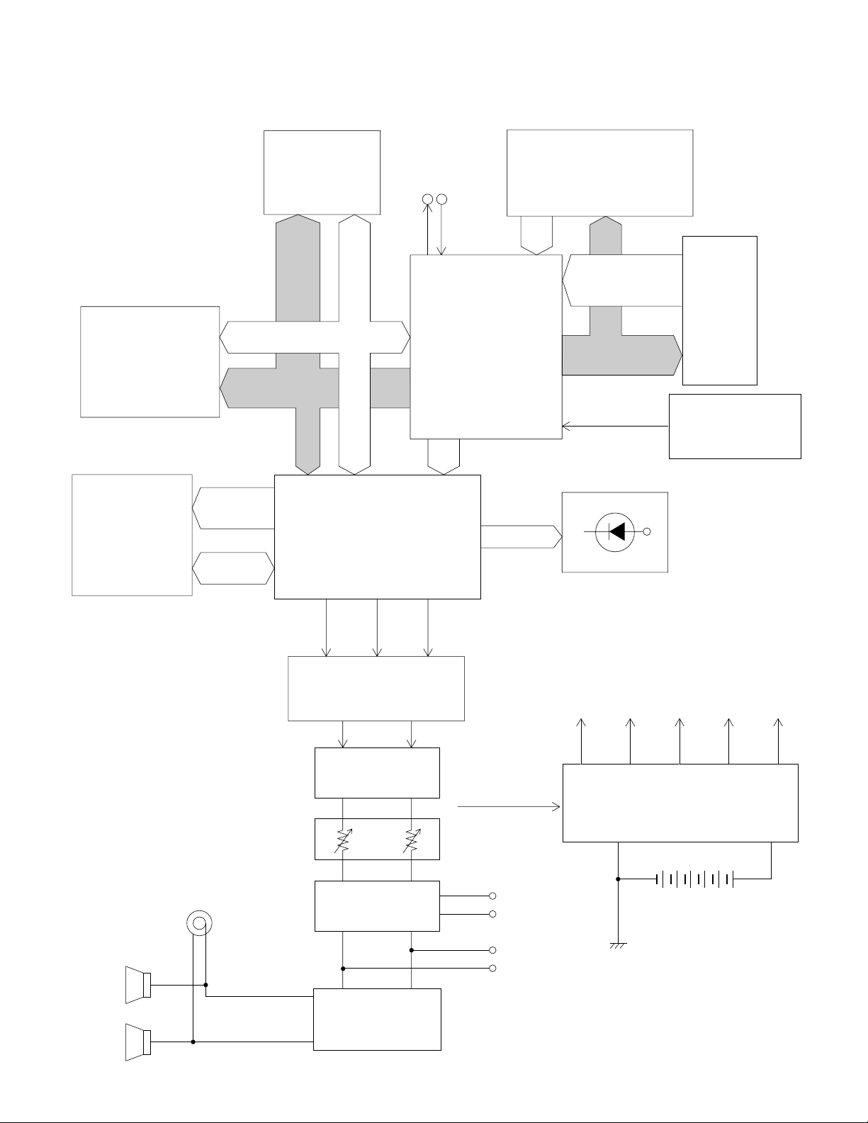
BLOCK DIAGRAM
Working Storage
RAM (64K-bit)
LSI2
HY6264ALLJ-70
MIDI
INOUT
Buttons
Sound Source ROM
(8M-bit)
LSI3
MX23C1610MC-12
Effect RAM
(256K-bit)
LSI5
TC55257DFL-70L
EA0 ~
EA14
EIO0 ~
EIO7
MA0
~
MA12
MD0 ~ MD15
MA1 ~ MA19
MD0
~
MD7
DSP
LSI1
HG51B277FB
LRCK SO
BCK
KI0 ~ KI2
CPU
LSI4
GT913F
BCK, SO, LRCKMA0, MA1
SONGA
SONGB
DIGITAL EFFECT
SELECT
STOP
FI0 ~ FI10
SI0 ~ SI10
Keyboard
KC0 ~ KC7
Reset IC
IC 1
RN5VD35AA
LEDs
VDD
Speakers
Output
D/A Converter
LSI6
UPD6379GR
Rmel Lmel
Filter
IC104
Main
Volume
Pre. Amp.
IC103
Power Amplifier
IC101
LA4620
— 3 —
POWER (APO)
From CPU
Line In
Line Out
AVCCVDD VCC AVDD LVDD
Power Supply Circuit
Q101 ~ Q106
D108, D110, D111
6 × D-size batteries
AC adaptor AD-12
Page 5
CIRCUIT DESCRIPTION
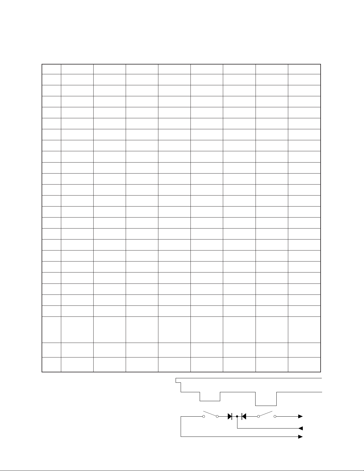
KEY MATRIX
0CK1CK2CK3CK4CK5CK6CK7CK
0IF)1(0A)1(0#A)1(0B)1(1C)1(1#C)1(1D)1(1#D)1(1E
0IS)2(0A)2(0#A)2(0B)2(1C)2(1#C)2(1D)2(1#D)2(1E
1IF)1(1F)1(1#F)1(1G)1(1#G)1(1A)1(1#A)1(1B)1(2C
1IS)2(1F)2(1#F)2(1G)2(1#G)2(1A)2(1#A)2(1B)2(2C
2IF)1(2#C)1(2D)1(2#D)1(2E)1(2F)1(2#F)1(2G)1(2#G
2IS)2(2#C)2(2D)2(2#D)2(2E)2(2F)2(2#F)2(2G)2(2#G
3IF)1(2A)1(2#A)1(2B)1(3C)1(3#C)1(3D)1(3#D)1(3E
3IS)2(2A)2(2#A)2(2B)2(3C)2(3#C)2(3D)2(3#D)2(3E
4IF)1(3F)1(3#F)1(3G)1(3#G)1(3A)1(3#A)1(3B)1(4C
4IS)2(3F)2(3#F)2(3G)2(3#G)2(3A)2(3#A)2(3B)2(4C
5IF)1(4#C)1(4D)1(4#D)1(4E)1(4F)1(4#F)1(4G)1(4#G
5IS)2(4#C)2(4D)2(4#D)2(4E)2(4F)2(4#F)2(4G)2(4#G
6IF)1(4A)1(4#A)1(4B)1(5C)1(5#C)1(5D)1(5#D)1(5E
6IS)2(4A)2(4#A)2(4B)2(5C)2(5#C)2(5D)2(5#D)2(5E
7IF)1(5F)1(5#F)1(5G)1(5#G)1(5A)1(5#A)1(5B)1(6C
7IS)2(5F)2(5#F)2(5G)2(5#G)2(5A)2(5#A)2(5B)2(6C
8IF)1(6#C)1(6D)1(6#D)1(6E)1(6F)1(6#F)1(6G)1(6#G
8IS)2(6#C)2(6D)2(6#D)2(6E)2(6F)2(6#F)2(6G)2(6#G
9IF)1(6A)1(6#A)1(6B)1(7C)1(7#C)1(7D)1(7#D)1(7E
9IS)2(6A)2(6#A)2(6B)2(7C)2(7#C)2(7D)2(7#D)2(7E
01IF)1(7F)1(7#F)1(7G)1(7#G)1(7A)1(7#A)1(7B)1(8C
01IS)2(7F)2(7#F)2(7G)2(7#G)2(7A)2(7#A)2(7B)2(8C
0IK
1IKDROCERLORTNOCOMED
2IKPOTSTRATS
LATIGID
TCEFFE
/1ONAIP
2ONAIP
/1ONAIP.E
2ONAIP.E
-OPSNART
GES
ENO
AES
-CISPRAH
/DROH
-HPARBIV
-OPSNART
#FES
-OPSNART
EPIP
/NAGRO
ZZAJ
NAGRO
-OPSNART
#GES
-OPSNART
BES
/SGNIRTS
HTNYS
SGNIRTS
-OPSNART
#AES
-OPSNART
#CES
DES
TCELES
-OPSNART
/AGNOS
BGNOS
-OPSNART
EES
Note: Each key has two contacts,
the first conatct (1) and second contact (2).
Second contact (2)
— 4 —
Key
First contact (1)
FI
KC
SI
Page 6
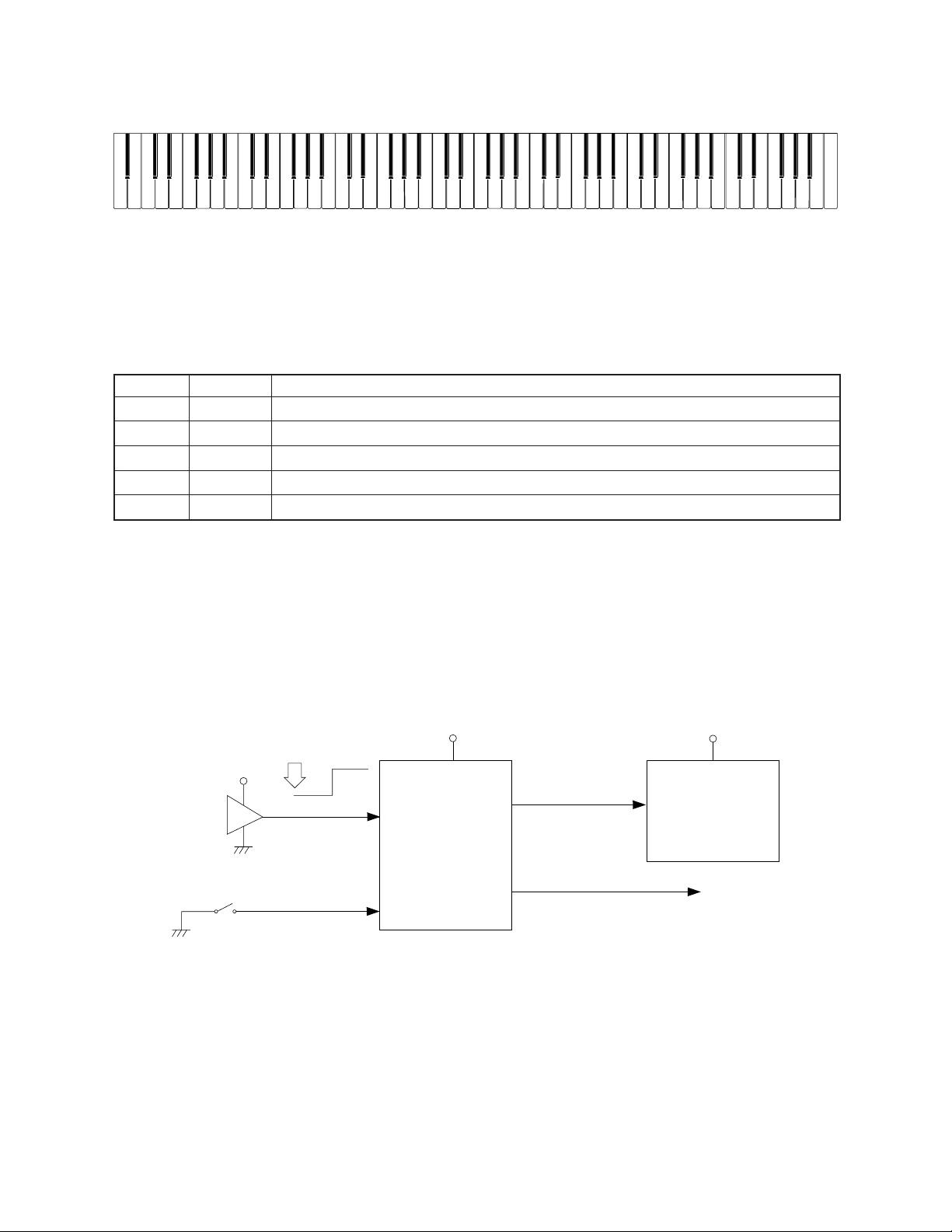
NOMENCLATURE OF KEYS
C#1 D#1 F#1G#1A#1
A#0
C#2 D#2 F#2 G#2A#2 C#3 D#3 F#3 G#3 A#3 C#4D#4 F#4 G#4 A#4 C#5 D#5 F#5 G#5 A#5 C#6 D#6 F#6 G#6 A#6 C#7 D#7 F#7 G#7 A#7
C2
D2 E2 F2 G2 A2 B2C1 D1 E1 F1 G1 A1 B1A0 B0 C3 D3 E3 F3 G3 A3 B3
C4 D4 E4 F4 G4 A4 B4 C5 D5 E5 F5 G5 A5 B5 D6 E6 F6 G6 A6 B6C6 C7 D7 E7 F7 G7 A7 B7 C8
POWER SUPPLY CIRCUIT
The power supply circuit generates five voltages as shown in the following table. VDD voltage is always
generated. The others are controlled by POWER signal from the CPU.
emaNegatloVfonoitareporoF
DDVV5+ MARtceffE,MARegarotsgnikroW,MORecruosdnuoS,PSD,CIteseR,UPC
DDVAV5+skcajnieniL,CAD
DDVLV5+pmaltoliP
CCVV9+reifilpmarewoP,skcajtuoeniL
CCVAV9+.pmAerP
RESET CIRCUIT
When batteries are set or an AC adapter is connected, the reset IC provides a low pulse to the CPU. The
CPU then initializes its internal circuit, and clears the working storage RAM.
When the power switch is pressed, the CPU receives a low level signal. The CPU sends POWER signal
to the power supply circuit, also sends a reset signal to the DSP.
When the keyboard is powered by batteries and no operation is made for six minutes, CPU drops signal
POWER to shut all the voltage except VDD off.
VDD
Power switch
Battery set
RESET
Reset IC
IC1
RN5VD35AA
NMI
CPU
LSI4
GT913F
VDD
Reset signal
PLE
HG51B277FB
POWER
SCKO
To power supply circuit
VDD
DSP
LSI1
— 5 —
Page 7
CPU (LSI4: GT913F)
The 16-bit CPU contains a 1k-byte RAM, three 8-bit I/O ports, two timers, a key controller and serial interfaces.
The CPU detects key velocity by counting the time between first-key input signal FI and second-key SI from
the keyboard. The CPU reads sound data and velocity data from the sound source ROM in accordance with
the selected tone; the CPU can read rhythm data simultaneously when a rhythm pattern is selected. Then the
CPU provides 16-bit serial sound data to the DSP. The CPU also controls MIDI input/output and stores
sequencer data into the working storage RAM.
The following table shows the pin functions of LSI4.
.oNniPlanimreTtuO/nInoitcnuF
10DXTtuOtuptuolangisIDIM
20DXRnItupnilangisIDIM
30KCStuOtuptuolangis)FFOrewoPotuA;OPA(REWOP
41DXT— .dnuorgotdetcennoC.desutoN
51DXRnItupnilangisNOrewoP
61KCStuOtuptuoeslupgnizinorhcnysZHM1
9~7
01DNGAnIecruos)V0(dnuorG
11KCBtuOtuptuokcolctiB
21OStuOtuptuoataddnuoslaireS
31KCRLtuOtuptuokcolcdroW
41DNGnIecruos)V0(dnuorG
61,511TLX,0TLXtuO/nItuptuo/tupnikcolczHM42
71CCVnIecruosV5+
91,811DOM,0DOMnI.dnuorgotdetcennoC.lanimretnoitcelesedoM
02BTSRnItupnilangisteseR
12IMNnItupnilangisNOrewoP
22TNI— dnuorgotdetcennoC
03~32
83~137CK~0CKtuOlangisnacsyekroflanimreT
25~93
55~352IK~0IKnIlangistupninottubroflanimreT
65BNWMtuOPSDehtroflangiselbaneetirW
67~7591AM~0AMtuOsubsserddA
770BSCMtuOMORecruosdnuosehtroftuptuolangiselbanepihC
871BSCMtuOdesutoN
972BSCMtuOPSDehtroftuptuolangiselbanepihC
08CCVnIecruosV5+
18DNGnIecruos)V0(dnuorG
28BDRMtuOMORecruosdnuosehtroftuptuolangiselbanedaeR
89~3851DM~0DMtuO/nIsubataD
99ELPnI
00171PnItupniladeP
,0NA,CCVA
1NA
3IF~0IF
3IS~0IS
01IF~4IF
01IS~4IS
—.dnuorgotdetcennoC.desutoN
nIlangistupniyekroflanimreT
nIlangistupniyekroflanimreT
.tiucricylppusrewopehtot
lanimreteht,rotpadaCAnaybderewopsidraobyekehtnehW
langisfforewopotuadnestonseodUPCehttahtostlov0semoceb
— 6 —
Page 8
DIGITAL SIGNAL PROCESSOR (LSI1: HG51B227FB)
The DSP receives 16-bit serial sound data from the CPU and adds the selected effect to the sound data using
the effect RAM. Then the DSP provides the sound data to the DAC. The DSP also drives LEDs.
The following table shows the pin functions of LSI1.
.oNniPlanimreTtuO/nI
08,4~14BP~0BP— .dnuorgotdetcennoC.desutoN
5OStuOCADehtroftuptuoataddnuoslaireS
6OKCWtuOCADehtroftuptuokcolcdroW
73DDVnIecruosV5+
8TSET—desutoN
9BSERnItupnilangisteseR
012SSVnIecruos)V0(dnuorG
21,11TUOX,NIXtuO/nItuptuo/tupnikcolczHM61
31IKCWnIUPCehtmorftupnikcolcdroW
41ISnIUPCehtmorftupniataddnuoslaireS
51IKCBnIUPCehtmorftupnikcolctiB
61CNISnItupnieslupgnizinorhcnyszHM1
712DDVnIecruosV5+
52~817OI~0OItuO/nIsubataD
62BECRtuOMARegarotsgnikrowehtroftuptuolangiselbanepihC
723SSVnIecruos)V0(dnuorG
821DAnIsubsserddA
92BEO— .dnuorgotdetcennoC.desutoN
03BEWnIlangiselbaneetirW
133DDVnIecruosV5+
232ECnI.evitcahgiH.tupnilangiselbanepihC
330DAnIsubsserddA
43B1ECnI.evitcawoL.tupnilangiselbanepihC
34,14~537OIE~0OIEtuO/nIMARtceffeehtrofsubataD
,84~64,44,24
16,95~15
54BECEtuOMARtceffeehtroftuptuolangiselbanepihC
94BEOEtuOMARtceffeehtroftuptuolangiselbanedaeR
053SSVnIecruos)V0(dnuorG
06BEWEtuOMARtceffeehtroftuptuolangiselbaneetirW
87,47,07,66,262SSVnIecruosdnuorG
97,57,17,76,362DDVnIecruosV5+
,96,86,56,46
37,27
77,677/6APtuOdesutoN
41AE~0AEtuOMARtceffeehtrofsubsserddA
5AP~0APtuOtuptuolangisnacsnottuB
noitcnuF
— 7 —
Page 9

DAC (IC1: UPD6379GR)
AVCC
Left
L
Right
From DAC
From DAC
To main volume
To main volume
R
AVCC
10 µF
10 µF
15 V10 µ
15 V10 µ
10 K
C472(H)
C472(H)
100 K
2.7 K
R154
100 K
C152(H)
C221B(A)
C152(H)
C221B(A)
2.2 K
10 K10 K
10 K10 K10 K
AGAG
M5218APR
(1/2) × 2
IC104
AG
AG
AG
AG
2
2
+
–
+
–
1
2
3
4
5
6
7
8
The DAC receives 16-bit serial data output from the DSP. The data contains digital sound data of the
melody, chord, bass, and percussion for the right and left channels. The DAC converts the data into
analog waveforms and output them to each channel separately.
Synch signal
L OUT
R OUT
DAC
LSI6
UPD6379GR
SI
Word clock
LRCK
CLK
Data
WCKO
Bit clock
SO
DSP
LSI1
HG51B277FB
SINC
SI
Word clock
WCKI
Bit clock
BCKI
Data
SCK1
SO
LRCK
BCK
CPU
LSI4
GT913F
FILTER BLOCK
Since the sound signals from the DAC are stepped waveforms, the filter block is added to smooth the
waveforms.
— 8 —
Page 10

POWER AMPLIFIER (IC101 : LA4620)
The power amplifier is a two-channel amplifier with standby switch.
IN11+
IN11–
IN12–
PriGND
IN21+
IN21–
IN22–
+
3
5
4
6
9
7
8
Input
Amp.
–
–
Input
Amp.
+
Terminal
Protection
Circuit
+
Input
Amp.
–
–
Input
Amp.
+
Pre-drive
Amp.
Pre-drive
Amp.
Pre-drive
Amp.
Pre-drive
Amp.
RL Short
Protector
Ripple
Filter
RL Short
Protector
16 2 10 11 13
NC DC MUTE ADJ
Power
Amp.
Power
Amp.
Power
Amp.
Power
Amp.
VCC2
Pop Noise
Prevention
Circuit
19
20
22
23
18
17
15
14
12
21
1
Boot11
OUT11
PoGND1
OUT12
Boot12
VCC1
Boot21
OUT21
PoGND2
OUT22
Boot22
— 9 —
Page 11

1
MAJOR WAVEFORMS
3
5
4
2
Power ON
1 ADP (POWER) signal
JE connector pin 5
2 NMI signal
JE connector pin 7
7
3 KC0 signal
JD connector pin 15
4 KC1 signal
JD connector pin 14
9
6
5 CE (MCSBO) signal
LSI3 pin 12
6 OE (MRDB) signal
LSI3 pin 14
8
7 DAC output (L-ch)
JE connector pin 12
8 DAC output (R-ch)
JE connector pin13
Tone : Strings
Key : A4
Reverb : ON
Volume : Maximum
Touch response : Maximum
0
9 Sound signal (L-ch)
JF connector pin 7
0 Sound signal (R-ch)
JF connector pin 8
— 11 —
Page 12

PRINTED CIRCUIT BOARDS
Main PCB JCM423-MA1M Sub PCBs JCM423-MA2M/MA3M/MA4M
8
7
2
1
3
4
Top View
6
5
Bottom View
Top View
9 10
— 12 —
Page 13

Main PCB JCM423-MA1M
SCHEMATIC DIAGRAMS
87
12
65
3
4
— 13 —
Page 14

Sub PCBs JCM423-MA2M/MA3M/MA4M
— 14 —
10
9
Page 15

Console PCBs JCM423-CN1M/CN2/CN3M
— 15 —
Page 16

Keyboard PCB JCM886T-KY1M
— 16 —
Page 17

Keyboard PCB JCM886T-KY2M
— 17 —
Page 18

Keyboard PCB JCM886T-KY3M
— 18 —
Page 19

27
EXPLODED VIEW
16
R-1
23
22
21
25
3
24
4
29
26
15
13
12
10
11
9
22
23
2
5
14
17
18
19
R-3
20
R-4
6
7
8
1
28
R-2
— 19 —
Page 20

SP-2
35
33
35
31
34
30
32
— 20 —
Page 21

PARTS LIST
CPS-85
Notes: This parts list does not include the cosmetic parts, which
parts are marked with item No. "R-X" in the exploded
view.
Contact our spare parts department if you need these
parts for refurbish.
1. Prices and specifications are subject to change without prior notice.
2. As for spare parts order and supply, refer to the
"GUIDEBOOK for Spare parts Supply", published
seperately.
3. The numbers in item column correspond to the same
numbers in drawing.
Page 22

Item Code No. Parts Name Specification Q R
Main PCB
1 6925 9150 PCB/ASSY (MA1M) M240661*1 1 A
LSI1 2012 4494 LSI,DSP HG51B277FB-1 1 A
LSI2 2012 1764 LSI/S-RAM LC3564SM-85-TRM 1 A
LSI3 2012 5669 LSI/MASK-ROM UPD23C16000WGX-C54 1 A
LSI4 2012 5005 LSI,CPU GT913F(T) 1 A
LSI5 2012 5572 LSI/S-RAM TC55257DFL-70L(EL) 1 A
LSI6 2105 4746 LSI/D/A CONVERTER UPD6379GR-E1 1 A
IC1 2105 6340 IC/MOS (RESET IC) RN5VD35AA-TR 1 B
Q1 2252 0637 TRANSISTOR 2SC4081-T106R 1 B
Q2 2250 1162 TRANSISTOR 2SA1576A-T106R 1 B
X1 2590 2387 OSCILLATOR/CRYSTAL HC-49/US24B 1 A
X2 2590 2079 OSCILLATOR/CERAMIC CSACS16.00MX040-TC 1 A
Sub PCB
2 6925 9180 PCB/ASSY (MA2,3,4M) M140596*1 1 B
IC101 2114 1883 IC/LINEAR LA4620 1 A
IC102 ~ 104 2114 1799 IC/LINEAR M5218APR 3 B
IC105 2252 1248 IC/PHOTO COUPLER HCPL-261A 1 B
Q101 2251 0672 TRANSISTOR 2SB1548-P.CS 1 A
Q102,Q104~106,
2220 1387 TRANSISTOR 2SC1740SQ-TP-T 7 A
Q109~111
Q103 2250 0168 TRANSISTOR 2SA854-SR-TP-T 1 A
Q107/108 2253 0420 TRANSISTOR 2SD1468SR.S-TP-T 2 A
D101/102 2390 1463 DIODE,SCHOTTKY SB20-03B 2 B
D102/103/107,
2390 1344 DIODE 1SS133T-77-T 5 B
D109/113
D104/105/D111 2360 1946 DIODE/ZENER MTZJ5.6CT-77-T 2 A
D108 2360 1085 DIODE/ZENER HZS6B1LTD-T 1 A
D110 2360 1939 DIODE/ZENER MTZJ5.1CT-77-T 1 A
J101 3501 5012 JACK/POWER HEC2305-01-920 1 A
J102/103, J106 3612 0789 JACK YKB21-5010 3 B
J104/105 3612 0584 JACK YKB21-5012 2 B
J107 3501 4816 JACK/DIN YKF51-5051 1 B
J108 3612 0665 JACK YKB21-5006 1 B
Console PCBs
3 6925 9190 PCB/ASSY (CN1,3M) M240662*1 1 B
D201 ~ 215 2390 1344 DIODE 1SS133T-77-T 15 B
LED201 ~ 207 2370 0630 LED LN282RPX-(TX3) 7 B
SW201 3412 1008 SWITCH/SLIDE SSB-22KP 1 B
SW202 ~ 214 3412 0903 SWITCH/TACT EVQ-21405R 13 B
VR201 2765 0952 POTENTIOMETER EWA-NAXCH1B23 1 A
4 6925 9200 PCB/ASSY (CN2) M440475*1 1 B
Keyboard unit
5 6906 8554 KEYBOARD UNIT M111412D*2 1 C
6 6925 9210 PCB/ASSY (KY1M) M140591*1 1 B
7 6925 9220 PCB/ASSY (KY2M) M240655*1 1 B
8 6925 9230 PCB/ASSY (KY3M) M140592*1 1 B
9 6921 6290 KEY/WHITE (BE) M311948*3 15 A
10 6921 6270 KEY/WHITE (CF) M311948*1 14 A
11 6921 6280 KEY/WHITE (D) M311948*2 7 A
12 6921 6300 KEY/WHITE (G) M311948*4 7 A
13 6921 6310 KEY/WHITE (A) M311948*5 7 A
14 6921 6320 KEY/WHITE (SA) M311948*6 1 B
15 6921 6330 KEY/WHITE (SC) M311948*7 1 B
Notes: Q – Quantity per unit
R – Rank
— 21 —
Page 23

Item Code No. Part Name Specification Q R
16 6921 6340 KEY/BLACK M311949*1 36 A
17 6921 4771 SPRING/KEY (W) M411982A-1 52 B
18 6906 6352 SPRING/KEY (B) M411983B-1 36 B
19 6915 8551 RUBBER/CONTACT M310664A-1 1 A
20 6915 8541 RUBBER/CONTACT M310663A-1 7 A
D701~876 2301 0101 DIODE 1S2473T-77-1 176 B
Cases
21 6919 3281 BUTTON M311398A-1 1 C
22 6919 3300 BUTTON M311398-2 2 C
23 6919 4530 BUTTON M311398-4 2 C
24 6919 3241 KNOB M311405-1 3 B
25 6909 5890 SWITCH/SLIDE KONB CSB-12D 1 B
26 3831 0686 SPEAKER KUS-14RGF01A 2 B
27 6906 8561 COVER/BATTERY M210564A-4 1 B
28 5530 0488 RUBBER/FOOT RK-24 7 C
29 6921 4590 CAP M412064-1 14 C
Accessories
6906 8513 STAND/NOTE M311787C*4 1 B
6921 4551 DUST COVER M311882A-1 1 B
SP-2 (pedal)
30 3421 0091 SWITCH/LEAF LSA-7FAU 1 B
31 3701 0035 PLUG CORD PM3249-2B 1 B
32 6908 3890 CASE ASSY/LOWER (SP2) M32349*1 1 C
33 6908 3901 CASE ASSY/UPPER (SP2) M32348A*1 1 C
34 6908 3910 SPRING M42928-1 1 C
35 6908 3921 SCREW M42929A-1 2 C
CS-81P(stand)
6922 6050 STAND CS-81P 1 C
1909 7840 SCREW SET S-CS-81P 1 C
Notes: Q – Quantity per unit
R – Rank
— 22 —
Page 24

MA0700571A
8-11-10, Nishi-Shinjuku
Shinjuku-ku, Tokyo 160, Japan
Telephone: 03-3347-4926
 Loading...