

Page 1
AP-22S
ELECTRONIC KEYBOARD
Page 2
CONTENTS
Safety Notice...................................................................................... 2
Specifications .................................................................................... 4
Block Diagram ................................................................................... 5
PCB Layout ........................................................................................ 6
Disassembly Instructions ................................................................. 7
Circuit Description .......................................................................... 11
Major Waveforms.............................................................................13
Printed Circuit Board ...................................................................... 14
Troubleshooting .............................................................................. 15
Wiring Diagram ................................................................................ 19
Exploded View ................................................................................. 20
Parts List .......................................................................................... 23
Schematic Diagrams .......................................................................25
SAFETY NOTICE
CAUTION!
Danger of explosion if battery is incorrectly replaced. Replace
only with the same or equivalent type.
— 2 —
Page 3
DENMARK:
FINLAND:
ADVARSE!
Lithiumbatteri. Eksplosionsfare ved fejlagtig handtering.
Udskiftning ma kun ske med batteri af samme fabrikat og type.
Lever det brugte batteri tilbage tili leverandoren.
SWEDEN:
VAROITUS
Paristo voiäjähtää, jos se on virheellisesti asennettu. Vaihda
paristo ainoastaan valmistajan suosittelemaan tyyppiin. Hävitä
käytetty paristo valmistajan ohjeiden mukaisesti.
VARNING
Felaktigt batteribyte kan medf fara för explosion. Använd därför endast samma typ eller likvärdig typ enligt apparattillverkarens rekommendation.
Kassera förbrukade batterier enligt tillverkarens anvisning.
— 3 —
Page 4

SPECIFICATIONS
GENERAL
Keyboard: 88 piano keys (with touch response)
Polyphony: 32 notes, maximum
Tones: • 10 (including two bass tones)
• Tuning Curves: 3 (preset for each tone)
• Layer: Adjustable volume
• Split: Split point, adjustable volume
Digital Effects: Reverb (4 types), Chorus, Tremolo, Brilliance
Demo Tunes: • Number of Tunes: 8
• Playback: Repeat (all tunes, one tune)
Memory: • Operations: Real-time recording, playback
• Number of Tracks: 2 (Track A, Track B)
• Capacity: Approximately 5,000 notes (total of 2 tracks)
• Memory Backup: Built-in lithium battery (Battery Life: 5 years)
Song Lesson: • Number of Tunes: 80
• Playback: All song repeat, specific song
• Part Off: L, R
• Phrase Repeat
Pedals: Damper, Soft, Sostenuto
Other Functions: • Metronome: Beat (6 types), Tempo (q = 30 to 300)
• Touch Select: 3types
• Transpose: 1 octave (F# to C TO F)
• Tuning: A4 + 440 Hz ±13 Hz (adjustable)
• Temperament: 7 types
• Baroque pitch
MIDI: 16 multi-timbre receive
Input/Output: • Headphones: Standard stereo jacks × 2
• LINE OUT (R)(L): Standard stereo jacks × 2
Output impedance 22 KΩ
Output voltage: 2.0 V (RMS) MAX
• LINE IN (R)(L): Standard stereo jacks × 2
Input impedance: 30 KΩ
Input voltage 200 mV
• MIDI (OUT)(IN)
Speakers: ø 16 cm × 2, ø 5 cm x 2 (Output: 30 W + 30 W)
Power Supply: 120 V (for U.S.A.), 120 V, 220 V, 230 V and 240 V (for other countries) AC
household current via AC power cord supplied with piano.
Power Consumption: 70 W (with 120 V AC), 90 W (with 220 V, 230 V and 240 AC)
Dimensions: • CELVIANO Only: 139 × 54 × 25 cm (5.5 × 2.1 × 1.0 inch)
• CELVIANO and Stand: 139 × 54 × 88 cm (5.5 × 2.1 × 3.5 inch)
Weight: • CELVIANO Only: approximately 48.5 kg (106.9 lbs)
• CELVIANO and Stand: approximately 60.2 kg (132.7 lbs)
Accessories: Stand with three pedals, score book, power cord
— 4 —
Page 5
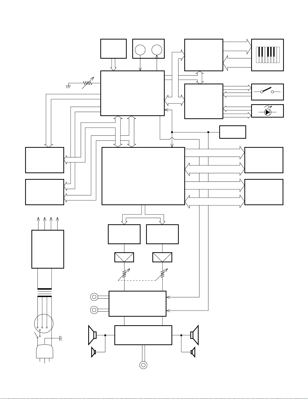
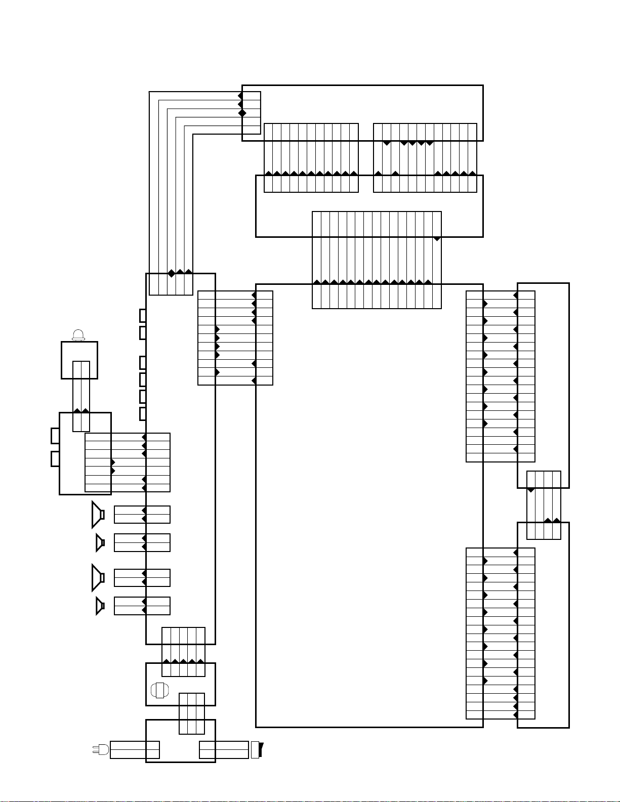
BLOCK DIAGRAM
A0 ~ 19
RAM
256K
TC55257DFL-
70L
ROM
8M
MX23C8000MC-
12CA73
PB4 ~ 6
BRILLIANCE
A0 ~ 14
D0 ~ 7
D0 ~ 7
PEDAL
CPU
HD6435328RF35F
HG51B155FD
MIDI
IN
OUT
M-IN M-OUT
DSP
P70 ~
P77
MUTE
Keyboard
Controller
HG52E35P
P12 ~
P14
Switch & LED
Controller
µPD65005GF-419
RST
RA0 ~ 22
RD0 ~ 15
EA0 ~ 14
ED0 ~ 15
KC0 ~ 7
FI0 ~ 10
SI0 ~ 10
L18 ~ 28
KI0 ~ 3
LA ~ LG, LP
LK8 ~ 14
Reset IC
MB3771PF
Keyboard
Buttons
LEDs
ROM
24M
MX23C2410MC-
12CA58
RAM
256K × 2
TC55257DFL-
70L × 2
AVCC
AVDD
AVFF
+15V
+5V
–15V
+5V
NJM78L05A
NJM7805FA
NJM78M78M15FA
T101
Power Switch
VDD
Power
Transformer
Voltage
selector
LINE OUT
LINE IN
SOLM, SOLP
D/A Converter
µPD6376GS
Filter
Main
Volume
Mixer, Mute Circuit
BDK, WOK1, SORM, SORP
D/A Converter
µPD6376GS
Filter
SPSP
Power Amp.
STK4132MK
Tweeter Tweeter
HEADPHONE
— 5 —
Page 6
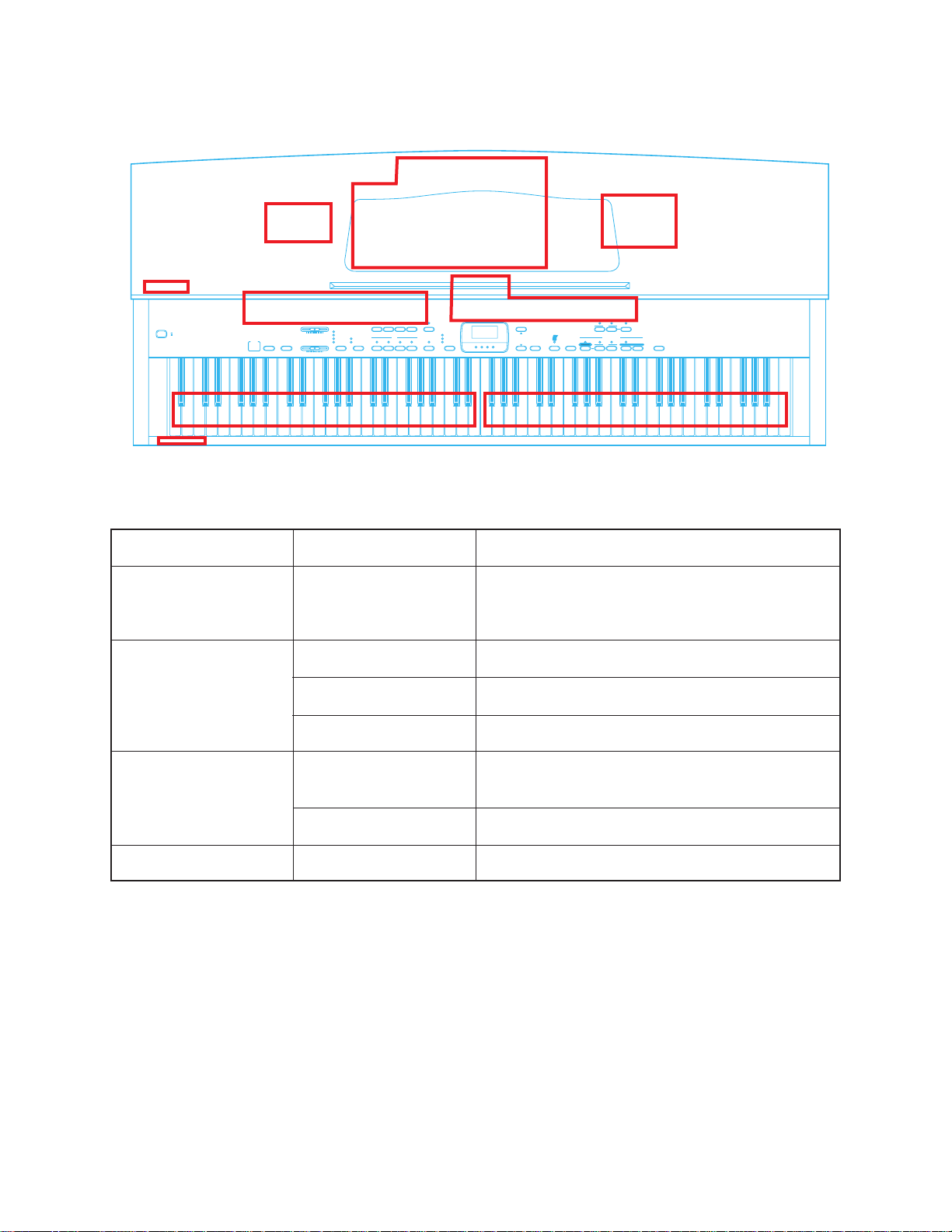
PCB LAYOUT
PS3M
POWER
ONON
OFFOFF
PS4M
Main PCB
Jack PCBs
PCB
PS11
CONTROLCONTROL MIDIMIDI
MELLOWMELLOW BRIGHTBRIGHT
E
TRANSPOSETRANSPOSE
E
TUNETUNE
E
MIDIMIDI
E
BRILLIANCEBRILLIANCE
E
METRONOME VOL
CONTROLCONTROL
TP20-KY1M
MA1M
PS2M
CN2M
BRILLIANCE
ROOMROOM
STAGESTAGE
HALL 1HALL 1
HALL2HALL2
VOLUME
MIN
MAXMAX
MIN
PIANO 1PIANO 1 PIANO 2PIANO 2 E.PIANO
TONE
TONE
CHORUSCHORUS
TREMOLOTREMOLO
PIPE ORGAN
STRINGS
VIBRAHONE
PIPE ORGAN
STRINGS
VIBRAHONE
CHORUS/TREMOLOCHORUS/TREMOLO
JCM434-
HARPSICHORD
CHOIR
CHOIR
PS2M
W. BASS
W. BASS
LIGHT
LOWER TONE
LOWER TONE
MIDDLE
HEAVY
E. BASS
TOUCH SELECT
E. BASS
TOUCH SELECT
MA1M
CN1M
MALTI FUNCTION DISPLAYMALTI FUNCTION DISPLAY
VALUE
TEMPO/BEAT/
FIXED
TRACK
RECORD
TRACK
RECORD
A B
SONG LESSON/MEMORY
SONG LESSON/MEMORY
PLAY/STOP
PART
SONG
PLAY/STOP
PART
LLR
DEMO
DEMO
PHRASE REPEATPHRASE REPEAT NEXTMETRONOMEREVERB
R
TP20-KY2M
Components
CPU, DSP, Sound Source ROM Working storage
RAM, Effect RAM Reset IC, DAC, Filter, Key controller, Power amp, Power supply circuit
LINE IN/OUT jack, MIDI jacks
Console PCBs
Power PCB
PS3M
PS4M
CN1M
CN2M
PS11
Phone jacks
Power indicator
Gate array (Button controller/LED driver), LEDs,
Buttons
Main Volume, Brilliance volume, LEDS, Buttons
Fuse, Noise filter
— 6 —
Page 7
DISASSEMBLY INSTRUCTIONS
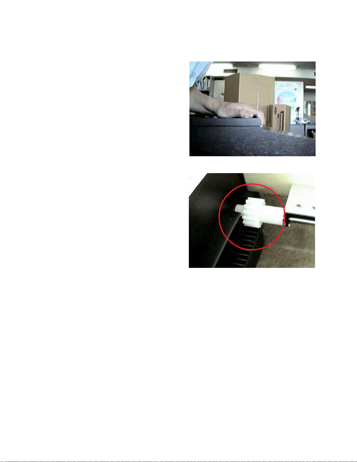
1. Disassembling top board
1-1. Remove 8 screws on the rear.
1-2. Slide the top board towards the rear.
The top board will be free from catches on the
case.
1-3. Lift the top board.
2. Disassembling keyboard cover
2-1. Slide the keyboard cover to open fully.
2-2. Passing the gear into the opening on each
rack, lift the keyboard cover.
— 7 —
Page 8
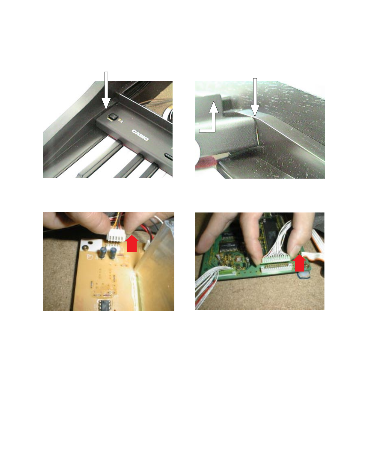
3. Disassembling console panel
Note: To avoid scratch on the side board, put paper between the console panel and the side board at
both ends.
Insert paper here.
Insert paper here.
3-1. Remove three screws afixing the console panel.
3-2. Remove the screw fixing a grounding wire at the transformer.
3-3. Disconnect two connectors CF on PCB JCM434-PS2M and CD on PCB JCM434-MA1M
3-4. Slide the console panel towards the front to free from catches.
3-5. Turn round the console panel.
3-6. Remove the 2 screws fixing the power switch.
— 8 —
Page 9
4. Disassembling front cover
4-1. Remove 9 screws at the front edge on the bottom.
4-2. Unscrew 2 screws and remove JCM434-PS4M
5. Disassembling keyboard unit
5-1. Remove 12 screws fixing front end of the keyboard unit and three screws supporting rear end of
the keyboard.
5-2. Remove 2 connectors CA and CB on PCB JCM434-MA1M.
5-3. Lift up the keyboard unit.
— 9 —
Page 10
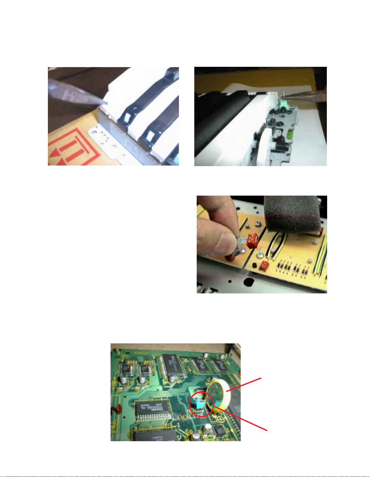
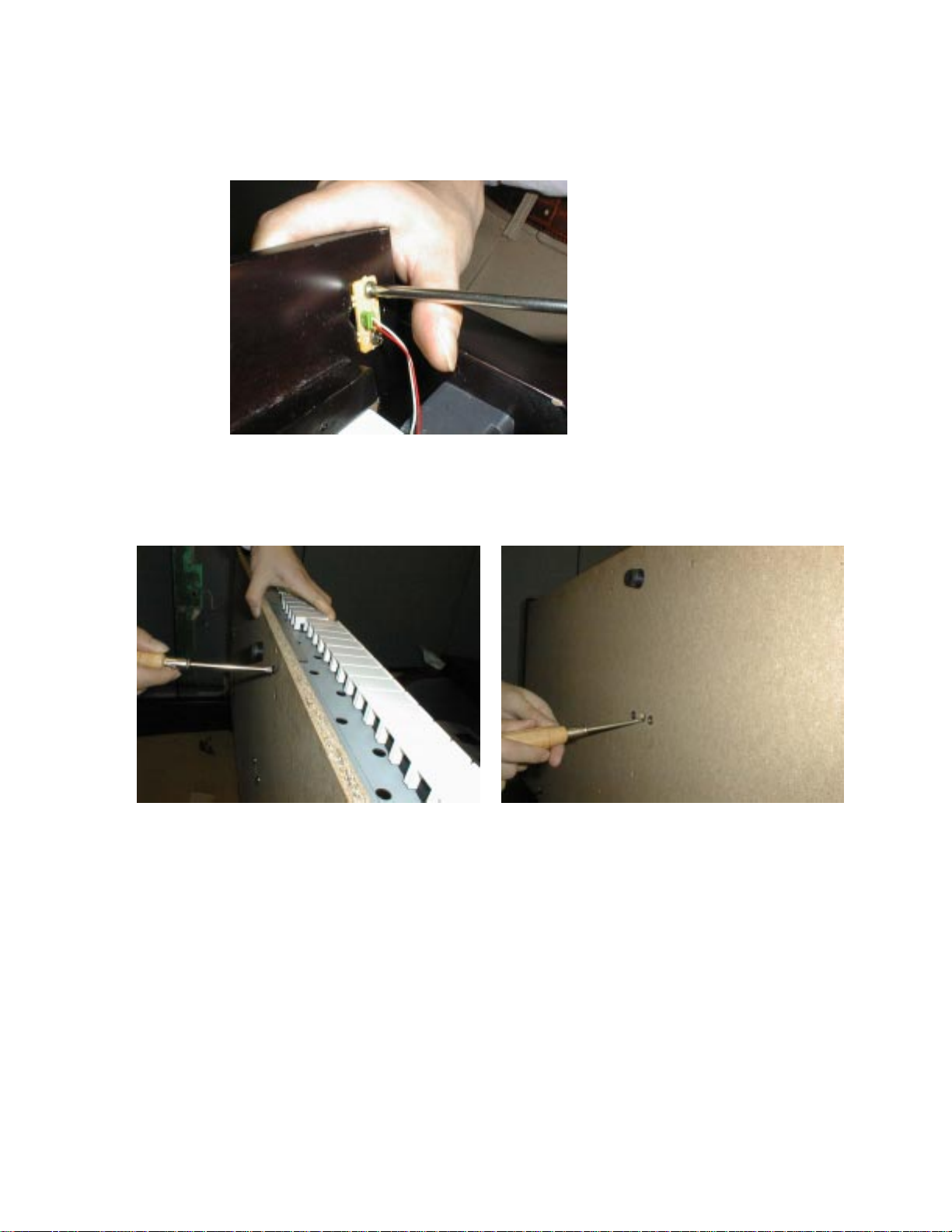
6. Disassembling keys
6-1. Pressing the hook with long-nose pliers, lift the key.
6-2. Using pliers, remove key spring.
7. Disassembling keyboard PCBs
7-1. Turn round the keyboard unit to face the PCB
up.
7-2. Disconnect the connector at the middle of
keyboard.
7-3. Remove screws on the keyboard PCBs.
8. Replacing the main PCB
Note: The main PCB contains a lithium battery for memory back-up. Please remove the jumper
before replacing the PCB. And make sure that the jumper is reset on new main PCB after
replacing the PCB. Because no jumper is set on a spare part of the main PCB.
Lithium battery
Jumper
— 10 —
Page 11

KEYMATRIX
CIRCUIT DESCRIPTION
Second contact First contact
FI
KC
SI
KC0 KC1 KC2 KC3 KC4 KC5 KC6 KC7
FI0 A0 1 A0 # 1 B0 1 C1 1 C1 # 1 D1 1 D1 # 1 E1 1
SI0 A0 2 A0 # 2 B0 2 C1 2 C1 # 2 D1 2 D1 # 2 E1 2
EI1 F1 1 F1 # 1 G1 1 G1 # 1 A1 1 A1 # 1 B1 1 C2 1
SI1 F1 2 F1 # 2 G1 2 G1 # 2 A1 2 A1 # 2 B1 2 C2 2
FI2 C2 # 1 D2 1 D2 # 1 E2 1 F2 1 F2 # 1 G2 1 G2 # 1
SI2 C2 # 2 D2 2 D2 # 2 E2 2 F2 2 F2 # 2 G2 2 G2 # 2
FI3 A2 1 A2 # 1 B2 1 C3 1 C3 # 1 D3 1 D3 # 1 E3 1
SI3 A2 2 A2 # 2 B2 2 C3 2 C3 # 2 D3 2 D3 # 2 E3 2
FI4 F3 1 F3 # 1 G3 1 G3 # 1 A3 1 A3 # 1 B3 1 C4 1
SI4 F3 2 F3 # 2 G3 2 G3 # 2 A3 2 A3 # 2 B3 2 C4 2
LSI
HG52E35P
FI5 C4 # 1 D4 1 D4 # 1 E4 1 F4 1 F4 # 1 G4 1 G4 # 1
SI5 C4 # 2 D4 2 D4 # 2 E4 2 F4 2 F4 # 2 G4 2 G4 # 2
FI6 A4 1 A4 # 1 B4 1 C5 1 C5 # 1 D5 1 D5 # 1 E5 1
SI6 A4 2 A4 # 2 B4 2 C5 2 C5 # 2 D5 2 D5 # 2 E5 2
FI7 F5 1 F5 # 1 G5 1 G5 # 1 A5 1 A5 # 1 B5 1 C6 1
SI7 F5 2 F5 # 2 G5 2 G5 # 2 A5 2 A5 # 2 B5 2 C6 2
FI8 C6 # 1 D6 1 D6 # 1 E6 1 F6 1 F6 # 1 G6 1 G6 # 1
SI8 C6 # 2 D6 2 D6 # 2 E6 2 F6 2 F6 # 2 G6 2 G6 # 2
FI9 A6 1 A6 # 1 B6 1 C7 1 C7 # 1 D7 1 D7 # 1 E7 1
SI9 A6 2 A6 # 2 B6 2 C7 2 C7 # 2 D7 2 D7 # 2 E7 2
FI10 F7 1 F7 # 1 G7 1 G7 # 1 A7 1 A7 # 1 B7 1 C8 1
SI10 F7 2 F7 # 2 G7 2 G7 # 2 A7 2 A7 # 2 B7 2 C8 2
— 11 —
Page 12

BUTTON MATRIX
KI0 KI1 KI2 KI3
L18 STEP BY STEP P ART L PART R NEXT
L19 TOUCH SELECT TRACK A TRACK B PLAY/STOP
L20 METRONOME
L24 PIANO 2 E. PIANO HARPSICHORD W.BASS
L25 PIANO 1 STRINGS CHOIR E.BASS
L26 VIBRAPHONE PIPEORGAN REVERB
L27 SONG SELECT RECORD
L28 VALUE DOWN VALUE UP DEMO
TEMPO/
BEAT/FIXED
CHORUS/
TREMOLO
POWER SUPPLY CIRCUIT
The power supply circuit generates four voltages as shown in the following table.
Name Voltage For operation of
VDD +5 V CPU, Reset IC, Working storage RAM, DSP, Key touch LSI, Sound
source ROM, Effect RAM, Gate array
AVDD +5 V DAC
A VCC +15 V Filter, Mixer
AVFF –15 V Filter, Mixer
— 12 —
Page 13

MAJOR WAVEFORMS
A 1ms
1
2
˜˜
CH1 .2V CH2 .2V
1 Filter output L-ch CF connector pin 4
2 Filter output R-ch CF connector pin 5
Tone : Piano 1
Key : A4
A 2ms
6
CH1
CH2
CH1
A 20 µs
3
4
5
˜
CH1 5V CH2 5V
CH3 5V
3 Key scan signal KC0 CB connector pin 2
4 Key scan signal KC1 CB connector pin 4
5 Key scan signal KC2 CB connector pin 6
CH1
CH2
CH3
7
8
CH1 5V CH2 5V
CH2 5V
6 Button scan signal L24 UPD65005GF-419 pin 53
7 Button scan signal L25 UPD65005GF-419 pin 54
8 Button scan signal L26 UPD65005GF-419 pin 55
CH2
CH3
— 13 —
Page 14

PRINTED CIRCUIT BOARD
C93
C95
C94
C96
C97
C98
C85
C86
C87
C88
C89
C83
C90
Top View
Bottom View
— 14 —
Page 15

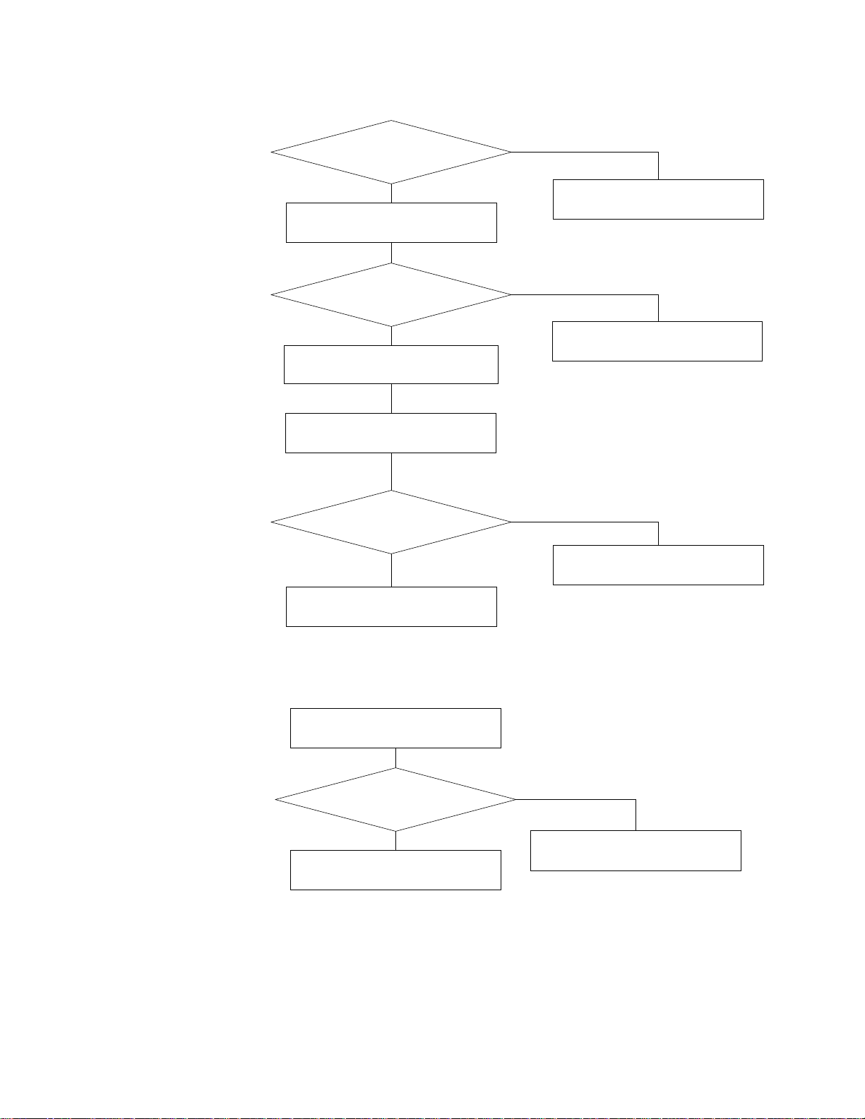
1. No power
TROUBLESHOOTING
Check fuse F101.
Yes
Is F101 blown up?
No
Check fuses F402, F403, and F404.
Are the fuses blown up?
No
Measure output voltages of
the transformer.
Yes
Replace main PCB. No
Are the voltages 40 V AC
and 8 V AC?
Check the power switch.
Is it OK?
Replace F401.
Yes
Replace F402, F403, and F404.
No
Yes
Check position of voltage
selector.
Is it OK?
Yes
Replace the transformer.
— 15 —
Replace the power switch.
No
Set the voltage selector at
proper position.
Page 16
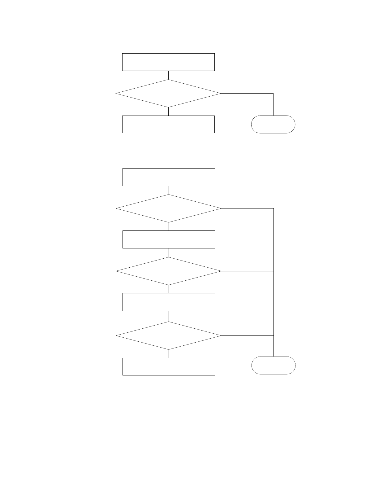
2. No sound
Does the power indicator
light up?
Yes
Check the main volume.
Is it OK?
Yes
Disconnect CA and CB
connectors on the main PCB.
Press Demo button.
Does the demo tune sound?
No
Follow "No power"
troubleshooting.
No
Replace main volume.
No
3. Distorted sound
Yes
Replace keyboard PCBs.
Check the voltage selector.
Is it at proper position?
Yes
Replace the main PCB.
Replace the main PCB.
No
Set the voltage selector at
proper position.
— 16 —
Page 17
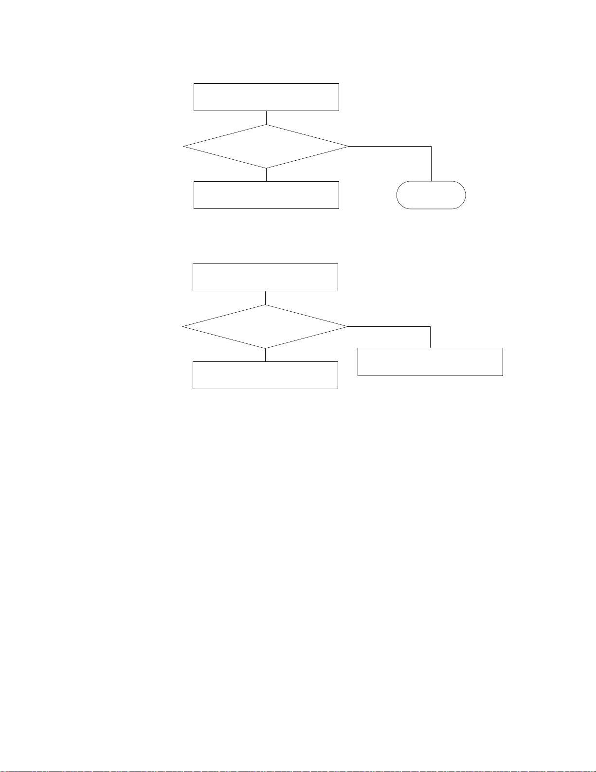
4. Certain keys do not function
Replace the main PCB.
Do the keys function?
Replace keyboard PCBs.
5. A certain key does not function
Clean the contact.
Does the key function?
Replace the key contact rubber.
Does the key function?
Yes
No
End
Yes
No
Yes
No
Replace keyboard PCBs.
Does the key function?
No
Replace the main PCB.
Yes
End
— 17 —
Page 18
6. A certain button does not function
Replace the console PCBs.
Does the button function?
Yes
No
Replace MA1M PCB.
7. A certain tone is strange when record/playback
Check the cord of pedal unit
Yes
Is it disconnected?
No
Replace the main PCB.
End
Connect the cord
— 18 —
Page 19
WIRING DIAGRAM
POWER Lamp
JCM434
-PS4M
CH-1
CH-2
LVD
DG
CH-1
CH-2
CG-1
CG-2
PHONE
CG-3
CG-4
CG-5
CG-6
CG-7
JCM434-PS3M
POWER
TRANSFORMER
AC PLUG
LINE OUT MIDI
LINE IN
LVD
DG
AG
LSP
RSP
R-HP
L-HP
RSP+
RSP–
RT+
RT–
LSP+
LSP–
LT+
LT–
AG
L-mel IN
R-mel IN
CF-1
CF-2
CF-3
OUT
JCM434-PS2M
RLRL IN
CG-1
CG-2
CG-3
CG-4
CG-5
CG-6
CG-7
CR-BK
CR-R
CN-W
CN-BK
CL-R
CL-BK
CM-W
CM-BK
OOWWBK
S4
S3
OOWWBK
JCM434
W
-PS11
R
R-mel IN
L-mel IN
AG
L-mel OUT
R-mel OUT
L-mel OUT
R-mel OUT
CF-4
CF-5
CC-1
CC-2
CC-3
CC-4
CC-5
CC-6
CC-7
CC-8
CC-9
CC-10
CC-11
2
C
S
S1
PPYBR
PPYBR
BL
GY
R-mel1
R-mel2
L-mel1
L-mel2
AG
AVDD
VDD
DG
MUTE
M-IN
M-OUT
CF-R
BR
E
O
Y
CC-1
CC-2
CC-3
CC-4
CC-5
CC-6
CC-7
CC-8
CC-9
CC-10
CC-11
JK-1
JK-2
JK-3
LK14
LK13
LK12
JK-1
JK-2
JK-3
POWER
Switch
JK-4
JK-5
JK-6
JK-7
JK-8
LgLfLe
JK-5
JK-6
CD-1
DG
CD-1
LdLcLb
JK-7
JK-8
CD-2
VDD
CD-2
CD-3
RESET
CD-3
LK11
JK-4
JCM434-MA1M
JCM434-CN2M
JK-9
JK-10
JK-11
JJ-1
JJ-2
JK-9
La
JK-10
JK-11
DGT
JJ-1
PB7
JJ-2
JCM434-CN1M
CD-4
CD-5
CD-6
CD-7
CD-8
CD-9
P93
P94
P90
P14
P13
P12
CD-4
CD-5
CD-6
CD-7
CD-8
CD-9
JJ-3
JJ-4
KI3
VDDT
JJ-3
JJ-4
CD-10
CD-11
P73
P72
CD-10
CD-11
JJ-5
JJ-6
KI2
KI1
JJ-5
JJ-6
CD-12
CD-13
P71
P70
CD-12
CD-13
JJ-7
JJ-8
KI0
L26
JJ-7
JJ-8
CD-14
CD-15
VDDT
PB7
CD-14
CD-15
JJ-9
L25
JJ-9
JJ-10
JJ-11
L24
JJ-10
JJ-11
JJ-12
L20
L19
JJ-12
CA-1
CA-2
CA-3
CA-4
CA-5
CA-6
CA-7
CA-8
CA-9
CA-10
CA-11
CA-12
CA-13
CA-14
CA-15
CA-16
CA-17
CA-18
CA-19
CA-20
CB-1
CB-2
CB-3
CB-4
CB-5
CB-6
CB-7
CB-8
CB-9
CB-10
CB-11
CB-12
CB-13
CB-14
CB-15
CB-16
CB-17
CB-18
CB-19
CB-20
SI0
KC0
FI0
KC1
SI1
KC2
FI1
KC3
SI2
KC4
FI2
KC5
SI3
KC6
FI3
KC7
SI4
NC
FI4
NC
SI5
KC0
FI5
KC1
SI6
KC2
FI6
KC3
SI7
KC4
FI7
KC5
SI8
KC6
FI8
KC7
SI9
FI10
FI9
SI10
CA-1
CA-2
CA-3
CA-4
CA-5
CA-6
CA-7
CA-8
CA-9
CA-10
CA-11
CA-12
CA-13
CA-14
CA-15
CA-16
CA-17
CA-18
CA-19
CA-20
CB-1
CB-2
CB-3
CB-4
CB-5
CB-6
CB-7
CB-8
CB-9
CB-10
CB-11
CB-12
CB-13
CB-14
CB-15
CB-16
CB-17
CB-18
CB-19
CB-20
TP-20
KY1
123
NC
KC7
123
TP-20
KY2
FI4
4
SI4
4
— 19 —
Page 20
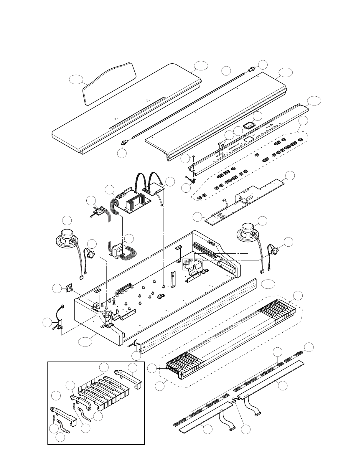
EXPLODED VIEW
CABINET
8
R-4
31
33
R-2
R-5
26
2
8
R-3
33
4
5
27
1
29
3
32
28
30
9
10
6
R-1
16
17
18
11
19
R-6
7
18
12
9
19
24
23
21
15
13
15
14
— 20 —
20
22
Page 21
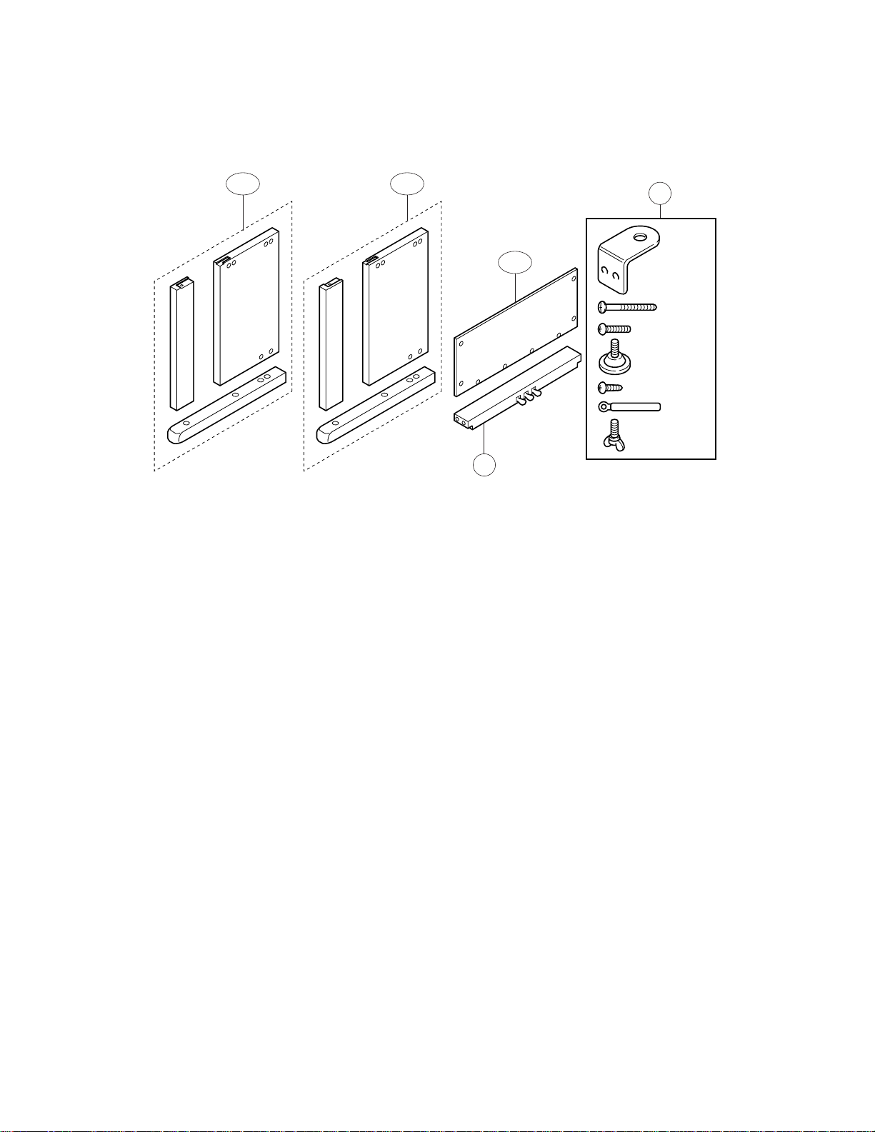
STAND
R-8R-7
R-9
34
35
— 21 —
Page 22

PARTS LIST
AP-22S
Notes: This parts list does not include the cosmetic parts, which
parts are marked with item No. "R-X" in the exploded
view.
Contact our spare parts department if you need these
parts for refurbish.
1. Prices and specifications are subject to change without prior notice.
2. As for spare parts order and supply, refer to the
"GUIDEBOOK for Spare parts Supply", published
seperately.
3. The numbers in item column correspond to the same
numbers in drawing.
Page 23
Item Code No. Parts Name Specification Q R
Main PCB
BT1 3815 0794 BATTERY/LITHIUM CR2032/1VC1 1 B
D1 - D5 2390 2555 DIODE/SHOTTKY RB500V-40TE-17 5 B
D6 2360 3057 DIODE/ZENER UDZTE-173.3B 1 A
IC1 2105 1120 IC/MOS TC7S08F-TE85R 1 B
IC2 2105 6354 IC/MOS TC74HC27AF(TP1) 1 B
IC3 2105 6353 IC/MOS TC74HC11AF(TP1) 1 B
IC4 2105 6355 IC/MOS TC7S00F(TE85R) 1 B
IC5 2114 4060 IC MB3771PF-EF 1 B
LSI1 2012 5844 LSI HD6435328RF35F 1 A
LSI10 2011 5194 LSI/KEY CONTROLLER HG52E35P 1 A
LSI2 2012 5843 LSI MX23C8000MC-12CA73 1 A
LSI3/8/9 2012 5572 LSI/RAM TC55257DFL-70L(EL) 3 A
LSI4/5 2114 4221 LSI/DAC UPD6376GS-E1 2 A
LSI6 2012 5707 LSI MX23C2410MC-12CA58 1 A
LSI7 2012 1316 LSI/DSP HG51B155FD-1 1 A
Q1 - Q3 2250 1162 TRANSISTOR 2SA1576AT106R 3 A
Q4 2252 0637 TRANSISTOR 2SC4081T106R 1 A
SNF1 3025 1505 CHIP EMI FILTER NFM51R00P106 1 B
X1 2590 2100 OSCILLATOR/CERAMIC CSACS20.00MX040-TC 1 B
X2 2590 2709 OSCILLATOR/CERAMIC HC-49US16384 1 B
1 6926 1980 M434-MA1M PCB ASSY M140657*1 1 A
Console PCBs
LED306 - LED332 2370 0630 LED LN282RPX-(TX3) 27 B
LED302 2370 1386 LED LN282RPX(V)-(TX2) 1 B
LED303 - LED305 2370 0679 LED LN382GPX-(TX2) 3 B
LED301 2370 0497 LED LB-603VP 1 B
IC301 2114 3318 IC BA612 1 B
LSI301 2011 0812 LSI UPD65005GF-419 1 A
Q309 - Q312 2220 1409 TRANSISTOR 2SC1740SR-TP-T 4 A
Q301 - Q308 2259 1883 TRANSISTOR DTA114TS-TP-T 8 A
SW301 - SW329 3412 0903 SWITCH/TACT EVQ-21405R 29 A
VR301 2765 0280 POTENTIOMETER EWA-NAXCH1B14 1 A
VR302 2765 2187 POTENTIOMETER EWA-NFECH1B54 1 A
2 6926 2060 M434-CN1M PCB ASSY M140658*1 1 A
2 6926 2070 M434-CN2M PCB ASSY M140659*1 1 A
Power supply PCBs
D405 - D408 2390 3022 DIODE 3BZ41(LC6-15) 4 B
D416 2390 1323 DIODE RB100A-T32-T 1 B
D422/423 2360 1729 DIODE MTZJ5.1AT-77-T 2 B
F402 3632 0273
F402
F403/406
F403/406
IC401 2114 5794 IC NJM78M15FA 1 B
IC402 2114 5795 IC NJM79M15FA 1 B
IC403 2114 5797 IC NJM78L05A(T3) 1 B
IC404 2114 3444 IC NJM7805FA 1 B
IC405 2114 2149 IC STK4152MK2 1 B
IC406/408/410/411 2114 1799 IC M5218APR 4 B
IC409 2252 1248 IC/PHOTO COUPLER HCPL-261A 1 B
J401/402 3612 0584 JACK YKB21-5012 2 A
J403/404 3612 0789 JACK YKB21-5010 2 A
J405 3501 4816 JACK/DIN YKF51-5051 1 B
Q401 - Q404 2254 0551 FET 2SK365-BL(TPE4) 4 A
3631 1045
3632 0420
3632 0427
Notes: Q – Quantity per unit
FUSE/TIME-LAG (US,CANADA)
FUSE/TIME-LAG (OTHERS)
FUSE/TIME-LAG (US,CANADA)
FUSE/TIME-LAG (OTHERS)
R – Rank
— 23 —
UL-TSC-1.6A-N1 1 A
(S)T-1.6A 1 A
UL-TSC-6.3A-N1 2 A
(S)T-6.3A 2 A
Page 24
Item Code No. Part Name Specification Q R
4 6926 5800 M434-PS2M PCB ASSY
(US,CANADA,DIRECT 110 - 127V AREA)
4
PS11, PS3, PS4 PCBs
J406 3613 1533 JACK HLJ4336-01-3040 1 A
F401 3632 0720
F401 3631 1045
L401 3013 2577 COIL/CHOKE PLAC1522R0R01B1 1 B
LED401 2320 9748 LED LN28RPH 1 B
SW402 3613 1740 VOLTAGE SELECTOR HXW1219-01-110 1 B
5 6926 2160
5
6 6926 2030 M434-PS3M PCB ASSY M340697*1 1 A
7 6926 2290 M434-PS4M PCB ASSY M340698*1 1 A
Other electrical parts
8 3831 1077 SPEAKER SG16G51BFA 2 B
9 3831 1075 SPEAKER/TWEETER S05JH37A 2 B
10
11 3012 1593 TRANSFORMER TE-434-1M1 1 B
12 6926 0370 KEYBOARD UNIT 88TP/20CASIO 1 B
13 6926 4890 HAMMER/WHITE KEY 88TP/20(42366750) 52 B
14 6926 4900 HAMMER/BLACK KEY 88TP/20(42366790) 36 B
15 6926 4940 SPRING/FOR KEY 88TP/20(23002160) 88 B
16 6926 4950 WHITE KEY/ 1-OCTAVE 88TP/20(42123920) 7 A
17 6926 4960 BLACK KEY/1-OCTAVE 88TP/20(42123910) 7 A
18 6926 5280 INITIAL KEY/A0 88TP/20(42328510) 1 A
19 6926 5290 FINAL KEY/C0 88TP/20(42328500) 1 A
20 6924 9060 PCB/KEYBOARD (DX) 88TP/20(42912070) 1 C
21 6924 9070 PCB/KEYBOARD (SX) 88TP/20(42912080) 1 C
22 6924 9080 FLAT CABLE 88TP/20(42901000) 1 C
23 6924 9190 CONTACT/RUBBER 88TP/20(2564230) 1 B
24 6924 9200 CONTACT/RUBBER 88TP/20(2564240) 1 B
26 6926 1740 BUTTON SET 434 M240744*1 1 B
27 6924 5260 BUTTON/POWER M340318-1 1 B
28 6919 3240 KNOB/SLIDE M311405-1 2 A
29 6924 4710 SWITCH ASSY/POWER M340337*1 1 B
30 6926 2440 PANEL/DISPLAY M240668-1 1 C
31 6926 2450 PLATE/DISPLAY M340658-1 1 C
32 6924 5120 SHAFT M440300-1 1 C
33 6924 5140 GEAR 4247002100 2 C
34 6926 5960 PEDAL BOX CA025/030 1 B
35 6926 5410 SCREW SET CA025/020 1 B
3613 0217 RECEPTACLE NC-174-10-C
Keyboard unit
Mechnical parts
Stand
AC cord
3701 0196 AC CORD (120V,USA) UC-964-J01 1 C
3701 0595 AC CORD (230V,Europe) EC-654-E06 1 C
3701 1008 AC CORD (230V,UK) SP22-17022A 1 C
3701 0553 AC CORD (240V,AUSTRALIA) SC-101-J02 1 C
M434-PS2M PCB ASSY
(EU,DIRECT 220 - 240V AREA)
FUSE/TIME-LAG (US,CANADA)
FUSE/TIME-LAG (OTHERS)
M434-PS11 PCB ASSY
(US,CANADA,DIRECT 110 - 127V AREA)
M434-PS11 PCB ASSY
(EU,DIRECT 220 - 240V AREA)
M140654*2
M140654*3
MT4-3.15A-N1 1 A
(S)T-1.6A 1 A
M340695*1 1 A
M340695*2 1 A
11A
1B
A
Notes: Q – Quantity per unit
R – Rank
— 24 —
Page 25
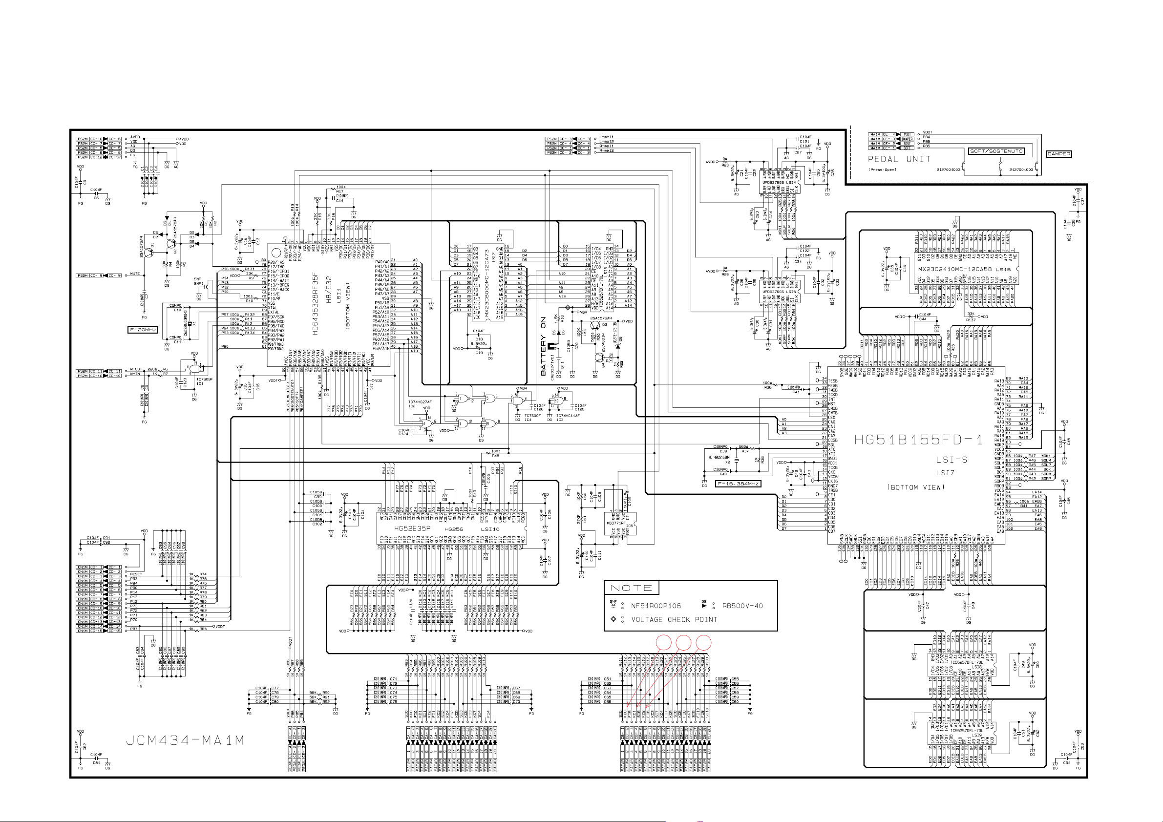
Main PCB JCM434-MA1M
CPU
ROM (8M)
SCHEMATIC DIAGRAMS
RAM
(256K)
D/A
Converter
ROM (24M)
D/A
Converter
Key
controller
Reset IC
DSP
3
5
4
RAM
(256K)
To Pedal Unit
RAM
(256K)
— 25 —
Page 26

I/O PCBs JCM434-PS2M, Phone Jack PCBs JCM434-PS3M, LED PCBs JCM 434-PS4M, Power PCBs JCM 434-PS11
Mute
Power Supply circuit
Power Amp.
Mute
Mixer
Filter
1
2
— 26 —
Page 27

Console PCBs JCM434-CN1M
8
Switch & LED Controller
7
6
— 27 —
Page 28

Console PCBs JCM434-CN2M
— 28 —
Page 29

Keyboard PCB TP20 KY-1
— 29 —
Page 30

Keyboard PCB TP20 KY-2
— 30 —
Page 31

CASIO TECHNO CO.,LTD.
Overseas Service Division
8-11-10, Nishi-Shinjuku
Shinjuku-ku, Tokyo 160-0023, Japan
 Loading...