

Page 1
140CR
Electronic Cash Register
User's Manual
START-UP is QUICK and EASY!
Simple to use!
20 departments and 120 PLUs
Automatic Tax Calculations
Calculator function
CASIO COMPUTER CO., LTD.
6-2, Hon-machi 1-chome
Shibuya-ku, Tokyo 151-8543, Japan
CI
Page 2

INTRODUCTION
Thank you very much for purchasing this CASIO electronic cash register.
START-UP is QUICK and EASY!
Part-1 of this User's Manual can help you make a quick start.
Once you have mastered the QUICK START operations, you will undoubtedly
want to expand your use of this machine by studying other sections of Part-2.
IMPORTANT
FOR PROGRAMMING ASSISTANCE
PLEASE CALL TOLL FREE
1-800-638-9228
CASIO Authorized Service Centers
If your CASIO product needs repair, or you
wish to purchase replacement parts, please call
1-800-YO-CASIO.
Original Carton/Package
If for any reason, this product is to be returned
to the store where purchased, it must be packed
in the original carton/package.
Location
Locate the Cash register on a fl at, stable surface, away from heaters or areas exposed to direct sunlight, humidity or dust.
The mains plug on this equipment must be used to disconnect mains power.
Please ensure that the socket outlet is installed near the equipment and shall be easily
accessible.
E
2
Power Supply
Your cash register is designed to operate on
standard household current (120 V, 50/60 Hz).
Do not overload the outlet by plugging in too
many appliances.
Cleaning
Clean the cash register exterior with a soft cloth
which has been moistened with a solution of a
mild neutral detergent and water, and wrung out.
Be sure that the cloth is thoroughly wrung out to
avoid damage to the printer.
Never use paint thinner, benzene, or other volatile solvents.
Page 3
Safety precautions
To use this product safely and correctly, read this manual thoroughly and operate as instructed.
•
After reading this guide, keep it close at hand for easy reference.
Please keep all informations for future reference.
Always observe the warnings and cautions indicated on the product.
•
About the icons
In this guide various icons are used to highlight safe operation of this product and to prevent injury to the operator and
other personnel and also to prevent damage to property and this product. The icons and defi nitions are given below.
Indicates that there is a risk of severe injury or death if used incorrectly.
Indicates that injury or damage may result if used incorrectly.
Icon examples
To bring attention to risks and possible damage, the following types of icons are used.
The symbol indicates that it includes some symbol for attracting attention (including warning). In this triangle the
actual type of precautions to be taken (electric shock, in this case) is indicated.
symbol indicates a prohibited action. In this symbol the actual type of prohibited actions (disassembly, in this
The
case) will be indicated.
The symbol indicates a restriction. In this symbol the type of actual restriction (removal of the power plug from an
outlet, in this case) is indicated.
Handling the register
Should the register malfunction, start to emit smoke or a strange odor, or otherwise behave abnormally,
immediately shut down the power and unplug the AC plug from the power outlet. Continued use creates the
danger of fi re and electric shock.
• Contact CASIO service representative.
Do not place containers of liquids near the register and do not allow any foreign matter to get into it. Should
water or other foreign matter get into the register, immediately shut down the power and unplug the AC plug
from the power outlet. Continued use creates the danger of short circuit, fi re and electric shock.
• Contact CASIO service representative.
Should you drop the register and damage it, immediately shut down the power and unplug the AC plug from
the power outlet. Continued use creates the danger of short circuit, fi re and electric shock.
• Attempting to repair the register yourself is extremely dangerous. Contact CASIO service representative.
Never try to take the register apart or modify it in any way. High-voltage components inside the register create
the danger of fi re and electric shock.
• Contact CASIO service representative for all repair and maintenance.
INTRODUCTION
Warning!
Power plug and AC outlet
Use only a proper AC electric outlet. Use of an outlet with a different voltage from the rating creates the danger
of malfunction, fi re, and electric shock. Overloading an electric outlet creates the danger of overheating and
fi re.
Make sure the power plug is inserted as far as it will go. Loose plugs create the danger of electric shock,
overheating, and fi re.
• Do not use the register if the plug is damaged. Never connect to a power outlet that is loose.
E
3
Page 4
INTRODUCTION
Warning!
Use a dry cloth to periodically wipe off any dust built up on the prongs of the plug. Humidity can cause poor
insulation and create the danger of electric shock and fi re if dust stays on the prongs.
Do not allow the power cord or plug to become damaged, and never try to modify them in any way. Continued
use of a damaged power cord can cause deterioration of the insulation, exposure of internal wiring, and short
circuit, which creates the danger of electric shock and fi re.
• Contact CASIO service representative whenever the power cord or plug requires repair or maintenance.
Caution!
Do not place the register on an unstable or uneven surface. Doing so can cause the register — especially
when the drawer is open — to fall, creating the danger of malfunction, fi re, and electric shock.
Do not place the register in the following areas.
• Areas where the register will be subject to large amounts of humidity or dust, or directly exposed to hot or cold air.
• Areas exposed to direct sunlight, in a close motor vehicle, or any other area subject to very high temperatures.
The above conditions can cause malfunction, which creates the danger of fi re.
Do not overlay bend the power cord, do not allow it to be caught between desks or other furniture, and never
place heavy objects on top of the power cord. Doing so can cause short circuit or breaking of the power cord,
creating the danger of fi re and electric shock.
Be sure to grasp the plug when unplugging the power cord from the wall outlet. Pulling on the cord can
damage it, break the wiring, or cause short, creating the danger of fi re and electric shock.
Never touch the plug while your hands are wet. Doing so creates the danger of electric shock. Pulling on the
cord can damage it, break the wiring, or cause short, creating the danger of fi re and electric shock.
At least once a year, unplug the power plug and use a dry cloth or vacuum cleaner to clear dust from the area
around the prongs of the power plug.
Never use detergent to clean the power cord, especially power plug.
Keep small parts out of the reach of small children to make sure it is not swallowed accidentally.
E
4
Page 5
Contents
Getting to know your cash register .......................................................................... 6
Daily Job Flow ......................................................................................................... 8
Part-1 QUICK START OPERATION .................................................................
(You can operate this ECR on a basic level by reading the following sections)
1. Initialization ....................................................................................................... 9
2. Loading Paper .................................................................................................. 10
3. Basic Programming for QUICK START – TIME/DATE ...................................... 11
4. Basic Operation after Basic Programming ........................................................ 12
5. Daily Management Report ................................................................................ 15
Part-2 CONVENIENT OPERATION ..................................................................
(Please keep these sections to expand your use.)
1. Various Programming ....................................................................................... 17
2. Various Operations ........................................................................................... 27
Part-3 CALCULATOR FUNCTION ...................................................................
1. Calculator Mode ................................................................................................ 34
Part-4 USEFUL INFORMATION .......................................................................
1. Troubleshooting ................................................................................................ 36
2. Specifi cations .................................................................................................... 36
3. Warranty Card .................................................................................................. 45
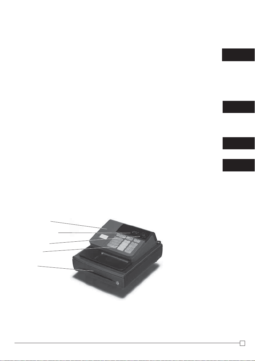
Basic Components and Accessories
Printer cover
9
17
34
36
Operator display
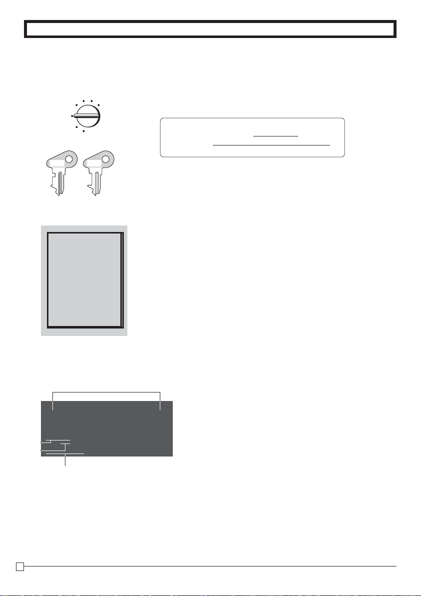
Mode switch
Keyboard
Drawer
Weld lines
Lines may be visible on the exterior of the product. These are “weld lines” that result from the plastic molding process.
They are not cracks or scratches.
Accessories
Roll paper 1 pc
Mode keys
Drawer keys 2 pcs
User's manual 1pc
Magnetic plate* 1 pc
* Use this plate for tacking the notes
received from customer.
OP key 1 pc
PGM key 1 pc
E
5
Page 6
GETTING TO KNOW YOUR CASH REGISTER
Getting to know your cash register
Mode Switch
REG
OFF
RF
PGM
OP
OP key PGM key
Note:
An error is generated (E01 displayed) whenever
the position of the
Mode Switch is
changed during
registration.
Display
PGM
The position of the Mode Switch controls the type of operations you
XCAL
Z
can perform on the cash register. The PROGRAM key (marked PGM)
can be select any Mode Switch setting, while OPERATOR key (marked
OP) can be used to select OFF, REG or CAL only.
PGM RF OFF REG CAL X Z
OP key
● ● ●
PGM key
● ● ● ● ● ● ●
OFF
In this position, the power of the cash register is off.
REG (Register)
This is the position used for registration of normal transactions.
RF (Refund)
This is the position used for registration of refunds.
CAL (Calculator)
This is the position used for calculator mode.
PGM (Programming)
This is the position used to program the cash register to suit the
needs of your store.
X (Read)
This is the position used to produce reports of daily sales totals without clearing the totals.
Z (Reset)
This is the position used to produce reports of daily sales totals. This
setting clears the totals.
!
Department Number Display
!
Anytime you press a department key to register a unit
price, the corresponding department number appears
here.
PLU Number Display
@
Anytime you perform a PLU registration, the corresponding PLU number appears here.
E
6
Number of Repeat Display
#
Anytime you perform "repeat registration" (page 12),
the number of repeats appears here.
Note that only one digit is displayed for the number of
repeats.
Numeric Display
$
Entered values (unit prices or quantities) and calculated values (subtotals, totals or change amount due)
are displayed here. The capacity of the display is 8
digits.
This part of the display can be used to show the current time or date between registration (page 31).
Page 7
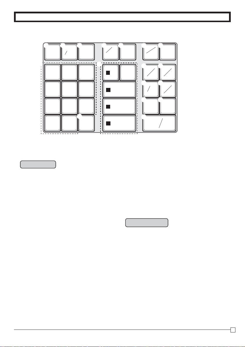
Keyboard
GETTING TO KNOW YOUR CASH REGISTER
s
FOR
FEED PLU
DATE
TIME
AC
& (
7
8
9
4
5
6
1
2
3
'
0
00
Certain keys have two functions; one for register mode and one for calculator mode.
In this manual, we will refer to specifi c keys as noted below to make the operations as easy to
understand as possible:
—
C
.
ERR.
CORR
w
9/14/19
s
4
10/15/20
8/13/18
TAXABLE
7/12/17
NON-TAX
6/11/16
5
3
2
1
%
CLK#
RA
T/S1
"
#
DEPT
SHIFT
#
$
SUB
TOTAL
%
CA AMT
=
TAX
PGM
PO
T/S2
CHK
NS
CH
TEND
Register Mode
! l
@ h
# t
g
$
% i
^ :
&
~
* c
( v
) j
Q m
W k
E u
R p
T
?, Z
"
Y
U G, S, D, F, [
Feed key
Multiplication/Split pricing/Date Time key
Clear key
Minus/Error Correction key
PLU (Price Look Up) key
Percent/Cashier ID No. Assignment key
Tax Program key
Received on Account/Tax Status Shift 1 key
Paid Out/Tax Status Shift 2 key
Reference Number/Department Shift key
Check/No Sale key
Subtotal key
Charge key
Cash Amount Tendered key
, ~ >,
Numeric keys and 2-zero key
Decimal key
Department keys
'
• Department 6 through 20 are specifi ed by
pressing the j key respectively as follows:
jG ~ j[
jjG ~ jj[
jjjG ~ jjj[
→
Department 6 ~ 10
→
Department 11 ~ 15
→
Department 16 ~ 20
Calculator Mode
AC key
# t
Memory Recall key
% i
Percent key
^ :
Q m
R p
?, Z
T
Y
"
U H, J, K, L
Drawer Open key
Equal key
, ~ >,
Numeric keys and 2-zero key
Decimal key
Arithmetic Operation key
'
E
7
Page 8
Daily Job Flow
Daily Job Flow
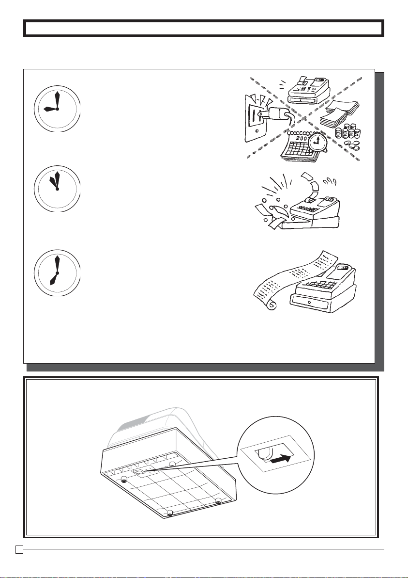
Before Opening The Store
1. Plugged in?
2. Enough Roll Paper? Page-10
3. Date and Time is correct? Page-31
4. Enough small change in the drawer? Page-32
While The Store Is Open
1. Registrations. Page-12~
2. Issuing latest daily sales total if
needed.
(Generating report by Mode Switch
to X position.) Page-15
After Closing The Store
1. Issuing Daily Sales Total.
(Resetting report by Mode Switch to
Z position.) Page-15
2. Picking up money in the drawer.
Page-32
3. Turn the Mode Switch to OFF.
Other
1. Troubleshooting Page-36
When the cash drawer does not open!
In case of power failure or the machine is in malfunction, the cash drawer does not open automatically. Even in
these cases, you can open the cash drawer by pulling drawer release lever (see below).
Important!
The drawer will not open, if it is locked with a drawer lock key.
E
8
Page 9
Part-1
Part-1 QUICK START OPERATION
QUICK START OPERATION
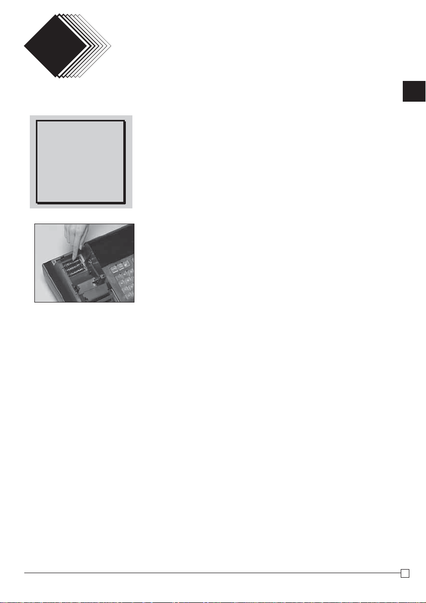
1. Initialization and Loading Memory Protection Battery
To initialize the cash register
Important
You must initialize
the Cash register and
install the memory
protection batteries
before you can program the cash register.
(Figure 1)
◗
1. Set the Mode Switch to OFF.
2. Load the memory protection batteries.
3. Plug the power cord of the cash register into an AC outlet.
4. Set the Mode Switch to REG.
To load the memory protection batteries
◗
1. Remove the printer cover.
2. Open the battery compartment cover.
3. Load 3 new SUM-3 ("AA") type batteries into the compartment.
Be sure that the plus (+) and minus (–) ends of each battery are
facing in the directions indicated by the illustrations inside the
battery compartment (Figure 1).
4. Replace the memory protection battery compartment cover
back into place.
5. Replace the printer paper and printer cover.
REPLACE MEMORY PROTECTION BATTERIES AT LEAST
ONCE EVERY YEAR.
Part-1
E
9
9
Page 10
Part-1 QUICK START OPERATION
2. Loading Paper Roll And Replacing The Printer’s Ink Roll
Press the l key to take up
Mode Switch
CAL
X
REG
OFF
RF
Z
PGM
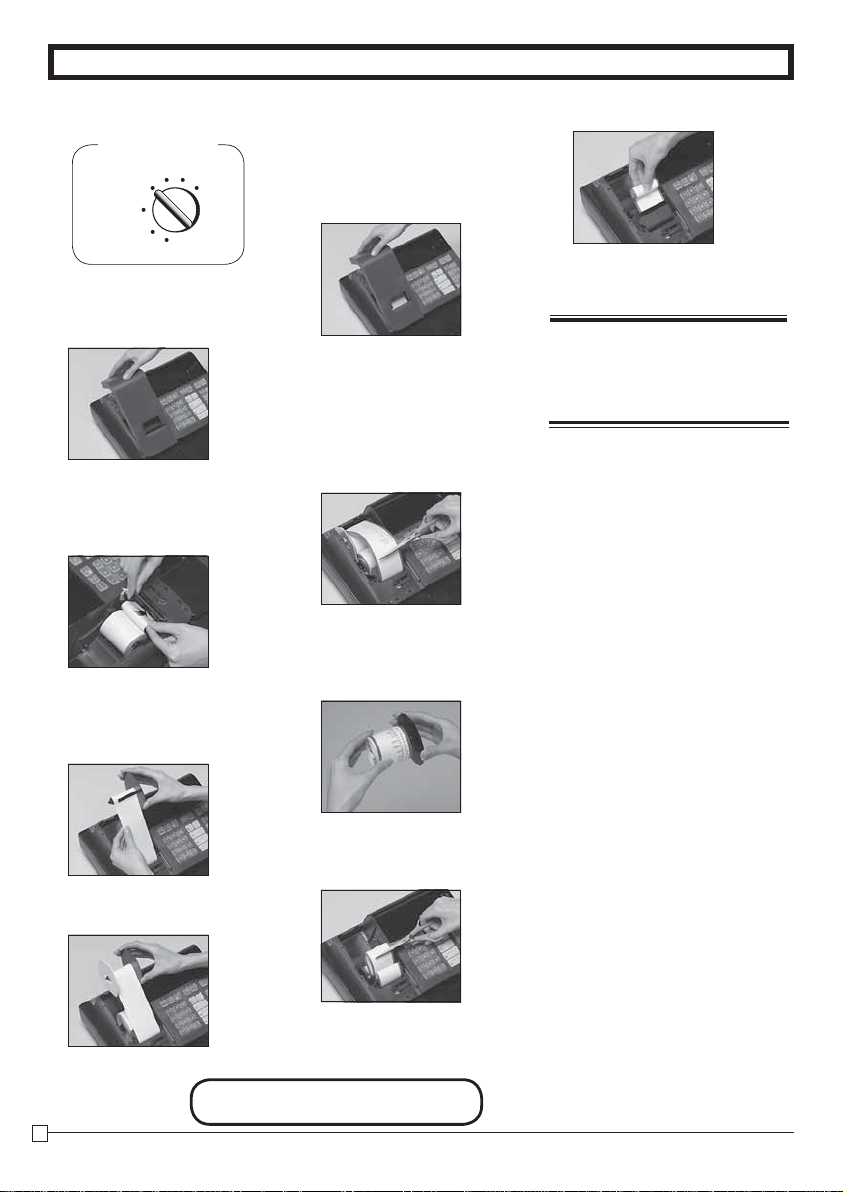
1. To load journal paper
Remove the printer cover by
!
lifting up the back.
Put a roll of journal paper
@
into the holder.
Cut the leading end of the
#
roll paper with scissors and
insert the paper into the inlet.
Press the l key until 20 or
$
30 cm of paper is fed from
the printer.
Roll the paper onto the take-
%
up reel a few turns.
&
any slack in the paper.
Replace the printer cover by
*
placing the cover’s front tab
into the register’s groove.
2. To remove journal paper
Remove the printer cover fol-
!
lowing the instructions above.
Press the l key until ap-
@
proximately 20cm of the paper is fed from the printer.
Cut off the roll paper.
#
Remove the take-up reel
$
from the printer and take off
the left plate of the reel.
Remove the journal paper
%
from the take-up reel.
Load new paper following the
*
instructions above, and replace the printer cover.
Default printer setting is for
Journal.To print receipts, please
refer to 1-7-3 on page 22 to
switch the printer for Receipt or
Journal.
To load receipt paper
◗
To use the printer to print re-
!
ceipts, follow steps 1 through
4 of “To load journal paper”.
Pass the leading end of the
@
receipt paper through the
printer cover’s paper outlet
and replace the printer cover.
Tear off any excess paper.
#
Set the left plate of the take-
^
up reel and place the reel
into the register.
E
10
Cut off the paper left in the
^
printer and press the
until the remaining paper is
fed out from the printer.
Remove the core of the pa-
&
per.
Options: Roll paper – P-5860
Ink Roll – IR-40
l
key
Page 11
Part-1 QUICK START OPERATION
3. Basic Programming for QUICK START
Procedure
1. Turn the mode switch to PGM position.
2. When the display shows blinking “0”, such as
enter current date in Month, Day, Year order.
Example: January 8, 2010: enter
?Z?<Z?
• Enter 6-digit, last 2 digits for year set. (
• By pressing y, this procedure returns one by one.
3. When the display shows blinking “0”, such as
enter current time in Hour, Minute order.
Example: 1:18 PM, enter
ZCZ<
• Enter 4-digit, use 24-hour system.
• By pressing y, this procedure returns one by one.
• If you want to adjust the date/ time, please refer to page 31 of this manual.
4. Input the desired fl at tax rate to the appropriate department key.
(This procedure below programs fl at tax rate only. If your tax table has break points, refer
to page 24 of this manual.)
A) Press the
~
key.
B) Enter tax rate. (Example: For 6% enter “6”, 5.75% enter “5.75”.)
C) Press the appropriate department key.
D) Repeat step B) and C) to set other department key.
E) Press the k key to end tax programming.
Note: In case of setting the wrong tax rate to the key, please enter
department keys above, and quit this procedure by pressing k key, and start from
the beginning of this procedure.
Please start with the department 2 key (taxable department). Department 1 key is
initialized as non taxable.
Example 1:
Set state tax 4% to department 2, 3 key.
4S
4
Start tax program.
~
Enter tax rate and press dept key.
Enter tax rate and press dept key.
D
To end the setting.
k
00-00-00
,
2010 → 10)
00-00
,
and press those
?
Example 2:
Set state tax 5% to department 2 and 7% to
department 3 key.
5
7
Start tax program.
~
Enter tax rate and press dept key.
S
Enter tax rate and press dept key.
D
To end the setting.
k
Mode Switch
CAL X
REG
OFF
RF
Z
PGM
Purpose
Programming
Setting the
current date
Setting the
current time
Setting the tax
rates
Part-1
FOR PROGRAMMING ASSISTANCE, PLEASE CALL TOLL FREE 1-800-638-9228
11
E
11
Page 12
Part-1 QUICK START OPERATION
4. Basic Operation after Basic Programming
Note:
Whenever an error is generated, the input fi gures reset to 0.
All printout samples are journal images and the header (date, time
and consecutive no.) are eliminated from the samples.
Operation
4-1 Open the drawer
m
without a sale
4-2 Basic operation
Z?? S
Example
Unit Price $1.00 $2.00 $0.30
j
Quantity 1 1 1
Dept. 2 10 15
Cash
jj
Amount
tendered
$5.00
k
4-3 Multiple regis-
tration on the
S
same items
C h
Example
Unit Price $1.00 $1.35
Quantity 2 3
Dept. 2 2
k
p
Unit Price Department 2
X?? [
Department 10
C? [
Department 15
B?? p
Cash amount tendered
Departments 6 through 10, 11 through 15, 16 through 20 can also be registered in combination with the j and G, S, D, F or [ keys, respectively. The j key should be entered just before entering unit price manually.
Z?? S
Unit Price Department 2
Quantity Multiple key
ZCB S
Note that repeated registration can be used with unit prices up to 6 digits long.
Printout
•••••••••• N
02 •1•00 t1
10 •2•00
15 •0•30
•1•00 T
•0•04 t1
•3•34 S
•5•00 C
•1•66 G
02 •1•00 t1
02 •1•00 t1
3 X
•1•35 @
02 •4•05 t1
•6•05 T
•0•24 t1
•6•29 C
Mode Switch
CAL
REG
OFF
RF
PGM
— No Sales Symbol
Department No./Unit Price
—
— Taxable Subtotal
— Tax
— Subtototal
—
Cash Amount Tendered
—
Change Amount Due
— Repeat
— Sales Quantity
— Unit Price
X
Z
4-4 Split sales of
packaged items
Example
Unit Price 12$10.00
Quantity 3
Dept. 2
k
Package Quantity Multiple key
C h
Sales Quantity Multiple key
ZX h
Z?' S
Package Price
p
E
12
3 X
12
•10•00 @
02 •2•50 t1
•2•50 T
•0•10 t1
•2•60 C
— Sales Quantity
— Package Quantity
— Unit Price
Page 13
Part-1 QUICK START OPERATION
Mode Switch
CAL
X
REG
OFF
RF
Z
PGM
Part-1
Operation
Z?? G
4-5 Charge sales
Example
Unit Price $1.00 $2.00 $3.00
k
Quantity 1 1 1
Dept. 1 2 1
u
X?? S
C?? G
Charge key
You cannot perform the amount tendered operation using the u key.
4-6 Split cash/
charge sales
Example
k
Unit Price $2.00 $3.00 $4.00
Quantity 1 1 1
u
Dept. 1 2 1
Cash
Amount
tendered
$5.00
4-7 Corrections
X?? G
C?? S
V?? G
B?? p
Corrections can be made while you are registering the item (before you
press a department key), or after it has already been registered into the
memory (by pressing a department key).
4-7-1 Before you
press a department key
y
key clears the last item entered.
Operation
Printout
01 •1•00
02 •2•00 t1
01 •3•00
•2•00 T
•0•08 t1
•6•08 H
01 •2•00
02 •3•00 t1
01 •4•00
•3•00 T
•0•12 t1
•9•12 S
•5•00 C
•4•12 H
— Charge Sales
—
Cash Amount Tendered
— Charge Sales
Printout
Example
1. Entered 400 for unit
price by mistake
instead of 100.
Z?? G
V?? y
Wrong entry Clears the last item entered.
Correct entry Registered Depar tment 1
01 •1•00
E
13
Page 14
Part-1 QUICK START OPERATION
Operation
2. Entered unit price
X?? h
fi rst instead of
quantity and then
pressed h.
y
Unit price
Multiplication
Clears the last item entered.
B h
Quantity
Multiplication
X?? S
Unit price
3. Entered 150 for unit
Z? h
price by mistake
instead of 105.
Quantity
ZB? y
Wrong entry Clears the last item entered.
Z?B D
Correct entry
Registered Department 2
Multiplication
Z? h
Quantity
Registered Department 3
4-7-2 After you
pressed a department key
Example
1. Entered unit price 550
by mistake instead of
g
505 and pressed a
department key.
B?B G
key cancels the last registered item.
g
BB? G
Wrong entry
Cancels the last item registered.
Correct entry
Registered Department 1
Printout
5 X
•2•00 @
02 •10•00 t1
10 X
•1•05 @
03 •10•50
01 •5•50
-5•50 V
01 •5•05
2. Entered unit price 220
C h
by mistake instead of
230 and pressed a
department key.
g
E
Quantity
XX? S
Wrong entry
Cancels the last item registered.
C h
XC? S
Correct entry
14
Multiplication
Registered Department 2
3 X
•2•20 @
02 •6•60 t1
-6•60 V
3 X
•2•30 @
02 •6•90 t1
Page 15

5. Daily Management Report
This section tells you the procedures to use to produce reports of the transaction data stored in the cash register's memory.
Part-1 QUICK START OPERATION
Important
Remember that when you issue a reset (Z) report, the data that is reported is cleared from the applicable totalizers. To view data without clearing totalizers, issue a read (X) report.
5-1 Financial Report
h
Mode Switch
X
CAL
REG
OFF
RF
Z
PGM
5-2 General Control
Operation
Operation
Read/Reset
Report
5-2-1 Daily Read/Reset
Report
Mode Switch to X (Read)
p
Mode Switch to
p
Mode Switch
CAL X
REG
OFF
RF
PGM
(Reset)
Z
Z
Printout
01-08-10
14-27 0072
X
67 *
•270•48 *
38 n
•271•24 n
•197•57 C #
•18•19 H #
•45•18 * K
Printout
— Date
— Time/Consecutive No.
— Read Symbol
— Gross Sales No. of Items
— Gross Sales Amount
— Net Sales No. of Customers
— Net Sales Amount
— Cash Total in Drawer
— Charge Total in Drawer
— Check Total in Drawer
Z (Reset) report
01-08-10
19-35 0073 1
0001 Z
01 48
•50•10
02 28
•76•40
03 17
•85•80
04 4
•76•00
05 1
•6•50
06 1
•1•00
19 2
•1•00
20 5
•10•00
108 *
•316•80 *
— Date
Time/Consecutive No. /Clerk
—
No.
Non-resettable Sales No.
—
of Resets*1/RESET Symbol*
— No. of Items/Dept. No.
— Amount
— Gross Sales No. of Items
— Gross Sales Amount
Part-1
1
E
15
Page 16

Part-1 QUICK START OPERATION
•0•50 -
•0•66 % -
•105•10 T
•4•20 t1
•75•60 * T
•3•97 t ™
46 n
•325•13 n
•325•13 1
— Reduction Amount
—
— Taxable Amount 1
— Tax Amount 1
— Taxable Amount 2
— Tax Amount 2
— Net Sales No. of Customers
— Net Sales Amount
— Clerk 1 Sales Amount
(Refer to 2-10 Cashier Assignment)
44 C
•203•91 C
3 H
•16•22 H
2 K
•105•00 K
•6•00 R
•10•00 P
3 V
1 r
•3•00 r
5 C X
— Cash Sales Count
— Cash Sales Amount
— Charge Sales Count
— Charge Sales Amount
— Check Sales Count
— Check Sales Amount
—
— Paid Out Amount
— Error Correction Count
— RF Mode Count
— RF Mode Amount
— No. of
CAL mode
1 N
•199•91 C #
•16•22 H #
•105•00 * K
000000
0325•13
— No-sales Count
— Cash in Drawer
— Charge in Drawer
— Check in Drawer
Premium/Discount Amount
Received on Account Amount
key operation in
p
Non-resettable Grand Sales Total
(printed only on RESET report)*
2
5-2-2 Periodic Read/
Operation
Reset Report
Mode Switch to Z or
Z? p
E
16
X
* X (Read) report is the same except *1 and
Printout
01-08-10
19-50 0074
10 •••• X
X
67 *
•270•73 *
38 n
•271•24 n
— Date
— Time/Consecutive No.
Periodic
Read Symbol
— Gross Sales No. of Items
— Gross Sales Amount
— Net Sales No. of Customers
— Net Sales Amount
*2
.
Page 17

Part-2 CONVENIENT OPERATION
Part 2
CONVENIENT OPERATION
1. Various Programming
1-1 Unit price for
Departments
Example
Unit Price $1.00 $2.20 $11.00
Dept. 1 2 3
ZZ?? D
k
1-2 Rate for per-
cent key
Example
X"B :
Discount Rate 2.5%
k
Z k
P appears in mode display
Z?? G
XX? S
Z k
P appears in mode display
(To end the setting)
Mode Switch
CAL X
REG
OFF
RF
PGM
(For Dept. 1)
(For Dept. 2)
(For Dept. 3)
• Unit prices within the range of 0.01~9999.99.
• The rate within the range of 00.01 to 99.99%.
Z
Part-2
1-3 To change tax
status for
Departments
Z k
Example
Status
mGSDF[
Dept. 1 ~ 5 6 ~ 10
Non-
Taxable
Taxable
Tax status for the Departments are fi xed as follows:
Department 2: Taxable status 1.
Departments 1, 3~20: Non-Taxable status.
~
P appears in mode display
Select key
from list A
For Depts. 1, 2, 3, 4 and 5
cjGjSjDjFj[
Taxable status 1
For Depts. 6, 7, 8, 9 and 10
k
(To end the setting)
Taxable status 1
Taxable status 2
Taxable status 1 and 2
Taxable status 3
Taxable status 1, 2 and 3
Taxable status 4
Non-taxable status
Selections
c
v
c
v
u
cvu
A
h
m
E
17
Page 18

Part-2 CONVENIENT OPERATION
1-4 Status for
Department
Example
C k
Depts.
1 041
2 051
?BZ S
k
Selections
ABC
P3 appears in mode display
?VZ G
Select a number
from list A
Normal department
Normal department
Minus department
No limitation for manually entered price.
Maximum number of digits for manually entered price.
(1 ~ 7 digits)
To prohibit manual price entries.
Normal sales (not a single-item sale) department
Set as a single-item sale department
Select a number from list B
Maximum No. of digits to be 5
(To end the setting)
Selections
For Dept. 1
For Dept. 2
Select a number
from list C
Single item sale
department
?
Z
?
~
Z
M
or
<
>
?
Z
A
B
C
1-5 Status for percent key
1-5-1 To change tax-
able status for the
percent key
Z k
Example
Change Percent key
m:
registration as a Nontaxable.
k
E
18
Taxable status 1 is fi xed for the percent key.
P appears in mode display
Select key from list A
(To end the setting)
Taxable status 1
Taxable status 2
Taxable status 1 and 2
Taxable status 3
Taxable status 1, 2 and 3
Taxable status 4
Non-taxable status
Selections
~
(For percent key)
c
v
c
v
u
cvu
h
m
A
Page 19

C k
1-5-2 Status for
percent key
Example
Round Up
Percent %+
k
P3 appears in mode display
ZZ :
Select a number
from list A
Select a number
from list B
(To end the setting)
Part-2 CONVENIENT OPERATION
Mode Switch
CAL X
REG
OFF
RF
Z
PGM
Part-2
Rounding of results produced by Percent Key operation.
Round off (1.544=1.54; 1.545=1.55)
Round up (1.544=1.55; 1.545=1.55)
Cut off (1.544=1.54; 1.545=1.54)
Program Percent Key to register discounts (%–).
Program Percent Key to register premiums (%+).
Program Percent Key to function as a Manual Tax key.
1-6 Taxable Status
for minus key
Z k
Example
Change minus key
registrations
mg
Non-taxable status.
Non-taxable status is fi xed for the minus key.
P appears in mode display
Select key from list A
Selections
~
k
(To end the setting)
Taxable status 1
Taxable status 2
Taxable status 1 and 2
Taxable status 3
Taxable status 1, 2 and 3
Taxable status 4
Non-taxable status
Selections
Minus key
?
Z
X
?
Z
X
c
v
c
v
u
cvu
h
m
A
B
A
E
19
Page 20

Part-2 CONVENIENT OPERATION
1-7 General features
1-7-1 To set general
controls
C k
P3 appears in mode display
Select a number from list A
Select a number from list B
Select a number from list C
?NXX k
Program code No.
???? p
k
(To end the setting)
Select a number from list D
Selections
Time display format: HH-MM
Time display format: HH-MM SS
?
V
A
Maintain key buffer during receipt issue in
REG mode.
Reset the transaction number to
zero whenever a General Control
Reset Report is issued.
Allow credit balance registration.
No
Ye s
Allow partial cash amount tendered.
Allow partial check amount ten-
dered.
Ye s
No
Use the
Cashier assignment systems (sign
on) is used.
E
key as a 000 key.
'
No
Ye s
Ye s
No
Ye s
No
Selections
Ye s
No
Ye s
No
Ye s
No
Ye s
No
Selections
Ye s
No
Ye s
No
Selections
No
Ye s
No
Ye s
?
Z
X
C
V
B
N
M
?
X
V
N
?
Z
X
C
B
C
D
20
Page 21

1-7-2 To set printing
C k
controls
P3 appears in mode display
Select a number from list A
k
Select a number from list B
Select a number from list C
Select a number from list D
?BXX k
Program code No.
???? p
(To end the setting)
Part-2 CONVENIENT OPERATION
Mode Switch
CAL X
REG
OFF
RF
Z
PGM
Selections
Use the printer to print a journal.
Use the printer to print receipts.
Ye s
No
No
Ye s
Selections
No
Ye s
No
Ye s
No
Ye s
No
Ye s
Ye s
No
Ye s
No
Ye s
No
Ye s
No
Ye s
No
Ye s
No
Ye s
No
Ye s
No
Print zero-total line on the General Control
Read/Reset Reports
Do not print zero-total line on the General
Control Read/Reset Reports.
Print RF switch mode refund count/
amount on the General Control Read/Reset Reports.
Print the grand sales total on the
General Control Reset Reports.
Print the time on the receipt
and journal.
Print the consecutive number on the receipt/journal.
Print the subtotal on the receipt/
journal when the Subtotal Key is
pressed.
Skip item print on journal.
?
A
Z
?
B
Z
Selections
?
Z
X
C
C
V
B
N
M
Selections
?
Z
X
C
D
V
B
N
M
Part-2
E
21
Page 22

Part-2 CONVENIENT OPERATION
1-7-3 Printer switch for
Receipt or Journal
Z k
Example
To print a receipt.
Z u
k
The printer is fi xed as journal after initialized operation.
P appears in mode display
Select a number from list A
(To end the setting)
1-8 PLU setting
C k
1-8-1 Linkage with
Departments
ZiZ p
Example
PLU No. 1 100
Link Dept. No 1 10
k
P3 appears in mode display
PLU No.
Select numbers from list A
Z?? i
PLU No.
Z? p
Dept. No. to be linked
(To end the setting)
Use the printer to print a journal.
A
Use the printer to print receipts.
Selections
?
Z
• Printer selection to print a journal or
receipts can also be set on procedures 1-7-2 “To set printing controls”.
Linked to dept. 20.
Linked depts. 1~20 respectively.
A
Selections
?
Z~ X?
• 120 PLUs can be set.
• When the linked department is not specifi ed, the PLU is linked to department 20.
• Status for a single-item sale and tax status
are followed the specifi ed linked department.
E
22
Page 23

1-8-2 Unit Prices
for PLUs
Z k
Example
PLU No. 1 2
Unit Price $1.00 $3.00
P appears in mode display
Z i
PLU No.
Z?? p
Unit Price
X i
PLU No.
C?? p
Unit Price
k
(To end the setting)
1-9 To control
Tax Status
printing
Example
Print taxable amount and tax
amount for Add-in.
?CXN k
Program set code No.
Select a
number
from list A
k
C k
P3 appears in mode display
??? p
Select a
number
from list B
Enter “0”
(fi xed code)
(To end the setting)
Part-2 CONVENIENT OPERATION
Mode Switch
CAL X
REG
OFF
RF
Z
PGM
• Unit prices within the range of $0.01~999.99.
Part-2
Selections
Print Tax status symbols.
Do not print Tax status symbols.
Print taxable amount.
Print taxable amount and tax
amount for Add-in.
Ye s
No
Selections
Ye s
No
Ye s
No
?
X
?
Z
X
C
A
B
E
23
Page 24

Part-2 CONVENIENT OPERATION
Mode Switch
CAL X
Z
1-10 To program
Tax Table
REG
OFF
RF
PGM
If your tax table is not a fl at table (includes break points), fi nd the tax table for your state on pages
37 through 44 of this manual. Follow the procedures below to set the tax tables.
Example 1: Set Alabama state tax 4%.
C k
? Z X B k
Z ? p
Z Z ? p
? p
Z p
Z p
C ? p
B V p
M C p
k
P3 appears in mode display
Program set code No. for tax table 1
1st code for 4%
Last code for 4%
(to end the setting)
ALABAMA
5%
6%
4%
0
0
0
1
1
1
1
1
1
10
8
10
29
24
30
49
41
54
69
58
73
89
110
110
Note: If your table has break points, set it to this table (tax table 1).
Example 2: Set Colorado state tax 5.25%.
C k
? X X B k
B " X B p
B ? ? X p
k
P3 appears in mode display
Program set code No. for Tax table 2
5.25% tax
50 for Round off and 02 for Add On
(to end the setting)
COLORADO
5.25%
5.25
5002
• This sample programming can set only tax rate, but not for a tax break point.
• You can set tax table 3 and 4 by the set code No. 0325 (for table 3) and 0425 (for table 4)
Tax status for the Departments and function keys are fi xed as follows:
Department 2: Taxable status 1.
Departments 1, 3~20: Non-Taxable status.
Percent key: Taxable status 1.
Minus key: Non-Taxable status.
6%
0
1
1
9
20
40
55
70
90
109
• See page 17 (department key), 18 (percent key), 19 (minus key) to change the fi xed tax status.
E
24
Page 25

Part-2 CONVENIENT OPERATION
1-11 Printing to
read All
Preset Data
1-11-1 Printing preset
data except
PLU settings
Mode Switch
CAL X
REG
OFF
RF
Z
PGM
Operation
p
Printout
01-08-10
14-24 0070
X
01••••1•00
01-041
02••••2•20
02-051
03•••11•00
03-041
20••••0•00
00-000
-••••••03
2•5 %
03-11
0122••••12
0222••0000
0522••0022
0622••0000
1022•••••0
0326•••002
0125••••••
0•0000 %
0001
0001
10
30
54
73
110
0225••••••
5•2500 %
5002
0000
01-08-10
— Date
— Time/Consecutive No.
— Read Symbol
Dept. No./Unit Price
—
Tax Status/Normal Dept./
—
Digit Limit/Single Item
— Minus/Tax Status
— Percent Rate/%+ or %–
Tax Status/Percent Key Control
—
Date/Add Mode Control (fi xed)
—
— Print Control
— General Control
— Calculation Control
— Tax Control
— Tax Table 1
Break Points Control
— Tax Table 2
Rounding Specifi cations/
—
Tax System Specifi cations
Part-2
Tax Status
Printout Meaning Printout Meaning Printout Meaning
00 Non taxable 06 Taxable 1 & 3 12 Taxable 1, 2 & 4
01 Taxable 1 07 Taxable 1 & 4 13 Taxable 1, 3 & 4
02 Taxable 2 08 Taxable 2 & 3 14 Taxable 2, 3 & 4
03 Taxable 3 09 Taxable 2 & 4 15 All taxable
04 Taxable 4 10 Taxable 3 & 4
05 Taxable 1 & 2 11 Taxable 1, 2 & 3
E
25
Page 26

Part-2 CONVENIENT OPERATION
Mode Switch
CAL X
REG
OFF
RF
Z
PGM
1-11-2 Printing pre-
Operation
set PLU settings
Z p
Printout
01-08-10
14-26 0073
X
001•••1•00
01
002•••2•00
02
003•••3•00
03
004•••4•00
099•••0•00
19
100••10•00
20
01-08-10
— Date
— Time/Consecutive No.
— Read symbol
— PLU No./Unit Price
— Linked department
E
26
Page 27

Part-2 CONVENIENT OPERATION
2. Various Operations
2-1 Registration using
preset price
for Departments.
(Programming: See page 17)
Operation
Example
G
Unit Price $1.00 $2.20 $11.00
S
Quantity 1 2 4
Depts. 1 2 3
S
Amount
Tendered
k
2-2 Single-Item Sales
(Programming: See page 18)
B? D
Example 1
Status Single item sale
Unit Price $0.50
Quantity 1
Dept. 3
$50.00
B??? p
V hD
Printout
01 •1•00
02 •2•20 t1
02 •2•20 t1
4 X
•11•00 @
03 •44•00
•4•40 T
•0•18 t1
•49•58 S
•50•00 C
•0•42 G
03 •0•50
•0•50 C
Mode Switch
CAL
X
REG
OFF
RF
Unit Price
—
— Unit Price
— Repeat
— Multiplication Symbol
— Unit Price
— Cash Amount Tendered
— Change
— Cash Sales
Z
PGM
Part-2
For this example, Dept. 1 is programmed for a single-item-sale.
(Programming: See page 23.)
Example 2
Status Normal Single item sale
k
Unit Price $1.00 $0.50
Quantity 1 1
p
Dept. 2 3
Z?? S
B? D
Single-item sale cannot be fi nalized if an item is registered previously.
02 •1•00 t1
03 •0•50
•1•00 T
•0•04 t1
•1•54 C
— Taxable Amount
— Tax
— Cash Sales
E
27
Page 28

Part-2 CONVENIENT OPERATION
Mode Switch
CAL
REG
OFF
RF
PGM
X
Z
2-3 Check Sales
Example
Unit Price $35.00
F
Quantity 2
k
Depts. 4
Operation
CB?? F
m
2-4 Change the Tax
Status
Example
c
Unit Price $1.00 $2.00
Quantity 1 1
Depts. 1 2
Preset Status
p
This
Registration
Non-
Ta xa b l e
Taxable 1 Taxable 1
Taxable 1
Z?? G
X?? S
2-5 Manual Tax
Z?? G
Example
Unit Price $1.00 $2.00
Quantity 1 1
Depts. 1 2
p
Z? :
X?? S
Printout
04 •35•00
04 •35•00
•70•00 K
01 •1•00 t1
02 •2•00 t1
•3•00 T
•0•12 t1
•3•12 C
01 •1•00
•0•10 t #
02 •2•00 t1
•2•00 T
•0•08 t1
•3•18 C
— Check Sales
— Manual Tax Symbol
:
key is programmed to function as a Manual Tax key (see page 19).
E
28
Page 29

Part-2 CONVENIENT OPERATION
2-6 PLU operation
(Programming: See page 23)
i
Example
PLU No. 1 2
Unit Price $1.00 $2.00
p
Quantity 2 4
Link Dept. No. 2 2
Cash Amount
tendered
2-7 PLU Single-Item Sale
$10.40
(Programming: See page 22)
Example
PLU No. 1
Status Single item sale
Unit Price $1.00
Quantity 1
2-8 Split cash/
check sales
k
Example
Unit Price $30.00 $25.00
m
Quantity 1 1
Depts. 2 3
Cash Amount
tendered
Check $36.20
$20.00
C??? S
XB?? D
X??? p
Z i
V h
X i
Z i
• For this example, linked department 1 is programmed for a single-item-sale.
• Single-item sale cannot be fi nalized if an item is registered previously.
001 •1•00 t1
001 •1•00 t1
4 X
•2•00 @
002 •8•00 t1
•10•00 T
•0•40 t1
•10•40 C
001 •1•00 t1
•1•00 T
•0•04 t1
•1•04 C
02 •30•00 t1
03 •25•00
•30•00 T
•1•20 t1
•56•20 S
•20•00 C
•36•20 K
PLU No.
— Repeat
— Multiplication Symbol
— Preset Unit Price
— Cash Amount Tendered
PLU No.
— Taxable Status Symbol
— Taxable Amount
— Tax
Part-2
E
29
Page 30

Part-2 CONVENIENT OPERATION
Mode Switch
CAL
X
REG
OFF
RF
PGM
Z
2-9 Refund
Z?? S
Example
Unit Price $1.00 $2.00
Quantity 1 1
k
Depts. 2 3
Operation
X?? D
p
After you fi nish RF mode operation, be sure to re-
Printout
13-55 0040 r
02 •1•00 t1
03 •2•00
•1•00 T
•0•04 t1
•3•04 C
— Refund Mode Symbol
turn the Mode Switch to the REG (register) setting.
2-10 Cashier
Assignment
(Programming: See page 20)
Mode Switch
In any mode
REG, RF, CAL,
X or Z,
except PGM
Cashier assignment system is used to control each cashier (or clerk) sales total. When you select
this function on page 20, you can get 8 cashiers (or clerk) sales data.
Cashier assignment must be performed prior to starting registration or any other operation, except
Program mode.
Z :
Select a number
from list A
Selections
Sign off (cancel) the assignment of cashier ID No.
Assign a cashier ID No. 1 through 8. Z ~
?
<
A
• Currently assigned cashier (or clerk) ID number is printed on the receipt or journal for each transaction.
• The assigned clerk memory number is automatically signed off when the mode key is set to OFF
position.
• The assigned cashier (or clerk) sales totals with ID number are printed on the receipt or journal
when you perform daily X/Z sales report.
E
30
Page 31

2-11 Other registrations
Part-2 CONVENIENT OPERATION
Mode Switch
CAL
X
REG
OFF
RF
Z
PGM
Operation
h
2-11-1 Reading the
Time and Date
h
y
Adjusting the Time
Example
Current time = 13:58
Operation
• Turn the Mode Switch to PGM.
Zk
ZCB<h
Current Time: Hour Minute
Adjusting the Date
Example
Current date = January 8, 2010
y
Operation
• Turn the Mode Switch to PGM.
Zk
Display
13-5#
01-08-10
Hour/Minute
Month/Date/Year
~00
• Flashes per second
Display
p ~00
13-58 02
~00
• Enter current time in 24 hour system.
Display
p ~00
Mode Switch
CAL X
REG
OFF
RF
Z
PGM
Mode Switch
CAL X
REG
OFF
RF
Z
PGM
Part-2
?Z?<Z?h
Current date: Month Day Year
y
01-08-10
~00
• Enter current date in 6 digits.
• Enter the last 2 digits for year set. (2010 → 10)
E
31
Page 32

Part-2 CONVENIENT OPERATION
Mode Switch
CAL
REG
OFF
RF
PGM
X
Z
Operation
2-11-2 Paid out from
ZXCV
cash in drawer
2-11-3 Cash
BNM< j
Enter reference No.
Z??? v
Operation
N?? c
received on
account
Operation
2-11-4 Registering
identifi cation
numbers
BNM<
A reference number or ID number of up to 8 digits can be registered
prior to any transaction.
ZXCV
j
B? S
p
2-11-5 Reduction on
Operation
subtotal
Example
Amount due reduced by
$0.50.
k
p
Z?? S
X?? S
B? g
Printout
12345678 #
13-57 0041
•10•00 P
Printout
•6•00 R
Printout
12345678 #
13-59 0046
02 •0•50 t1
•0•50 T
•0•02 t1
•0•52 C
Printout
02 •1•00 t1
02 •2•00 t1
•3•12 S
-0•50
•3•00 T
•0•12 t1
•2•62 C
— Reference Number
— Paid Out Amount
Received On Account
—
Amount
— Reference No. or ID No.
— See page 21 to print
the subtotal line.
E
32
Page 33

2-11-6 Premium/ Dis-
count
• 2.5% premium/discount
(programmed to : key)
Z?? G
applied to fi rst item.
:
• Be sure to use k key when
you wish to apply a premium/
discoung to the subtotal.
k
• 7% premium/discount applied
to transaction total.
p
• For programming the : key
as percent minus or percent
plus, see page 19.
• For programming percent
rate, see page 17.
X?? S
C?? G
M :
Part-2 CONVENIENT OPERATION
Premium
01 •1•00
2•5 %
•0•03
02 •2•00 t1
01 •3•00
•6•03 S
7 %
•0•42 t1
•2•14 T
•0•09 t1
•6•54 C
— *1
— *2
— *3
— *4
— *5
Discount
01 •1•00
2•5 % -
-0•03
02 •2•00 t1
01 •3•00
•5•97 S
7 %-
-0•42 t1
•1•86 T
•0•07 t1
•5•62 C
*1 Premium/ Discount Rate
*2 Premium/ Discount Amount
*3 Subtotal
*4 Premium/ Discount Rate
*5 Premium/ Disount Amount
— *1
— *2
— *3
— *4
— *5
Part-2
2-12 PLU report
Operation Printout
Mode Switch to X (Read)
Mode Switch to
?Z p
Z
(Reset)
?Z p
Mode Switch
X
CAL
REG
OFF
RF
01-08-10
19-35 0073
01 0001 Z
001 12
•12•00
002 27
100 90
•180•00
1284
•10856•89
Z
PGM
Mode Switch
CAL X
REG
OFF
RF
Report code/Reset Counter
—
— PLU No./No. of items
— Amount
— PLU total count
— PLU total amount
Z
PGM
E
33
Page 34

Part 3
CALCULATOR FUNCTION
1. Calculator
Mode
1-1 Calculation
While registering at REG
mode, you can switch
to CAL mode and then
return to REG mode to
resume the registration.
Operation
Mode Switch
REG
OFF
RF
examples
t
5+3–2=
(23–56)×78=
(4×3–6)÷3.5+8=
12% on 1500
VKCJNLC"BH< p
1-2 Memory recall
XCJBNKM< p
ZB??KZX :
Recalls the current amount onto the display.
– during registration: current subtotal
– registration has been completed: the last amount
Operation
Z?'GX?'G
On REG mode
BHZ t
(Cancels item entered.)
BHCJX p
Mode Switch
CAL
PGM
X
Z
Display
CAL
REG
OFF
RF
PGM
ç ~
&
-257$
)7142857
18~
Display
1~
X
Z
iL
On CAL mode
Example
Divide the current subtotal
$30.00 at REG mode by 3
(to divide the bill between 3
people).
i p
On REG mode
i p
i p
Example
Recall the current result at
CAL mode during registration,
and register the cash amount
due for each person.
E
34
Recalls the current result by pressing
play.
Operation
Memory recall
C p
Memory recall
p
key at CAL mode on the dis-
Printout
01 •10•00
01 •20•00
•30•00 S
•10•00 C
•10•00 C
•10•00 C
•0•00 G
Page 35

1-3 Setting for calcu-
lator operation
Part-3 CALCULATOR FUNCTION
Mode Switch
CAL X
REG
OFF
RF
Z
PGM
Z?XX k
Program Code No.
Select a number from list A.
C k
P3 appears in mode display
? p
k
(To end the setting)
Open drawer whenever
Open drawer whenever m is pressed.*
Print No. of Equal key operations on
General Control X and Z reports.
p
Ye s
No
* Drawer does not open during registration procedures even if you press
or m by turning the mode switch to CAL position.
p
is pressed.*
No
Ye s
No
Ye s
Selections
No
?
Ye s
Z
No
X
Ye s
C
No
V
Ye s
B
No
N
Ye s
M
Part-3
A
E
35
Page 36

Tax Tables
Part 4
USEFUL INFORMATION
1. Troubleshooting
Symptom/Problem Most common causes Solutions
1 E01 appears on the display.
2 E08 appears on the display. Sign on operation is not performed.
3 E94 appears on the display. Printer paper is jammed.
No date on receipt.
4
Paper is not advancing enough.
Drawer opens up after ringing up
5
only one time.
Not clearing totals at end of day
6
after taking report.
Programming is lost whenever
7
register is unplugged or there is
a power outage.
Register is inoperative.
8
Can’t get money out of drawer.
Note: If you cannot resolve your diffi culty, please feel free to call your dealer or 1-800-638-9228.
Changing modes without completing transaction.
Printer is programmed as a journal. Program printer to print receipts.
Department is programmed as a
single item dept.
Using X mode to take out reports. Use Z mode to take out reports.
Bad or no batteries. Put in new batteries and program again.
No power. Pull lever underneath register at rear.
Return mode switch to where it stops buzzing and press
Prior to starting registration of any other
operation, press
Remove jammed paper. Turn Mode switch
to OFF then turn to ON, or Turn power OFF
and then turn power ON.
Program the dept. as a normal dept.
p
Z~<
.
and then :.
2. Specifi cations
INPUT METHOD
Entry: 10-key system; Buffer memory 8 keys (2-key roll over)
Display (LED): Amount 8 digits (zero suppression); Department/PLU No.; No. of repeats
PRINTER
Journal: 14 digits (Amount 10 digits, Symbol 3 digits)
(or Receipt) Automatic paper roll winding (journal)
Paper roll: 58 mm × 80 mm ∅ (Max.)
CALCULATIONS
Entry 8 digits; Registration 7 digits; Total 8 digits
CALCULATOR FUNCTION
8 digits; Arithmetic calculations; Percent calculations
Memory protection batteries:
The effective service life of the memory protection batteries 3 (UM-3, or R6P (SUM-3) type
batteries) is approximately one year from installation into the machine.
Power source/Power consumption: See the rating plate.
Operating temperature: 32°F to 104°F (0°C to 40°C)
Humidity: 10 to 90%
Dimensions: 7
(188 mm(H)×330 mm(W)×360 mm(D))
Weight: 9 lbs (4 kg) with S drawer
3/8
"(H)×13"(W)×14
3/16
"(D) with S drawer
Specifi cations and design are subject to change without notice.
E
36
Page 37

Tax Tables for USA
Tax Tables
A
ALABAMA
4% 5% 6% 6% 6% 7% 8%
(4+1+1)
0000 0 00
1111 1 11
1111 1 11
10 10 8 9 10 7 6
30 29 24 20 20 21 18
54 49 41 40 36 35 31
73 69 58 55 54 49 43
110 89 70 70 64 56
110 90 85 78 68
109 110 92 81
107 93
106
ARIZONA
6% 6.5% 6.7% 6.8% 7%
0 175 0 161 0 156 6.8 0
1 191 1 176 1 171 5002 1
9 7 192 7 186 1
10 7 207 7 201 7
22 23 223 22 216 21
39 38 238 37 231 35
56 53 253 52 246 49
73 69 269 67 261 64
90 84 284 82 276 78
107 99 299 97 291 92
125 115 111 107
141 130 126
158 146 141
HAINES
ALASKA
JUNEAU
KENAI
151 159
KENAI,SEWARD
& SOLDOTNA
KENAI
2% 3% 3% 4% 4% 5% 5% 6%
0 0 0 0 0 0 177 0 6 159
1 1 1 1 1 1 184 1 2 179
1 4 4 2 1 6 218 1 29 199
25 34 25 19 12 13 9 29 219
75 49 34 37 37 25 29 49 239
HOMER/
SELDOVIA
83 75 62 46 49 69 259
116 127 75 69 89 259
150 155 79 89 109 279
183 177 118 109 109 300
216 227 127 129
C
3% 4% 5% 6% 6.8% 7% 7.5%
ARKANSAS
0000000
1111111
1111212
14 12 10 8 6 7 6
44 37 20 24 19 21 19
74 40 41 33 35 33
114 60 58 46 49 46
80 64
110 78
92
107
108 103 99 269 96
124 119 115 284 111
0 141 0 0 130 299 6.75
1 158 1 1 146 5002
7 7 7 161 0
10 10 10 176 10
22 21 20 192 20
39 37 35 207 34
56 54 51 223 48
73 70 67 238 64
90 86 83 253 80
6%
CALIFORNIA
6.25%
6.5%
ARIZONA
4% 5%
00
11
15
12 10
37 27
47
68
89
109
6.75%
Part-4
CALIFORNIA
LOS ANGELS
10%
7% 7.25% 7.25% 7.5% 7.75% 8.25% 8.5% PARKING
0 121 278 7.25 117 7.25 0 7.75 8.25 0 99 0 99
1 135 292 5002 131 5002 1 5002 5002 1 111 1 99
8 149 307 0 3 1 123 11 104
10 164 10 6 5 135 99 114
20 178 20 19 17 147 99 124
33 192 32 33 29 158 99 134
47 207 46 46 41 170 99 144
62 221 60 59 52 182 99 154
76 235 74 73 64 194 99
91 249 88 76 205 99
107 267 103 88 99
COLORADO
2.5%
1.5% 2%
00000026400
11111129111
11132531922
33 24 19 17 17 17 347 16 17
99 74 59 49 42 41 375 37 37
166 83 71 69 63 62
233 116 99 97
3% 3.5% 3.6%
149 128 124
183 157 152
185 180
214 208
242 236
3.85%
4%
E
37
Page 38

Tax Tables
4.5% 5% 5%
0 211 0 0 5.25 0 172 0 168 0 165 0 6.1 6.35 6.4 6.45 0 146 6.6 0 135 7.01 7.1
1 233 1 1 5002 1 190 1 186 1 182 1 5002 5002 5002 5002 1 161 5002 1 149 5002 5002
5 255 2 1 6 209 7 204 8 199 2 0 0 0 2 176 4 17
17 277 17 18 17 227 16 222 17 217 17 17 17 17 17 192 17 21
33 299 29 18 27 245 25 240 26 24 23 207 21 35
55 49 51 45 263 43 43 41 38 223 35 49
77 68 63 281 61 60 58 53 49 64
99 84 81 299 79 78 74 69 64
122 118 99 97 95 84 78
144 118 115 113 99 92
166 136 132 130 115 107
188 154 150 147 130 121
LOVELAND
5.25%
5.5% 5.6% 5.75%
COLORADO
6% 6.1%
6.35%
6.4%
6.45%
6.5%
6.6% 7%
7.01%
D F
COLORADO
7.2%
7.25%
7.3% 7.5% 8%
0 131 7.25 0 130 0 0
1 145 5002 1 143 1 1
2 159 3 157 3 1
17 173 6 171 17 6
20 187 20 19 18
34 201 34 33 31
48 215 47 46 43
62 229 61 59 56
76 243 75 73 68
90 256 89 81
104 102 93
118 116 106
CONNECTICUT
5.25%
6% 7% 7.5% 8%
01980000
12181111
2 2131
16 8766
27 24 21 19 18
46 41 35 33 31
65 58 49 46
84 74 64 56
103 91 78 73
122 108 92
141 124 107
160
179
DISTRICT OF COLUMBIA
D.C . D.C.
5%
10 8 12 8 12 6 138
22 17 24 16 16 149
42 35 41 27 27 161
62 53 58 39 38
82 71 74 50 49
110 89 91 62 61
D.C . D. C. D. C. D. C.
5.75%
6% 6% 8% 9%
0 5.75 0 0 0 0 105
1 5002 1 1 1 1 116
101116127
112 108 75 72
90 83
112 94
FLORIDA
4% 5%
0 175 0 5.25
1 209 1 5002
51
99
25 20
50 40
75 60
109 80
125 109
150
7.1%
5.25%
FLORIDA
PANANA
CITY
BEACH
6% 6.2% 6.5% 7% 7.5%
0 6.2 0 107 0 109 0 93
1 5002 1 123 1 1 106
1 1 138 1 1 120
9 9 153 9 9 133
16 15 169 14 13 146
33 30 184 28 26 160
50 46 209 42 40 173
66 61 57 53 186
83 76 71 66 209
109 92 85 80
E
38
G
GEORGIA
3% 4%
10 10 10 10 7
35 25 20 20 21
66 50 40 35 35
110 75 60 50 49
5% 6% 7%
00000
11111
11111
110 80 67 64
110 85 78
110 92
107
H
HAWAII
4%
0
1
1
12
37
I
3% 4%
0 0 0 227 0 0 170
111 11
122 22
15 11 15 11 11
42 32 27 25 20
72 57 49 45 37
115 71 53
IDAHO
4.5% 5% 6%
93 70
115 87
137 103
160 120
183 137
205 153
Page 39

Tax Tables
1%
1.25%
2% 5% 6%
00000001616.75007.7508.75
11111111765002 1 1 5002 1 5002
1116111192 11010
49 39 24 12 8 7 7 207 8 6 6 6 5
148 119 74 25 24 23 23 22 19 18
46 41 38 36 33 31
67 58 53 50 46
88 69 65
109 84 79
129 99 93
ILLINOIS
6.25%
6.5%
115 108
130
146
6.75%
7% 7.5%
7.75%8%8.75%
1% 4%
000000121
111111135
121217149
49 15 9 15 9 7 164
148 37 29 37 29 20 178
INDIANA
RESTAU-
MARION
County
5% 5% 6% 7%
62 49 49 35 193
RANT
62 49 49
87 69 64
112 89 78
137 109 92
107
K
IOWA
6%
2.5% 3%
0
1
1
8
24
41
58
139 116 107 99 93 87 77 63 58 36 173
74
179 138 128 119 112 99 81 74 47 184
91
108
3.1%
3.25% 3.5% 3.75% 4% 4.1% 4.5% 5%
0 0 3.1 0 323 0 0 279 0 4.1 0 0 5.25 0 190 5.65 5.9 0 6.15 6.4 6.5 0 110
1 1 5002 1 353 1 1 306 1 5002 1 1 5002 1 209 5002 5002 1 5002 5002 5002 1 121
1101384113331011 1 0070001131
1916161541514133591212119 9 8888775142
59 49 46 42 39 386 37 33 29 27 24 15 152
99 83 76 71 66 413 62 55 45 41 26 163
169 157 146 122 99 91 57 194
199 185 173 144 118 108 68
230 199 166 136 124 78
261 226 188 154 141 89
292 253 211 172 158 99
KANSAS
5.25%
5.5%
5.65%
5.9% 6%
6.15%
6.4% 6.5% 9.5%
IOWA
5%
4%
00
11
31
12 9
37 29
50
75
Part-4
KANSAS
10%
0
1
1
4
14
24
34
44
54
64
74
84
94
KENTUCKY
6%
5%
00
11
62
10 8
25 24
46 41
67 58
88 74
109
129
L
2%
3% 4% 4.5% 5% 6% 6% 7% 7.5% 8% 9%
00000001610000
11111111761111
222162171921271
24 16 12 11 10 8 7 207 7 6 4 5
74 49 37 33 27 24 23 223 21 19 16 16
124 82 62 55 47 41 38 238 35 33 29 27
174 116 87 77 67 58 53 253 49 46 42 38
224 149 112 99 87 74 69 269 64 59 55 49
LOUISIANA
122 109 84 284 67 61
144 129 99 299 80 72
166 115 315 93 83
188 130 330 106 94
211 146 105
M
MAINE
5%
6% 7%
007
112
110
10 9 7
20 16 21
40 33 35
60 50 49
80 66 64
110 83 78
109 92
100
MARYLAND
Meals Tax
4% 5% 5% 6%
0000
1111
2273
24 19 99 19
25 20 99 20
50 40 99 33
99 50
99 66
100 83
120 100
140 116
E
39
Page 40

Tax Tables
MASSACHUSETTS
4.625%
0 227 0
1 248 1
13 270 1
10 291 9
32 313 29
54 335
75 356
97 378
118 399
140 421
162 443
183
205
4.725%
4.75%
000021100
1 1 1 1 1 1 5002 1 205 1 5002 1 1 184 1 182 1 178 1 177 1 175 5002 5002
4 3 3 1 5 1 15 223 1 1 2 200 8 198 1 194 13 193 9 190
10 10 10 10 9 9 8 241 8 8 8 216 7 214 7 210 7 208 7
31 22 31 30 19 29 26 258 26 24 24 232 23 230 23 225 23 223 22
52 43 52 50 39 49 44 276 44 40 40 248 39 246 38 241 38 239 38
74 65 72 70 59 68 62 294 62 57 56 265 55 54 256 54 254 53
95 86 93 90 79 88 80 312 79 73 72 71 70 272 69 270 68
116 107 114 110 98 107 98 330 97 90 88 87 85 287 84 285 83
137 128 135 130 118 115 348 115 104 103 101 100 301 99
158 149 156 150 138 133 366 133 120 119 116 115 316 114
179 170 177 170 158 151 383 151 136 134 132 131 332 129
201 190 178 160 168 152 150 147 146 145
MICHIGAN
5%
4%
00
11
72
12 10
31 24
54 41
81 58
108 74
135 91
162 108
187 124
4.8% 4.975%
6%
5.05%
MINNESOTA
6%
6.5% 7% 8.5%
0 0 161 0 0 123
1 1 176 1 1 135
1 1 192 1 1 147
8 7 207 7 5 158
24 23 21 17 170
41 38 35 29 182
58 53 49 41 194
69 64 52 205
84 78 64
99 92 76
115 107 88
130 99
146 111
5.1%
5.225%
5.225
5.6%
0 187 0
5%
0000012309.25
1111113515002
6111114710
11 8 7 6 5 158 5 5
26 24 21 18 17 170 16
47 41 35 31 29 182 27
68 58 49 43 41 194 38
88 74 64 56 52 205 49
109 91 78 68 64 61
129 105 92 81 76 72
MISSOURI
5.625% 5.725%
6.1% 6.225%
5.725
0 0 168 0 166 0 163 0 162 0 160
MISSISSIPPI
6% 7% 8% 8.5% 9%
107 93 88 83
106 99 94
111 105
6.3% 6.425% 6.475%
9.25%
4.225%
0 0 0 227
1 1 1 248
1 1 13 270
11 10 10 291
35 32 32 313
59 54 54 335
82 76 75 356
MISSOURI
4.6% 4.625%
97 97 378
118 399
140 421
162 443
183
205
6.55%
6.725% 7.225%
6.725 7.225
N
3%
3.5% 4% 4.5% 5% 5.5% 6% 6.5%
0 0 0 0 233 0 0 190 0 0 161
1 1 1 1 255 1 1 209 1 1 176
3 3 2 6 277 2 2 227 1 1 192
16 14 14 14 299 14 14 8 7 207
49 42 37 33 322 29 27 24 23
83 71 62 55 49 45 41 38
116 99 77 63 58 53
149 128 99 81 69
183 157 122 99 84
185 144 118 99
214 166 136 115
242 188 154 130
271 211 172 146
E
40
NEBRASKA
3%
3.5%
0 0 299 5.75 0 0 167 0 161 6.75 0
1 1 326 5002 1 1 183 1 176 5002 1
2 6 357 2 2 199 1 192 0 1
14 14 8 7 215 7 207 7 7
49 38 24 23 23 22 21
83 64 41 39 38 37 35
116 88 58 55 53 49
149 118 74 71 69 64
157 87 84 78
185 103 99 92
214 119 115 107
242 135 130
271 151 146
NEVADA
5.75%
6% 6.25% 6.5%
6.75%
7%
Page 41

Tax Tables
NEW HAMPSHIRE
Rooms & Meals Rooms & Meals
7% 7% 8%
0 129 0 128 0
1 143 1 142 1
8 158 8 157 4
14 172 35 171 35
26 186 35 185 35
39 201 38 200 35
51 50 37
63 62 50
75 74 62
88 87
101 100
115 114
NEW MEXICO
5.75% 6.187%
5.75 0
5002 1 5002
6.1875%
6.187
40
98
23
40
56
72
88
104
120
136
153
4% 5%
0 0 5.25 5.75 0 141 0 0 130 6.75 0 121 7.25 0 113 0 105 0 106 8.25 8.5
1 1 5002 5002 1 158 1 1 146 5002 1 135 5002 1 126 1 119 1 118 5002 5002
5 6 7 7 1 161 8 149 8 139 10 131 9 131
12 10 10 10 7 176 10 164 10 10 144 10
33 27 22 22 23 192 20 178 18 17 17
58 47 38 38 38 207 33 192 31 29 29
83 67 56 54 53 47 207 45 42 42
112 87 72 70 69 62 58 55 54
137 109 88 86 84 76 71 67 67
NEW JERSEY
3% 3.5% 6% 7%
0000150
1111164
1118178
17 14 10 10 192
41 42 22 21 207
71 71 38 35
117 100 56 50
128 72 64
157 88 78
185 110 92
214 107
5.25% 5.75%
129 108 103 99 91 85 80 79
121
135
6%
6.25%
124 119 115 107 99 92 92
3.75% 4.25%
0 280 0 247 0 239 0
1 306 1 270 1 1 5002 5002 1 217 5002 5002
6 333 1 294 4 1 11
13 359 11 317 11 11 9
40 35 341 34 33 28
67 58 364 57 55 47
93 82 388 79 78 66
120 105 411 102 100 85
146 129 125 122 104
173 152 148 144 123
200 176 171 167 142
226 199 194 189 161
253 223 217 211 180
NEW YORK
6.5%
6.75%
7%
NEW MEXICO
4.375%
4.5%
7.25%
7.5% 8% 8%
4.875% 5.175%
4.875 5.175
ERIE
5.25%
0 199
SUFFOLK
County
5.375% 5.575%
5.375 5.575
8.25%
8.5%
Part-4
NORTH CAROLINA
CHEROKEE
Reservations
3% 4% 4.5% 5% 6% 6% 6.5%
0 0 0 188 0 0 0 0 130
1 1 1 211 1 1 1 1 146
4 5 6 233 6 2 2 1 161
9 9 9 255 8 10 8 7 179
35 29 25 277 23 24 24 22 192
70 59 53 299 48 41 41 38 207
116 84 75 322 67 58 58 53
149 112 95 85 74 74 69
183 137 122 109 91 84
216 144 129 108 99
166 124 115
3% 4% 4% 5% 5.5% 6% 6.5% 7% 8%
NORTH DAKOTA
0 0 0 0 0 182 0 0 170 0 0
1 1 1 1 1 200 1 1 185 1 1
3 5 2 2 2 219 3 2 200 2 3
15 15 15 15 15 15 15 216 15 15
33 31 25 20 19 17 31 231 15 15
67 51 50 40 37 34 47 29 25
100 71 75 55 50 62 43 38
133 100 100 73 67 77 58 50
166 125 125 91 84 93 72 63
200 110 108 86 75
128 124 100 88
146 139 115 100
164 154
O
OHIO
5% 5.5%
0 0 146 5.75
1 1 164 5002
2 2 182
15 15 200
20 18 218
40 36
54
72
90
109
127
5.75%
E
41
Page 42

Tax Tables
MEIGS
Co. Co.
6% 6%
0 0 134 0 0 123 0 118 0 115 0 115 0 7.75
1 1 1 1 138 1 133 1 128 1 128 1 5002
2 3 2 3 153 3 148 3 3 3
15 16 15 15 169 15 162 15 15 15
17 17 16 15 184 15 177 15 15 15
34 34 32 30 200 29 192 28 28 27
50 50 46 215 44 42 42 41
67 67 61 230 59 57 57 55
83 83 76 74 71 71 68
100 100 92 88 85 85 82
117 117 107 103 100 100 96
6.25%
OHIO
6.5% 6.75% 7% 7%
CUYAHOGA
7.35% 7.75%
P R
6.725%7%7.25%
6.725
5002 1 5002 5002 1 1 1 1
OKLAHOMA
7.375%8%8.25% 9.25%
0 7.25
7.375
0000
6 01141
8 66654
22 18 18 16 14
37 31 30 27 24
51 42 37 34
65 54 48 43
79 66 59
94 78 70
108 90 81
122 103 91
10.25%
PENNSYLVANIA
6% 7%
0 0 150
1 1 150
1 5 167
10 10 184
17 17 210
34 34 217
50 50 234
67 50 250
84 67 250
110 84
110
117
134
ROHDE ISLAND
6% 7%
0 0 149
1 1 164
6 5 178
9 7 192
26 21 207
42 35 221
57 49 235
73 64 249
90 78 264
106 92
123 107
140 121
OKLAHOMA
4.25%
2% 3% 3.25% 4%
0 0 0 323 0 4.25 0 0 5.25 0 0
1 1 1 353 1 5002 1 1 5002 1 1
1 1 7 384 1 2 1 1 1
24 16 15 415 12 11 9 8 7
74 49 46 446 37 33 29 24 23
83 76 476 55 41
116 107 507 77 58
138 538 99
169 569 121
199 599 144
230
261
292
4.5% 5%
5.25%6%6.25%
S
SOUTH CAROLINA
CHARESTON
4% 5% 6%
00 0
11 1
56 2
10 10 10
25 20 24
50 40 41
75 60 41
112 80 58
137 109 74
129 91
108
124
135
SOUTH DAKOTA
4% 5% 5.5% 6%
0 0 0 190 0
1 1 1 210 1
111 1
12 10 10 9
37 30 28 26
46 43
64 60
82 76
100 92
118 109
136
154
172
SOUTH DAKOTA
6.5% 7%
0 161 0 149
1 176 1
1 192 4
7 207 7
23 21
38 35
53 49
69 64
84 78
99 92
115 107
130 121
146 135
E
42
T
TENNESSEE
6.25%
4.5% 5.5% 6%
0 188 0 154 354 0 0 0 130 0 125 0 121 0 117 0 7.75 0 0 106 8.25
1 211 1 172 372 1 1 1 146 1 140 1 1 130 1 5002 1 1 118 5002
1 11 190 390 2 2 2 161 8 155 2 10 144 2 2 2
11 10 209 10 10 10 176 10 170 10 10 158 10 10 10
33 27 227 24 23 23 192 22 185 21 20 172 19 18 18
55 45 245 41 39 38 207 37 199 35 34 185 33 31 31
77 63 263 58 55 53 223 51 214 49 48 46 43 43
99 81 281 74 71 69 66 229 64 61 59 56
122 99 299 87 84 81 244 78 75 68
144 119 318 99 96 259 92 89 81
166 136 336 115 111 274 107 103 93
6.5% 6.75% 7% 7.25% 7.5%
COUNTY
TA X
7.75%
8% 8%
8.25%
Page 43

Tax Tables
TENNESSEE
8.75%
8.5%
0 99 8.75
1 111 5002
2 123
10 135
17 147
29 158
41 170
52 182
64 194
76 205
88 217
6.25% 6.75%
6.25 6.75 0 107 7.25 0 0 96 0 8.25
5002 5002 1 5002 1 1 109 1 5002
4% 4% 4.125%
0 0 0 181 424
1 1 1 206 5002 1 5002 1 161 5002 1 155 1 151 1 1 1 5002 1
1 1 1 230 1 12 180 1 173 1 168 1 1 1 1
12 12 12 254 9 9 199 9 191 8 8 9 8 7
37 37 36 278 29 28 209 27 209 26 24 25 24 23
62 60 303 49 47 45 44 41 42 41 39
87 84 327 69 66 63 62 58 59 58 55
109 351 85 81 79 74 71
133 375 104 99 97 91 87
157 399 123 118 115 108 103
TEXAS
7%
7.25%
7.5% 7.75% 8%
1 1 5 122 1
7 6 6 135 6
21 19 19 148 18
35 33 32 161 31
49 46 45 174
64 59 58 187
78 73 70
92 86 83
4.625%5%5.125%
4.62505.125
8.25%
5.25%
0 142
TEXAS
5.375%
5.5% 5.625% 6% 6% 6%
5.375
0 1370133
HOUSTON
(Harris
DALLAS
County)
6.125%
6.25%
0 0 0 6.125 0 119
U
UTAH
5.375%
5.5%
5.75%
4.75% 5% 5.25%
0 221 0 0 199 0 0 190 5.75
1 242 1 1 219
12631123811 02042
10 284 9 9 257
31 305 29 28 276 27 27 24 23 21
52 326 47 295 46 45 41 27 35
73 347 66 314 65 63 58 47 49
94 368 85 333 83 81 74 63 64
115 389 104 352 102 99 78
136 410 123 371 118 92
157 142 390 136 107
178 161 409 154
199 180 172
1
1
9
98
5.875%6%6.125%
5.87506.125
209 5002 500215002
6.25%
7%
00
11
8
8
77
Part-4
V
UTAH
7.25%
7.25
5002
VERMONT
3% 4% 5% 6% 8%
00060
1 1 1 5002 1
4 2 2100
13 10 10 10 18
25 20
33
66 50 40 33 43
100 80 50 56
133 100 66 68
166 120 83 81
200 140 100 93
16
31
116 100
133
150
ARLINGTON
COUNTY
4% 4% 4.5% 5% 5.5% 6.5% 7% 7% 7%
0 214 484 0 0 188 0 169 0 149 0 124 0 114 284 0 0
1 234 512 1 1 211 1 1 166 1 144 1 134 1 1
21 259 537 2 5 233 1 4 188 1 166 13 149 1 1
14 284 12 15 255 9 11 211 11 174 14 159 7 14
34 314 37 33 277 29 14 233 24 188 29 184 21 14
59 334 62 55 299 49 33 249 33 211 34 184 35 34
84 359 87 77 69 55 255 55 44 214 49 59
114 384 112 99 89 77 74 59 214 64 59
134 414 137 122 109 99 77 74 234 78 84
159 434 144 129 122 99 84 249 92 84
184 459 166 149 144 122 114 259 107 114
VIRGINIA
FAI RFA X
FAIRFAX CITY
Meals tax Restaurant
HAMPTON
LEESURG RICHMOND
Meal tax Restaurant
E
43
Page 44

Tax Tables
NEWPORT
ALEXANDRIA
NEWS
RICHMOND
7.5% 7.5% 7.5% 8% 8.5% 9% 9% 9.5% 9.5%
7.5 0 116 0 0 114 0 99 9 0 99 211 0 89 205 0 89 209
5002 1 122 1 1 114 1 112 5002 1 99 233 1 99 1 99
1 144 2 5 134 1 122 6 122 233 1 110 1 109
11 149 6 14 134 11 137 11 122 5 121 9 122
16 166 19 34 159 12 144 33 144 15 131 11 129
33 183 33 44 33 162 44 144 26 142 29 144
49 188 46 44 37 166 44 166 36 152 33 149
55 211 59 59 55 187 55 166 47 163 49 166
77 59 62 188 55 188 57 173 55 169
83 84 77 211 77 188 68 184 69 188
99 84 87 77 211 78 194 77 189
7.5%
7.55%
0 126 0 0 124 282 7.8 0 0 0 117 8.1 0
1 139 1 1 138 2 1 1 1 129 2 1
1 153 2 3 151 0 2 1 14 141
6 166 7 6 164 7 6 6 6 154 6 5
19 179 19 19 177 19 18 18 18 166 18 17
33 193 33 32 190 32 31 31 30 179 30 28
46 206 46 46 203 44 44 43 191 43
59 59 59 217 57 56 55 203 55
73 72 72 230 70 67 67
86 85 243 83 80 80
99 98 256 92
113 111 269 104
Restaurant
WASHINGTON
4.125% 7.8% 7.9% 8% 8.1% 8.1% 8.7%
VIRGINIA
ROANOKE CITY
VA BEACH
NORFOLK CITY
Meal tax Food tax
CITY OF RICHMOND
Combined
01
WEST VIRGINIA
2% 3% 4% 5% 6%
00000
11111
22122
25 5 12 5 5
50 35 37 20 16
100 70 40 33
100 50
135 67
W
WASHINGTON
7% 7.2% 7.3%
0 0 131 0 129
1 1 1 143
1 1 1 156
7 6 6 170
21 20 19 184
35 34 33 198
49 48 47 211
64 62 61 225
78 76 74 239
92 90 88 252
107 104 102
118 115
WISCONSIN
4% 5% 5.5%
0 0 0 190 0
1 1 1 209 1
111 1
12 10 9 8
37 21
41 45 44
61 63 62
84
100
116
81 81 80
110 99 98
5.6%
27
26
118 116
136 133
154
172
WYOMING
3% 4% 5%
0000
1111
2223
24 24 24 24
49 37 29
83 62 49 34
116 69 51
149 89 68
109 84
E
44
6%
24
Page 45

To replace the ink roll
◗
Turn to the OFF mode and remove the
!
printer cover.
Lift up the tab on the ink roll marked
@
“PULL UP”.
Install a new Ink Roll and press it down
#
fi rmly but gently until it snaps into place.
Replace the printer cover onto the cash
$
Mode Switch
REG
OFF
RF
PGM
XCAL
Z
register.
Turn to the REG mode and press the
%
key to check for correct operation.
m
GUIDELINES LAID DOWN BY FCC RULES FOR USE OF THE UNIT IN THE U.S.A.
(Not applicable to other areas)
WARNING: This equipment has been tested and found to comply with the limits for a Class A digital device, pursuant to
Part 15 of the FCC Rules. These limits are designed to provide reasonable protection against harmful interference when
the equipment is operated in a commercial environment. This equipment generates, uses, and can radiate radio frequency
energy and, if not installed and used in accordance with the instruction manual, may cause harmful interference to radio
communications. Operation of this equipment in a residential area is likely to cause harmful interference in which case the
user will be required to correct the interference at his own expense.
FCC WARNING: Changes or modifi cations not expressly approved by the party responsible for compliance could void the
user’s authority to operate the equipment.
LIMITED WARRANTY: ELECTRONIC CASH REGISTERS
This product, except the battery, is warranted by Casio to the original purchaser to be free from defects in material and workmanship under normal use for a period, from
the date of purchase, of one year for parts and 90 days for labor. For one year, upon proof of purchase, the product will be repaired or replaced (with the same or a similar
model) at Casio’s option, at a Casio Authorized Service Center without charge for parts. Labor will be provided without charge for 90 days. The terminal resident software
and programmable software, if any, included with this product or any programmable software which may be licensed by Casio or one of its authorized dealers, is warranted
by Casio to the original licensee for a period of ninety (90) days from the date of license to conform substantially to published specifi cations and documentation provided it
is used with the Casio hardware and software for which it is designed.
For a period of ninety (90) days, upon proof of license, Casio will, at its option, replace defective terminal resident software or programmable software, correct signifi cant
program errors, or refund the license fee for such software. Signifi cant program errors will be signifi cant deviations from written documentation or specifi cations. These
are your sole remedies for any breach of warranty. In no event will Casio’s liability exceed the license fee, if any, for such software. This warranty will not apply if the product has been misused, abused, or altered.
Without limiting the foregoing, battery leakage, bending of the unit, a broken display tube, and any cracks or breaks in the display will be presumed to have resulted from
misuse or abuse. To obtain warranty service you must take or ship the product, freight prepaid, with a copy of the sales receipt or other proof of purchase and the date
of purchase, to a Casio Authorized Service Center. Due to the possibility of damage or loss, it is recommended when shipping the product to a Casio Authorized Service
Center that you package the product securely and ship it insured. CASIO HEREBY EXPRESSLY DISCLAIMS ALL OTHER WARRANTIES, EXPRESS OR IMPLIED,
INCLUDING ANY IMPLIED WARRANTY OF MERCHANTABILITY OR OF FITNESS FOR A PARTICULAR PURPOSE. NO RESPONSIBILITY IS ASSUMED FOR ANY
INCIDENTAL OR CONSEQUENTIAL DAMAGES, INCLUDING WITHOUT LIMITATION DAMAGES RESULTING FROM MATHEMATICAL INACCURACY OF THE PRODUCT OR LOSS OF STORED DATA. SOME STATES DO NOT ALLOW THE EXCLUSION OR LIMITATION OF INCIDENTAL OR CONSEQUENTIAL DAMAGES, SO THE
ABOVE LIMITATIONS OR EXCLUSIONS MAY NOT APPLY TO YOU. This warranty gives you specifi c rights, and you may also have other rights which vary from state to
state.
CASIO, INC.
570 MOUNT PLEASANT AVENUE,
P. O. BOX 7000, DOVER, NEW JERSEY 07801 U.S.A.
Model: ........................................Serial Number: .......................... Date of Purchase: ..........................................................
Your Name: ..........................................................................................................................................................................
Address:...............................................................................................................................................................................
Dealer’s Name: ...................................................................................................................................................................
Address:..............................................................................................................................................................................
Page 46

CASIO COMPUTER CO., LTD.
6-2, Hon-machi 1-chome
Shibuya-ku, Tokyo 151-8543, Japan
140CR*INC
MA0812-A
 Loading...