

Casella CEL CEL-269 User Manual
CEL-269 Digital Integrating
Sound Level Meter - Instructions
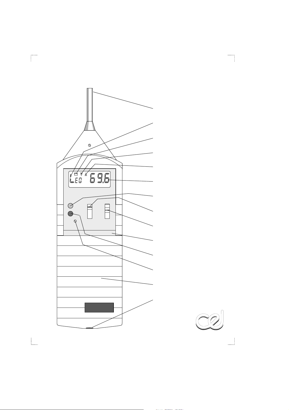
ELECTRET MICROPHONE
MODE INDICATOR
LOW BATTERY INDICATOR
OVERLOAD INDICATOR
UNDER RANGE INDICATOR
060114
Issue: 4
September1999
DIGITAL INTEGRATING
SOUND LEVEL METER
MODE
CAL
dB
RANGERESET
RESPONSE
AHI
OFF
F
ALO
S
CLO
I
CHI
HI=65-135dB(A)
LO=30-100dB(A)
CEL-269
DISPLAY
RESET BUTTON
(CURRENT FUNCTION)
RANGE SWITCH
RESPONSE/POWER SWITCH
RETAINING CLIP (2)
MODE BUTTON
CALIBRATION CONTROL
COLOURED COVER
STANDARD 3.5mm 3 POLE
COAXIAL OUTPUT SOCKET
(NOT FOR POWER)
990016
CEL-269 Digital Integrating Sound Level Meter
Instructions
INTRODUCTION
The CEL-269 Digital Integrating Impulse Sound
Level Meter has been designed to meet the
measurement requirements of Safety Engineers,
Occupational Nurses, Industrial Safety Officers,
and other specialists who require inexpensive and
easily used instrumentation to determine whether
industrial noise exposure areas require a more
detailed investigation.
The instrument features an eight-bit micro-
processor that calculates the time averaged levels
continuously. L
level) represents the steady continuous level
which would have the same energy content as
the varying noise level being measured. It is
obtained by integrating sound pressure levels
with respect to time according to:
=10log
L
eq
Where P is the instantaneous sound pressure, P
the reference pressure 2 x 10⁻⁵Pa, and T the
measurement duration.
The microprocessor also calculates the time
constants required for measuring with the
standard time weightings: Fast, Slow, and
Impulse (with reset function), and there is a
maximum hold mode that operates with all time
constants.
The instrument satisfies the requirements of IEC
651 Type 2, BS 5969 Type 2, and ANSI S1.4 Type
2A standards for both free field and random
incidence sound level meters, IEC 651 Type 2Ifor
impulse sound level meters, and IEC 804, BS
6698 for integrating sound level meters.
(the equivalent continuous noise
eq
T
1
P
)2dt
(
∫
T
P
0
0
A complete "CEL-269 Digital Integrating Impulse
Sound Level Meter" consists of the following
items.
CEL-269 Sound Level Meter,
32460 Microphone Cover,
16022 Type AAA Manganese
38055 Screwdriver,
60114 Instructions.
The following accessories may be ordered
separately to enable the user to gain the
maximum advantage from the instrument.
CEL-4672/2Windshield,
CEL-5894 Case for measuring kit,
CEL-284/2 Acoustical Calibrator Class 1
CEL-282 Acoustical Calibrator Class 2
0
C4963/2 Tape Recorder Cable (2 m) with
Alkaline Battery (4 off),
(complete with CEL-4725
Microphone Coupler),
(complete with CEL-4725
Microphone Coupler),
3.5 mm jack plug & BNC plug for a.c
output.
PREPARATION FOR USE
Install four type AAA Manganese Alkaline
batteries and the instrument is ready for use. Zinc
carbon batteries are NOT suitable.
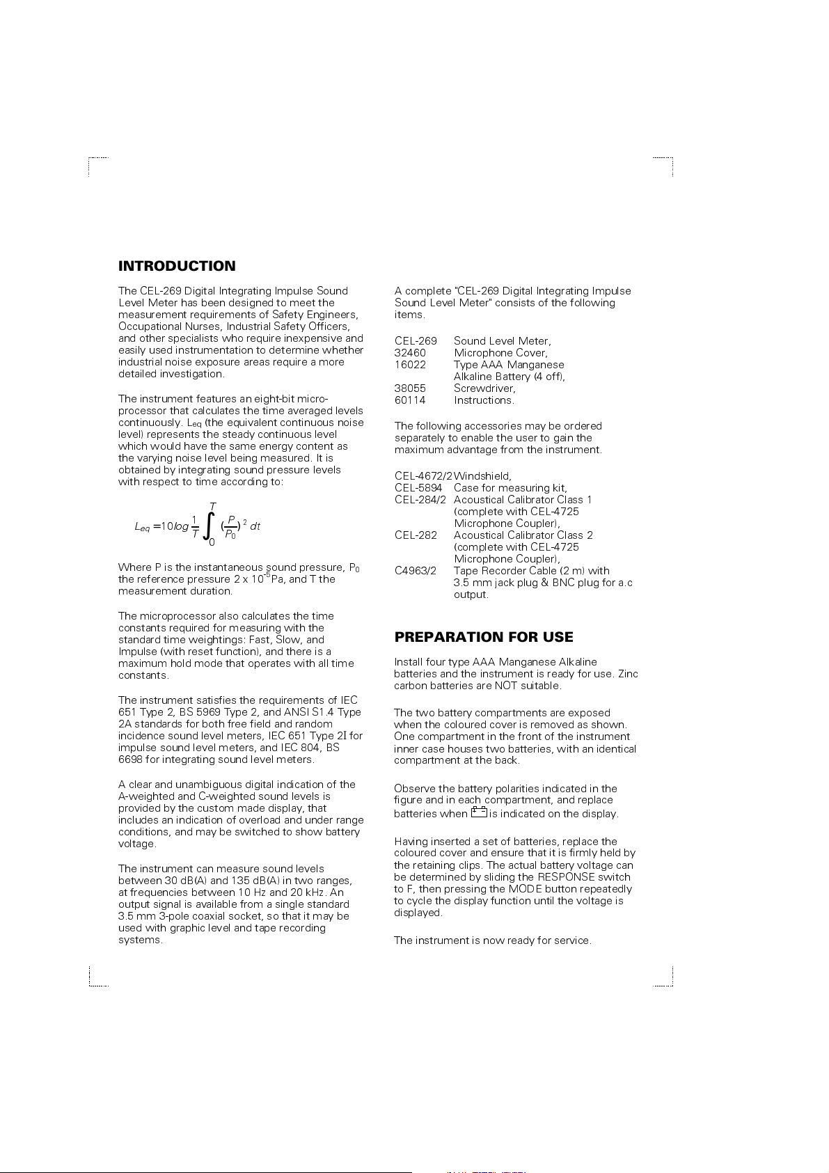
The two battery compartments are exposed
when the coloured cover is removed as shown.
One compartment in the front of the instrument
inner case houses two batteries, with an identical
compartment at the back.
A clear and unambiguous digital indication of the
A-weighted and C-weighted sound levels is
provided by the custom made display, that
includes an indication of overload and under range
conditions, and may be switched to show battery
voltage.
The instrument can measure sound levels
between 30 dB(A) and 135 dB(A) in two ranges,
at frequencies between 10 Hz and 20 kHz. An
output signal is available from a single standard
3.5 mm 3-pole coaxial socket, so that it may be
used with graphic level and tape recording
systems.
Observe the battery polarities indicated in the
figure and in each compartment, and replace
batteries when is indicated on the display.
Having inserted a set of batteries, replace the
coloured cover and ensure that it is firmly held by
the retaining clips. The actual battery voltage can
be determined by sliding the RESPONSE switch
to F, then pressing the MODE button repeatedly
to cycle the display function until the voltage is
displayed.
The instrument is now ready for service.
Gain access to the TWO battery
compartments:
1
2
1
Squeezethelightcolouredclipsas
shownatarrows1.Thenslidethecoloured
coveroffinthedirectionofarrow2.
There are TWO battery compartments
2 Batteries
inFront
Compartment
Load2batteriesintoeach
compartment,followingthe
batterypolaritiesshownhere.
(Alsoshowninsidethecompartment)
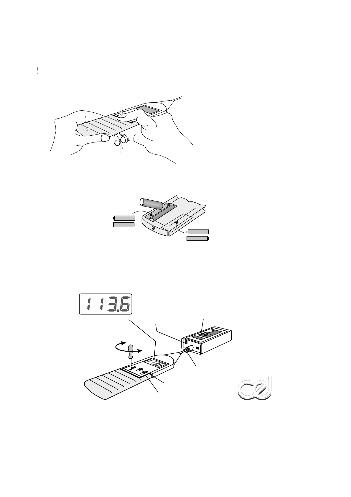
Presstheswitch
heretoswitchthe
calibratoron
990017
2 Batteries
inRear
Compartment
990018
Positionthecalibratorwith
itslabeluppermostsothat
bothcalibratorandmeter
canlayonaflatsurface
Rotatethe
screwdriver
toadjust
calibration
level
Calibrator
MicrophoneCoupler
990019
Response"F"
Range"AHi"
 Loading...