

Calibration reference conditions:
Free field perpendicular incidence,
Ambient temperature: 20
o
C,
Relative humidity: 65%,
Measurement Range: Hi (high),
Excitation SPL: 114 dB,
Frequency: 1 kHz.
Effect of humidity on accuracy:
Less than±0.5dB over the range 30 to 90%
RH (provided there is no condensation),
relative to the value at 65% RH and 40
o
C.
Storage range: 20 to 95% RH
non-condensing.
Effect of temperature on accuracy:
Less than±0.5dB over range -10 to +40
For temperatures between +40 and +50
o
C.
o
C
it is recommended that the instrument be
recalibrated at the operating temperature
with a CEL-282 or CEL-284/2.
However above 40
limits of IEC 651 can be obtained using the
following correction, where t is
Corrected reading = display reading + 0.05(t-40).
Operating temperature range: -10 to +50
Storage range: -20 to + 60
o
C, accuracy within the
o
C:
o
C.
o
C.
Effect of magnetic fields on accuracy:
Negligible at all levels.
Lower than a reading of 30 dB(A) when
tested according to IEC 651 clause 8.4.
Effect of vibration on accuracy:
Less than 3 dB when tested according to
IEC 651 clause 8.3.
Directional response:
Within the limits of IEC 651.
Effect of operator:
Negligible when instrument held at arms
length with microphone pointing away from
operator.
Frequency weightings:
A-weighting according to ANSI S1.4 Type
2A, and IEC 651 Type 2.
C-weighting according to ANSI S1.4 Type
2A, and IEC-651 Type 2.
Time weightings:
F (fast): 125 milliseconds,
S (slow): 1 second,
I
(impulse): 35 millisecond rise time,
1.5 second decay time, with
MAX: Holds noise readings of
I
, with decay <1 dB /
F, S, &
5 minutes at temperatures
o
C.
Digital display:
1
/2digits,
3
<40
7 segments,
12.5 mm high characters,
0.1 dB resolution.
Display updated 3 times per second.
Functions indicated:
Sound level dB(A),
Low battery level. (Indicated when battery
falls below approximately 3.2 V).
Sound level dB(C),
Battery voltage (x10),
Overload,
Maximum SPL (A- or C-weighted).
Overload detection:
(CEL-254 Only)
Pre-weighting overload detector, with 2.5 s
dwell time.
Start up stabilisation time:
20 seconds.
Outputs:
Two outputs from standard 3 pole 3.5 mm
coaxial socket with a.c on pin, d.c on
intermediate, and ground on sleeve.
DC: Log. signal with nominal 25 mV/dB
(offset by approx. 4 to 5 V) and not
exceeding 6 V,
125 ms rise & decay times for Fast,
1 s rise time & decay time for Slow.
35 ms rise time and 1.5 s decay time
for Impulse.
Recommended impedance of load
>27 kΩ.
AC: Conditioned signal, 7.25 V RMS for
FSD,
Recommended impedance of load
>39 kΩ.
Batteries:
4 x IEC AAA Manganese Alkaline type.
Battery life is typically better than 20 hours
with continuous use.
Dimensions:
258 x 70 x 21 mm, (10 x 2.75 x 0.85 inches).
Weight:
200 g, (0.45 lb) excluding batteries.
quick reset.
CEL and Dawe Equivalent Identities
Instrument Class 1L
CEL Identity CEL-284/2 CEL-282 CEL-231 CEL-254 CEL-269 (Obs) CEL-272 (Obs)
Dawe Identity D-1418D D - 14 1 1 E D-1405E D-1422C D-14 2 1 D (Obs) D-142 3 D (Obs)
Calibrator
Class 2L
Calibrator
Digital Sound
Survey Meter
Digital
Impulse SLM
Digital
Integrating SLM
Personal Sound
Exposure Meter
Compliance
The CEL-231 and CEL-254 Sound Level
Meters comply with the EMC Directive
89/336/EEC of the European Union. They have
been tested according to the standard delivery
schedule and comply with the following
standards.
EN 50081-1: 1992 & EN 50081-2: 1993
Generic emission standards for residential,
commercial, light industry and industrial
environments.
EN 50082-1: 1992 & EN 50082-2: 1995
Generic immunity standards (for both RF fields
and electrostatic discharge) for residential,
commercial, light industry and industrial
environments.
Manufacturers Servicing & Warranty Arrangements
In order to ensure its rigid conformity with
the requirements of the specification, this
instrument is thoroughly inspected and
calibrated prior to dispatch from the factory. All
technical information for an individual
instrument is filed under the instrument serial
number. Therefore, the serial number should be
quoted in any correspondance concerning the
instrument.
The manufacturers undertake to rectify any
defect in the instrument that is directly
attributable to faulty design or assembly, and
which becomes apparent during the warranty
period. In order to take advantage of this
warranty, the instrument must be returned,
carriage paid, to the manufacturers factory or
accredited agent, where necessary repairs will
be carried out.
Normally, the warranty period runs for 12
months from the date of receipt of goods, with
exceptions on certain specialised components
supplied by other manufacturers which are
warranted for shorter periods. Some of the
specialised components used in this instrument
may be subject to longer guarantees by their
actual manufacturers, and in all such cases, the
benefit of these undertakings will be passed on
to the user. However, Casella CEL Ltds liability
is limited to items of their own manufacture,
and they do not accept liability for any loss
resulting from the operation or interpretation of
the results from this equipment.
CEL and Dawe instrumentation is designed, manufactured, and serviced by:
CASELLA CEL
Regent House, Wolseley Road, Kempston, Bedford, MK42 7JY, U.K
Telephone: +44 (0) 1234 844 100 Fax: +44 (0) 1234 841 490 e-mail; info@casella.co.uk
CASELLA CEL
Tech Park, 17 Old Nashua Road, Box 15, Amherst, NH 03031, U.S.A.
Office Phone: +1 603 672 0031 Toll Free: 1 800 366 2966 Fax: +1 603 672 8053
e-mail: us-sales@casella-cel.com
Think environment think Casella www.casella.co.uk
A comprehensive Instrument Calibration
Maintenance Agreement (ICMA) scheme is
available to extend the initial warranty period of
this instrument. At the end of the first warranty
period, it is recommended that the equipment
be returned to the Service and Re-calibration
Department at Bedford, where it will be
inspected and entered into the ICMA scheme
as required. The warranty will then be extended
for the period stated on the individual schedule.
Please contact your local Casella CEL agent for
full details of this service.
In the event of a malfunction developing
during the warranty period, the instrument
should be carefully packed and returned either
to Casella CELs local agent, or in the case of
domestic sales, to the Service Department at
Bedford.
Please include the following information:
Instrument Type(s) and Serial Number(s),
Customer name and address,
Contact name and phone number,
Reason for returning the equipment with a
detailed description of the fault.
The necessary adjustments or repairs will
be carried out, and the instrument returned as
soon as possible. After the warranty has expired
(except on approved accounts) service work is
undertaken against quotations, and all packing
and transit costs are charged extra.
DIGITAL IMPULSE SOUND LEVEL METER
RANGEMODE RESPONSE
AHI
ALO
CLO
CHI
CAL
SPL
MAX
BAT
CEL-254
01013
OFF
F
S
I
IR
HI= 65-135dB(A)
LO=30-100dB(A)
dB
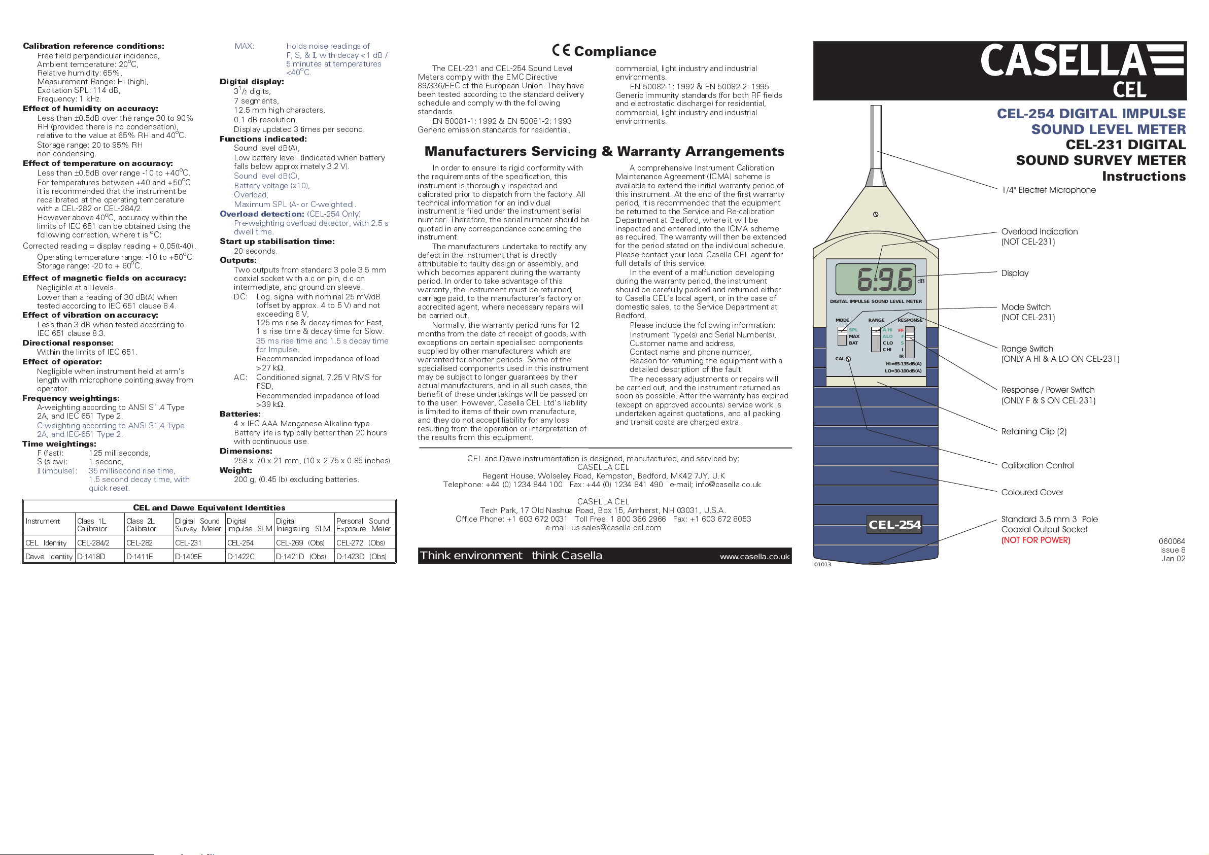
CEL-254 DIGITAL IMPULSE
SOUND LEVEL METER
CEL-231 DIGITAL
SOUND SURVEY METER
Instructions
1/4" Electret Microphone
Overload Indication
(NOT CEL-231)
Display
Mode Switch
(NOT CEL-231)
Range Switch
(ONLY A HI & A LO ON CEL-231)
Response / Power Switch
(ONLY F & S ON CEL-231)
Retaining Clip (2)
Calibration Control
Coloured Cover
Standard 3.5 mm 3- Pole
Coaxial Output Socket
(NOT FOR POWER)
060064
Issue 8
Jan 02
INTRODUCTION
The CEL-231 Digital Sound Survey Meter
has been designed to meet the sound survey
requirements of Safety Engineers and
Occupational Nurses, while the more powerful
CEL-254 Digital Impulse Sound Level Meter is
designed for Industrial Safety Officers.
These specialists require inexpensive and
easily used instruments to check whether
industrial noise exposure areas require a more
detailed investigation.
Both instruments satisfiy the requirements
of the international and national IEC 651 Type 2,
BS EN 60651 : 1994 Type 2, and ANSI S1.4
Type 2A standards for both free field and
random incidence sound level meters. The
CEL-254 also satisfies the requirements of IEC
651 Type 2Ifor impulse sound level meters.
The instruments provide a clear and
unambiguous digital indication of the
A-weighted sound level on an easily read
display. They feature the standard Fast and
Slow time weightings, and can measure sound
levels between 30 dB(A) and 135 dB(A) in two
ranges, at frequencies between 10 Hz and 20
kHz.
In addition, the CEL-254 can indicate
C-weighted sound levels and overload
conditions, includes a standard Impulse time
weighting with reset function, indicates battery
voltage on the display, and has a maximum hold
function that operates with all time constants.
Conditioned a.c, and logarithmic d.c outputs
are available from a single standard 3.5 mm 3
pole coaxial socket in both instruments, so they
may be used with level/time and tape recording
systems.
A complete CEL-231 Sound Survey Meter
consists of the following items.
CEL-231 Sound Survey Meter,
032460/DP Microphone Cover,
016022 (4 off) Type AAA Manganese
Alkaline Battery,
038055 Screwdriver,
060064/HB Instructions.
A complete CEL-254 Digital Impulse Sound
Level Meter consists of the following items.
CEL-254 Digital Impulse SLM,
032460/DP Microphone Cover,
016022 (4 off) Type AAA Manganese
Alkaline Battery,
038055 Screwdriver,
060064/HB Instructions.
The following accessories may be ordered
separately to enable the user to gain the
maximum advantage from the instrument.
CEL-284/2 Acoustical Calibrator Class 1L
(complete with CEL-4725
Microphone Coupler),
CEL-282 Acoustical Calibrator Class 2L
(complete with CEL-4725
Microphone Coupler),
C4963/2 Tape Recorder Cable (2 m)
with 3.5 mm jack plug & BNC
plug for a.c output,
C4964/2 Level Recorder Cable (2 m)
with 3.5 mm jack plug & BNC
plug for d.c output.
PREPARATION FOR USE
Install four type AAA Manganese Alkaline
batteries and the instrument is ready for use.
Zinc carbon batteries are NOT suitable.
The two battery compartments are exposed
when the coloured cover is removed as shown.
One compartment in the front of the instrument
inner case houses two batteries, with an
identical compartment at the back.
Observe the battery polarities indicated in
the figure and in each compartment, and
replace batteries when LO BAT is indicated.
Having inserted a set of batteries, replace the
coloured cover and ensure that it is firmly held
by the retaining clips.
On the CEL-254, the battery voltage (x10)
can be displayed by sliding the MODE switch to
BATT.
The instrument is now ready for operation.
CALIBRATION
Perform an acoustic calibration with a
CEL-282 or CEL-284/2 Acoustical Calibrator
immediately before and after measurement as
follows.
1. Remove the Microphone Cover.
2. Fit the CEL-4725 Microphone Coupler on to
the calibrator.
3. Push the calibrator and Coupler on to the
Microphone, with the label at the top as
shown.
4. Slide the Range switch to A HI (high range).
5. Slide the Response switch to F (fast) to switch
the instrument on.
On the CEL-254, also slide the MODE switch
to SPL (sound pressure level) for normal
noise measurement.
6. Wait 20 seconds for the instrument to
stabilise.
A LO BAT message indicates that the
batteries should be changed.
On the CEL-254, battery voltage (x10) can be
indicated on the display by sliding the
MODE switch to BATT.
7. Press the bottom of the calibrator switch to
obtain the nominal 114 dB at 1 kHz.
On instruments supplied after 1-1-96, the
meter display should read 113.6 dB while on
earlier instruments it should read 114.0 dB.
8. If necessary, carefully
adjust the CAL control
with the screwdriver
provided until the
indication is correct.
Two versions of the CAL
control are found.
One uses
9 dB of adjustment,
while the other has 4
turns for 12 dB.
9. Switch the calibrator OFF,
when not in use.
Other calibrators may be
used with the Sound Level
Meter, but the correct
indication will depend upon
the volume of the acoustic
coupler used, the operating
frequency, and the
calibration level.
Pistonphones are not
suitable because they
operate at low frequencies,
which produce incorrect
reading when measured
with A- or C-weighted
circuits.
It is recommended that
the calibration be verified at
at least every year. Contact
the CEL Service Department
for details.
OPERATION
1. Insert batteries as
described above.
2. Calibrate the instrument.
3. Switch the calibrator OFF.
4. Remove the calibrator and
microphone coupler.
5. Select A HI (high) Range
On the CEL-254, C HI
may also be selected.
These ranges cover sound levels between
65 and 135 dB.
6. Use F (fast response) for comparatively
stable noise, or select S (slow response) for
slowly varying noise.
On the CEL-254,
be selected for more rapidly varying and
impulsive noise.
Impulsive noises are captured and held on
the display as A- or C-weighted levels for
approximately 1.5 s.
Slide the RESPONSE switch to IR (impulse
reset) to clear the display for the next noise
measurement.
3
/4turn to give
I
(impulse response) may
01014
(4 x Type IEC AAA
Alkaline Batteries)
Turn
Screwdriver
01016
2
2 Batteries
CEL-254
1
1
(1) Gently squeeze the clips
(2) Then pull apart .
+
+
01015
2 Batteries
Switch
Microphone Coupler
Time WeightingF (Fast)
Range A Hi (or C Hi)
Measurement Mode SPL
7. Hold the instrument comfortably in the hand
and point the microphone at the suspected
noise source.
The sound level will be displayed.
8. Select A LO (low) range when the indicated
sound level falls below 80 dB(A).
On the CEL-254, C LO may also be selected.
If OVERLOAD is indicated on the CEL-254,
reselect one of the HI ranges.
9. On the CEL-254, slide the MODE switch to
MAX (maximum hold function) to capture
and hold maximum noise levels for longer
periods using any time weighting and range.
Calibrator
Slide the MODE switch to SPL to clear the
display for the next measurement.
10. Switch the instrument OFF (RESPONSE
switch to OFF) when not in use.
11. Remove batteries when out of service for
longer periods.
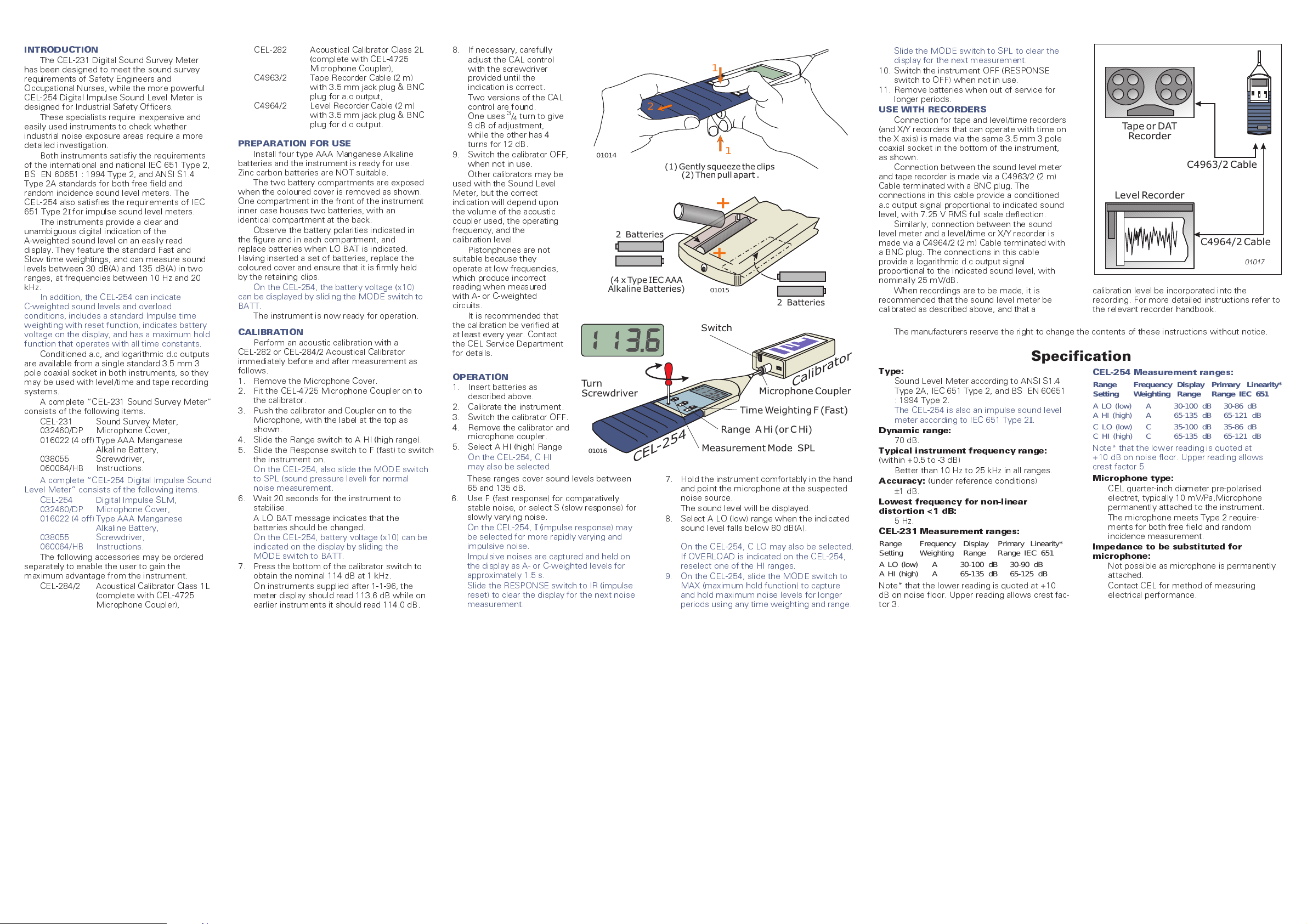
USE WITH RECORDERS
Connection for tape and level/time recorders
(and X/Y recorders that can operate with time on
the X axis) is made via the same 3.5 mm 3 pole
coaxial socket in the bottom of the instrument,
as shown.
Connection between the sound level meter
and tape recorder is made via a C4963/2 (2 m)
Cable terminated with a BNC plug. The
connections in this cable provide a conditioned
a.c output signal proportional to indicated sound
level, with 7.25 V RMS full scale deflection.
Similarly, connection between the sound
level meter and a level/time or X/Y recorder is
made via a C4964/2 (2 m) Cable terminated with
a BNC plug. The connections in this cable
provide a logarithmic d.c output signal
proportional to the indicated sound level, with
nominally 25 mV/dB.
When recordings are to be made, it is
recommended that the sound level meter be
calibrated as described above, and that a
The manufacturers reserve the right to change the contents of these instructions without notice.
Tape or DAT
Recorder
C4963/2 Cable
Level Recorder
C4964/2 Cable
calibration level be incorporated into the
recording. For more detailed instructions refer to
the relevant recorder handbook.
Specification
Type:
Sound Level Meter according to ANSI S1.4
Type 2A, IEC 651 Type 2, and BS EN 60651
: 1994 Type 2.
The CEL-254 is also an impulse sound level
meter according to IEC 651 Type 2
Dynamic range:
70 dB.
Typical instrument frequency range:
(within +0.5 to -3 dB)
Better than 10 Hz to 25 kHz in all ranges.
Accuracy:
±
Lowest frequency for non-linear
distortion <1 dB:
5 Hz.
CEL-231 Measurement ranges:
Range Frequency Display Primary Linearity*
Setting Weighting Range Range IEC 651
A LO (low) A 30-100 dB 30-90 dB
A HI (high) A 65-135 dB 65-125 dB
Note* that the lower reading is quoted at +10
dB on noise floor. Upper reading allows crest fac-
tor 3.
(under reference conditions)
1 dB.
I
.
CEL-254 Measurement ranges:
Range Frequency Display Primary Linearity*
Setting Weighting Range Range IEC 651
A LO (low) A 30-100 dB 30-86 dB
A HI (high) A 65-135 dB 65-121 dB
C LO (low) C 35-100 dB 35-86 dB
C HI (high) C 65-135 dB 65-121 dB
Note* that the lower reading is quoted at
+10 dB on noise floor. Upper reading allows
crest factor 5.
Microphone type:
CEL quarter-inch diameter pre-polarised
electret, typically 10 mV/Pa,Microphone
permanently attached to the instrument.
The microphone meets Type 2 require-
ments for both free field and random
incidence measurement.
Impedance to be substituted for
microphone:
Not possible as microphone is permanently
attached.
Contact CEL for method of measuring
electrical performance.
01017
 Loading...