


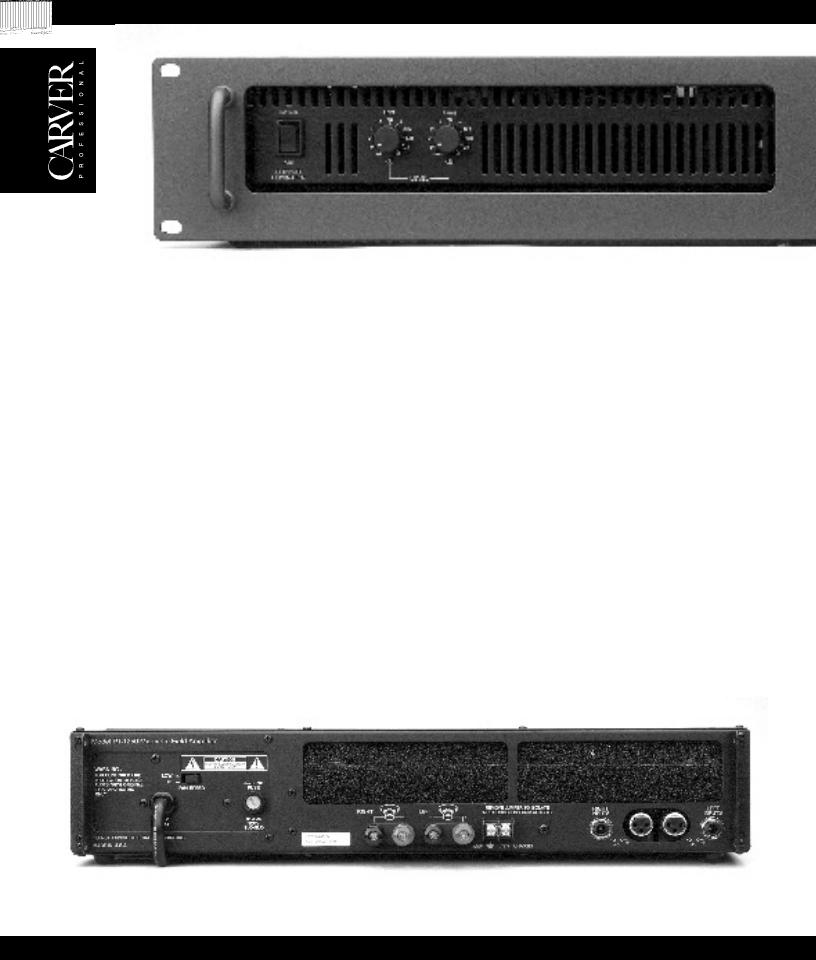
p t1 2 5 0 / p t1 8 0 0 / p t2 4 0 0
P ro fe s s io n a l S te re o P o w e r A m p lifie r

S af et y I n f o r mat io n
CAUTION
RISK OF ELECTRIC SHOCK
DO NOT OPEN
CAUTION: TO REDUCE THE RISK OF ELECTRIC SHOCK
DO NOT REMOVE COVER (OR BACK)
NO USER-SERVICEABLE PARTS INSIDE
REFER SERVICING TO QUALIFIED SERVICE PERSONNEL
The lightning flash with arrowhead symbol within an equilateral triangle is intended to alert the user to the presence of uninsulated "dangerous voltage" within the product's enclosure that may be of sufficient magnitude to constitute a risk of electric shock to persons.
The exclamation point within an equilateral triangle is intended to alert the user of the presence of important operating and maintenance (servicing) instructions in the literature accompanying the appliance.
Tabl e Of |
|
Introduction .......................................................... |
1 |
Unpacking and Paperwork ................................... |
1 |
Features and Specifications |
|
pt1250............................................................... |
2 |
pt1800............................................................... |
4 |
pt2400............................................................... |
6 |
Controls and Functions |
|
pt1250............................................................... |
8 |
pt1800/2400.................................................... |
10 |
Installation pt1250 |
|
Location and |
|
General Precautions........................................ |
12 |
Mechanical Considerations ............................ |
12 |
Rear Support for |
|
Road Applications .......................................... |
12 |
Thermal Considerations.................................. |
12 |
AC Power Considerations .............................. |
12 |
Magnetic Leakage |
|
Considerations................................................ |
12 |
Input Wiring.................................................... |
12 |
Output Wiring................................................. |
13 |
Polarity............................................................ |
13 |
70V Distribution Systems .............................. |
14 |
Clipping Eliminator........................................ |
14 |
Co n t en t s |
|
Installation pt1800/pt2400 |
|
Location and |
|
General Precautions........................................ |
14 |
Mechanical Considerations ............................ |
14 |
Rear Support for |
|
Road Applications .......................................... |
14 |
Thermal Considerations.................................. |
14 |
AC Power Considerations.............................. |
15 |
Magnetic Leakage |
|
Considerations................................................ |
15 |
Input Wiring.................................................... |
15 |
Output Wiring................................................. |
15 |
Polarity............................................................ |
16 |
Dual Mono...................................................... |
16 |
Bridged Mono................................................. |
16 |
70V Distribution Systems .............................. |
17 |
Clipping Eliminator........................................ |
17 |
Power ON Sequencing ................................... |
17 |
Remote Power Control................................... |
18 |
Operating Tips |
|
Using the pt1250/1800/2400.......................... |
19 |
In Case of Difficulty........................................... |
19 |
Care and Service Assistance............................... |
20 |
Warranty Information ......................................... |
21 |

I n t r o d u c t io n
Congratulations on your purchase of a new Carver Professional Power Amplifier. It is backed by state-of-the-art engineering and manufacturing techniques to bring you the best in quality craftsmanship and reliable performance. The pt1250, pt1800 and, pt2400 are specially designed for pro touring applications. Their rugged construction and low profile make it ideal for sustaining the abuses of the road with reliability and space-saving economy. The pt1250 is rated at 625 watts per
channel into 4 ohms and 465 watts per channel into 8 ohms. The pt1800 is rated at 900 watts per channel into 4 ohms and 600 watts per channel into 8 ohms. The pt2400 is rated at 1200 watts per channel into 4 ohms and 750 watts per channel into 8 ohms. The sophisticated protection circuits designed into this amplifier will protect your system should an unexpected fault occur. They also protect the amplifier from excessive temperature, continuous current limiting and shorted outputs. The balanced input uses a high quality, high common-mode rejection differential amplifier for exceptional hum and noise rejection. The sequencing feature on the pt1800 and pt2400 allows a rack of amplifiers to be powered up from a remote location. The daisy-chain connection scheme causes each amplifier to turn on in sequence, preventing the large in-rush current that can occur when an entire rack of amplifiers is turned on simultaneously. This power amplifier was designed and manufactured by people with a lifetime commitment to providing the world’s finest components for music and sound reproduction. Thanks for placing your confidence in Carver Professional. We know your amplifier will provide many years of dependable service and reliable sound reproduction.
U n pac k in g an d
Paper wo r k
Carefully unpack the amplifier and keep the original carton and packing materials for future moving, shipment or long-term storage. After opening the box, please check for any visible signs of damage that were not apparent from the outside of the box. If you do encounter what appears to be concealed damage, please consult your Carver Professional Dealer before installing the unit.
Important Paperwork
Make sure to save your sales receipt. Your receipt is extremely important to establish the duration of your Limited Warranty, and for insurance purposes. Next, make a note of the serial number which is located on the back of the amplifier. Record it in the space provided below for convenient reference.
Model:________ pt1250 ________ pt1800 ________ pt2400
Serial Number:___________________
Purchased at:_____________________
Date:___________________________
Finally, take a moment to fill out and return the Warranty Registration Card packed with the amplifier and return it to Carver Professional. This will allow us to keep you informed about new products as they become available.
1
pt 12 5 0
features
●465W per channel into 8 ohms
625W per channel into 4 ohms
●XLR and 1/4” TRS input connectors
●Accepts balanced or unbalanced lines
●Heavy-duty 5-way speaker binding posts
●Independent CH 1 and CH 2 Level Controls with 11 detented positions
●Internally configurable for Parallel Mono mode for single channel low impedance operation
●Highly efficient Pulse Width Modulated (PWM) power supply
●High-efficiency linear tracking output design
●Dual-stage slow power-up
●High power to weight ratio (1250 watts/11 pounds)
●Independent CH 1/CH 2 protection circuits will
instantaneously activate if one of the following fault conditions is detected:
Excessive High Frequency
Over Temperature
Short Circuit
D.C. Offset
●Additional protection circuitry includes: Clipping Eliminator
AC Line Fuse
●Power Connected/Standby indicator
●7 LED display per channel, including Power Ready and Clip/Protect indicators
●2-speed switchable Fan cooled
●70-volt stereo direct drive operation
2

• features
Continuous Average Output Power, both channels driven:
465 watts per channel into 8 ohms from 20Hz to 20kHz, with no more than 0.5% THD; 625 watts per channel into 4 ohms from 20Hz to 20kHz, with no more than 0.5% THD
Parallel-mono operation:
100 watts into 4 ohms from 20Hz to 20kHz, with no more than 0.5% THD 70-volt stereo: 600 watts per channel
70-volt parallel mono:
750 watts
Frequency Response:
20Hz to 20kHz (±0, -0.5 dB)
Damping Factor: >200
Input Impedance: 15 kilohms unbalanced,
|
each leg to ground 30 |
|
kilohms balanced |
Sensitivity: |
1.5 Vrms for rated power |
|
into 4 ohms |
Gain: |
32 dB (± 0.5 dB) |
Input Overload: |
+15 dBu |
THD: |
<0.5% |
IM Distortion: |
<0.1% |
|
|
||
Signal-to-Noise Ratio: |
|
|
|
>105dB, weighted, ref. to |
|
|
rated power into 4 ohms |
|
Slew Rate: |
25V / µS |
|
CMRR: |
>70dB @1kHz |
|
Power Consumption: |
|
|
|
1200W full power |
|
Power Requirements: |
|
|
|
120V AC / 60Hz (USA and |
|
|
Canada) Other voltages |
|
|
as required for export |
|
Fusing: |
10 amp slo-blo |
|
|
(120V/ 60Hz)5 amp |
|
|
slo-blo (230V / 50Hz) |
|
Display: |
7 LED indicators per |
|
|
channel 1 green READY, |
|
|
5 yellow SIGNAL, 1 red |
|
|
CLIP / PROTECT |
|
Size (H x W x D): |
3.50Ó (2U) x 19Ó x 10.25Ó |
|
|
89mm x 483mm x 273mm |
|
Net Weight: |
11 lbs. (5.0kgs) |
|
Shipping Weight: |
15lbs. (6.8kgs) |
|
Due to ongoing research and development, all specifications and features effective 4/96 are subject to change without notice.
3

features
pt 18 0 0
● Lightweight46 lbs. |
Thermal |
● Fully modular dual monaural design |
Clipping eliminator |
(from power switch to AC line cord). |
DC offset |
● High efficiency (50% input to output). |
Soft start/Input mute |
● Positive locking detachable dual AC line cords. |
● Separate L/R AC line fuses |
● Compact - only 12.75” deep. |
● Controls |
● Rugged, quiet, 100 CFM thermally controlled |
Dual power switches |
cooling system. |
Dual sequence switches |
● Compression circuit for long term excessive high |
Dual 11 detent level controls |
frequency signals. |
XLR phasing switch |
● Remote sequential power on/off feature. |
Series mono switch |
● Clipping eliminator circuit. |
Dual mono switch |
● Protection Features: |
Clipping eliminator switch |
Short circuit |
Ground lift |
Excessive high frequency |
● CSA, CE approved |
4

Power Output:
Both channels: driven (20Hz-20kHz)
8 ohm/ch. |
600 watts |
4 ohm/ch. |
900 watts |
2 ohm/ch. |
1100 watt |
Power Output: Series mono operation
|
(20Hz-20kHz) |
8 ohm |
1800 watts |
4 ohm |
2200 watts |
Signal to Noise Ratio:
>100dB
(from rated power @4Ω/A weighted)
Frequency Response:
20Hz to 20kHz ±0.5dB
Channel Seperation: >55db @1kHz
Slew Rate: |
25V/µs |
THD: |
4Ω 20-20kHz |
|
(at 900W) < 0.5% |
IM Distortion: |
<0.1% |
Damping Factor: |
>200 @1kHz |
Sensitivity: |
1.5 V rms |
Gain: |
32dB |
Input Impedance: 15 Kilohms
Unbalanced
30 Kilohms
Balanced
CMRR: |
>70db @1kHz |
|
|
||
Maximum Current Draw: |
|
|
|
30 A (4Ω |
|
|
rated power) |
|
Display: |
7 LED indicators per |
|
|
channel, 1 green on, |
|
|
5 yellow signal, 1 red |
|
|
clip/protect |
|
Cooling: |
Rear to front w/100 |
|
|
CFM maximum |
|
Connections- |
|
|
Input: |
XLR, barrier strip |
|
Output: |
5 way binding posts, |
|
|
2 sets/channel |
|
Size (HxWxD): |
5.25Ó (3u) x 19Ó x |
|
|
12.75Ó (133mm x |
|
|
483mm x 324mm) |
|
Net Weight: |
46lbs. (20.9 Kgs.) |
|
Shipping Wt.: |
55lbs. (25 Kgs.) |
|
Due to ongoing research and development, all specifications and features effective 4/96 are subject to change without notice.
5

features
pt 2 4 0 0
● Lightweight48 lbs. |
Thermal |
● Fully modular dual monaural design |
Clipping eliminator |
(from power switch to AC line cord). |
DC offset |
● High efficiency (50% input to output). |
Soft start/Input mute |
● Positive locking detachable dual AC line cords. |
● Separate L/R AC line fuses |
● Compact - only 12.75” deep. |
● Controls |
● Rugged, quiet, 100 CFM thermally controlled |
Dual power switches |
cooling system. |
Dual sequence switches |
● Compression circuit for long term excessive high |
Dual 11 detent level controls |
frequency signals. |
XLR phasing switch |
● Remote sequential power on/off feature. |
Series mono switch |
● Clipping eliminator circuit. |
Dual mono switch |
● Protection Features: |
Clipping eliminator switch |
Short circuit |
Ground lift |
Excessive high frequency |
● CSA, CE approved |
6
 Loading...