


pm125/pm420
Professional Stereo Power Amplifier
Safety Information
CAUTION
RISK OF ELECTRIC SHOCK
DO NOT OPEN
CAUTION: TO REDUCE THE RISK OF ELECTRIC SHOCK
DO NOT REMOVE COVER (OR BACK)
NO USER-SERVICEABLE PARTS INSIDE
REFER SERVICING TO QUALIFIED SERVICE PERSONNEL
The lightning flash with arrowhead symbol within an equilateral triangle is intended to alert the user to the presence of uninsulated "dangerous voltage" within the product's enclosure, that may be of sufficient magnitude to constitute a risk of electric shock to persons.
The exclamation point within an equilateral triangle is intended to alert the user of the presence of important operating and maintenance (servicing) instructions in the literature accompanying the appliance.
Table Of Contents
Introduction ............................................................ |
1 |
Unpacking and Paperwork ..................................... |
1 |
Features and Specifications |
|
pm125................................................................. |
2 |
pm420................................................................. |
4 |
Controls and Functions........................................... |
6 |
Installation |
|
Location and |
|
General Precautions............................................ |
8 |
Mechanical Considerations ................................ |
8 |
Rear Support for |
|
Road Applications .............................................. |
8 |
Thermal Considerations...................................... |
8 |
AC Power Considerations.................................. |
9 |
Magnetic Leakage |
|
Considerations.................................................... |
9 |
Installation (continued) |
|
Input Wiring........................................................ |
9 |
Input Sensitivity................................................ |
10 |
Output Wiring................................................... |
10 |
Polarity.............................................................. |
10 |
Dual Mono........................................................ |
10 |
Bridged Mono................................................... |
11 |
Parallel Mono ................................................... |
11 |
Clipping Eliminator.......................................... |
11 |
Operating Tips |
|
Using the pm125/pm420.................................. |
12 |
Servicing Instructions........................................... |
13 |
In Case of Difficulty............................................. |
14 |
Care and Service Assistance................................. |
15 |
Warranty Information ........................................... |
16 |

Introduction
Congratulations on your purchase of a new Carver Professional Power Amplifier. It is backed by state-of-the-art engineering and manufacturing techniques to bring you the best in quality craftsmanship and reliable performance. The pm125 and pm420 are specially designed for pro sound applications. Their rugged construction and low profile make them ideal for sustaining the abuses of the road with reliability and space-saving economy. And their accurate sound and
ample power make them ideal for critical studio applications as well. The pm125 is rated at 62 watts per channel into 4 ohms and 50 watts per channel into 8 ohms. In bridged mono operation it is rated at 125 watts into 8 ohms. The pm420 is rated at 210 watts per channel into 4 ohms and 135 watts per channel into 8 ohms. In bridged mono operation it is rated at 420 watts into 8 ohms. The sophisticated protection circuits designed into these amplifiers will protect your system should an unexpected fault occur. They also protect the amplifiers from excessive temperature, continuous current limiting and shorted outputs. The balanced input uses a high quality, high common-mode rejection differential amplifier for exceptional hum and noise rejection. These power amplifiers were designed and manufactured by people with a lifetime commitment to providing the world’s finest components for music and sound reproduction. Thanks for placing your confidence in Carver Professional. We know your amplifier will provide many years of dependable service and reliable sound reproduction.
Unpacking and
Paperwork
Carefully unpack the amplifier and keep the original carton and packing materials for future moving, shipment or long-term storage. After opening the box, please check for any visible signs of damage that were not apparent from the outside of the box. If you do encounter what appears to be concealed damage, please consult your Carver Professional Dealer before installing the unit.
Important Paperwork
Make sure to save your sales receipt. Your receipt is extremely important to establish the duration of your Limited Warranty and for insurance purposes. Next, make a note of the serial number which is located on the back of the amplifier. Record it in the space provided below for convenient reference.
Model_________ pm125_______ pm420
Serial Number: _____________________
Purchased at: ______________________
Date: _____________________________
Finally, take a moment to fill out and return the Warranty Registration Card packed with the amplifier and return it to Carver Professional. This will allow us to keep you informed about new products as they become available.
5
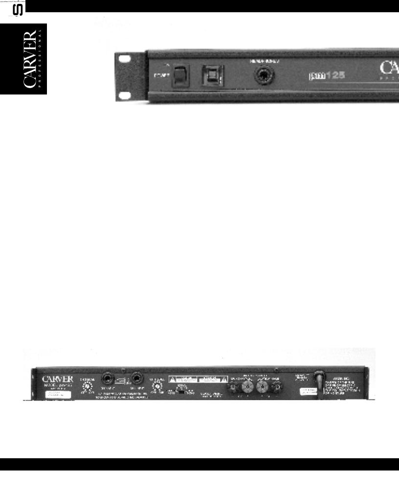
pm125
•50W per channel into 8 ohms
62W per channel into 4 ohms
125W mono into 8 ohms
•1/4-inch TRS input jacks
•Accepts balanced or unbalanced lines
•Multi-way binding post output connectors
•Independent 11 detent Level Controls for CH1 & CH2
•Dual Mono mode for operating both channels with a mono signal
•Bridged Mono mode for combining the power of both channels into a single higher-powered channel
•Input sensitivity set at 1.5V RMS from factory. Internally reconfigurable to 0.775V RMS.
•Internal jumpers to bypass Left and Right Channel Level Controls
•Independent CH1 / CH2 speaker relays will instantaneously disconnect if one of the following
fault conditions is detected: D.C. Offset
Over Temperature Short Circuit
•Additional protection circuitry includes:
Clipping Eliminator
Resettable Circuit Breaker
•Power Ready, Signal Present and Clip / Protect indicators for each channel
•Headphone jack
•Convection cooled
•70V transformer option
•CE 1997 approved
6

Continuous Average Output Power, both channels driven:
50 watts per channel into
8 ohms at 1kHz, with no more than 0.1% THD
62 watts per channel into
4 ohms at 1kHz, with no more than 0.1% THD
Bridged-mono operation:
125 watts into 8 ohms at 1kHz, with no more than 0.1% THD
Dynamic Headroom:
>2dB
Frequency Response:
20Hz to 20kHz (±0.75dB)
Channel Separation:
>55dB @ 1kHz
Damping Factor: <400
Input Impedance: 22 Kohms unbalanced, 44 Kohms balanced
Sensitivity: Low: 1.5VRMS for rated power into 4 ohms at 1kHz, 193mVRMS for 1W into 4 ohms @ 1kHz
High: 0.775VRMS for rated power into 4 ohms @ 1kHz, 100mVRMS for 1W
Signal-to-Noise Ratio:
>100dB, A-weighted, referenced to rated power into 4 ohms
Headphone Output:
3.0V
|
|
|
|
RMS into 60Ω |
|
|
(150mW) 11.3VRMS into |
|
|
600Ω (213mW) |
|
Slew Rate: |
>10V/µS |
|
CMRR: |
>40dB @ 1kHz |
|
Power Consumption: |
||
|
250W at full power into 4 |
|
|
ohms (continuous) |
|
Power Requirements: |
||
|
120VAC/60Hz (USA and |
|
|
Canada) Other voltages |
|
|
as required for export |
|
Display: |
3 LED indicators per |
|
|
channel: READY, SIGNAL, |
|
|
CLIP/PROTECT |
|
Size (H x W x D): |
1.75˝ (1U) x 19˝ x 13.25˝ |
|
|
44mm x 483mm x 337mm |
|
Net Weight: |
13.8 lbs. (6.3 kgs) |
|
Shipping Weight: |
17 lbs. (7.73 kgs) |
|
Due to ongoing continuous product development
features, specifications, and availability are subject
to change without notice.
7

pm420
•135W per channel into 8 ohms
210W per channel into 4 ohms
420W mono into 8 ohms
•1/4-inch TRS input jacks
•Accepts balanced or unbalanced lines
•Multi-way binding post outputs
•Independent 11 detent Level Controls for CH1 & CH2
•Dual Mono mode for operating both channels with a mono signal
•Bridged Mono mode for combining the power of both channels into a single higher-powered channel
•Input sensitivity set at 1.5V RMS from factory. Internally reconfigurable to 0.775V RMS.
•Internal jumpers to bypass Left and Right Channel Level Controls
•Independent CH1 / CH2 2 Speaker relays will instantaneously disconnect if one of the following
fault conditions is detected: D.C. Offset
Over Temperature Short Circuit
•Additional protection circuitry includes:
Clipping Eliminator
Resettable Circuit Breaker
•Power Ready, Signal Present and Clip / Protect indicators for each channel
•Convection cooled
•70V transformer option
•CE 1997 approved
8
 Loading...