


Carson Manufacturing Co., Inc.
5451 North Rural Street
Indianapolis, IN 46220
Phone: (888) 577-6877 Fax: (317) 254-2667
www.carsonsirens.com
TECHNICAL BULLETIN
M |
MECH |
|
A |
||
N |
WAIL |
|
A |
||
|
||
U |
|
|
T |
YELP |
|
O |
|
OUTPUT |
LT1 |
LT2 |
|
|
|
||
PHSR |
HORN |
|
|
SC-1002 |
|
|
|
|
|
SC-1012 |
|
|
MAN |
MECH |
PHSR |
LT1 |
LT2 |
S |
W |
|
|
|
T |
A |
|
|
|
B |
I |
|
|
|
Y |
L |
|
|
|
AUTO |
YELP |
HORN |
|
|
REMOTE PANEL |
OUTPUT |
POWER |
|
|
|
|
|
||
|
|
|
|
HAND |
LT2 LT1 HORN PHSR MECH YELP MAN AUTO LAMP NEG |
|
|
CONTROL |
|
|
|
|
||
SC-1000
SC-1022
MAN HORN
MECH WAIL
YELP PHSR
LT1 LT2
INSTALLATION AND
OPERATING MANUAL
SC-1002 / 1012 / 1022-10 14V
(Old Version)
Different DIP Switch Options
Carson is a trademark of Carson Manufacturing Company, Inc.
Sound Hazard - Sound level from siren speaker (>120dBA @ 10 feet) may cause hearing damage. Do not operate siren without adequate hearing protection for you and anyone in immediate vicinity. (Ref. OSHA 1910.95 for occupational noise exposure guidelines)
TB0362A |
Page 1 of 14 |
05/28/10 |
|
SC-1000 / 1012 / 1022-10 SPECIFICATIONS |
|
AMPLIFIER INPUT POWER: 9-16 Volts DC, 8 Amps DC |
||
SIREN MODE |
|
|
OUTPUT POWER: |
105 Watts RMS (15 VDC input, 100W speaker) |
|
SIREN |
|
|
FREQUENCY: |
700Hz - 1500Hz Nominal |
|
CYCLE RATES: |
MECHANICAL - 5 cycles/min |
|
|
WAIL - 13 cycles/min |
|
|
YELP - 190 cycles/min |
|
|
PHASER - 15 cycles/sec |
|
OPERATING |
TWO-TONE - 1 cycle/sec |
|
|
|
|
TEMPERATURE: |
-15° F to +140° F |
|
SIZE: |
SC-10XX Amplifier 6" Wide X 2" High X 6" Deep |
|
|
SC-1012 Control Head 4-1/2" Wide X 2" High X 1-3/4" Deep |
|
|
SC-1022 Control Head 1-7/8" Wide X 4" High X 1" Deep |
|
WEIGHT: |
3.5 pounds |
|
NIGHT VISIBILITY: |
SC-1002 |
Backlit front control panel when power is on |
|
SC-1012 |
Light control switches illuminate when turned on |
|
SC-1022 |
Backlit front control panel when power is on |
AMPLIFIER PROTECTION: |
High Voltage – Siren output stops with input voltage above highest rating |
|
Stops high output power from blowing speaker |
|
Reverse Polarity – Fuse blows when power is wired backwards |
|
Shorted Output – Fuse blows if speaker shorts (a common problem) |
LIGHT CONTROL INPUT POWER: |
10-16 Volts DC, 20 Amps Max. not including siren input current |
TWO LIGHT CONTROL OUTPUTS: |
20 Amps Max. per circuit, 20Amps Max. Total |
LIGHT C0NTROL PROTECTION: |
Shorted Output – Fuse blows |
NOTICE
Due to continuous product improvements, we must reserve the right to change any specifications and information, contained in this manual at any time without notice.
Carson Manufacturing Co., Inc. makes no warranty of any kind with regard to this manual, including, but not limited to, the implied warranties of merchantability and fitness for a particular purpose.
Carson Manufacturing Co., Inc. shall not be liable for errors contained herein or for incidental or consequential damages in connection with the furnishing, performance, or use of this manual.
See www.carsonsirens.com for latest information.
TB0362A |
Page 2 of 14 |
05/28/10 |
INSTALLATION
Proper installation of the unit is essential for years of safe, reliable operation. Please read all instruction before installing the unit. Failure to follow these instructions can cause serious damage to the unit or vehicle and may void warranties.
SAFETY PRECAUTIONS
For the safety of the installer, vehicle operator, passengers and the community please observe the following safety precautions. Failure to follow all safety precautions and instructions may result in property damage, injury or death.
Qualifications - The installer must have a firm knowledge of basic electricity, vehicle electrical systems and emergency equipment.
Sound Hazard - Sound level from siren speaker (>120dBA @ 10 feet) may cause hearing damage. Do not operate siren without adequate hearing protection for you and anyone in immediate vicinity. (Ref. OSHA 1910.95 for occupational noise exposure guidelines)
Mounting - Mount the unit for easy access by the vehicle operator. DO NOT mount in air bag deployment area. Assure clearances before drilling in vehicle.
Wiring - Use wiring capable of handling the current required. Make sure all connections are tight. Route wiring to prevent wear, overheating and interference with air bag deployment. Install and check all wiring before connection to vehicle battery.
Testing - Test all siren functions after installation to assure proper operation. Test vehicle operation to assure no damage to vehicle.
Keep These Instructions - Keep these instructions in the vehicle or other safe place for future reference. Advise the vehicle operator of the location.
MOUNTING (Main unit)
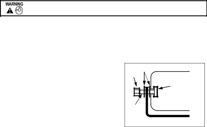
The mounting bracket supplied can be installed above or below the unit. Mounting bolts (standard 1/4-20) slide into channels on each side of the case. Lockwashers should be used between the case and bracket as well as between the bracket and nut. Choose a mounting location convenient to the operator and away from any air bag deployment areas. Inspect behind mounting area for clearance. Assure adequate ventilation to prevent overheating. Consider wire routing and access to connections. Install mounting bracket to vehicle using 1/4" hardware.
Lockwa shers
Nut
Channel |
(from rear) |
Bolt
Bracket
SC-1012 Remote Panel: The remote panel of the SC-1012 is typically mounted underneath the vehicle dashboard using mounting hardware. Mount the panel in a location away from the driver’s or passenger’s legs.
SC-1022 Hand Control: Choose a mounting location convenient to the operator and away from any air bag deployment areas. Consider cable routing to amplifier.
TB0362A |
Page 3 of 14 |
05/28/10 |
INSTALLER-SELECTABLE OPTIONS
An internal 8-position DIP switch on the circuit board may be changed to select various options.
Accessing Option Switches - the DIP switch is located just behind the front panel of the amplifier. Use a 7/64” allen wrench to remove the 4 corner screws then remove front panel.
Adjusting Option Switches - it is easiest to view the DIP switch with the unit turned upside down. With the unit upside down, the DIP Switch is located on the internal PCB assembly board toward the front center of the unit. Switch ‘ON’ position is toward the inside of the unit.
SW-1 (AUX_P) Auxiliary Input Polarity - The auxiliary input is normally activated with positive. Turn this switch OFF for negative activation.
SW-2 (INST_ON) Instant ON - The Enable input wiring is normally required to turn on the unit. Turn this switch ON to allow the front panel switches to instantly turn on the unit.
(SC-1002 and SC-1012 only)
SW-3 (T-T) Two-Tone - Turn this switch ON to replace Phaser with Two-Tone.
SW-4 (H_I) Horn Inhibit - Turn this switch ON to disable Horn tone. Horn will be replaced with Yelp.
Siren Tone Disable - All siren tones may be disabled (except Manual, Wail, and Yelp) by turning ON both switches SW-3 and SW-4. Mechanical will be replaced with Wail. Phaser and Horn will be replaced with Yelp.
SW-5 (HRC) Horn Ring Cycler 2 (HRC2) - Turn this switch ON to enable this feature. Also connect the auxiliary input to the horn ring or other switch. While the siren is in standby, tap the horn ring to bring the unit out of standby into Mechanical tone. Repeatedly tapping the horn ring will cycle through Mechanical, Wail, Yelp, and Phaser tones. Tapping the horn ring twice quickly will stop the siren tones and return the unit to standby. Pressing and holding the horn ring will produce Horn tone until released. Then the siren will return to its previous siren tone or standby.
SW-4 (P_I) Phaser Inhibit - Turn this switch on to disable Phaser and Two-Tone.
SW-6 (SM) Short Manual - The Manual siren tone will normally fall and die out when released. Turn this switch ON to have Manual stop immediately.
SW-7 (MECH2) Mechanical Tone 2 - Turn this switch ON for a different mechanical tone sound. (less raspy)
SW-8 (FALL) Mechanical Fall - Turn this switch ON for a quicker mechanical tone fall time.
TB0362A |
Page 4 of 14 |
05/28/10 |
ELECTRICAL CONNECTIONS
Disconnect vehicle battery before making any electrical connections.
Electrical connections to the unit are made using a removable terminal block plug and screw terminals located on the amplifier. A label on the unit identifies each terminal function. Install the plug on the unit before wiring. If the unit needs service the plug can be easily removed without unwiring. The power supply of the unit must be capable of delivering peak currents up to 50 amps for adequate short circuit protection and reliable operation. The preferred source is directly at the vehicle battery. The amplifier is fused. Attach leads by stripping 3/8", inserting into plug and clamp by tightening screw. Make sure the screw is tight and the wire can’t be pulled out.
Failure to adequately tighten the screw can result in improper operation or burning the connector and wire.
Wire Size and Termination - The diagram shows the minimum wire size used for each connection, along with recommended lead color. If the wire is longer than 10 ft. use the next larger wire size. Use only high quality crimp connectors for installation on the vehicle.
Enable Input Connection (ORG lead on wiring diagram next page) - This is NOT the same as the main power connection. The enable input is like a power switch for the unit. When there is positive power at this connection, the unit is powered up and ready to function. When power is removed, the unit is not powered up and will not drain current from the battery. Connect to a positive circuit controlled by the vehicle ignition switch, usually a terminal at the vehicle fuse panel. The required current is low (15mA typ.).
For SC-1022:
The Enable Input must be connected.
For SC-1002 and SC-1012: The Enable Input is optional.
If it is not desired to wire the Enable Input, set the Instant ON DIP switch as described under INSTALLER SELECTABLE OPTIONS. The unit will instantly turn on when a switch on the face of the unit or the control panel is activated. This includes LT1 and LT2 switches. When all switches are deactivated, the unit will turn off. Without the enable input, the Manual siren tone will stop immediately. LT1 or LT2 switch may be used as power switch for the unit instead of Enable Input.
Auxiliary Input Connection (Optional) - A momentary input typically connected to the horn ring of the vehicle or other switch. See OPERATION section for auxiliary input functions.
NOTE: Permanent disconnection of the vehicle horn is NOT recommended.
The auxiliary input may be activated with positive or negative voltage. See Auxiliary Polarity under INSTALLER SELECTABLE OPTIONS section for proper activation polarity. Input current is 1 to 20 mA.
Aux Input for SC-1002 and SC-1012:
The unit must be turned on for the Auxiliary Input to function. This is accomplished with either the siren controls or Enable Input.
Instant ON option set and unit turned on with |
Unit turned on |
Auxiliary Input |
switch on face of unit or control panel. This includes LT1 or LT2. |
with enable input |
will Function |
NO |
NO |
NO |
YES |
NO |
YES |
NO |
YES |
YES |
YES |
YES |
YES |
TB0362A |
Page 5 of 14 |
05/28/10 |
 Loading...