


Carson Manufacturing Co., Inc.
5451 North Rural Street
Indianapolis, IN 46220
Phone: (888) 577-6877 Fax: (317) 254-2667
www.carsonsirens.com
TECHNICAL BULLETIN
RADIO |
|
PA |
|
|
SIREN |
||
HORN |
VOL |
||
|
|||
MAN |
|
|
|
WAIL |
ON |
|
|
YELP |
POWER |
||
PHASER |
|||
|
|
||
|
|
SA 430 |
|
INSTALLATION AND
OPERATING MANUAL
SA-430-73F (FLUSH MOUNT CONTROL HEAD) SA-430-73FX (FLUSH MOUNT WITH EXTENDED MIC) SA-430-73V (FLUSH MOUNT WITH VERTICAL LABEL)
Carson is a trademark of Carson Manufacturing Company, Inc.
Sound Hazard - Sound level from siren speaker (>120dBA @ 10 feet) may cause hearing damage. Do not operate siren without adequate hearing protection for you and anyone in immediate vicinity. (Ref. OSHA 1910.95 for occupational noise exposure guidelines)
TB0333B |
Page 1 of 10 |
10/18/03 |
|
SA-430-73 SPECIFICATIONS |
|
INPUT POWER: |
11-16 Volts DC, 8 Amps DC per 100W Speaker |
|
|
Power off current to amplifier is 25mA Max. |
|
SIREN MODE |
|
|
OUTPUT POWER: |
15 VDC input, 100W speaker(s) |
|
|
One speaker - 105 Watts RMS |
|
|
Two speakers - 180 Watts RMS |
|
|
Rating not available for 58W or 80W speakers |
|
AUDIO MODE |
|
|
OUTPUT POWER: |
14 VDC input, 100W speaker(s) |
|
|
One speaker - 40 Watts RMS |
|
|
Two speakers - 80 Watts RMS |
|
SIREN |
Rating not available for 58W or 80W speakers |
|
|
|
|
FREQUENCY: |
600Hz - 1350Hz Nominal |
|
CYCLE RATES: |
WAIL - 14 cycles/min |
|
|
YELP - 190 cycles/min |
|
AUDIO |
PHASER - 15 cycle/sec |
|
|
|
|
RESPONSE: |
200Hz - 10KHz +/-3db |
|
|
Harmonic Distortion Less than 3% @ 1KHz |
|
RADIO INPUT |
|
|
SENSITIVITY: |
0.75VAC Input Min. for 40 Watts RMS Output (1 spkr) |
|
OPERATING |
|
|
TEMPERATURE: |
-15° F to +140° F |
|
SIZE: |
Amplifier |
8-7/8" Wide X 1-13/16" High X 5-1/2" Deep |
|
Control Head |
6-1/4" Wide X 2-7/8" High X 1" Deep |
WEIGHT: |
Amplifier |
2.5 pounds |
|
Control Head |
1 pound |
NIGHT VISIBILITY: |
Control Head panel is backlit with independent lead tied to vehicle dash lights. |
AMPLIFIER PROTECTION: |
High Voltage – Siren output stops with input voltage above highest rating |
|
Stops high output power from blowing speaker |
|
Reverse Polarity - Fuse blows when power is wired backwards |
|
Shorted Output – Fuse blows if speaker shorts (a common problem) |
CONTROL HEAD PROTECTION: |
No fuse but has reverse polarity protection. |
NOTICE
Due to continuous product improvements, we must reserve the right to change any specifications and information, contained in this manual at any time without notice.
Carson Manufacturing Co., Inc. makes no warranty of any kind with regard to this manual, including, but not limited to, the implied warranties of merchantability and fitness for a particular purpose.
Carson Manufacturing Co., Inc. shall not be liable for errors contained herein or for incidental or consequential damages in connection with the furnishing, performance, or use of this manual.
TB0333B |
Page 2 of 10 |
10/18/03 |
INSTALLATION
Proper installation of the unit is essential for years of safe, reliable operation. Please read all instruction before installing the unit. Failure to follow these instructions can cause serious damage to the unit or vehicle and may void warranties.
SAFETY PRECAUTIONS
For the safety of the installer, vehicle operator, passengers and the community please observe the following safety precautions. Failure to follow all safety precautions and instructions may result in property damage, injury or death.
Qualifications - The installer must have a firm knowledge of basic electricity, vehicle electrical systems and emergency equipment.
Sound Hazard - Sound level from siren speaker (>120dBA @ 10 feet) may cause hearing damage. Do not operate siren without adequate hearing protection for you and anyone in immediate vicinity. (Ref. OSHA 1910.95 for occupational noise exposure guidelines)
Mounting - Mount the control head for easy access by the vehicle operator. DO NOT mount in air bag deployment area. Assure clearances before drilling in vehicle.
Wiring - Use wiring capable of handling the current required. Make sure all connections are tight. Route wiring to prevent wear, overheating and interference with air bag deployment. Install and check all wiring before connection to vehicle battery.
Testing - Test all siren functions after installation to assure proper operation. Test vehicle operation to assure no damage to vehicle.
Keep These Instructions - Keep these instructions in the vehicle or other safe place for future reference. Advise the vehicle operator of the location.
AMPLIFIER MOUNTING
Choose a mounting location in an area such as the driver compartment firewall, under a seat, etc. Mounting the amplifier in the engine compartment or in an area directly exposed to weather is not recommended. Assure adequate ventilation to prevent overheating. Consider wire routing and access to connector. Install amplifier to vehicle using 1/4" hardware (not supplied).
May need to set RADIO VOLUME ADJUST on side of amplifier before final mounting and installation. May also need to set POWER OUTPUT ADJUSTMENT on inside of amplifier.
CONTROL HEAD MOUNTING
Select a mounting location in an area such as the dash or overhead console. Choose a mounting location convenient to the operator and away from any air bag deployment areas. Consider wire routing and access to connections, as well as microphone bracket placement.
A microphone clip along with mounting screws (CP3633) holds the microphone in place.
FLUSH MOUNT
The flush mount control head requires a hole in the dash. Use the mounting template on the last page. Note that the template may not print actual size and may need sizing on a copier. Use #6 screws to fasten to dash.
FLUSH MOUNT WITH EXTENDED MICROPHONE
The flush mount control head with extended microphone is mounted the same as the flush mount except that the microphone cable extension will also go behind the dash. Allow room for this cable as well.
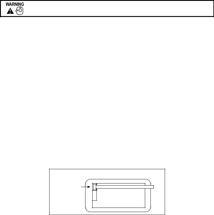
Control Head – Rear View
Microphone
Extension
Cable
TB0333B |
Page 3 of 10 |
10/18/03 |
 Loading...