


WEATHERMAKERTM TWO-SPEED 38TDB
Carrier WEATHERMAKERTM TWO-SPEED 38TDB, WeatherMaker 38TDB, WeatherMaker 38TDB037, WeatherMaker 38TDB024, WeatherMaker 38TDB036 Installation And Start-up Instructions Manual
...
Visit www.carrier.com
Installation and Start-Up Instructions
NOTE: Read the entire instruction manual before starting the
installation.
This symbol → indicates a change since the last issue.
SAFETY CONSIDERATIONS
Improper installation, adjustment, alteration, service, maintenance,
or use can cause explosion, fire, electrical shock, or other
conditions which may cause death, personal injury, or property
damage. Consult a qualified installer, service agency, or your
distributor or branch for information or assistance. The qualified
installer or agency must use factory-authorized kits or accessories
when modifying this product. Refer to the individual instructions
packaged with the kits or accessories when installing.
Follow all safety codes. Wear safety glasses, protective clothing,
and work gloves. Use quenching cloth for brazing operations.
Have fire extinguisher available. Read these instructions thoroughly and follow all warnings or cautions included in literature
and attached to the unit. Consult local building codes and National
Electrical Code (NEC) for special requirements.
Recognize safety information. This is the safety-alert symbol
When you see this symbol on the unit and in instructions or
manuals, be alert to the potential for personal injury.
Understand these signal words; DANGER, WARNING, CAUTION, and NOTE. These words are used with the safety-alert
symbol. DANGER identifies the most serious hazards which will
result in severe personal injury or death. WARNING signifies
hazards which could result in personal injury or death. CAUTION
is used to identify unsafe practices which would result in minor
personal injury or product and property damage. NOTE is used to
highlight suggestions which will result in enhanced installation,
reliability, or operation.
Before installing, modifying, or servicing system, main electrical disconnect switch must be in the OFF position. There
may be more than 1 disconnect switch. Lock out and tag
switch with a suitable warning label. Electrical shock can
cause personal injury or death.
Puron® (R-410A) systems operate at higher pressures than
standard R-22 systems. Be certain that service equipment is
rated for Puron®. Some R-22 service equipment may not be
acceptable. Check with your distributor.
INSTALLATION RECOMMENDATIONS
NOTE: In some cases noise in the living area has been traced to
gas pulsations from improper installation of equipment.
1. Locate unit away from windows, patios, decks, etc. where unit
operation sound may disturb customer.
2. Ensure that vapor and liquid tube diameters are appropriate to
capacity of unit.
38TDB
WeatherMaker™ Two-Speed
Air Conditioning Unit with Puron®
.
3. Run refrigerant tubes as directly as possible by avoiding
unnecessary turns and bends.
4. When passing refrigerant tubes through the wall, seal opening
with RTV or other pliable silicon-based caulk. (See Fig. 2.)
5. Avoid direct tubing contact with water pipes, duct work, floor
joists, wall studs, floors, and walls.
6. Do not suspend refrigerant tubing from joists and studs with a
rigid wire or strap which comes in direct contact with tubing.
(See Fig. 2.)
7. Ensure that tubing insulation is pliable and completely surrounds vapor tube.
8. When necessary, use hanger straps which are 1 in. wide and
conform to shape of tubing insulation. (See Fig. 2.)
9. Isolate hanger straps from insulation by using metal sleeves
bent to conform to shape of insulation.
Outdoor unit contains system refrigerant charge for operation with
indoor unit of the same size when connected by 15 ft of
field-supplied or factory accessory tubing. For proper unit operation, check refrigerant charge using charging information located
on control box cover.
IMPORTANT: Maximum liquid-line size is 3/8 in. O.D. for all
residential applications.
IMPORTANT: Only install the factory-supplied Puron® (R410A) air conditioner liquid line filter drier. Obtain replacement
filter driers from your local distributor.
Step 1—Check Equipment and Job Site
UNPACK UNIT
Move to final location. Remove carton, taking care not to damage
unit.
Fig. 1—Model 38TDB
INSTALLATION
A98516
Manufacturer reserves the right to discontinue, or change at any time, specifications or designs without notice and without incurring obligations.
Book 1 4
Tab 3a 2a
PC 101 Catalog No. 533-80059 Printed in U.S.A. Form 38TDB-4SI Pg 1 8-02 Replaces: 38TDB-3SI
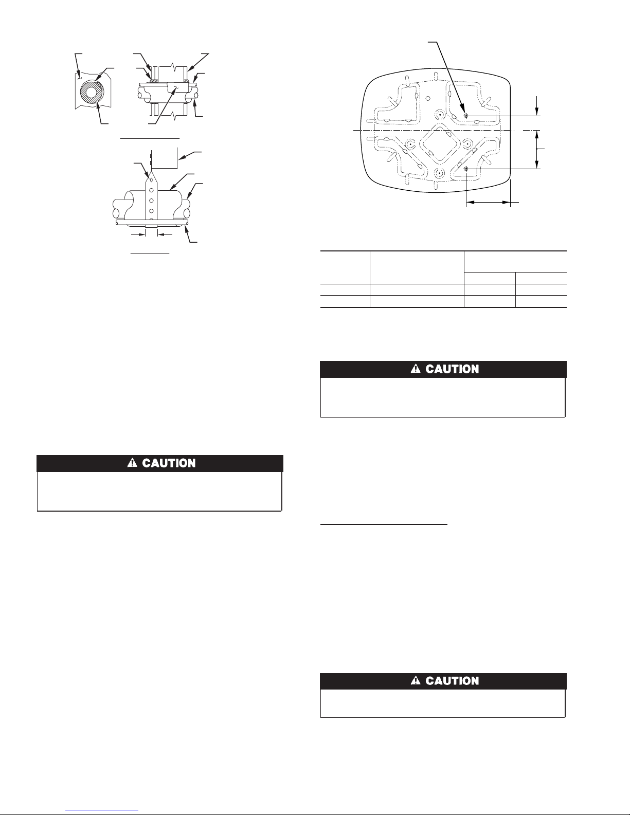
Avoid contact between tubing and structureNOTE:
OUTDOOR WALL INDOOR WALL
CAULK
LIQUID TUBE
3
/8-IN. DIA TIEDOWN
KNOCKOUTS IN BASEPAN
(2) PLACES
INSULATION
THROUGH THE WALL
HANGER STRAP
(AROUND VAPOR
TUBE ONLY)
1″ MIN.
SUSPENSION
VAPOR TUBE
JOIST
INSULATION
VAPOR TUBE
LIQUID TUBE
Fig. 2—Connecting Tubing Installation
INSPECT EQUIPMENT
File claim with shipping company prior to installation if shipment
is damaged or incomplete.
Step 2—Install on a Solid, Level Mounting Pad
If conditions or local codes require the unit be attached to pad, tie
down bolts should be used and fastened through knockouts
provided in unit base pan. Refer to unit mounting pattern in Fig. 3
to determine base pan size and knockout hole location.
On rooftop applications, mount on level platform or frame. Place
unit above a load bearing wall and isolate unit and tubing set from
structure. Arrange supporting members to adequately support unit
and minimize transmission of vibration to building. Consult local
codes governing rooftop applications.
Do not allow POE lubricant to come into contact with roofing
material. POE may deteriorate certain types of synthetic
roofing.
NOTE: Unit must be level to within ±2° (±3/8 in./ft).
Step 3—Clearance Requirements
When installing, allow sufficient space for airflow clearance,
wiring, refrigerant piping, and service. Allow 30-in. clearance to
service end of unitand 48 in. above unit. For proper airflow, a 6-in.
clearance on 1 side of unit and 12 in. on all remaining sides must
be maintained. Maintain a distance of 24 in. between units.
Position so water, snow, or ice from roof or eaves cannot fall
directly on unit.
Step 4—Operating Ambient
The minimum outdoor operating ambient in cooling mode is 55°F,
and the maximum outdoor operating ambient in cooling mode is
125°F.
→
Step 5—Install TXV
Puron® fan coils and furnace coils come factory equipped with a
bi-flow, hard shut off TXV specifically designed for Puron®
two-speed units. No TXV changeout is required. An existing R-22
TXV must be replaced with a factory approved TXV specifically designed for Puron® two-speed units.
NOTE: FK4, FC4, and 40FK fan coils are equipped with an R-22
TXV. If an FK4, FC4, or 40FK fan coil is used with a Puron® air
A01383
C
VIEW FROM TOP
Dimensions (In.)
UNIT SIZE
024 19 X 24 2-13/16 6-15/16
036-060 26 X 32 4 9-3/4
MINIMUM MOUNTING
PAD DIMENSIONS
TIEDOWN KNOCKOUT
LOCATIONS
AB
Fig. 3—Mounting Unit to Pad
conditioner, the R-22 TXV must be replaced with a factoryapproved Puron® TXV.
If indoor unit is equipped with piston, remove indoor coil
→
piston and replace with balance port hard shutoff TXV
metering device.
IMPORTANT: The 38TDB037 unit includes a factory supplied
→
TXV kit. All other sizes do not include factory supplied TXV kit.
TXV INSTALLATION
IMPORTANT: The TXV should be mounted as close to the
indoor coil as possible and in a vertical, upright position. Avoid
mounting the inlet tube vertically down. A factory supplied or
approved filter drier must be installed in the liquid line.
Installing TXV in Place of Piston
→
1. Remove any existing refrigerant and ensure coil has not been
exposed to atmospheric pressure for more than 15 minutes.
2. Remove indoor coil inlet tube at piston body inlet. Use
back-up wrench to prevent damage.
3. Remove piston retainer, begin careful not to damage scaling
surface of O-ring.
4. Remove and discard factory-installed piston. (Replace retainer
if O-ring is damaged.)
5. Reinstall piston retainer in piston body.
6. Replace indoor coil inlet tube. Use back-up wrench to prevent
damage.
To prevent damage to the unit, use a brazing shield and wrap
TXV with wet cloth.
7. Sweat swivel adapter (see Fig. 5D) to inlet of indoor coil and
attach to TXV (see Fig. 5A) outlet. Use backup wrench to
avoid damage to tubing or valve. Sweat Inlet of TXV, marked
“IN” to liquid line. Avoid excessive heat which could damage
valve
2
A
L
B
3
8
/16″
A97548
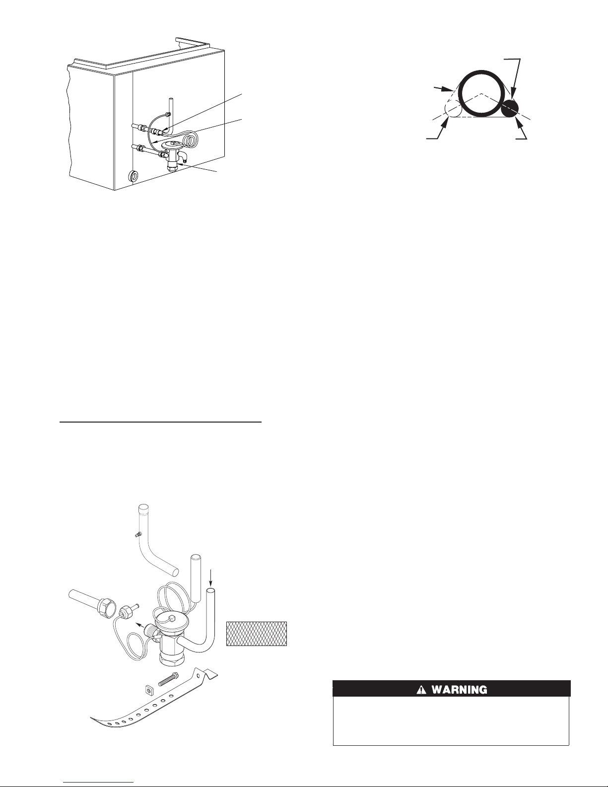
SENSING BULB
COIL
SENSING
BULB
EQUALIZER
TUBE
THERMOSTATIC
EXPANSION
VALVE
→
Fig. 4—TXV Installed
8. Install vapor elbow (see Fig. 5B) with equalizer adapter to
suction tube of line set and suction connection to indoor coil.
Adapter has a 1/4-in. male connector or attaching equalizer
tube.
9. Connect equalizer tube of TXV to 1/4-in. equalizer fitting on
vapor line adapter.
10. Attach TXV bulb to horizontal section of suction line using
bulb straps provided. (See Fig. 5C.) Insulate bulb with
factory-supplied insulation tape. (See Fig. 5E.) See Fig. 6 for
correct positioning of sensing bulb.
11. Proceed with remainder of unit installation.
→
FAN COIL
To obtain efficiency rating for 38TDB037 with FV4ANB006
fancoil TXV must be replaced with factory supplied TXV.
Replacing R-22 TXV or Non-Balance Port Puron TXV
→
1. Remove any existing refrigerant and ensure coil has not been
exposed to atmospheric pressure for more than 15 minutes.
2. Remove coil access panel and fitting panel from front of
cabinet.
3. Remove and save TXV support clamp using the 5/16-in. nut
driver. Save the clamp.
B
INLET
D
A
COIL
E
BULB
INSULATION
TAPE
C
A91277
STRAP
8 O'CLOCK
4 O'CLOCK
Fig. 6—Positioning of Sensing Bulb
4. Remove TXV using a backup wrench on flare connections to
prevent damage to tubing.
5. Using wire cutters, cut equalizer tube off flush with vapor tube
inside cabinet.
6. Remove bulb from vapor tube inside cabinet.
7. Braze equalizer stub-tube closed. Use protective barrier as
necessary to prevent damage to drain pan.
IMPORTANT: Route the equalizer tube of the approved Puron®
→
TXV through suction line connection opening in fitting door prior
to replacing fitting panel around tubing.
8. Install TXV (Fig. 5A) with 3/8-in. copper tubing through
small hole in service panel. Use wrench and backup wrench,
to avoid damage to tubing valve.
9. Reinstall TXV support clamp (removed in item 3).
10. Attach TXV bulb to vapor tube inside cabinet, in same
location as original was when removed, using supplied bulb
straps. (See Fig. 5C.) See Fig. 6 for correct positioning of
sensing bulb. Insulate bulb with factory-supplied insulation
tape. (See Fig. 5E.)
11. Route equalizer tube through suction connection opening
(large hole) in fitting panel and install fitting panel in place.
12. Sweat inlet of TXV, marked “IN” to liquid line. Avoid
excessive heat which could damage valve.
13. Install vapor elbow (see Fig. 5B) with equalizer adapter to
vapor line of line set and vapor connection to indoor coil.
Adapter has a 1/4-in. male connector for attaching equalizer
tube. (See Fig. 5B.)
14. Connect equalizer tube of TXV by 1/4-in. equalizer fitting, on
vapor line adapter. Use backup wrench to prevent damage to
equalizer fitting.
15. Proceed with the remainder of unit installation.
LONG-LINE APPLICATIONS
For refrigerant piping arrangements with equivalent lengths
greater than 50 ft or when elevation difference between indoor
and/or outdoor unit is more than 20 ft, follow all requirements of
the Long-Line Guideline section in the Application Guideline and
Service Manual—Air Conditioners and Heat Pumps Using Puron® Refrigerant.
Step 6—Make Piping Connections
A00399
Fig. 5—TXV Kit Contents
A01418
Relieve pressure and recover all refrigerant before system
repair or final unit disposal to avoid personal injury or death.
Use all service ports and open all flow-control devices,
including solenoid valves.
3
Do not leave system open to atmosphere any longer than
minimum required for installation. POE oil in compressor is
extremely susceptible to moisture absorption. Always keep
ends of tubing sealed during installation.
If ANY refrigerant tubing is buried, provide 6–in. vertical rise
at service valve. Refrigerant tubing lengths up to 36 in. may
be buried without further special consideration. Do not bury
lines for lengths over 36 in.
To prevent damage to unit or service valves, observe the
following:
• Use a brazing shield.
• Wrap service valves with wet cloth or use a heat sink
material.
Outdoor units may be connected to indoor section using accessory
tubing package or field-supplied refrigerant grade tubing of correct
size and condition. Tubing diameters listed in Table 1 are adequate
for equivalent lengths up to 50 ft. For tubing requirements beyond
50 ft, substantial capacity and performance losses will occur.
Follow the recommendations in the Application Guideline and
Service Manual—Air Conditioners and Heat Pumps Using Puron® Refrigerant to minimize losses.
Refer to Table 1 for field tubing diameters. Refer to Table 2 for
accessory requirements.
Do not bury lines over 36 in. long.
If refrigerant tubes or indoor coil are exposed to atmosphere, they
must be evacuated to 500 microns to eliminate contamination and
moisture in the system.
Table 1—Refrigerant Connections and
Recommended Liquid and Vapor Tube
Diameters (In.)
UNIT
SIZE
024 3/8 3/8 5/8 5/8 5/8 3/4
036 3/8 3/8 3/4 3/4 3/4 7/8
037, 048 3/8 3/8 7/8 7/8 7/8 7/8
060 3/8 3/8 7/8 1-1/8 7/8 1-1/8
Notes:
1. Tube diameters are for lengths up to 50 equivalent ft.
2. Do not apply capillary tube indoor coils to these units.
OUTDOOR UNIT CONNECTED TO FACTORY-APPROVED
INDOOR UNIT
Outdoor unit contains correct system refrigerant charge for operation with indoor unit of same size when connected by 15 ft of
field-supplied or factory-accessory tubing. Check refrigerant
charge for maximum efficiency
Installation of filter drier in liquid line is required.
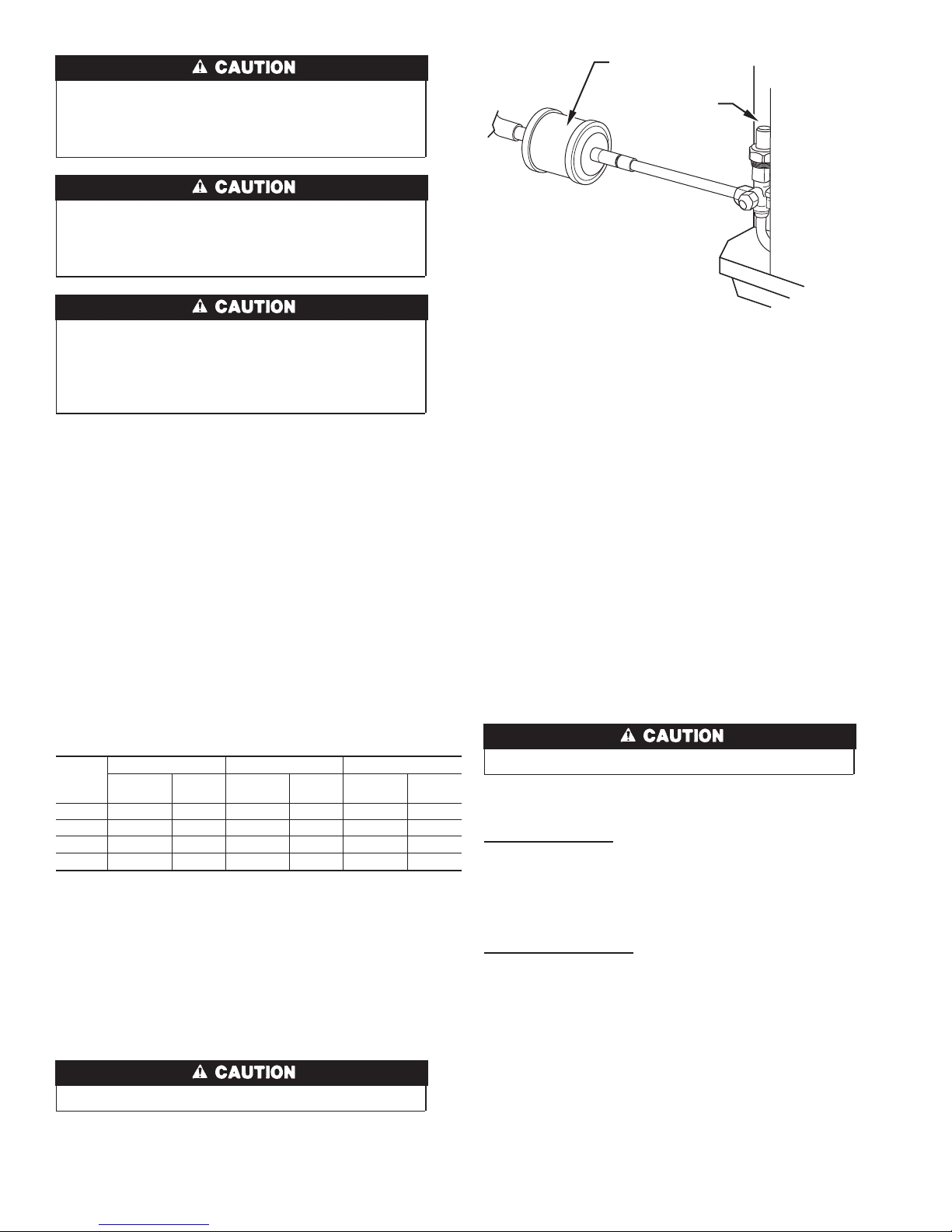
INSTALL LIQUID-LINE FILTER DRIER
Installation of filter drier in liquid line is required. Refer to Fig. 7
and install filter drier as follows:
LIQUID VAPOR VAPOR (LONG-LINE)
Connection
Diameter
Tube
Diameter
Connection
Diameter
Tube
Diameter
Connection
Diameter
Diameter
Tube
LIQUID-LINE
FILTER-DRIER
LIQUID
SERVICE
VALVE
A01215
Fig. 7—Filter Drier with Sweat Adapter Tube and
Liquid Tube
1. Braze 5–in. connector tube to liquid line service valve. Wrap
filter drier with damp cloth.
2. Braze filter drier between connector tube and liquid tube to
indoor coil. Flow arrow must point toward indoor coil.
REFRIGERANT TUBING
Connect vapor tube to fitting on outdoor unit vapor service valves.
Connect liquid tube to filter drier. (See Fig. 7and Table 1.)
SWEAT CONNECTION
Service valves are closed from factory and ready for brazing. After
wrapping service valve and filter drier with a wet cloth, braze
sweat connections using industry accepted methods and materials.
Do not use soft solder (materials which melt below 800°F).
Consult local code requirements. Refrigerant tubing and indoor
coil are now ready for leak testing. This check should include all
field and factory joints.
LEAK CHECKING
Leak test all joints in indoor, outdoor, and refrigerant tubing.
EVACUATE REFRIGERANT TUBING AND INDOOR COIL
Never use the system compressor as a vacuum pump.
Refrigerant tubes and indoor coil should be evacuated to 500
microns. Always break a vacuum with dry nitrogen.
Deep Vacuum Method
The deep vacuum method requires a vacuum pump capable of
pulling a minimum vacuum of 500 microns and a vacuum gage or
thermistor capable of accurately measuring this vacuum depth. The
deep vacuum method is the most positive way of assuring a system
is free of air and liquid water. (See Fig. 8.)
Triple Evacuation Method
The triple evacuation method should only be used when vacuum
pump is capable of pumping down to 28 in. of mercury and system
does not contain any liquid water. Refer to Fig. 9 and proceed as
follows:
1. Pump system down to 28 in. of mercury and allow pump to
continue operating for an additional 15 minutes.
2. Close service valves and shut off vacuum pump.
3. Connect a nitrogen cylinder and regulator to system and open
until system pressure is 2 psig.
4. Close service valve and allow system to stand for 1 hr. During
this time, dry nitrogen will be able to diffuse throughout the
system, absorbing moisture.
4
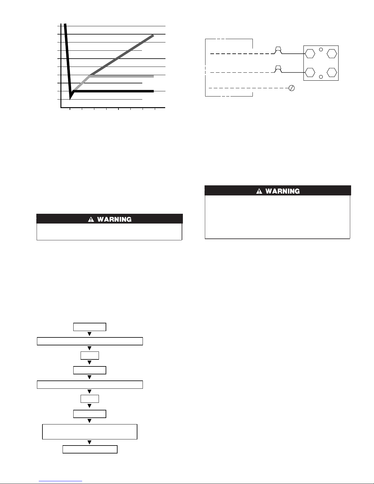
5000
4500
4000
3500
LEAK IN
SYSTEM
3000
2500
2000
MICRONS
1500
1000
500
01234567
MINUTES
VACUUM TIGHT
TOO WET
TIGHT
DRY SYSTEM
A95424
A95424
Fig. 8—Deep Vacuum Graph
5. Repeat this procedure as indicated in Fig. 9. System will then
contain minimal amounts of contaminants and water vapor.
FINAL TUBING CHECK
IMPORTANT: Check to be certain factory tubing on both indoor
and outdoor unit has not shifted during shipment. Ensure tubes are
not rubbing against each other or any sheet metal. Pay close
attention to feeder tubes, making sure wire ties on feeder tubes are
secure and tight.
Step 7—Make Electrical Connections
To avoid personal injury or death, do not supply power to unit
with compressor terminal box cover removed.
Be sure field wiring complies with local and national fire, safety,
and electrical codes, and voltage to system is within limits shown
on unit rating plate. Contact local power company for correction of
improper voltage. See unit rating plate for recommended circuit
protection device.
NOTE: Operation of unit on improper line voltage constitutes
abuse and could affect unit reliability. See unit rating plate. Do not
install unit in system where voltage may fluctuate above or below
permissible limits.
NOTE: Use copper wire only between disconnect switch and
unit.
EVACUATE
BREAK VACUUM WITH DRY NITROGEN
WAIT
EVACUATE
BREAK VACUUM WITH DRY NITROGEN
WAIT
EVACUATE
CHECK FOR TIGHT, DRY SYSTEM
(IF IT HOLDS DEEP VACUUM)
CHARGE SYSTEM
Fig. 9—Triple Evacuation Method
A95425
DISCONNECT
PER N. E. C. AND/ OR
LOCAL CODES
CONTACTOR
FIELD POWER
WIRING
FIELD GROUND
WIRING
GROUND
LUG
A91306
Fig. 10—Line Power Connections
NOTE: Install branch circuit disconnect of adequate size per
NEC to handle unit starting current. Locate disconnect within sight
from and readily accessible from unit, per Section 440-14 of NEC.
ROUTE GROUND AND POWER WIRES
Remove access panel to gain access to unit wiring. Extend wires
from disconnect through power wiring hole provided and into unit
control box. Size wires per NEC but not smaller than minimum
wire size shown in Product Data Digest.
The unit cabinet must have as uninterrupted or unbroken
ground to minimize personal injury if an electrical fault
should occur. The ground may consist of electrical wire or
metal conduit when installed in accordance with existing
electrical codes. Failure to follow this warning can result in an
electric shock, fire, or death.
CONNECT GROUND AND POWER WIRES
Connect ground wire to ground connection in control box for
safety. Connect power wiring to leads provided as shown in Fig.
10.
CONNECT CONTROL WIRING
Route 24v control wires through control wiring grommet and
connect to leads provided in control box. (See Fig. 11.)
Use No. 18 AWG color-coded, insulated (35°C minimum) wire. If
thermostat is located more than 100 ft from unit, as measured
along the control voltage wires, use No. 16 AWG color-coded wire
to avoid excessive voltage drop.
All wiring must be NEC Class 1 and must be separated from
incoming power leads.
The outdoor unit requires a minimum of 27va, 24vac control
power.
IMPORTANT: Check factory wiring and wire connections to
ensure terminations are secured properly. Check wire routing to
ensure wires are not in contact with tubing, sheet metal, etc.
Step 8—Install Electrical Accessories
GENERAL
Refer to the individual instructions packaged with kits or acces-
sories when installing.
Available electrical accessories include latent capacity control. See
Fig. 11 for typical accessory wiring diagrams.
LATENT CAPACITY CONTROL (LCC)
The purpose of an LCC is to provide a dehumidification mode to
assure a 75 percent or less system sensible heat ratio. If indoor unit
installed contains an ECM blower (such as an FK4C, FV4A, or
40FK fan coil or a 58CVA or 58MVP gas furnace), no LCC is
5
 Loading...