

Carrier TC-PBO01-BLK Installation Manual
TC-PBO01-BLK
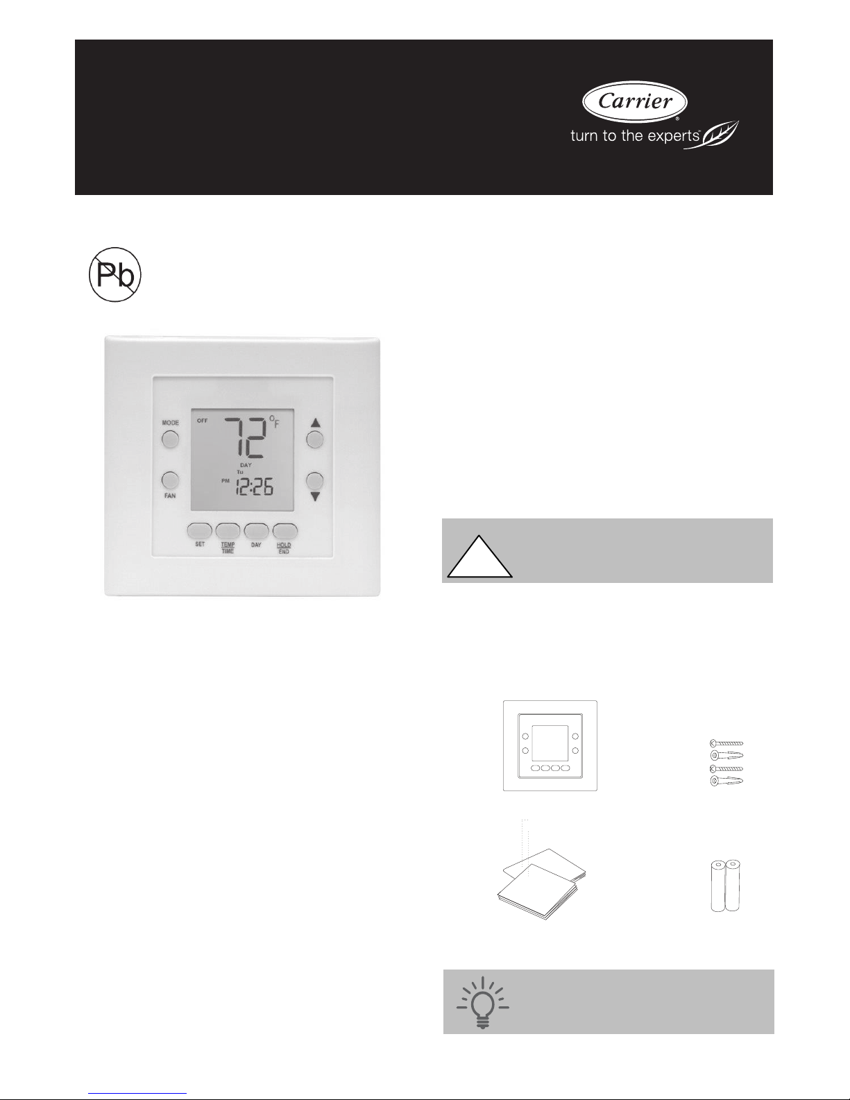
Carrier Programmable Thermostat
Air Conditioner and Heat Pump Applications
Installation Guide
Designed and Assembled
in the USA.
A150217
INTRODUCTION
Welcome and from all of us at Carrier®, thank you for purchasing
your new Carrier programmable thermostat. This thermostat is
designed to be simple to install but it’s best to review all of the
instructions in this manual before you start to help ensure there are
no surprises during installation.
If any questions arise during your installation, we’re here to help:
S Visit www.carrier.com/homecomfort for how- to videos and
answers to frequently asked questions.
S Technical support is also available by phone or email at:
COMPATIBLE HEATING AND COOLING
SYSTEMS
This thermostat works with many centralized residential heating
and cooling systems.
S Conventional Heating and Cooling (AC): one stage of heating
and one stage of cooling
S Heat Pump (HP): two stages of heating and one stage of cooling
S Heat pumps work to provide cooling in the summer but
in the winter, they do it in reverse, drawing their heat
energy from the outside air.
S Systems with a Common (C) wire
S Recommended to whenever possible
S Systems without a Common (C) wire
S Two alkaline AA batteries are are required.
This thermostat is not compatible with Duel Fuel or
Geothermal Systems or with Rh/Rc systems. Review
all documentation to ensure that you have selected the
!
appropriate model thermostat for your system.
ITEMS INCLUDED IN THE BOX
A. The Carrier®Programmable Thermostat
B. Mounting screws and drywall plugs
C. Installation Guide and Owner’s Manual
D. Batteries
A. B.
S 1.800.CARRIER or 1.800.227.7437
S contact.carrier@carrier.utc.com
S The thermostat is also supported by the world’s greatest network
of professional contractors. Find an Expert Carrier Contractor at
www.carrier.com/dealers.
Let’s get started!
Installation Guide
Owner’s Manual
C. D.
Tip: Write down your thermostat serial number
and save it for future reference. It is located on
the thermostat circuit board next to the model
number TB.
A150215

ITEMS YOU’LL NEED FOR
INSTALLATION
A. Pencil
B. Phillips screwdriver
C. Small flathead screwdriver
D. Drill with a 3/16” drill bit
or
A150046
Warning! Electrical operation hazard. Failure
!
to follow this warning could result in injury,
death, or equipment damage.
A. C.
B.
Tip: Review all the instructions before you
start to help ensure that there are no surprises
during installation
D.
A150218
Step 1 — REMOVE THE COVER FROM YOUR
OLD THERMOSTAT
1. Most covers snap off easily but some are attached by
screws. Remove the cover of your thermostat.
2. Note if either of the following apply to your old thermostat:
a. If you do not have a wire connected to C, two alkaline
AA batteries required.
b. If you find that you have additional wires labeled any-
thing other than Y, C, R, G, W, O/B – STOP and review
to see if this model thermostat is compatible with your
system
Y C R G W O/B
A150240
3. Reattach the cover of your old thermostat. You’ll use Step 2
to confirm the power is disconnected.
Warning! If your old thermostat is labeled
!
110V or 120V, or is connected by thick wires
and wire nuts, it is a high voltage system and is
not compatible
Step 3 — REMOVE YOUR OLD THERMOSTAT
1. Remove the cover of your old thermostat.
2. Using your old thermostat as a guide, record wire color and
corresponding letter where it is connected on the thermostat
terminal block. Don’t worry about any non- connected
wires .
Wire Color
Green G
Tip: Take a photo of your old thermostat wiring
with your smartphone for reference later.
3. Disconnect each wire. Most thermostats’ wires are connected using screws; simply loosen each screw with a small
screwdriver. Be careful not to let any wires fall back into the
wall.
4. Discard any jumper wires or brackets between Rh, Rc, or R.
Connected to Terminal
Letter
Step 2 — POWER OFF YOUR HEATING AND
COOLING SYSTEM
1. Turn off the power to your heating and cooling system.
S You can do this either at your circuit breaker box or a
switch at your indoor furnace or fan coil.
S Most systems have one switch but some systems have
two switches.
2. Make sure your system is without power by using your old
thermostat to adjust the temperature. Your system should
not turn on.
5. Remove your old thermostat base by unscrewing it from the
wall.
Step 4 — INSTALL YOUR CARRIER
®
THERMOSTAT
1. Separate front display and mounting back plate of thermostat.
2
A150219

2. Gently pull the wires through the hole in the back plate.
3. Center the wires in the back plate.
4. Mark the mounting holes on the wall with a pencil.
5. Drill mounting holes on the pencil marks with a 3/16” drill
bit.
6. Insert the plastic drywall anchors into the wall. Use the
screws provided to secure the back plate to the wall.
Step 5 — CONNECTING THE WIRES
1. Using the table you created on Page 2, use a small
screwdriver to loosen the screws then insert each wire into
its matching connector block hole
a. Insert only one wire in each connector.
Y C R G W O/B
b. Only connect wires that were connected to your old
thermostat.
c. If you need additional help with the wiring, refer to the
wiring diagrams beginning on Page 5.
2. After inserting a wire, tighten screw using a small
screwdriver.
O/B
A150241
A150235
A150240
a. If you connected a Common (C) wire, put J2 in the
“24VAC” position.
b. If you did not connect a Common (C) wire, leave J2 in
the default ”BATT” position.
C48
R6
Q9
R107
R47
BATT
J2
R48
C23
24VAC
D10
SST-B
D9
With Common Wire Connected
C48
R6
Q9
R107
BATT
J2
R48
C23
24VAC
D10
SST-B
NO Common Wire Connected
D9
Step 6 — CONNECTING THE DISPLAY
1. With the Carrier®logo positioned at the top, set the thermostat display into the 2 notches on the bottom of the mounting back plate.
2. Rotate the display forward and gently snap into place, making sure terminal block connector aligns and display is secure.
3. Remove the faceplate and insert batteries provided
a. Use your thumb and forefinger to grasp and the face-
plate away from the thermostat to expose the battery
terminals.
b. Insert batteries being careful to orient batteries in the
direction indicated by the embossed symbols on the
plastic
A150242
3. When all the wires are connected, gently push any excess
wire back into the wall.
4. Locate jumper marked J2 on the thermostat display’s circuit
board.
A150222
A150228
4. Replace faceplate.
5. Now you can turn the power back on to your heating and
cooling system. Return to your circuit breaker or on/off
switch and restore the power to your system.
3

6. The thermostat will automatically power on.
A150229
Step 7 — SET THERMOSTAT
CONFIGURATION
When power is first applied, AC will appear for 5 seconds to
indicate that the thermostat setup as an air conditioner (AC), the
most common application. You may need to make an adjustment to
this setting depending on the system you’ve connected. See
explanation under Option 01- Equipment Type below.
To adjust the default configuration, you will need to enter
Configuration Mode. A description of each configurable option is
listed below.
To Enter The Configuration Mode:
1. Press and hold the FAN key for about 10 seconds until the
display changes so that only two pairs of digits are showing.
A150230
2. The configuration number, now 01, will appear in the setpoint/temperature location and the configuration setting will
appear in the clock location.
3. The configuration number (left pair) will be flashing which
A150231
4. To cause the opposite pair to flash (to be adjustable), press
the MODE key.
A150232
5. Successive presses of the MODE key alternate between the
configuration number (left) and the configuration setting
(right).
6. To exit the configuration mode, press the HOLD/END key.
A150233
7. If no key is pressed for 3 minutes, the configuration mode
will automatically exit, returning the thermostat to normal
operation.
Option 01 - Equipment type
You may need to make an adjustment to this setting depending on
the system you’ve connected. If you’re unsure about your system
type, refer to wiring diagrams beginning on page 5.
Options: Air Conditioner (AC), Heat Pump (HP), PH, or PC
Description:
1. AC or PC controls 1 speed air conditioner with one stage of
heat.
2. HP or PH controls 1 speed heat pump with 1 stage of auxiliary heat.
3. PH or PC selects PTAC units (Packaged T erminal Air Conditioners) which are used in motel rooms and other rented
spaces. When this option is selected, the display shows only
the setpoint, not the room temperature. Also, the compressor timeguard is disabled, allowing the compressor to turn
on immediately when a demand is established.
Option 03 - Fahrenheit/Centigrade
Default: Fahrenheit (F)
Selections: Fahrenheit (F), Centigrade (C)
Description: This selection operates the thermostat in either
Fahrenheit or Centigrade.
Option 04 - G (fan) ON with W (Heat) Selection
Default: G not energized with W (OF)
Options: G not energized with W (OF), G energized with W (ON)
Description: This selection determines whether the fan (G) is to be
ON or OFF when W (furnace or strip heat) is ON. Furnaces and
fan coils which manage their own blowers do not require a separate
G signal. Some auxiliary heaters require a separate G signal to
operate the blower when W is applied.
Option 10 - Reversing valve
Default: Reversing valve energized in cooling (C)
Options: Reversing valve energized in cooling (C), Reversing
valve energized in heating (H)
Description: Applies only when configured for Heat Pump
applications. Most systems use the orange (O) wire and are
energized in cooling.
S Select Energized in Cooling (C) if you connected an (O) wire in
the O/B terminal to activate the reversing valve output when
there is a call for cooling.
S Select Energized in Heating (H) if you connected a (B) wire in
the O/B terminal to activate the reversing valve output when
there is a call for heating.
S If you are unsure, consult your heating and cooling system
equipment installation instructions or contact Carrier customer
support.
Option 13 - Room Air Temperature Offset
Default: 0°F
Options: +/- 5°For+/- 3°C.
Description: The number of degrees to be added to the displayed
temperature to calibrate the measured room temperature. The
selected number is the number of degrees, plus or minus, which
will be added to actual temperature. This option is in °Fevenif
Option03issetfor°C.
Option 15 - Auto Changeover
Default: Off (OF)
Options: On (ON), Off (OF)
Description: This feature allows the thermostat to automatically
change between heating and cooling mode when a demand has
been present in the opposite mode for a period of 20 minutes.
Manually changing either the cooling or the heating setpoint will
allow an auto changeover to occur without the 20 minute time
constraint. The heat setpoint and cool setpoint are separated by a
minimum of 2°F.
Option 21 - Keypad Lockout
Default: Off (OF)
Options: On (ON), Off (OF)
Description: With ON selected the keypad will be locked and can
be unlocked by simultaneously pressing the UP and DOWN keys
4
 Loading...