

Carrier 53KDMT24N-718, 53KDMT12N-718, 53KDMT36N-718, T53KDHT42N-518, T53KDHT48N-518 Installation Manual
...
Rev. (0) - 2014
Rev. (0) - 2016
Enviromental
Management System
ISO 14001 : 2004
Certicate No : 12 104 30334 TMS
Safety
Management System
BS OHSAS 18001 : 2007
Certicate No : 12 116 30334 TMS
03504574
INSTALLATION MANUAL
Miraco
Miraco
MISR REFRIGERATION & AIR CONDITIONING MFG. CO.
220-240V ~ 50Hz 1Ph
380-420V ~ 50Hz 3Ph
Carrier is committed for continuous improvement of Carrier products according to national and international standards
to ensure the highest quality and reliability standards, and to meet market regulations and requirements.
All specications subject to change without prior notice according to Carrier policy of continuous development.
Ceiling Concealed Ducted Split Systems
+igK (I¿ciency *Ueen
Cool Only
53KDMT12N-718
53KDMT18N-718
53KDMT24N-718
53KDMT30N-718
53KDMT36N-718T
53KDHT42N-518T
53KDHT48N-518T
53KDHT60N-518T
53KDHT72N-518T
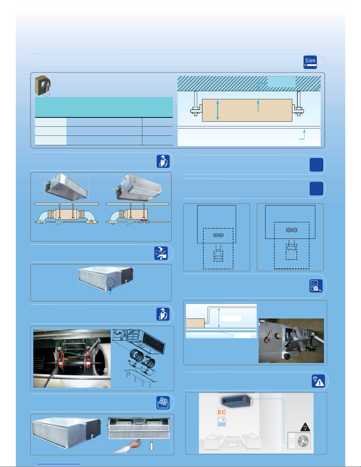
Features of Ducted Split Systems - Medium Static Pressure
Sizes 12K - 18K - 24K - 30K - 36K
Optional drain pump which can lift the
condensate water up to 750 mm upmost.
Optinal drain pump is factory installed
upon request.
750mm
ceiling
Easy and Flexible Installation
Due to compact dimensions, low height and low weight, the installation of ducted indoor unit - medium
static pressure on the ceiling is faster and extremely easy.
Min. 5mm
Drop - Ceiling
210 mm
270 mm
300 mm
Size
Dimensions (mm)
Net Weight
Kg
WHD
12K 920 210 635 23
18K - 24K 920 270 635 28
30K - 36K 1200 300 865 44.5
Low Height
Compact Dimensions & Light Weight
Smart Refrigerant leak detection by sensitive
sensor mounted on indoor coil for easy fast
service and maintenance.
Flexible two directions of air return :
Back air return ( factory standard )
Bottom air return ( can be done at eld ).
Bottom
Return
Air
Back
Return
Air
Pre-Punched Fresh intake air built in the indoor
unit from both sides to make air quality more
healthy and more comfortable.
Fresh air intake
Easy accessibility for motors and fans on indoor
unit for easy fast service and maintenance.
Motor
Bottom
Panel
Blower
housing
Easy removal of washable air lters for cleaning.
ON / OFF
Remote ON / OFF function provides more easy
central ON / OFF control of ducted split system.
Alarm
Remote system alarm function which required
for some applications such as computer rooms
for fast and easy service and maintenance.
Indoor Unit
Main Board
Alarm Output
ALARM
CN33
Indoor Unit
Main Board
CN23
ON / OFF
Remote Control
Ceiling
750 mm

Features of Ducted Split Systems - High Static Pressure
Sizes 42K - 48K - 60K - 72K
Return
Supply
INDOOR UNIT
Max. height of
air supply is 6.5 m
The longest distance
of air supply is 8m
Induct Some Fresh Air
Min. 5mm
Drop - Ceiling
380 mm
510 mm
Size
Dimensions (mm)
Net Weight
Kg
WHD
42K
1200 380 608 5648K
60K
72K 1470 510 795 83
Low Height
Compact Dimensions & Light Weight
High external static pressure design for
long distance of supply air duct.
160
Pa
750mm up most
Optional drain pump which can lift the
condensate water up to 750 mm upmost.
Optinal drain pump is factory installed
upon request.
1. Control box
2. Fan casing
3. Motor
4. Bottom panel
Easy accessibility for motors and fans on indoor
unit for easy fast service and maintenance.
1
2
3
4
Easy removal of washable aluminium air lters
for cleaning.
Standard Smart Wired Controller with complete
control functions built in the control system.
Smart Refrigerant leak detection by sensitive
sensor mounted on indoor coil for easy fast service
and maintenance.
Easy and Flexible Installation
Due to compact dimensions, low height and low weight, the installation of ducted indoor unit - High static
pressure on the ceiling is faster and extremely easy.
swing
swing
12345678
Day
Week
Auto Cool Dry
AB
Heat Fan OFF
Auto
SU MO TU WE TH FR SA
On
Off

TABLE OF CONTENTS
PAGE NO.
1.
General Notes To Installer 1
2.
Precautions Before Installation 2
3.
Ducted Split System Description 3
4.
Unit Models & Identification 7
5.
Operating Limits 7
6.
Dimensions And Weights of Ducted Indoor Units 8
7.
Dimensions And Weights of Outdoor Unit 11
8.
Selecting Installation Location of Indoor Unit 13
9.
Selecting Installation Location of Side Discharge Outdoor Unit 14
10.
Selecting Installation Location of Top Discharge Outdoor Unit 21
11.
Installation Location – Check List 23
12.
Installation Accessories 24
13.
Installation Chart 25
14.
Indoor Unit Installation 27
15.
Installation of Wired Room Controller 31
16.
Installation of Display and Receiver Panel 34
17.
Outdoor Unit Installation 37
18.
Connecting Refrigerant Piping Lines 39
19.
Installation of Fresh Air Duct For Ducted Indoor Unit – Medium Static Pressure
63
20.
Installation Drain Line of Indoor Unit 64
21.
Connecting Electrical Wiring 66
22.
Setting of Switches 74
23.
Finishing Installation 76
24.
Test Running 77
25.
After Installation Check List 78
26.
Self Diagnostic Function For Malfunctions Detection 80

1
1. GENERAL NOTES TO INSTALLER
Ducted split air conditioner has been carefully designed and manufactured under strict Quality
Control conditions.
Therefore you are completely responsible for proper installation completion and operation of the
air conditioner.
Carefully read the manual carefully before proceeding with the installation to ensure correct
installation. This manual describes installation instructions to help ensure trouble free operation
and extended life of the air conditioner.
Make sure all accessory parts are with the system before beginning installation.
You will need the following tools for installation:
1.
Standard screwdriver
10.
Flaring tool set
2.
Phillips head screw driver
11.
Pipe bender
3.
Electric drill, Hole core drill
12.
Hexagonal wrench ( 4mm )
4.
Measure tape
13.
Torque wrench
5.
Water level gauge
14.
Vacuum pump matched with Air conditioner R410A
6.
Pipe clamp
15.
Gas leak detector for refrigerant R410A
7.
Pipe cutter
16.
Gauge manifold R410A
8.
Spanner ( half union )
17.
Thermometer
9.
Reamer
18.
Electrical multimeter
Important
• During the system installation make first refrigerant piping connections and then electrical
connections.
• If the system is uninstalled first disconnect electrical cables and then refrigerant piping
connections.
After completion of installation, perform a run test and give the customer full
instructions on the correct operation of the air conditioner including:
• Turning the unit on and off.
• Removal and cleaning of the air filters.
• Functions of the wired control.
• Re-installation of air filters after cleaning
Leave the owner manual with the customer so that it can to be used during operation of the air
conditioner.
Leave the installation manual with the customer so that it can be used for any service and
maintenance operations.
Advise the customer to the tips of energy saving while operating the air conditioner as
mentioned in the owner’s manual.
Warning
Disconnect the mains power supply switch before servicing the system or handling any internal parts
of the system.

2
2. PRECAUTIONS BEFORE INSTALLATION
SAFETY PRECAUTIONS
x
Installation and maintenance of air conditioning equipment can be hazardous due to system
pressures, electrical components and rotating parts.
x The installation and maintenance of the air conditioner must be carried out by trained and
qualified technicians from Carrier or one of Carrier authorized dealers.
x After unpacking, Please check carefully for possible damage the indoor and outdoor units
of the air conditioner.
x
Before undertaking any work on the indoor and outdoor units of the air conditioner, make sure
to disconnect the power supply.
WARNING
x This installation manual describes the installation procedures of split room air conditioner
consisting of an outdoor unit and an indoor unit manufactured by Carrier.
x The installation of air conditioner must be according to applicable national installation
standards.
x
During installation, Proceed first with refrigerant connections between indoor and outdoor
units, and only then make the electrical connections.
Similarly, when disassembling, disconnect the electrical wiring first and only then open
refrigerant connections.
What is not covered in our warranty?
1- Failure due to wrong electrical connections between the electrical power supply and
circuit breaker of air conditioner leading to fire due to short-circuitin
g. As these electrical
connections are owner’s responsibility.
2- Failure due to Misuse, Abusing, overloading, negligence of air filters cleaning and
negligence of instructions included in the owner’s manual.
3- Failure due to Accident / Weather Natural catastrophe, accident due to bad weather
(Hail Storm, Sand Storm, lightning, Flooding, Acid Rain and Air Borne fallout, etc).
4- Failure due to damages during transport done through the owner.
5- Failure due to any modifications in the product done through the owner.
6- Failure due to Installation or Service and Maintenance or repair works
done through the owner.
7- Product normal sound ( refrigerant – moving parts – plastic parts )
8- Inconvenience or commercial loss is not covered.
The decision of Carrier in ascertaining the same will be final. Any such repairs will be carried
-
out at the expense of the owner ( purchaser ).
3
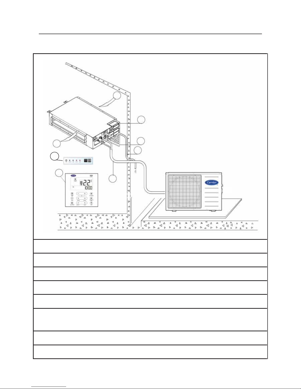
3. DUCTED SPLIT SYSTEM DESCRIPTION
3.1 Ducted Split System – Medium Static Pressure 12K – 18K – 24K – 30K
1: Supply Air From Indoor Unit
2: Return Air To Indoor Unit
3: Air Filter (s)
4: Electrical Box
5: Condensate Drain Hose
6: Inter-connecting refrigerant piping lines and electrical cables
between outdoor and indoor units.
7: Wired Room Controller ( Standard )
8: Display & Receiver Panel for optional wireless remote control
Ducted
Indoor Unit
Medium Static Pressure
Outdoor Unit
Side Discharge
1
2
3
4
5
6
7
8

4
DUCTED SPLIT SYSTEM DESCRIPTION
3.2 Ducted Split System – Medium Static Pressure 36K
1: Supply Air From Indoor Unit
2: Return Air To Indoor Unit
3: Air Filter (s)
4: Electrical Box
5: Condensate Drain Hose
6: Inter-connecting refrigerant piping lines and electrical cables
between outdoor and indoor units.
7: Wired Room Controller ( Standard )
8: Display & Receiver Panel for optional wireless remote control
1
2
3
4
5
6
7
Indoor Unit
Medium Static Pressure
Outdoor Unit
Top Discharge
8

5
DUCTED SPLIT SYSTEM DESCRIPTION
3.3 Ducted Split System – High Static Pressure 42K – 48K – 60K
1 : Supply Air To Indoor Unit
2 : Return Air From Indoor Unit
3 : Air filter (s)
4 : Electrical Box
5 : Condensate Drain Hose
6 : Inter-connecting refrigerant piping lines and electrical cables
between outdoor and indoor units.
7 : Wired Room Controller ( Standard )
8 : Display & Receiver Panel for optional wireless remote control
1
2
5
6
3
4
7
Ducted
Indoor Unit
High Static Pressure
Outdoor Unit
Top Discharge
8

6
DUCTED SPLIT SYSTEM DESCRIPTION
3.4 Ducted Split System – High Static Pressure 72K
1 : Air filter (s)
2 : Indoor Coil
3 : Return Air To Indoor Unit
4 : Supply Air From Indoor Unit
5 : Electrical Box
6 : Inter-connecting refrigerant piping lines and electrical cables
between outdoor and indoor units.
7 : Condensate Drain hose
8 : Wired control ( Standard )
9 : Display & Receiver Panel for optional wireless remote control
Top Discharge
Outdoor Unit
1
4
7
6
3
5
8
Indoor Unit
High Static Pressure
2
9

7
4. UNIT MODELS & IDENTIFICATION
Unit Models
System Model
Indoor Unit Model
Outdoor Unit Model
53KDMT12N-718
42KDMT12N-718
38KDMT12N-718
53KDMT18N-718
42KDMT18N-718
38KDMT18N-718
53KDMT24N-718
42KDMT24N-718
38KDMT24N-718
53KDMT30N-718
42KDMT30N-718
38KDMT30N-718
53KDMT36N-718T
42KDMT36N-718T
38KDMT36N-718T
53KDHT42N-518T
42KDHT42N-718T
38KDHT42N-518T
53KDHT48N-518T
42KDHT48N-718T
38KDHT48N-518T
53KDHT60N-518T
42KDHT60N-718T
38KDHT60N-518T
53KDHT72N-518T
42KDHT72N-718T
38KDHT72N-518T
Identification : 53 = Split System
42 = Indoor Unit
38 = Outdoor Unit
K = Cool Only
D = Ducted
M = Medium Static Pressure
H = High Static Pressure
T = Tropical High Ambient
18 = System Size
N = R410A Green Refrigerant
7 = Power Supply 220-240V/1Ph/50Hz
5 = Power Supply 380-420V/3Ph/50Hz
1 = Wired Room Controller
8 = Manufactured by Miraco – Carrier
T = Outdoor Unit – Top Discharge
5. OPERATING LIMITS *
COOLING
Difference
Dry Bulb
Temp. C°
Wet Bulb
Temp. C°
Indoor temperature
Maximum
Minimum
32
21
23
15
Outdoor temperature
Maximum
Minimum
52
21
-
-
MAIN POWER SUPPLY
System
Model
Nominal Power Supply
V / PH / HZ
Minimum
Voltage
Maximum
Voltage
53KDMT12N-718
220-240 / 1 / 50 198 254
53KDMT18N-718
53KDMT24N-718
53KDMT30N-718
53KDMT36N-718T
53KDHT42N-518T
380-415 / 3 / 50 342 462
53KDHT48N-518T
53KDHT60N-518T
53KDHT72N-518T
NOTE:
* When the ducted split systems is operated above or below these limits for a long time, system
diagnostics may detect a malfunction and the system will not operate properly.

8
6. DIMENSIONS AND WEIGHTS OF DUCTED INDOOR UNITS
6.1 Ducted Indoor Units - Medium Static Pressure Sizes 12K, 18K, 24K, 30K, 36K
- The refrigerant piping connections and control box are located on the right hand side
of the indoor unit when facing supply air side of the unit.
- The indoor unit should be installed for horizontal supply air flow.
- The indoor unit should be suspended horizontally using the factory provided holes located
at the topside flanges of the indoor unit.
Indoor Unit
Model
Weight
Outline dimesions
Supply air
opening size
Return air
opening size
Size of
Mounted lug
A B C D E F G H I J K L M
42KDMT 12
23
920
210
635
570
65
713
35
119
815
200
80
960
350
42KDMT 18 - 24
28
920
270
635
570
65
713
35
179
815
260
20
960
350
42KDMT 30 - 36
44.5
1200
300
865
800
80
968
40
204
1094
288
45
1240
500
Outline dimensions (mm)
Electrical Box
Electrical Box
Aluminum Mesh
Air Filter
Back return air opening size
Bottom return air opening position
Size of mounted lug
C
D
A
F
B
E
H
G
I
K
L
M
J
Kg
Supply air opening size
Aluminum Mesh
Air Filter

9
DIMENSIONS AND WEIGHTS OF DUCTED INDOOR UNITS
6.2 Ducted Indoor Units - High Static Pressure Sizes 42K, 48K, 60K
- The refrigerant piping connections and control box are located on the right hand side
of the indoor unit when facing supply air side of the unit.
- The indoor unit should be installed for horizontal supply air flow.
- The indoor unit should be suspended horizontally using the factory provided holes located
at the topside flanges of the indoor unit.
Weight
Model
Kg
42KDHT42N-718T
56
42KDHT48N-718T
56
42KDHT60N-718T
56
Dimensions ( mm )
Number
Name
Descript ion
1
Suction pipe connection
---
2
Liquid pipe connection
---
3
Drain pipe connection
OD Ø 25 ID Ø 20
4
Drain pipe connection
Using drain pump (optional)
5
Power supply connection
---
6
Supply air flange
---
7
Aluminium mesh air filter
10 mm thick
Kg
1200
Ø 5
2- Ø 3.2
1000 ( Supply air duct flange )
10
10
900
270
14
29
550
325
925
1145 ( Return air duct flange )
1236 ( Suspension position )
495 ( suspension position)
29
14
380
6
6
14 29130
1
2
3
4
5
170
14
29
7
Ø 5
2- Ø 3.2
10
10
1200
380
608
253
Supply air
duct flange
334
Return air
duct flange
Note
12 groups
all around

10
DIMENSIONS AND WEIGHTS OF DUCTED INDOOR UNITS
6.3 Ducted Indoor Unit - High Static Pressure Size 72K
- The refrigerant piping connections and electrical control box are located on the left hand side of
indoor unit when facing supply air flow of indoor unit.
- The indoor unit should be installed horizontally for horizontal discharge only.
Using the factory-provided holes located at the topside flanges of the indoor unit.
Weight
Model
Kg
42KDHT72N-718T
83
Dimensions ( mm )
Pipe side view
Kg
795
1470
510
510
398
112
75
66
238
45
24

11
7. DIMENSIONS AND WEIGHTS OF OUTDOOR UNIT
7.1 Side Discharge Outdoor Units Sizes 12K, 18K, 24K, 30K
Model
Unit Dimensions
(mm)
Weight
Width
Height
Depth
38KDMT12N-718
770
555
300
37
Mounting Dimensions
Model
Unit Dimensions
(mm)
Weight
Width
Height
Depth
38
KDMT18N-
718
845
700
320
48.5
Mounting Dimensions
Model
Unit Dimensions
(mm)
Weight
Width
Height
Depth
38KDMT24N-718
945
810
395
60
Mounting Dimensions
Model
Unit
Dimensions
(mm)
Weight
Width
Height
Depth
38KDMT30N-718
945
810
395
70.5
Mounting Dimensions
Kg
Kg
Kg
Kg
560
640
405
640
405
487
298

12
H
D
W
Top View
Down View
A
B
Front View
DIMENSIONS AND WEIGHTS OF OUTDOOR UNIT
7.2 Top Discharge Outdoor units Sizes 36K & 42K & 48K & 60K & 72K
Model
Mounting
Dimensions
(mm)
Unit
Dimensions
(mm)
Weight
A
B
W
H D
38KDMT 36N-
718T
754
753
710
843
710
84.5
38KDHT42N-
518T
80
38KDHT48N-
518T
80
38KDHT60N-
518T
785
784
740
843
740
102
38KDHT72N-
518T
Top Air Discharge
Air Inlets
Refrigerant & electrical
connections
Hole for
Control Wiring
1-11/32” (34.5mm)
Hole for
Power Wiring
7/8” (22.2mm)
Gas Line
C
onnection
Liquid Line
Connection
Kg
H

13
8. SELECTING INSTALLATION LOCATION OF INDOOR UNIT
8.1 CONSIDERATIONS OF SELECTING INSTALLATION LOCATION
For Ducted Indoor Unit - Medium Static Pressure
Select installation location which allows
minimum clearances for free air circulation
and easy accessibility for easy
service and
maintenance.
For Ducted Indoor Unit - High Static Pressure
Avoid installation location which can lead to
excessive length of refrigerant piping lines
between outdoor and indoor units
Avoid installation location which can lead to
excessive height difference between
outdoor and indoor units
Select Installation location which should be able to support indoor unit operating weight.
The ceiling should be horizontal
Select Installation location which should permit easy connection of refrigerant piping lines,
electrical cables and condensate drain line.
200 mm or more
600mmX600mm
checking orifice
300 mm or more
600mmX600mm
checking orifice
600 mm or more
500 mm or more
Maintenance room age

14
9. SELECTING INSTALLATION LOCATION OF SIDE DISCHARGE - OUTDOOR UNIT
9.1 INSTALLATION LOCATIONS
The side discharge outdoor unit can be installed in any outside location, on a wall,
on a roof or on a ground level.
9.2 CONSIDERATIONS FOR SELECTING INSTALLATION LOCATIONS
Avoid installation location which can lead
to excessive distance between outdoor
and indoor units to avoid alteration on
system cooling performance.
Avoid installation location which can lead
to excessive height difference between
outdoor and indoor units to avoid
alteration on system cooling performance.
Avoid installation location which can lead
to unnecessary turns and bends in the
refrigerant piping lines connecting
outdoor unit with indoor unit.
Avoid installation location where there are
obstacles near the air outlet or air inlet
that may affect air flow and performance
of the unit
Avoid multiple unit installation with units
facing each other and blowing discharged
air into each other.
15
SELECTING INSTALLATION LOCATION OF SIDE DISCHARGE - OUTDOOR UNIT
CONSIDERATIONS FOR SELECTING INSTALLATION LOCATION
Select installation location which is close to the indoor unit.
Select the installation location of outdoor unit which is able to support operating weigh
t
of outdoor unit, and not cause vibration.
Select the installation location of outdoor unit which is far away from the direct
sunlight.
Select the installation location of outdoor unit which is far away from heat sources,
steam or flammable gas.
Select the installation location of outdoor unit which is free of dust or any material,
which can cause clogging of condenser coil. When installing unit on the ground, select
a location not subjected to flooding.
Avoid installation location which is full of oil vapors which may result in malfunction.
Avoid installation location which is full of sulfuric gas which may result in malfunction.
Select installation location where the operation noise and discharged air are not
disruptive to your neighbors.
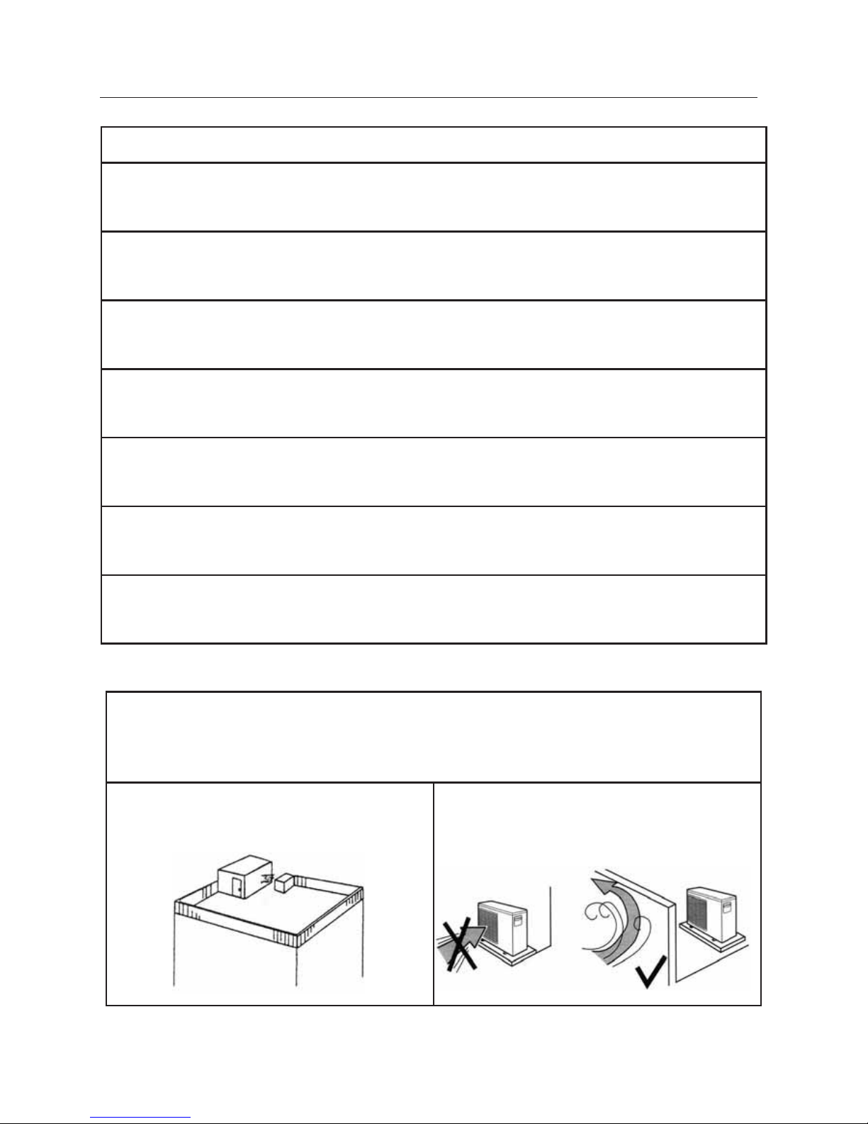
When the installation is made on the rooftop or other places subject to strong wind :
When the outdoor unit is to be installed on the rooftop or at the places where there are no other
buildings around. it is required to avoid the strong wind from blowing dir
ectly into the air outlet of the
outdoor unit so as to prevent the negative impacts on cooling performances due to insufficient airflow
of the outdoor unit heat exchanger and to prevent from faulty performances.
When there are walls in the vicinity, the air outlet
should face the wall and keep a space of 500mm
from the wall.
When the air outlet is affected by the strong wind,
the installation position should be changed so as
to make the air outlet at a straight angle from the
wind direction.

16
SELECTING INSTALLATION LOCATION OF SIDE DISCHARGE - OUTDOOR UNIT
9.3 Minimum Clearances When Selecting Installation Location for Single Outdoor Unit Installation
Minimum Clearances When Selecting Installation Location for Serial Installation
of More Than One Outdoor Unit
Select installation location which allows the minimum clearances shown in the figures for free
air circulation and easy accessibility for service and maintenance :
The front of outdoor unit ( air outlet )
should be away from any obstacle by 500 mm or more to ensure free air circulation.
The back of outdoor unit ( air inlet )
should be away from any obstacle by 160 mm or more. This distance is built in the design of wall support
to ensure free air circulation.
The left side of outdoor unit
should by away from any obstacle by 400 mm or more to ensure easy access to refrigerant and electrical
connections.
The right side of outdoor unit ( air inlet )
should be away from any obstacle by 250 mm or more to ensure free air circulation.
The top side of outdoor unit
should be away from any obstacle by 400 mm or more to ensure easy access to the electrical
components, motor and fan.

17
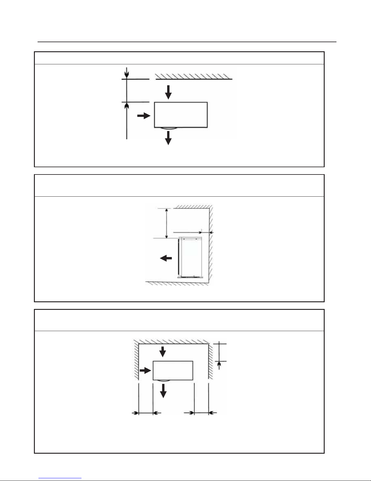
SELECTING INSTALLATION LOCATION OF SIDE DISCHARGE - OUTDOOR UNIT
Minimum Clearances When Selecting Installation Location for Single Outdoor Unit Installation
Obstacle at unit front ( air outlet )
No obstacle at back or top or right or left
Obstacle at unit front ( air outlet ) &
Obstacle at unit back ( air inlet )
Note: The height of Obstacle should be less than the height of outdoor unit
No obstacle at top or right or left
Obstacle at unit front ( air outlet ) &
Obstacle at unit top
No obstacle at back or right or left
100 cm
or more
16 cm
or more
50 cm
or more
Outdoor
Unit
Obstacle
Outdoor
Unit
Obstacle
Obstacle
100 cm
or more
100 cm
or more
Obstacle
Outdoor
Unit
18
SELECTING INSTALLATION LOCATION OF SIDE DISCHARGE - OUTDOOR UNIT
Minimum Clearances When Selecting Installation Location for Single Outdoor Unit Installation
Obstacle at unit back ( air inlet )
No obstacle at front or top or right or left
Obstacle at unit back ( air inlet ) &
Obstacle at unit top
No obstacle at front or right or left
Obstacle at unit back ( air inlet ) &
Obstacle at unit right and left sides
No obstacle at front or top
16 cm
or more
Outdoor
Unit
Obstacle
16 cm
or more
Obstacle
40 cm
or more
25 cm
or more
Obstacle
16 cm
or more
Outdoor
Uni
t
Obstacle
40 cm
or more
Outdoor
Unit

19
SELECTING INSTALLATION LOCATION OF SIDE DISCHARGE - OUTDOOR UNIT
Minimum Clearances When Selecting Installation Location for Serial Installation of More Than One Outdoor Unit
Obstacle at unit front ( air outlet )
No obstacle at back or top or right or left
Obstacle at unit front ( air outlet ) &
Obstacle at unit back ( air inlet )
Note: The height of obstacle should be less than the height of outdoor units
No obstruction at top or right or left
Obstacle at unit back ( air inlet )
No obstacle at front or top or right or left
100 cm
or more
16 cm
or more
40 cm
or more
100 cm
or more
Outdoor
Unit
Obstacle
Obstacle
Obstacle
16 cm
or more
Obstacle
Outdoor
Unit
Outdoor
Unit
Outdoor
Unit
Outdoor
Unit
Outdoor
Unit
Outdoor
Unit
Outdoor
Unit
Outdoor
Unit
40 cm
or more
Outdoor
Unit
Outdoor
Unit
Outdoor
Unit
40 cm
or more
40 cm
or more

20
SELECTING INSTALLATION LOCATION OF SIDE DISCHARGE - OUTDOOR UNIT
Minimum Clearances When Selecting Installation Location for Serial Installation of More Than One Outdoor Unit
Obstacle at unit back ( air inlet ) &
Obstacle at right and left sides
No obstacle at front or top
No obstacle at front or top
16 cm
or more
Obstacle
100 cm
or more
40 cm
or more
200 cm
or more
150 cm
or more
16 cm
or more
40 cm
or more
40 cm
or more
Obstacle
40 cm
or more
25 cm
or more
Obstacle
Obstacle
Obstacle
Outdoor
Unit
Outdoor
Unit
Outdoor
Unit

21
10. SELECTING INSTALLATION LOCATION OF TOP DISCHARGE - OUTDOOR UNIT
10.1 INSTALLATION LOCATIONS
The outdoor unit can be installed in any outside location on a ground level or on a roof.
10.2 CONSIDERATIONS FOR SELECTING INSTALLATION LOCATION
Select installation location which is close to the indoor unit.
Select installation location which is close to the electrical power supply.
Avoid installation location which can lead to excessive distance between outdoor and
indoor units to avoid alteration on system cooling performance.
Avoid installation location which can lead to excessive height difference between indoor
and outdoor units to avoid alteration on system cooling performance.
Avoid installation location which can lead to unnecessary turns and bends in the
refrigerant piping lines connecting outdoor unit with indoor unit.
Avoid installation location where there are obstacles near the air outlet or air inlet that
may affect air flow and system cooling performance.
Avoid multiple outdoor unit installation with units facing each other and blowing
discharged air into each other.
For multiple outdoor units installation, the outdoor units must be spaced a minimum of
50cm ( coil face to coil face ).
Select the installation location of outdoor unit which is able to support operating weight
of outdoor unit, and not cause vibration.
Select the installation location of outdoor unit wh
ich is far away from the direct sunlight.
Select the installation location of outdoor unit which is far away from heat sources,
steam or flammable gases.
Select the installation location of outdoor unit which is free of dust or any material,
which can cause clogging of outdoor coil. When installing unit on the ground, select a
location not subjected to flooding.
Avoid installation location which is full of oil vapors which may result in malfunction.
Avoid installation location which is full of sulfuric gas which may result in malfunction.
Select installation location where the operation noise and discharged air are not
disruptive to your neighbors.

22
SELECTING INSTALLATION LOCATION OF TOP DISCHARGE - OUTDOOR UNIT
CONSIDERATIONS FOR SELECTING INSTALLATION LOCATION
Select installation location which allows the minimum clearances shown in the figures
for free air circulation and easy accessibility for service and maintenance :
The top of outdoor unit ( air outlet )
should be away from any obstacle by 150 cm or more to ensure free air circulation.
The front, back, right and left of outdoor unit ( air inlet )
should be away from any obstacle by 30 cm or more to ensure free air circulation and easy access
to refrigerant and electrical connections.
Obstacles at outdoor unit top ( air outlet )
No obstacle at front or back or right or left
Obstacles at outdoor unit front & back & right and left sides ( air inlets )
No obstacle at top
Outdoor
Unit
Obstacle
30 cm
or more
30 cm
or more
30 cm
or more
30 cm
or more
Air
Inlet
Air
Inlet
Air
Outlet
150 cm
or more
Air
Inlet
Air
Inlet
Air
Inlet
Air
Inlet
Obstacle
Obstacle
Obstacle
Obstacle

23
11. INSTALLATION LOCATION CHECK LIST
(A) INDOOR UNIT
- The installation location is close to the outdoor unit
- The wall hole (required to pass refrigerant piping, electrical cables and drain line)
is on the unit right back
- The installation location permit the unit to deliver air to all of the space
to be air-conditioned
- The installation location avoid obstructions, which affect motion of supply and/or
return air to the unit
- The installation location permit free service space around the unit right, left, front
back and top
(B)
OUTDOOR UNIT
- The electrical power supply is close to the outdoor unit
- The installation location is close to the indoor unit
- The installation location is able to support operating weight of outdoor unit
- The installation location is far away from any sunlight
- The installation location is free of dust or any material,
which can cause clogging of outdoor coil
- The installation location allow sufficient space
for air circulation around the unit
- The installation location allow sufficient space
for service and maintenance around the unit
- The installation location is selected so that the operation
noise and discharge air do not disturb the neighbors
(C)
REFRIGERANT PIPING LINES BETWEEN INDOOR AND OUTDOOR UNITS
- The excessive length of refrigerant piping lines is avoided
- The excessive height between outdoor and indoor units is avoided
- The excessive number of turns and bends in the refrigerant piping lines is avoided
 Loading...