

Carrier Fa4anc048 Owner's Manual
FA4A
FB4A
Product
FC4B
®
Data
Direct Expansion
Fan Coil
Sizes 018 thru 070
Air Handling Technology At
Its Finest
Carrier’s FA4A, FB4A, and FC4B
direct expansion multipoise fan coils
are designed to cover a wide range
of air handling requirements. They
are compact and ready to fit where
needed — in the basement, crawlspace, attic, utility room, or closet.
All units come with solid-state
power board controls, 1-in. insulation
with an R value of 4.2, super-quiet
multispeed motors, and fully wettable
coils. Units can accommodate factoryor field-installed heaters from 3 to
30 kw.
The FA4A is the residential new
construction (RNC) model in the
line-up. It is available with or
without factory installed disconnects. It has an embossed
galvanized steel casing, 2-speed
motor in 018 through 036 sizes
and 3-speed motor in 042 through
060 sizes. The FA4A is equipped
with an AccuRater
The FB4A is the standard of
Carrier fan coils. It comes in a
prepainted galvanized steel casing
with foil-faced insulation and has a
3-speed motor in the full range of sizes
018 through 070. All units are
equipped with an AccuRater metering
device and are also shipped with a
cleanable, permanent framed filter.
The FC4B is the deluxe design in
the fan coil group. It incorporates all
the features found in the FB4A. In
addition, it has a hard shut-off
thermostatic expansion valve (TXV)
metering device with internal check
valves for reverse-flow bypass
capability. The FC4B is available in
sizes 024 through 070.
®
metering device.
Copyright 1997 Carrier Corporation Form FA4A-6PD

Standard features
•
Grooved copper tubing
•
Lanced sine-wave aluminum fin
•
Fully wettable coils
•
High-impact thermoplastic condensate pan
•
Primary and secondary drain connection with brass inserts
•
Multipoise design for maximum versatility
•
Field-installed heater packages from 3–30 kw (fused, circuit breaker, or non-fused)
•
Control board with built-in, replaceable 5-amp blade-type auto fuse
•
Cooling controls
•
Time-delay relay (TDR)
•
High-density, super thick R 4.2 insulation
•
Sweat connections
•
Inspection plate for cleaning A-coil design
•
HUD approved for manufactured housing
•
40-va, 208/230-v transformer
•
All models listed with UL, cUL, ARI, and RADCO
Additional features
FA4A
•
018-060 sizes available with and without factory installed disconnect
•
Embossed galvanized steel cabinet
•
Foil faced high density insulation
•
2-speed motor in 018 through 036 sizes
•
3-speed motor in 042 through 060 sizes
•
AccuRater
•
Factory-installed heaters available
FB4A
•
018-070 sizes
•
Prepainted galvanized steel cabinet
•
3-speed motor on all sizes 018 through 070
•
Modular version available in 042 through 070 sizes
•
AccuRater
•
Foil-faced, high density insulation
•
Factory-supplied, cleanable, permanent framed filter
•
Factory-installed heaters available
•
Factory-supplied power plug
•
Multiple electric entry
®
metering device
®
metering device
FC4B
•
024-070 sizes
•
TXV
•
Prepainted galvanized steel cabinet
•
3-speed motor on all sizes 024 through 070
•
Modular version available in 054 through 070 sizes
•
Foil-faced, high-density insulation
•
Factory-supplied, cleanable, permanent framed filter
•
Factory-supplied power plug
•
Multiple electric entry
2
A Common Unit
E Minor Engineering Change
A Standard Unit
A Standard Unit
W
G
I
T
N
H
I
Y
L
P
M
O
C
S
A
I
E
H
R
A
O
T
D
E
I
F
I
T
R
E
C
R
E
R
L
P
M
O
C
S
A
N
O
I
C
R
R
I
A
A
O
T
D
E
I
F
I
T
Y
R
E
C
R
E
R
0
4
P
M
U
2
P
T
A
Y
R
A
T
I
U
T
N
I
Y
I
T
I
D
R
A
T
I
U
T
C
D
T
R
N
A
E
M
D
P
®
I
N
U
Q
A
E
T
S
I
N
U
R
A
M
A
C
N
A
F
U
W
G
I
T
H
0
1
N
I
G
N
O
2
D
T
R
N
A
E
M
D
P
I
N
U
Q
A
E
T
S
I
N
U
R
A
M
A
N
A
F
U
COMPLETE SYSTEM IS LISTED WITH ARI.
CERTIFICATION APPLIES ONLY WHEN THE
Electric Heater (kw)
005
008
010
015
Nominal Capacity (Btu)
018 — 18,000 042 — 42,000
024 — 24,000 048 — 48,000
030 — 30,000 060 — 60,000
036 — 36,000 070 — 60,000
B — Modular with 1 in. Super Thick Insulation
C — Factory Installed Disconnects
F — Single Piece Cabinet with 1 in. Super Thick Insulation
N — 208/230-1-60
A — Original Series
B — Second Series
4—Multipoise
®
• TESTING • INSPECTION
• CERTIFICATION • LISTING
F C 4 B N F 024 005 AEAA
Model number nomenclature
A—RNC
B—Standard
C—Deluxe
F—Fan Coil
3
A95535
″
8
⁄
7
11″
″
16
⁄
1
22
″
16
⁄
3
1″
10
Series designation is the 14th position
of unit model number.
NOTE:
Allow 21 In. from front
NOTE:
OUTLET AIR
″
8
⁄
1
2
ALTERNATE
7
for service.
″
4
⁄
3
DIA KNOCKOUT
″
8
⁄
FOR LOW VOLTAGE
OPTIONAL FILED
COPNVERTED RIGHT
SIDE RETURN
OPENING
(SLOPE COIL
UNITS ONLY)
″,
8
⁄
7
″, 2″ DIA
32
⁄
3
ALTERNATE
1
CONTROL WIRING
19″
KNOCKOUTS FOR
HIGH VOLTAGE
POWER WIRING
OPPOSITE SIDE
INLET AIR
LIQUID LINE
CONNECTION
H
FOR
UNITS
MODULAR
J
will have a
NOTE: Modular units
″
4
⁄
1
1
MAX.
″
2
⁄
1
1
two-piece
cabinet.
″
16
⁄
11
″
2
⁄
1
2
OPENING
″
16
⁄
13
19
″
4
⁄
1
1
INLET AIR
RIGHT SIDE VIEW
A
SLOPE COILS
AND "A" COILS
RIGHT APPLICATIONS
DOWNFLOW OR HORIZ
DOWNFLOW APPLICATIONS
E
″
2
⁄
1
9
ACCESS PANEL CONFIG FOR
SUCTION LINE
CONNECTION
DIA KNOCKOUTS
″
8
⁄
FOR LOW VOLTAGE
CONTROL WIRING
7
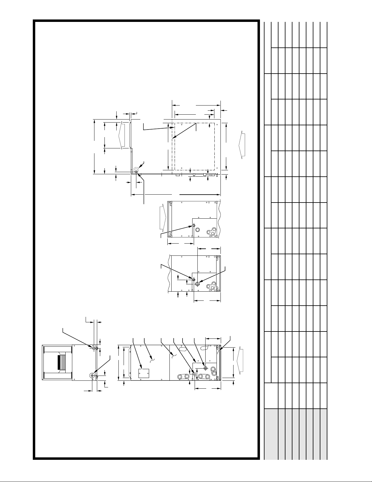
TOP VIEW
Dimensions
4
4
LIQUID LINE
CONNECTION
″
″
16
16
⁄
⁄
1
11
3
4
1″
″
8
⁄
3
″, 2″ DIA KNOCKOUTS
1
32
⁄
3
″, 1
8
⁄
FOR HIGH VOLTAGE POWER WIRING
7
DISCONNECT OR CIRCUIT
BREAKER LOCATION
BLOWER, CONTROL, & ELECTRIC
HEATER ACCESS PANEL
COIL ACCESS PANEL
LIQUID LINE
CONNECTION
FITTING
PANEL
″
4
⁄
3
10
″
⁄
SUCTION LINE
3
CONNECTION
6
16
B
C
″
16
⁄
″
8
⁄
7
1
″
15
16
⁄
1
15
5″
″
8
⁄
5
2
″
16
⁄
7
10
SLOPE COIL DETAILS
CONNECTION LOCATIONS
SHOWN FOR UPFLOW
OR HORIZ LEFT APPLICATIONS
FILTER ACCESS
PANEL
D
INLET AIR
OPENING
DETAILS CONNECTION LOCATIONS
FRONT VIEW SHOWN WITH "A" COIL
1″
FOR UPFLOW OR HORIZ APPLICATIONS
ABCDEH†J
In. mm In. mm In. mm In. mm In. mm In. mm In. mm
COIL
TYPE
UNIT
SIZE*
Slope 42-11/16 1084.3 14-5/16 363.5 12-7/16 316.0 12-5/16 312.7 10-7/16 265.1 — — 12.0 304.8
018, 024
Slope 47-11/16 1211.5 17-5/8 447.5 15-3/4 400.1 15-5/8 396.9 15-3/8 390.5 — — 17.0 431.8
030
Slope 49-5/8 1260.5 17-5/8 447.5 15-3/4 400.1 15-5/8 396.9 15-3/8 390.5 — — 17.0 431.8
036
Slope 53-7/16 1357.3 21-1/8 536.5 19-1/4 489.0 19-1/8 485.8 19-3/16 487.0 28-5/16 719.1 19.0 482.6
042
A 49-5/8 1260.5 21-1/8 536.5 19-1/4 489.0 19-1/8 485.8 15-11/16 398.3 24-1/2 622.3 — —
048
A 53-7/16 1357.3 21-1/8 536.5 19-1/4 489.0 19-1/8 485.8 19-1/2 495.3 28-5/16 719.1 — —
038, 060
A 59-3/16 1503.4 24-11/16 627.0 22-3/4 577.9 22-11/16 576.2 25-1/4 641.5 34-1/16 865.2 — —
054, 070
* Descriptions and dimensions apply to all versions (FA4A, FB4A, and FC4B), unless otherwise specified.
† Applicable for modular units only.
⁄16″
3
2
TYP
(2 PLACES)*
AIRFLOW
SLOPE COIL
″
16
⁄
7
AIRFLOW
TYP
(4 PLACES)*
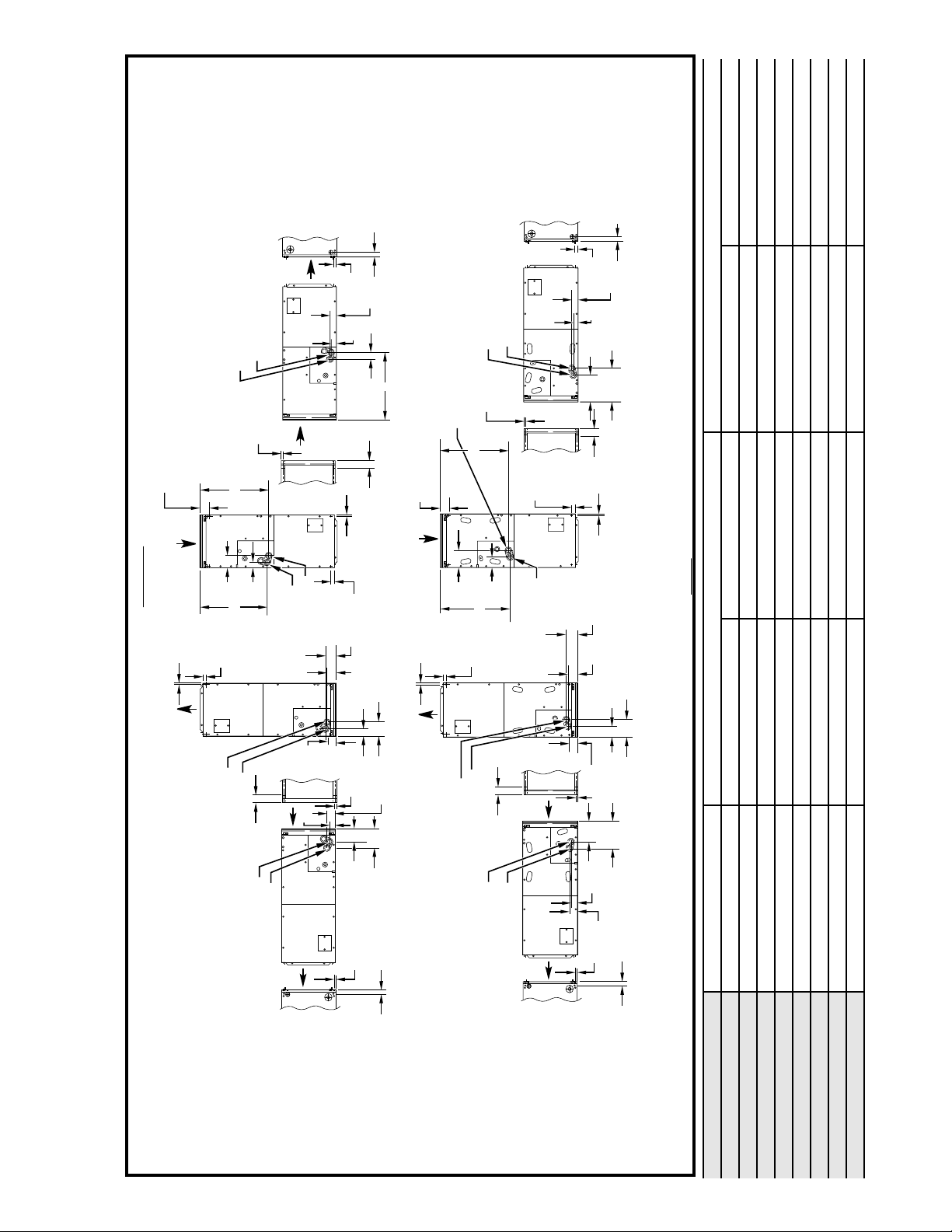
PRIMARY DRAIN
SECONDARY DRAIN
5
G
″
″
4
⁄
16
⁄
1
5
3
1
F
1″
TYP
(2 PLACES)*
″
PRIMARY DRAIN
16
⁄
13
1
SECONDARY DRAIN
″
16
⁄
TYP*
PRIMARY DRAIN
SECONDARY DRAIN
″
16
⁄
3
2
″
16
⁄
3
1
TYP*
PRIMARY DRAIN
SECONDARY DRAIN
TYP*
(2 PLCS)
″
2
⁄
1
″
16
⁄
5
1
″
16
/
7
TYP
1″
″
8
⁄
7
2
″
8
⁄
5
2
″
16
⁄
5
″
8
⁄
7
2
″
2
⁄
1
″
8
⁄
TYP*
7
″
TYP*
16
⁄
11
1
2″
F
″
16
⁄
13
TYP*
1
(4 PLACES)*
TYP
(2 PLACES)*
″
4
⁄
″
1
2
⁄
2
1
1
″
16
⁄
TYP*
11
1
5″
″
8
⁄
TYP*
7
HORIZ RIGHT
(FIELD CONVERTED)
″
16
⁄
3
2
TYP
(2 PLACES)*
AIRFLOW
DOWNFLOW
(FIELD CONVERTED)
″
16
⁄
TYP
(4 PLACES)*
7
UPFLOW
(AS SHIPPED)
AIRFLOW
HORIZ LEFT
(AS SHIPPED)
TYP*
PRIMARY DRAIN
″
16
⁄
TYP*
5
SECONDARY DRAIN
G
″
″
4
8
⁄
⁄
3
1
4
3
F
1″
TYP
(2 PLACES)*
PRIMARY DRAIN
13
SECONDARY DRAIN
PRIMARY DRAIN
SECONDARY DRAIN
1″
TYP
PRIMARY DRAIN
″
16
⁄
TYP*
1
SECONDARY DRAIN
(2 PLACES)*
″
2
⁄
1
TYP*
″
4
⁄
1
1
″
8
⁄
7
5
″
16
⁄
13
1
″
16
⁄
7
3″
″
16
⁄
11
2
″
16
⁄
3
TYP
2
″
16
⁄
5
″
8
⁄
7
5
″
4
⁄
1
1
″
2
⁄
1
1
″
2
⁄
1
″
8
⁄
TYP*
7
″
2
⁄
1
1
″
8
⁄
7
7
TYP*
TYP
(4 PLACES)*
″
4
⁄
″
3
8
⁄
4
1
3
(2 PLACES)*
TYP*
″
8
⁄
7
7
TYP*
A95531
HORIZ RIGHT
(FIELD CONVERTED)
DOWNFLOW
(FIELD CONVERTED)
A–COIL
UPFLOW
(AS SHIPPED)
HORIZ LEFT
(AS SHIPPED)
In. mm In. mm
A 23-7/16 593.3 23-1/8 587.4
A 27-1/4 692.2 26-15/16 684.2
Slope 18-1/8 460.4 18-5/8 473.1
Slope 23-1/8 587.4 23-5/8 600.0
Slope 23-1/8 587.4 23-5/8 600.0
Slope 26-15/16 684.2 27-1/2 698.5
A 32-15/16 836.6 32-5/8 828.7
Dimensions continued
PANEL, AND BACK OF CABINET. IN CABINET BOTTOM, HOLES PROVIDED
.136 IN. DIA. HORIZONTAL HANGING HARDWARE TO BE FIELD
SUPPLIED.
* HORIZONTAL MOUNT LOCATIONS - DIMPLES PROVIDED IN TOP
″
8
⁄
7
TYP*
030
036
042
018, 024
UNIT SIZE* COIL TYPE F G
048
038, 060
054, 070
otherwise specified.
* Descriptions and dimensions apply to all versions (FA4A, FB4A, and FC4B), unless
5
 Loading...