

Carrier 58STX09010016, 58STX11010012, 58STX09010014, 58STX07010016, 58STX07010012 Installation Guide
...
Single-Stage Deluxe
Induced-Combustion
4-W M lti i F rn
Cancels: II 310A-45-5 II 310A-45-6
4-06
installation,
Service and
Start-up, Operating, and
Maintenance instructions
Series 120/C
NOTE: Read tile entire instruction manual belk_re starting the
installation.
This symbol --> indicates a change since tile last issue.
--> Portions ol the Icxt and tables are reprinted hom NFPA 541ANSI Z223.1-2002©,
with permission ol National Fire Protection Association, Quincy, MA 02269 and
American Gas Association, Washington DC 20001. This rcprinlcd Inalcrial is IIot the
complete and oll]cial position ol the NFPA or ANSI on the relcrenced subject, which
is represented only by the standard in its entirety.
TABLE OF CONTENTS
SAFETY CONSIDERATIONS ..................................................... 2
INTRODUCTION .......................................................................... 3
CODES AND STANDARDS ........................................................ 3
Sali:ty ......................................................................................... 3
General Installation ................................................................... 5
Combustion and Ventilation Air .............................................. 5
Duct Systems ............................................................................ 5
Acoustical Lining and Fibrous Glass Duct .............................. 5
Gas Piping and Gas Pipe Pressure Testing .............................. 5
Electrical Connections .............................................................. 5
ELECTROSTATIC DISCHARGE (ESD) PRECAUTIONS
PROCEDURE ................................................................................ 5
LOCATION .................................................................................... 5
General ...................................................................................... 5
Location Relative to Cooling Equipment ................................ 7
AIR FOR COMBUSTION AND VENTILATION ...................... 7
INSTALLATION ......................................................................... 1I)
l.Jpflow Installation ................................................................. 10
Bottom Return Air Inlet .................................................... lI)
Side Return Air Inlet ......................................................... lI)
Leveling Legs (If Desired) ................................................ lI)
Downflow Installation ............................................................ 10
Bottom Return Air Inlet .................................................... 11
Horizontal Installation ............................................................ 12
Suspended Unit Support .................................................... 12
Platlk_rm Unit Support ....................................................... 12
Roll-Out Protection ............................................................ 12
Bottom Return Air Inlet .................................................... 13
Side Return Air Inlet ......................................................... 13
Filter Arrangement .................................................................. 13
Air Ducts ................................................................................. 13
General Requirements ....................................................... 13
Ductwork Acoustical Treatment .......................................13
Supply Air Connections .................................................... 13
Return Air Connections ..................................................... 14
EFFiCiENCY
CERTiFiED
Gas Piping ............................................................................... 17
Electrical Connections ............................................................ 19
115-V Wiring ..................................................................... 19
J-Bnx Relocation ............................................................... 20
Electrical Connection to J-Box ......................................... 20
Power Cord Installation ..................................................... 21
BX Cable Installation ........................................................ 21
24-V Wiring ....................................................................... 21
Accessories ........................................................................ 21
Venting .................................................................................... 23
General Venting Reqnirements ......................................... 23
Masonry Chimney Requirements ...................................... 23
Appliance Application Requirements ............................... 24
Additional Venting Requirements ..................................... 26
Sidewall Venting ............................................................... 27
START-UP, ADJUSTMENT, AND SAFETY CHECK ............ 27
General .................................................................................... 27
Start-Up Procedures ................................................................ 31
Adjustments ............................................................................. 31
Check Salety Controls ............................................................ 34
Checklist .................................................................................. 35
SERVICE AND MAINTENANCE PROCEDURES .................. 35
Introduction ............................................................................. 38
General ............................................................................... 38
Electrical Controls and Wiring ......................................... 38
Care and Maintenance ............................................................ 41
Cleaning and/or Replacing Air Filter ............................... 42
Blower Motor and Wheel .................................................. 42
Cleaning Heat Exchanger .................................................. 43
Sequence of Operation ............................................................ 44
Wiring Diagrams ..................................................................... 45
Troubleshooting ...................................................................... 45
Manufacturer reserves the right to discontinue, or change at any time, specifications or designs without notice and without incurring obligations.
PC 101 Printed in U.S.A. Pg 1 4-06
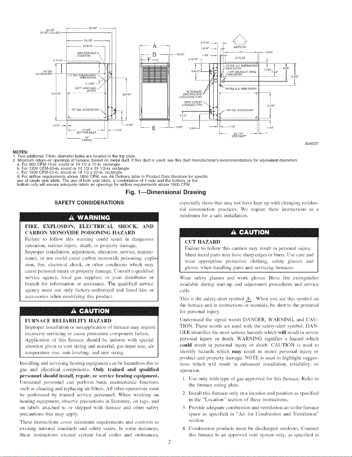
26-1/8"
(FLUE COLLAR)
-- 25-1/4" --
ACCESSORY
7/8" DIA I
5-15/16" ......
33-5/16"
11/16"--
-- 22-9/16" --
JUNCTION BOXm
LOCATION i;
112" DEATHERMOSTAT ....
WIRE ENTRY _*
3-15116" i_ ........
LEFT HAND GASS
ENTRY
7/8" D[A ACCESSORY_
21-5/8"
BOTTOM FNLET
__ 24 _ __
CASENG
_1-11/16"
l
i
i
24-7/8"
5-1/2"
A
AIRFLOW
D
OUTLET j
7-3/4"
f
LOCATFONS (TYP)
5 PLACES (TYP)
5-1/21'
11/16"
22-1/16"
SIDEINLET
14W/8"
1-1/4"
NOTES:
1. Two additional 7/8-in.diameter holes are located in the top plate.
2. Minimum return-air openings at furnace, based on metal duct. If flex duct is used, see flex duct manufacturer's recommendationsfor equivalent diameters.
a. For 800 CFM-16-in. round or 14 1/2 x 12-in. rectangle.
b. For 1200 CFM-20-in. round or 14 1/2 x 19 1/2-in. rectangle.
c. For 1600 CFM-22-in. round or 14 1/2 x 22-in. rectangle.
d. For airflow requirements above 1800CFM, see Air Deliverytablein Product Data literature for specific
use of single side inlets. The use of both side inlets, a combination of 1 side and the bottom or the
bottom only will ensureadequate return air openings for airflow requirements above 1800CFM.
Fig. 1--Dimensional Drawing
SAFETY CONSIDERATIONS
especially those that may not have kept up with changing residen-
tial construction practices. We require these instructions as a
nfininnnu for a safe installation.
A04037
FIRE, EXPLOSION, ELECTRICAL SHOCK, AND
CARBON MONOXIDE POISONING HAZARD
Failure to lk_llow this warning could result in dangerous
operation, serious injury, death, or properly damage.
hnproper installation, adjustment, alteration, service, mainte-
nance, or use could cause carbon monoxide poisnning, explo
sion, fire, electrical shock, or other conditions which may
cause personal injury or property damage. Consult a qualilied
service agency, local gas supplier, or your distributor or
branch lor inlormation or assistance. The qualified service
agency nmst use only factory-authorized and listed kits or
accessnries when modif_¢ing this product.
FURNACE RELIABILITY HAZARD
hnproper installation or misapplication of furnace may require
excessive servicing or cause premature component failure.
Application of this furnace should be indoors with special
attention given to vent sizing and material, gas input rate, air
temperature rise, unit leveling, and unit sizing.
Installing and servicing heating equipment can be hazardous due to
gas and electrical components. Only trained and qualified
personnel should install, repair, or service heating equipment.
Untrained personnel can perlkmn basic maintenance limctions
such as cleaning and replacing air filters. All other operations nmst
be perlbrmed by trained service personneh When working on
heating equipment, observe precautions in literature, on tags, and
on labels attached to or shipped with furnace and other salety
precautions that may apply.
These instructions cover mininmm requirements and conlorm to
existing national standards and salety codes. In some instances,
these instructions exceed certain local codes and ordinances,
CUT HAZARD
Failure to lollow this caution may result in personal injury.
Sheet metal parts may have sharp edges or burrs. Use cam and
wear appropriate protective clothing, sali_ty glasses and
gloves when handling parts and servicing lilrnaces.
Wear salety glasses and work gloves. Have fire extinguisher
available during start-up and adjustment procedures and service
calls.
This is the sali:ty-alert symbol Z_ • When you see this symbol on
the flmmce and in instructions or manuals, be alert to the potential
lk>r personal injury.
Understand the signal words DANGER, WARNING, and CAU-
TION. These words are used with the sali:ty-alert symboh DAN-
GER identifies the most serious hazards which will result in severe
personal injury or death. WARNING signifies a hazard which
could result in personal injury or death. CAUTION is used to
identify hazards which may result in minor personal injury or
product and property damage. NOTE is used to highlight sugges-
tions which will result in enhanced installation, reliability, or
operation.
1. Use only with type of gas approved lk)r this furnace. Reli:r to
the furnace rating plate.
2. Install this furnace only in a location and position as specified
in the "Location" section of these instructions.
3. Provide adequate combustion and ventilation air to the furnace
space as specified in "Air liar Combustion and Ventilation"
section.
4. Combustion products nmst be discharged outdoors. Connect
this furnace to an approved vent system only, as specilied in
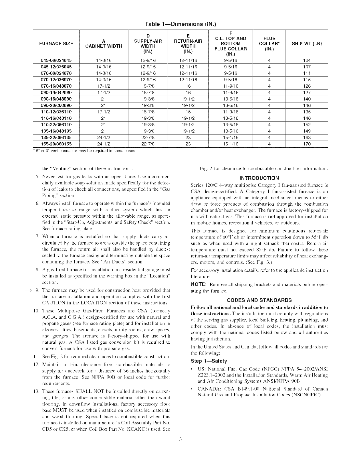
FURNACE SIZE
045-08/024045
045-12/036045
070-08/024070
070-12/038070
070-16/048070
090-14/042090
090-16/048090
090-20/060090
110-12/036110
110-16/048110
110-22/066110
135-16/048135
135-22/066135
155-20/060155
* 5"
or 6" vent connector may be required in some cases.
A
CABINET WIDTH
14-3/16
14-3/16
14-3/16
14-3/16
17-1/2
17-1/2
21
21
17-1/2
21
21
21
24-1/2
24-1/2
Table liDimensions (IN.)
D
SUPPLY-AIR
WIDTH
(IN.)
12-9/18
12-9/18
12-9/18
12-9/18
15-7/8
15-7/8
19-3/8
19-3/8
15-7/8
19-3/8
19-3/8
19-3/8
22-7/8
22-7/8
E
RETURN-AIR
WIDTH
(IN,)
12-11/18
12-11/18
12-11/18
12-11/18
18
18
19-1/2
19-1/2
18
19-1/2
19-1/2
19-1/2
23
23
F
C.L. TOP AND
BOTTOM
FLUE COLLAR
(IN,)
9-5/18
9-5/18
9-5/18
9-5/18
11-9/16
11-9/16
13-5/16
13-5/16
11-9/16
13-5/16
13-5/16
13-5/16
15-1/16
15-1/16
FLUE
COLLAR*
(IN.)
4
4
4
4
4
4
4
4
4
4
4
4
4
4
SHIP WT (LB)
104
107
111
115
128
127
140
148
135
148
152
149
163
170
the "Venting" section of these instructions.
5. Never test lbr gas leaks with an open flan_e. Use a commer-
cially available soap solution made specifically lbr the detec-
tion of leaks to check all connections, as speci{]ed in the "Gas
Piping" section.
6. Always install lilrnace to operate within the limlace's intended
temperature-rise range with a duct system which has an
external static pressure within the allowable range, as speci-
lied in the "Start-Up, Adjustments, and Salbty Check" section.
See furnace rating plate.
7. When a lklrnace is installed so that supply ducts carry air
circulated by the luruace to areas outside the space containing
the luruace, the return air shall also be handled by duct(s)
sealed to the Rirnace casing and terminating outside the space
containing the furnace. See "Air Ducts" section.
8. A gas-fired furnace lor installation in a residential garage nmst
be installed as specified in the warning box in the "Location"
section.
9. The fl]ruace may be used lot construction heat provided that
the fllrnace installation and operation complies with the lh'st
CAUTION in the LOCATION section of these instructions.
10. These Multipoise Gas-Fired Furnaces are CSA (lbrmerly
A.G.A. and C.G.A.) design-certified li._r use with natural and
propane gases (see Rirnace rating plate) and lbr installation in
alcoves, attics, basements, closets, utility rooms, crawlspaces,
and garages. The Rirnace is factory-shipped lbr use with
natural gas. A CSA listed gas conversion kit is required to
convert limmce lbr use with propane gas.
11. See Fig. 2 lbr required clearances to combustible construction.
12. Maintain a 1-in. clearance from combustible materials to
supply air ductwork lbr a distance of 36 inches horizontally
li"om the furnace. See NFPA 90B or local code lbr lurther
requirements.
13. These l_.lrnaces SHALL NOT be installed directly on carpet-
ing, tile, or any other combustible material other than wood
flooring. In downflow installations, factory accesso U floor
base MUST be used when installed on combustible materials
and wood flooring. Special base is not required when this
lurnace is installed on manulhcturer's Coil Assembly Part No.
CD5 or CK5, or when Coil Box Part No. KCAKC is used. See
Fig. 2 l_}l+clearance to combustible construction inlbrmation.
INTRODUCTION
Series 120/C 4 way nmltipoise Category I fan-assisted l_.ll'nace is
CSA design-certified. A Category I lhn-assisted furnace is an
appliance equipped with an integral mechauical means to either
draw or lorce products of conlbustion through the combustion
chamber and/or heat exchanger. The furnace is factory-shipped lot
use with natural gas. This furnace is not approved lbr installation
in mobile homes, recreational vehicles, or outdoors.
This lilrnace is designed for ndnimum continuous return-air
temperature of 60°F db or intermittent operation down to 55°F db
such as when used with a night setback thermostat. Return-air
temperature must not exceed 85°F db. Failure to lk_llow these
return-air temperature lindts may afilzct reliability of heat exchang-
ers, motors, and controls. (See Fig. 3.)
For accessory installation details, relbr to the applicable instruction
literature.
NOTE: Remove all shipping brackets and materials belk_m oper-
ating the lixrnace.
CODES AND STANDARDS
Follow all national and local codes and standards in addition to
these instructions. The installation must comply with regulations
of the serving gas supplier, local building, heating, plumbiug, and
other codes. In absence of local codes, the installation nmst
comply with the national codes listed below and all authorities
having jurisdiction.
In the United States and Canada, lbllow all codes and standards liar
the lollowing:
Step l iSafety
[IS: National Fuel Gas Code (NFGC) NFPA 54 2002/ANSI
Z223.1 2002 and the Installation Standards, Warm Air Heating
and Air Conditioning Systems ANS1/NFPA 90B
CANADA: CSA B149.1-00 National Standard of Canada
Natural Gas and Propane Installation Codes (NSCNGPIC)
INSTALLATION
MINIMUM INCHES CLEARANCE TO COMBUSTIBLE CONSTRUCTION
DISTANCE MINIMALE EN POUCES AUX CONSTRUCTIONS COMBUSTIBLES
This forced air furnace is equipped for use with This furnaceisapprovedfor UPFLOW,DOWNFLOW, and
natural gas at altitudes 0-10,000 fi (0-3,050m). HORIZONTALinsta]laiJons.
An accessory kit, supplied by the CettefoumaiseestapprouveepourI 'installationHORIZONTALE
manufacturer, shall be used to convert to propane etla circulationd'airVERS LEHAUTet VERSLEBAS.
gas use or may be required for some natural gas 1-...'_"b>
applications. Qearancearrows i'_r Lesfl6chesde degagement
This furnace is for indoor installation in a do notchangewith _ _ ! ne changepasavec
building con@'ucted on site.
This furnace may be instatfad on cornbustibfa _ !!
flooring in alcove or closet at minimum clearance
aSmateriaLindicatedby the diagram from combusitbfa X_AR_ _ _._ .U/
Tbls furnace may be used with a Type BH Vent .._-..L,._ERE_.." _ _
and may be vented in common with other gas ._ _. _ _._b
fired appliances. "'_£ _ r"_
pour utilbation avec gaz naturel et altitudes
comprises enb'e 0-3,050m (0H0,000 P0-
Utiliser une trousse de COnversion, fourble par
Cette fournaise a air pulse est equip6e ? _
fa fabdcant, pour passer au gaz propane ou pour
certaines installations au gaz natureL ""
Cette fuurnaise est pr6vue pour eb-e N,_ 8_ V"
fastallee darts un b_timent construit sur place. _ _ _ Clearancein inches
Cette fournaise peut 6b'e instatlee sur _ / Degagement(po).
un plancher combustible dans une alc6ve ou
darts un garde_robe en respectant fa minimum
d'espace libre des mat@iaux combustibfas, tel Vent Clearance to combustibles:
qulndique sur fa diagramme. ForSingleWail venis6 inches(6po).
Cette foumaise peut _tre uti[isee ave(; un ForType B-1venttype 1inch(1po).
conduit d'evacuation de Type Bq ou connectee Pourcondui_d'evacuationa paroisimple6po (6 inches).
au conduit ommun d 'autres appareils a gaz. Pourconduitd'evacuationdeType B:I 1_o(1
tumaceorientation. _ _ I I 'orientationde la foumaise.
Degagement de l'@ent avec combustibles:
MINIMUM INCHES CLEARANCE TO COMBUSTIBLE CONSTRUCTION
DOWNFLOWPOSITIONS:
1- thstallation on non-combusfaible floors only.
For Installation on combestible flooring only when installed on special base, Part No. KGASB0201ALL
Coil Assembly, Part No. CD5 or CK5, or Coil Casing, Part No. KCAKC.
18 inches front cfaarance required for alcove.
-k Indicates supply or return sides when furnace is in the horizontal position. Line contact only permissible
between lines formed by intersections of the Top and two Sides of the furnace jacket, and building joists,
studs or framing.
DF:GAGEMENT MINIMUM EN POUCES AVEC €:LEMENTS
DE CONSTRUCTION COMBUSTIBLES
POURLA POSITIONCOURANTDESCENDANT:
1- Pourl'instatlation sur plancher non combustible seulement.
Pour I1nstallation sur un piancher combustible seulement quand on utilise ta base speciafa, piece
no KGASB0201ALL I'ensembfa serpentin, piece no CD5 ou CK5 ou le carter de serpentin, piece
no KCAKC.
O Dans une alc6ve, on doit maintenir undegagement a Favant de 18 po (450ram).
-k La poistion fadiquee concerne le c6t6 d'entree ou de retour quand lafournaise est dans la
position horizontafa.
Le contact n'est permis qu'enb'e fas tignes formees par fas intersections du dessus et des
deux c6t6s de la cherdse dela fournaise et fas solives, montant sous cadre de charpente.
327590-101 REV. C
Fig. 2--Clearances to Combustibles
A04123
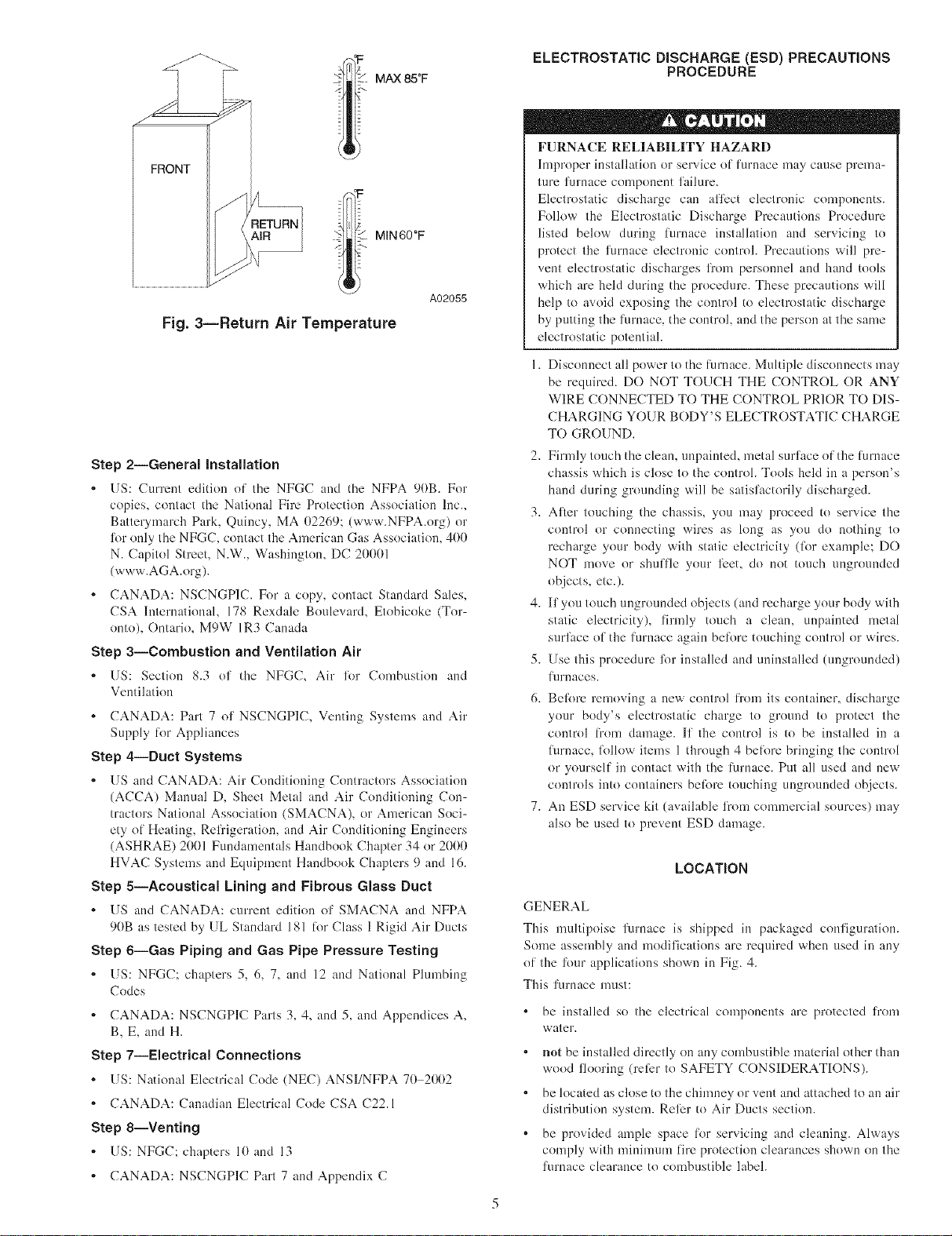
MAX 85°F
FRONT
/J MIN60OF
A02055
Fig. 3iReturn Air Temperature
Step 2iGeneral installation
• US: Current edition of tile NFGC and tile NFPA 9(lB. For
copies, contact the National Fire Protection Association Inc.,
Batterymarch Park, Quincy, MA 02269: (www.NFPA.org) or
%r only the NFGC, contact the American Gas Association, 400
N. Capitol Street, N.W., Washington, DC 2(t(t(tl
(www.AGA.org).
= CANADA: NSCNGP1C. For a copy, contact Standard Sales,
CSA International, 178 Rexdale Boulevard, Etobicoke (Tor-
onto), Ontario, M9W IR3 Canada
Step 3--Combustion and Ventilation Air
• US: Section 8.3 of the NFG(', Air %r Combustion and
Ventilation
• CANADA: Part 7 of NSCNGPIC, Venting Systems and Air
Supply lot Appliances
Step 4--Duct Systems
• [IS and CANADA: Air Conditioning Contractors Association
(ACCA) Manual D, Sheet Metal and Air Conditioning Con-
tractors National Association (SMACNA), or American Soci-
ety of Heating, Reli"igeration, and Air Conditioning Engineers
(ASHRAE) 2001 Fundamentals Handbook Chapter 34 or 2(t(t(t
HVAC Systems and Equipment Handbook Chapters 9 and 16.
Step 5iAcoustical Lining and Fibrous Glass Duct
• {IS and CANADA: current edition of SMACNA and NFPA
9(tB as tested by UL Standard 181 lor Class 1Rigid Air Ducts
Step 6iGas Piping and Gas Pipe Pressure Testing
• US: NFG('; chapters 5, 6, 7, and ]2 and National Plumbing
('odes
• CANADA: NSCNGPIC Parts 3, 4, and 5, and Appendices A,
B, E, and H.
Step 7--Electrical Connections
• US: National Electrical Code (NEC) ANSI/NFPA 70 2002
• CANADA: Canadian Electrical Code CSA C22.1
Step 8--Venting
, {IS: NFGC; chapters l(t and 13
= CANADA: NSCNGPIC Part 7 and Appendix C
ELECTROSTATIC DISCHARGE (ESD) PRECAUTIONS
PROCEDURE
FURNACE RELIABILITY HAZARD
hnproper installation or service of furnace may cause prema-
ture furnace component failure.
Electrostatic discharge can affect electronic components.
Follow the Electrostatic Discharge Precautions Procedure
listed below during fln'nace installation and servicing to
protect the furnace electronic controh Precautions will pre-
vent electrostatic discharges fl'om personnel and hand tools
which are held during the procedure. These precautions will
help to avoid exposing the control to electrostatic discharge
by putting the furnace, the control, and the person at the same
electrostatic potential.
1. Disconnect all power to the furnace. Multiple disconnects may
be required. DO NOT TOUCH THE CONTROL OR ANY
WIRE CONNECTED TO THE CONTROL PRIOR TO DIS-
CHARGING YOUR BODY'S ELECTROSTATIC CHARGE
TO GROUND.
2. Firmly touch the clean, unpainted, metal surface of the limmce
chassis which is close to the controh Tools held in a person's
band during grounding will be satisfactorily discharged.
3. After touching the chassis, you may proceed to service the
control or connecting wires as long as you do nothing to
recharge your body with static electricity (lbr example; DO
NOT move or shuffle your IL'et, do not touch ungrounded
objects, etc.).
4. If you touch ungrounded objects (and recharge your body with
static electricity), firndy touch a clean, unpainted metal
surlilce of the furnace again betk_retouching control or wires.
5. Use this procedure li)r installed and uninstalled (ungrounded)
lul'naces.
6. Belbm ren-ioving a new control li"om its container, discharge
your body's electrostatic charge to ground to protect the
control from damage. If the control is to be installed in a
lurnace, lbllow items 1 through 4 belore bringing the control
or yourself in contact with the limmce. Put all used and new
controls into containers belbm touching ungrounded objects.
7. An ESD service kit (available from commercial sources) may
also be used to prevent ESD damage.
LOCATION
GENERAL
This nmltipoise furnace is shipped in packaged configuration.
Some assembly and modifications are required when used in any
of the %ur applications shown in Fig. 4.
This furnace nmst:
be installed so the electrical components are protected from
water.
not be installed directly on any combustible material other than
wood flooring (reli:r to SAFETY CONSIDERATIONS).
be located as close to the chinmey or vent and attached to an air
distribution system. Reler to Air Ducts section.
be provided ample space lor servicing and cleaning. Always
comply with minimum fire protection clearances shown on the
furnace clearance to combustible label.
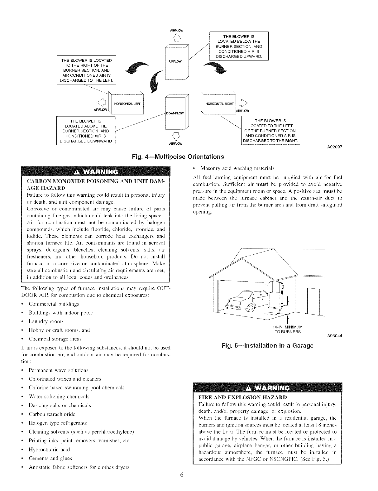
THE BLOWER IS LOCATED
TOTHE RIGHT OF THE
BURNER SECTION, AND
AIR CONDITIONED AIR IS
DISCHARGED TO THE LEFT.
AIRFLOW
THE BLOWER IS
LOCATED BELOW THE
BURNER SECTION, AND
CONDITIONED AIR IS
DISCHARGED UPWARD.
2!
THE BLOWER IS
LOCATED ABOVE THE
BURNER SECTION, AND
CONDITIONED AIR IS
DISCHARGED DOWNWARD
Fig. 4--Multipoise Orientations
CARBON MONOXIDE POISONING AND UNIT DAM-
AGE HAZARD
Failure to lollow this warning could result in personal injury
or death, and unit component damage.
Corrosive or contaminated air may cause failure of parts
containing flue gas, which could leak into the living space.
Air Ik_rcombustion must not be contaminated by halogen
compounds, which include fluoride, chloride, bromide, and
iodide. These elements can corrode heat exchangers and
shorten filrnace liii_. Air contaminants are Ik}und in aerosol
sprays, detergents, bleaches, cleaning solvents, salts, air
fresheners, and other household products. Do not install
flmmce in a corrosive or contanfinated atmosphere. Make
sure all combustion and circulating air requirements are met,
in addition to all local codes and ordinances.
..........................................._ HORIZO
q ..................................... IAIRFLOW
LOCATED TO THE LEFT
OF THE BURNER SECTION,
AND CONDITIONED AIR IS
TBEBLOWER,S
A02097
• Masonry acid washing materials
All fuel-burning equipment must be supplied with air R_r fuel
combustion. Sufficient air must be provided to avoid negative
pressure in the equipment room or space. A positive seal must be
made between the furnace cabinet and the return-air duct to
prevent pulling air fi'om the burner area and from dral) sali:guard
opening.
\
The Ikfllowing types of furnace installations may require OUT-
DOOR AIR lor combustion due to chemical exposures:
Connnercial buildings
Buildings with indoor pools
Laundry rooms
Hobby or cl'al_ rooms, and
Chendcal storage areas
If air is exposed to the lollowing substances, it should not be used
lkwcombustion air, and outdoor air may be required li)r combus-
tion:
Permanent wave solutions
Chlorinated waxes and cleaners
Chlorine based swinnning pool chemicals
Water soflening chendcals
De-icing salts or chemicals
Carbon tetrachloride
Halogen type refrigerants
Cleaning solvents (such as perchloroethylene)
Printing inks, paint removers, varnishes, etc.
Hydrochloric acid
Cements and glues
Antistatic fabric softeners liw clothes dryers
18-IN. MINIMUM
TO BURNERS
A93044
Fig. 5--Installation in a Garage
FIRE AND EXPLOSION HAZARD
Failure to lk)llow this warning could result in personal injury,
death, and/or property damage, or explosion.
When the furnace is installed in a residential garage, the
burners and ignition sources nmst be located at least 18 inches
above the floor. The l_rnace nmst be located or protected to
avoid damage by vehicles. When the furnace is installed in a
public garage, airplane hangar, or other building having a
hazardous atmosphere, the furnace must be installed in
accordance with the NFGC or NSCNGP1C. (See Fig. 5.)
PERSONAL INJURY AND/OR PROPERTY DAMAGE
HAZARD
hnproper use or installation of this furnace may cause
premature fl]rnace component failure.
This gas lurnace may be used %r heating buildings under
construction provided that:
-The furnace is permanently installed with all electrical
wiring, piping, venting and dncting installed according to
these installation instructions. A return air duct is pa)vided,
sealed to the lm'nace casing, and terminated outside the space
containing the lurnace. This prevents a negative pressure
condition as created by the circulating air blower, causing a
flame rollout and/or drawing combustion products into the
structure.
-The lilrnace is controlled by a thermostat. It may not be "hot
wired" to provide heat continuously to the structure without
thermostatic controh
-Clean outside air is provided %r combustion. This is to
minimize the corrosive el'li_cts of adhesives, sealers and other
construction materials. It also prevents the entrainment of
drywall dust into combustion air, which can cause flmling
and plugging of furnace components.
-The temperature of the return air to the li]rnace is maintained
between 55°F (13°C) and 80°F (27°C), with no evening
setback or shutdown. The use of the furnace while the
structure is under construction is deemed to be interndttent
operation per our installation instructions.
-The air temperature rise is within the rated rise range on the
lurnace rating plate, and the gas input rate has been set to the
nameplate value.
-The filters used to clean the circulating air during the
construction process nmst be either changed or thoroughly
cleaned prior to occupancy.
-The furnace, ductwork and filters are cleaned as necessary to
remove duwall dust and construction debris li"om all HVAC
system components after construction is completed.
-Verily proper limmce operating conditions including igni-
tion, gas input rate, air temperature rise, and venting accord-
ins to these installation instructions.
FIRE HAZARD
Failure to follow this warning could result in personal injury,
death andk)r property damage.
Do not install the furnace on its back or hang furnace with
control compartment facing downward. Sali_ty control opera-
tion will be adversely afli:cted. Never connect return-air ducts
to the back of the furnace. (See Fig. 6.)
LOCATION RELATIVE TO COOLING EQUIPMENT
The cooling coil n]ust be installed parallel with, or on the
downstream side of the unit to avoid condensation in the heat
exchangers. When installed parallel with the furnace, dampers or
other flow control n]ust prevent chilled air li"om entering the
furnace. If the dampers are manually operate& they must be
equipped with means to prevent operation of either unit unless the
damper is in the full-heat or lull-cool position.
BACK
A02054
Fig. 6--Prohibit Installation on Back
AIR FOR COMBUSTION AND VENTILATION
Provisions lot adequate combustion, ventilation, and dilution air
nmst be provided in accordance with:
U.S. installations: Section 8.3 of the NFGC, Air %r Combus-
tion and Ventilation, and applicable provisions of the local
building codes.
Canadian installations: Part 7 of the NSCNGPIC, Venting
Systems and Air Supply lbr Appliances, and all authorities
having jurisdiction.
FURNACE CORROSION HAZARD
Faihn'e to lbllow this caution may result in furnace damage.
Air [or combustion nn]st not be contaminated by halogen
compounds_ which inch]de fluoride, chloride, bromide_ and
iodide. These elements can corl:ode heat exchangers and
shorten furnace lili:. Air contaminants are flmnd in aerosol
sprays, detergents, bleaches, cleaning solvents, salts, air
li"esheners, and other household products.
CARBON MONOXIDE POISONING HAZARD
Faih]re to follow this warning could result in personal injury
or death.
The operation of exhaust fans, kitchen ventilation fans,
clothes dryers, attic exhaust fans or fireplaces could create a
NEGATIVE PRESSURE CONDITION at the li;rnace.
Make-up air MUST be provided li)r the ventilation devices, in
addition to that required by the fln'nace. Reli:r to Carbon
Monoxide Poisoning Hazard warning in venting section of
these instructions to determine if an adequate amount of
make-up air is available.
The requirements %r combustion and ventilation air depend upon
whether or not the lurnace is located in a space having a volume
of at least 50 cubic licet per 1,000 Btuh input rating lbr all gas
appliances installed in the space.
Spaces having less than 50 cubic li_et per 1,000 Btnh require
the OUTDOOR COMBUSTION AIR METHOD.
Spaces having at least 50 cubic li_etper 1,000 Btuh may use the
INDOOR COMBUSTION AIR, STANDARD or KNOWN-
AIR INFILTRATION METHOD.
Outdoor Combustion Air Method
1. Provide the space with sufficient air %r proper combustion,
ventilation, and dilution of flue gases using permanent hori-
zontal or vertical duct(s) or opening(s) directly comnmnicat-
ins with the outdoors or spaces that freely commmficate with
the outdoors.
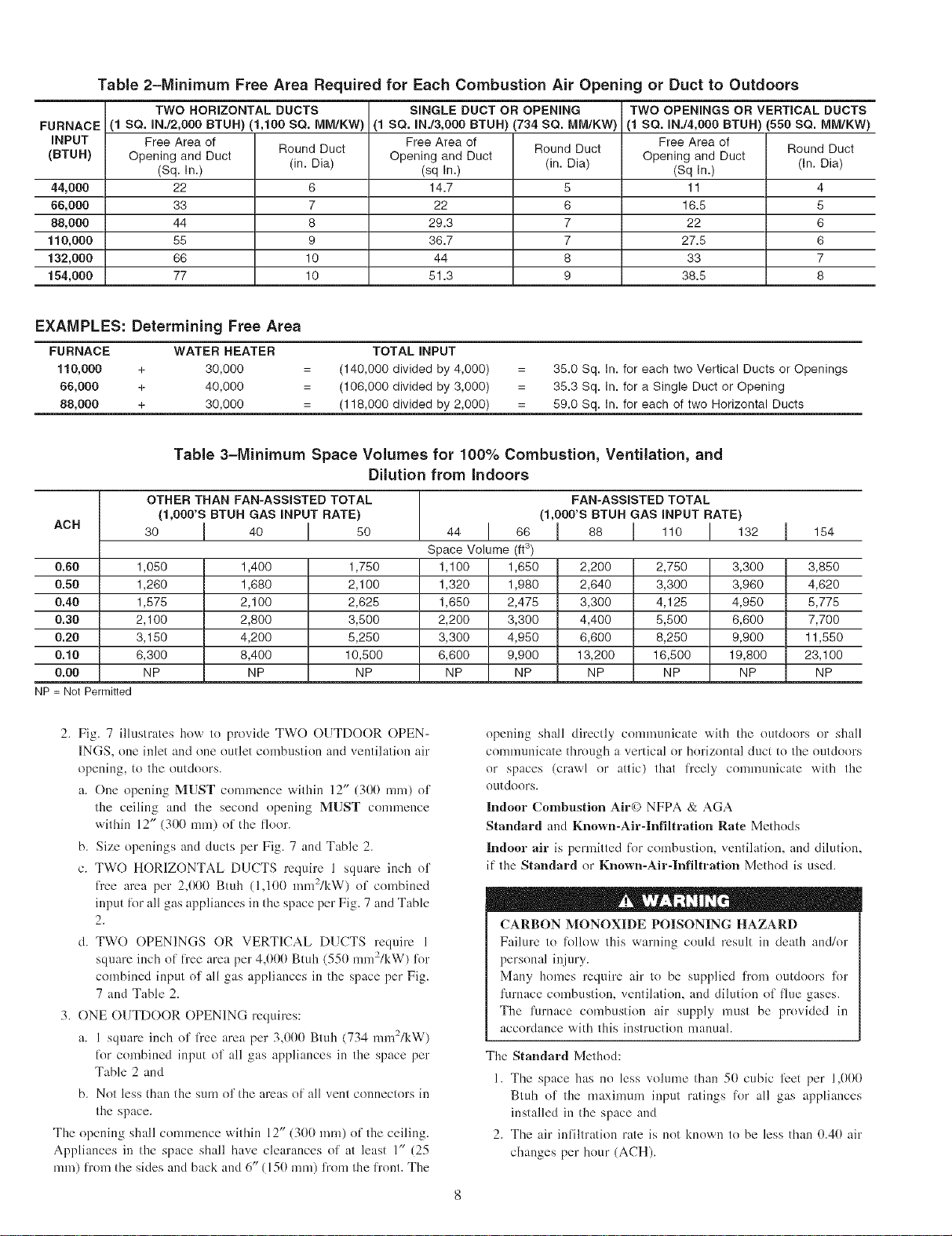
Table 2-Minimum Free Area Required for Each Combustion Air Opening or Duct to Outdoors
TWO HORIZONTAL DUCTS SINGLE DUCT OR OPENING TWO OPENINGS OR VERTICAL DUCTS
FURNACE (1 SQ. IN./2,000 BTUH) (1,100 SQ. IvIM/KW) (1 SQ. IN./3,000 BTUH) (734 SQ. MM/KW) (1 SQ. IN./4,000 BTUH) (550 SQ. IvIM/KW)
iNPUT Free Area 01 Free Area 01 Free Area of
(BTUH) Opening and Duct Round Duct Opening and Duct Round Duct Opening and Duct Round Duct
44,000 22 6 14.7 5 11 4
66,000 33 7 22 6 16.5 5
88,000 44 8 29.3 7 22 6
110,000 55 9 36.7 7 27.5 6
132,000 66 10 44 8 33 7
154,000 77 10 51.3 9 38.5 8
(Sq. In.) (in. Dia) (sq In.) (in. Dia) (Sq In.) (In. Dia)
EXAMPLES: Determining Free Area
FURNACE WATER HEATER TOTAL INPUT
110,000 + 30,000 (140,000 divided by 4,000) 35.0 Sq. In. for each two Vertical Ducts or Openings
66,000 + 40,000 (106,000 divided by 3,000) 35.3 Sq. In. for a Single Duct or Opening
88,000 + 30,000 (118,000 divided by 2,000) 59.0 Sq. In. for each of two Horizontal Ducts
Table 3-Minimum Space Volumes for 100% Combustion, Ventilation, and
Dilution from Indoors
OTHER THAN FAN=ASSiSTED TOTAL FAN-ASSISTED TOTAL
ACH
0.60 1,050 1,400 1,750 1,100 1,650 2,200 2,750 3,300 3,850
0.50 1,260 1,680 2,100 1,320 1,980 2,640 3,300 3,960 4,620
0.40 1,575 2,100 2,625 1,650 2,475 3,300 4,125 4,950 5,775
0.30 2,100 2,800 3,500 2,200 3,300 4,400 5,500 6,600 7,700
0.20 3,150 4,200 5,250 3,300 4,950 6,600 8,250 9,900 11,550
0.10 6,300 8,400 10,500 6,600 9,900 13,200 16,500 19,800 23,100
0.00 NP NP NP NP NP NP NP NP NP
NP = Not Permitted
{1,000'S BTUR GAS iNPUT RATE) (1,000'S BTUR GAS iNPUT RATE)
30 I 40 ! 50 44 ! 66 I 88 I 110 ! 132 I 154
Space Volume (ft3)
2. Fig. 7 illustrates how to provide TWO OUTDOOR OPEN-
INGS, one inlet and one outlet combustion and ventilation air
opening, to the outdoors.
a. One opening MUST commence within 12" (300 ram) of
the ceiling and the second opening MUST colnmence
within 12" (300 rain) of the floor.
b. Size openings and ducts per Fig. 7 and Table 2.
c. TWO HORIZONTAL DUCTS require 1 square inch of
free area per 2,000 Btuh (l,lO0 nnn2/kW) of cembined
input R)r all gas appliances in the space per Fig. 7 and Table
2.
d. TWO OPENINGS OR VERTICAL DUCTS require 1
square inch ol free area per 4,000 Btuh (. 50 mm-/l<W) l_r
combined input of all gas appliances in the space per Fig.
7 and Table 2.
3. ONE OUTDOOR OPENING requires:
a. 1 square inch of free area per 3,000 Bmh (734 elnl2/kW)
liar combined input of all gas appliances in the space per
Table 2 and
b. Not less than the sum of the areas ef all vent connectors in
the space.
The opening shall commence within 12" (300 nnn) of the ceiling.
Appliances in the space shall have clearances of at least l" (25
ram) l_'om the sides and back and 6" (150 nnn) from the l_'ont. The
opening shall directly comnmnicate with the outdoors or shall
communicate thamgh a vertical or horizontal duct to the outdoors
er spaces (crawl or attic) that l]'eely conmmnicate with the
eutdoors.
Indoor Combustion Air{) NFPA & AGA
Standard and Known-Air-Infiltration Rate Methods
Indoor air is permitted R)r combustion, ventilatiom and dilution,
if the Standard or Known-Air-Infiltratlon Method is used.
CARBON MONOXIDE POISONING HAZARD
Failure to l%llow this warning could result in death and/or
personal injury.
Many homes require air to be supplied l]'om outdoors lk_r
furnace combustion, ventilation, and dilution of flue gases.
The furnace combustion air supply must be provided in
accordance with this instruction manual.
The Standard Method:
1. The space has no less vohnne than 50 cubic IL'et per l,I)I)I)
Btuh of the maxinmm input ratings lk)r all gas appliances
installed in the space and
2. The air infiltration rate is not known to be less than 0.40 air
changes per hour (ACH).
DUCTS
CIRCULATING AIR ]_l
I I I I I I
I I I I I I
I I I I I I
VENT THROUGH ROOF
12"MAX
1SQIN. A
PER 2000
BTUH*
T
[
DUCTS
TO
OUTDOORS
i SQIN.
PER 2000
BTUH* f
I, ii 12"MAX
CIRCULATING AIR DUCTS
*Minimum dimensions of 3 in.
NOTE: Use any of the following
combinations of openings:
A&B C&D D&E F&G
Fig. 7--Air for Combustion, Ventilation, and
Dilution for Outdoors
The Known Air Infiltration Rate Method shall be used, if the
irffiltration rate is known to be:
1. Less than 0.40 ACH and
2. Equal to or greater than 0.10 ACH
Infiltration rates greater dnm 0.60 ACH shall not be used. The
nfinimum required volume of tile space varies with the number of
ACH and shall be detemfined per Table 3 or Equations 1 and 2.
Determine tile minimum required volume %r each appliance in the
space and add the vohnnes together to get the total udnimum
required vohnne %r the space.
Tahle 3-Mininmm Space Volumes were determined by using the
fl}llowing equations fi'nm the National Fuel Gas Code ANSI
Z223.1-2002/NFPA .54-2002,8.3.2.2:
1. For other than fan-asslsted appliances, such as a drali
hood-equipped water heater:
-21ft3_ Iother ._
Volume Oth,_--A---"C-Hp0-0 B'iu/hFJ
2. For fan-assisted appliances such as this furnace:
-- 1S_t 3 I fan
DL_C_T_"-- 1SQIN.
TO PER 4000
OUTDOORS BTUH*
A03174
A04002
A04003
_< 12" AX
U-z -=--1SQ IN.
PER1000
OR WALL
TUH*,NDOOR
INTERIOR
HEATED
SPACE
IRCULATING AIR DUCTS
* Minimum opening size is 100 sq in. with
minimum dimensions of 3 in.
tMinimum of 3 in. when type-B1 vent is used.
l
Fig. 8--Air for Combustion, Ventilation, and
Dilution from Indoors
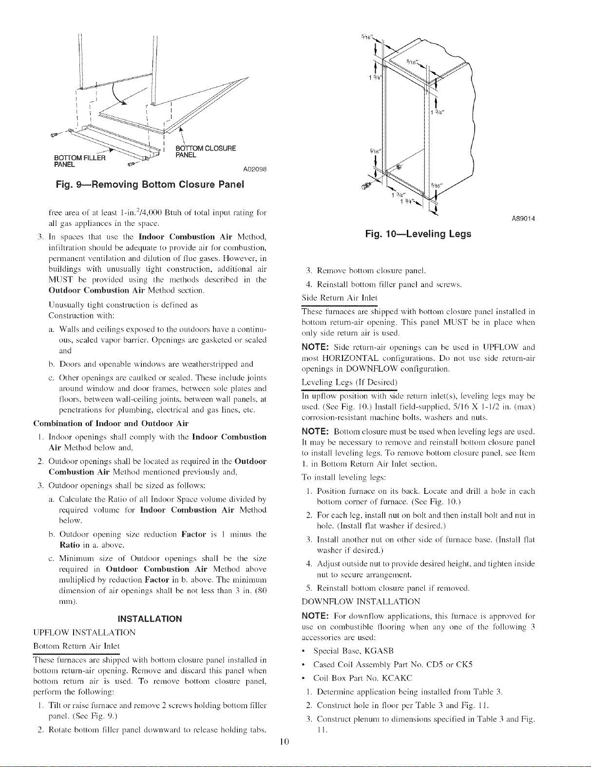
l[:
lo,,.. , = combined input ol' all other than fan-assisted appli-
ances in Btu/hr
lh, , = combined input of all fan-assisted appliances in Btu/hr
ACH = air changes per hour (ACH shall not exceed 0.60.)
The %llowing requirements apply to the Standard Method and to
the Known Air Infiltration Rate Method.
I. Adjoining rooms can be considered part of a space if:
a. There are no closable doors between l'ooms.
b. Combining spaces on same floor level. Each opening shall
have fi'ee area of at least 1 in.2/l,000 Btuh (2,000 mme/kW)
of the total input rating of all gas appliances ilk the space,
but net less than 100 in. 2 (0.06 m2). One opening shall
connnence within 12" (300 ram) of the ceiling and the
second opening shall commence within 12" (300 ram) of
the floor. The mininmm dimension of air openings shall be
at least 3 in. (80 ram). (See Fig. 8.)
c. Combining space on dilli:rent floor levels. The volumes of
spaces on difii:rent floor levels shall be considered as
communicating spaces if connected by one or more perma-
nent openings ilk deers or floors having l)'ee area of at least
2 in.2/l,000 Btah (4,400 mm2/kW) of total input rating of
all gas appliances.
2. An attic or crawlspace may be considered a space that freely
communicates with the outdoors provided there are adequate
permanent ventilation openings directly to outdoors having
UNCONFINED
6" MIN
! SPACE
(FRONT)t
z_ 1SQIN.
<Lu PER 1000
rr a_ BTUH* IN DOOR
<O __--ORWALL
iii
©
L12" MAX
A03175
BOTTOM CLOSURE
BO]qOM FILLER
PANEL
PANEL
Fig. 9--Removing Bottom Closure Panel
A02098
fi'ee area of at least l-in.2/4,000 Btuh of total input rating lot
all gas appliances in the space.
3. In spaces that use the Indoor Combustion Air Method,
infiltration should be adequate to provide air lor combustion,
permanent ventilation and dilntion of title gases. However, in
buildings with unusually tight constrnctiom additional air
MUST be provided using the methods described in the
Outdoor Combustion Air Method section.
Unusually tight construction is defined as
Construction with:
a. Walls and ceilings exposed to the outdoors have a continu-
ous, sealed vapor barrier. Openings are gasketed or sealed
and
b. Doors and openable windows are weatherstripped and
c. Other openings are caulked or sealed. These include joints
around window and door fi'ames, between sole plates and
floors, between wall-ceiling joints, between wall panels, at
penetrations lor plumbing, electrical and gas lines, etc.
Combination of Indoor and Outdoor Air
1. Indoor openings shall comply with the Indoor Combustion
Air Method below and,
2. Outdoor openings shall be located as required in the Outdoor
Comlmstlon Air Method mentioned previously and,
3. Outdoor openings shall be sized as lollows:
a. Calculate the Ratio of all Indoor Space volume divided by
required volume lot Indoor Combustion Air Method
below.
b. Outdoor opening size reduction Factor is 1 minus the
Ratio in a. above.
c. Minimum size of Outdoor openings shall be the size
required in Outdoor Combustion Air Method above
multiplied by reduction Factor in b. above. The ndnimum
dimension of air openings shall be not less than 3 in. (80
mm).
INSTALLATION
UPFLOW INSTALLATION
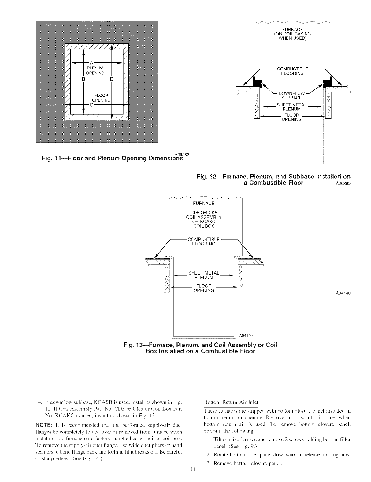
Bottom Return Air Inlet
These lurnaces are shipped with bottom closure panel installed in
bottom return-air opening. Remove and discard this panel when
bottom return air is used. To remove bottom closure panel,
perlorm the lollowing:
1. Tilt or raise furnace and remove 2 screws holding bottom filler
panel. (See Fig. 9.)
2. Rotate bottom filler panel downward to release holding tabs.
A89014
Fig. 10--Leveling Legs
3. Remove bottom closure panel.
4. Reinstall bottom filler panel and screws.
Side Return Air Inlet
These furnaces are shipped with bottom closure panel installed in
bottom return-air opening. This panel MUST be in place when
only side return air is used.
NOTE: Side return-air openings can be used in UPFLOW and
most HORIZONTAL configurations. Do not use side return-air
openings in DOWNFLOW configuration.
Leveling Legs (If Desired)
In upflow position with side return inlet(s), leveling legs may be
used. (See Fig. 111.) Install field-supplied, 5/16 X l-l/2 in. (max)
corrosion-resistant machine bolts, washers and nuts.
NOTE: Bottom closure must be used when leveling legs are used.
It may be necessary to remove and reinstall bottom closure panel
to install leveling legs. To remove bottom closure panel, see Item
1. in Bottom Return Air Inlet section.
To install leveling legs:
1. Position furnace on its back. Locate and drill a hole in each
bottom corner of furnace. (See Fig. 10.)
2. For each leg, install nut on bolt and then install bolt and nut in
bole. (Install flat washer if desired.)
3. Install another nut on other side of fiwnace base. (Install flat
washer if desired.)
4. Adjust outside nut to provide desired height, and tighten inside
nut to secure arrangement.
5. Reinstall bottom closure panel if removed.
DOWNFLOW INSTALLATION
NOTE: For downflow applications, this fllrnace is approved lor
use on combustible flooring when any one of the fl}llowing 3
accessories are used:
* Special Base, KGASB
* Cased Coil Assembly Part No. CD5 or CK5
° Coil Box Part No. KCAKC
1. Determine application being installed from Table 3.
2. Construct hole in floor per Table 3 and Fig. 11.
3. Construct plenum to dimensions speci/Sed in Table 3 and Fig.
11.
10
FURNACE
(OR COIL CASING
WHEN USED)
COMBUSTIBLE
FLOORING
SUBBASE
PLENUM
__ FLOOR __
OPENING
Fig. 11iFloor and Plenum Opening Dimensions
• . A96283
__ FLOOR
Fig. 12iFurnace, Plenum, and Subbase Installed on
a Combustible Floor A96285
FURNACE
CD5 OR CK5
COIL ASSEMBLY
OR KCAKC
COIL BOX
COMBUSTIBLE
FLOORING
SHEET METAL____=._
PLENUM
OPENING
A04140
Fig. 13--Furnace, Plenum, and Coil Assembly or Coil
Box Installed on a Combustible Floor
4. If downflow subbase, KGASB is used, install as shown in Fig.
12. If Coil Assembly Part No. CD5 or CK5 or Coil Box Part
No. KCAKC is used, install as shown in Fig. 13.
NOTE: It is recommended that the perlbrated supply-air duct
flanges be completely fblded over or removed li"om furnace when
installing the fimlace on a factory-supplied cased coil or coil box.
To remove the supply-air duct flange, use wide duct pliers or hand
seamers to bend flange back and lbrth until it breaks off. Be careful
of sharp edges. (See Fig. 14.)
A04140
Bottom Return Air Inlet
These furnaces are shipped with bottom closure panel installed in
bottom return-air opening. Remove and discard this panel when
bottom return air is used. To remove bottom closure panel,
perlbrm the lollowiug:
1. Tilt or raise furnace and remove 2 screws holding bottom filler
panel. (See Fig. 9.)
2. Rotate bottom filler panel downward to release holding tabs.
3. Remove bottom closure panel.
II
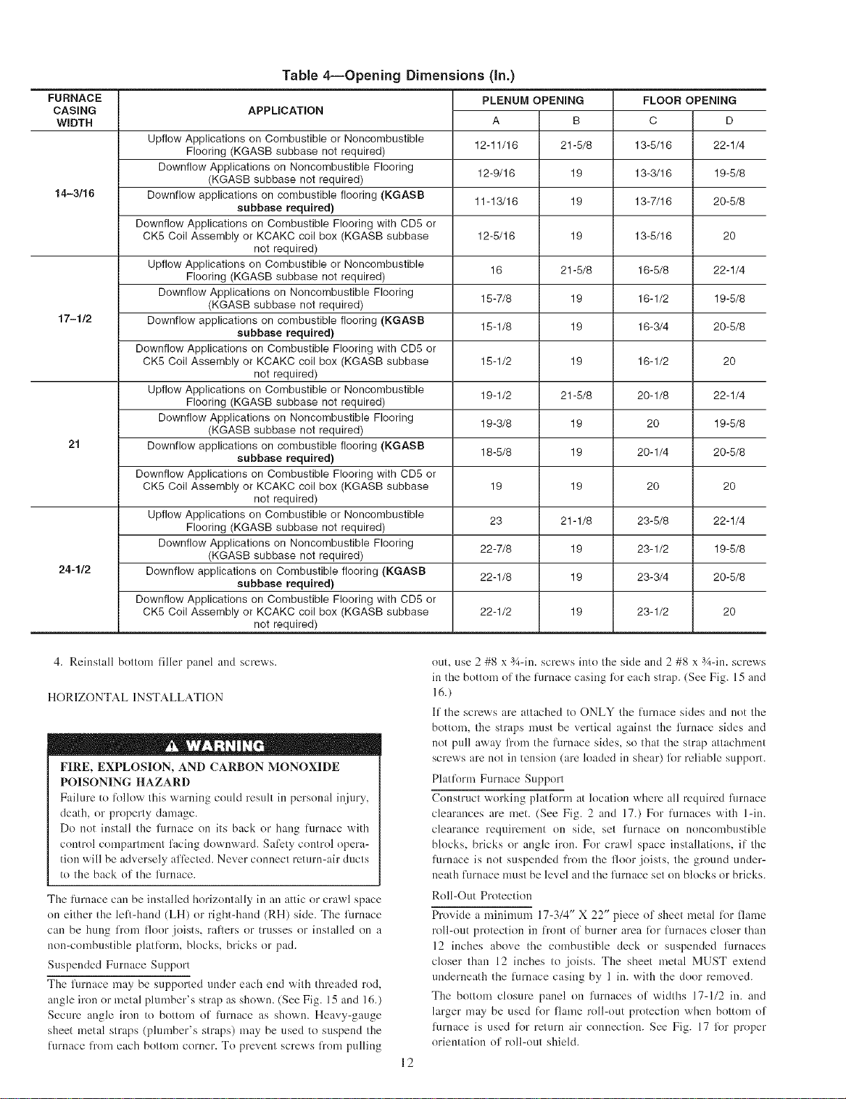
Table 4iOpening Dimensions (In.)
FURNACE
CASING
WIDTH
Upflow Applications on Combustible or Noncombustible
Flooring (KGASB subbase not required) 13-5/16
Downflow Applications on Noncombustible Flooring 13-3/16
14-3/16 Downflow applications on combustible flooring (KGASB 13-7/16
Downflow Applications on Combustible Flooring with CD5 or
CK5 Coil Assembly or KCAKC coil box (KGASB subbase 13-5/16
Upflow Applications on Combustible or Noncombustible 16-5/8
Flooring (KGASB subbase not required)
Downflow Applications on Noncombustible Flooring 16-1/2
17-1/2 Downflow applications on combustible flooring (KGASB 16-3/4
Downflow Applications on Combustible Flooring with CD5 or
CK5 Coil Assembly or KCAKC coil box (KGASB subbase 16-1/2
Upflow Applications on Combustible or Noncombustible 20-1/8
Flooring (KGASB subbase not required)
Downflow Applications on Noncombustible Flooring 20
21 Downflow applications on combustible flooring (KGASB 20-1/4
Downflow Applications on Combustible Flooring with CD5 or
CK5 Coil Assembly or KCAKC coil box (KGASB subbase 20
Upflow Applications on Combustible or Noncombustible 23-5/8
Flooring (KGASB subbase not required)
Downflow Applications on Noncombustible Flooring 23-1/2
24-1/2 Downflow applications on Combustible flooring (KGASB 23-3/4
Downflow Applications on Combustible Flooring with CD5 or
CK5 Coil Assembly or KCAKC coil box (KGASB subbase 23-1/2
APPLICATION
(KGASB subbase not required)
subbase required)
not required)
(KGASB subbase not required)
subbase required)
not required)
(KGASB subbase not required)
subbase required)
not required)
(KGASB subbase not required)
subbase required)
not required)
PLENUM OPENING
A B
12-11/16 21-5/8
12-9/16 19
11-13/16 19
12-5/16 19
16 21-5/8
15-7/8 19
15-1/8 19
15-1/2 19
19-1/2 21-5/8
19-3/8 19
18-5/8 19
19 19
23 21-1/8
22-7/8 19
22-1/8 19
22-1/2 19
FLOOR OPENING
C
22-1/4
19-5/8
20-5/8
22-1/4
19-5/8
20-5/8
22-1/4
19-5/8
20-5/8
22-1/4
19-5/8
20-5/8
D
2O
20
20
20
4. Reinstall bottom filler panel and screws.
HORIZONTAL INSTALLATION
FIRE, EXPLOSION, AND CARBON MONOXIDE
POISONING HAZARD
Failure to lk)llow this warning could result in personal injury,
death, or property damage.
Do not install the furnace on its back or hang lklrnace with
control compamnent facing downward. Sali:ty control opera-
tion will be adversely al_i:cted. Never connect return-air ducts
to the back of' the furnace.
The lurnace can be installed horizontally in an attic or crawl space
on either the leli-hand (LH) or right-hand (RH) side. The furnace
can be hung l)'om floor joists, rafters or trusses or installed on a
non-combustible platlkwm, blocks, bricks or pad.
Suspended Furnace Support
The furnace may be supported under each end with threaded rod,
angle iron or metal plumber's strap as shown. (See Fig. 15 and 16.)
Secure angle iron to bottom of furnace as shown. Heavy-gauge
sheet metal straps (plumber's straps) may be used to suspend the
lhrnace li"om each bottom corner. To prevent screws li"om pulling
out, use 2 #8 x 3A-in. screws into the side and 2 #8 x 3A-in. screws
in the bottom of the lurnace casing lkw each strap. (See Fig. 15 and
16.)
If the screws arc attached to ONLY the lklrnace sides and not the
bottom, the straps nmst be vertical against the furnace sides and
not pull away fi'om the furnace sides, so thai the strap attachment
screws arc not in tension (are loaded in shear) liar reliable support.
Platliwm Furnace Support
Construct working platform at location where all rcqnired furnace
clearances are met. (See Fig. 2 and 17.) For furnaces with l-in.
clearance requirement on side, set furnace on noncombustible
blocks, bricks or angle iron. For crawl space installations_ if the
furnace is not suspended li"om the floor joists, the ground under-
neath lilrnace mnst be level and the furnace set on blocks or bricks.
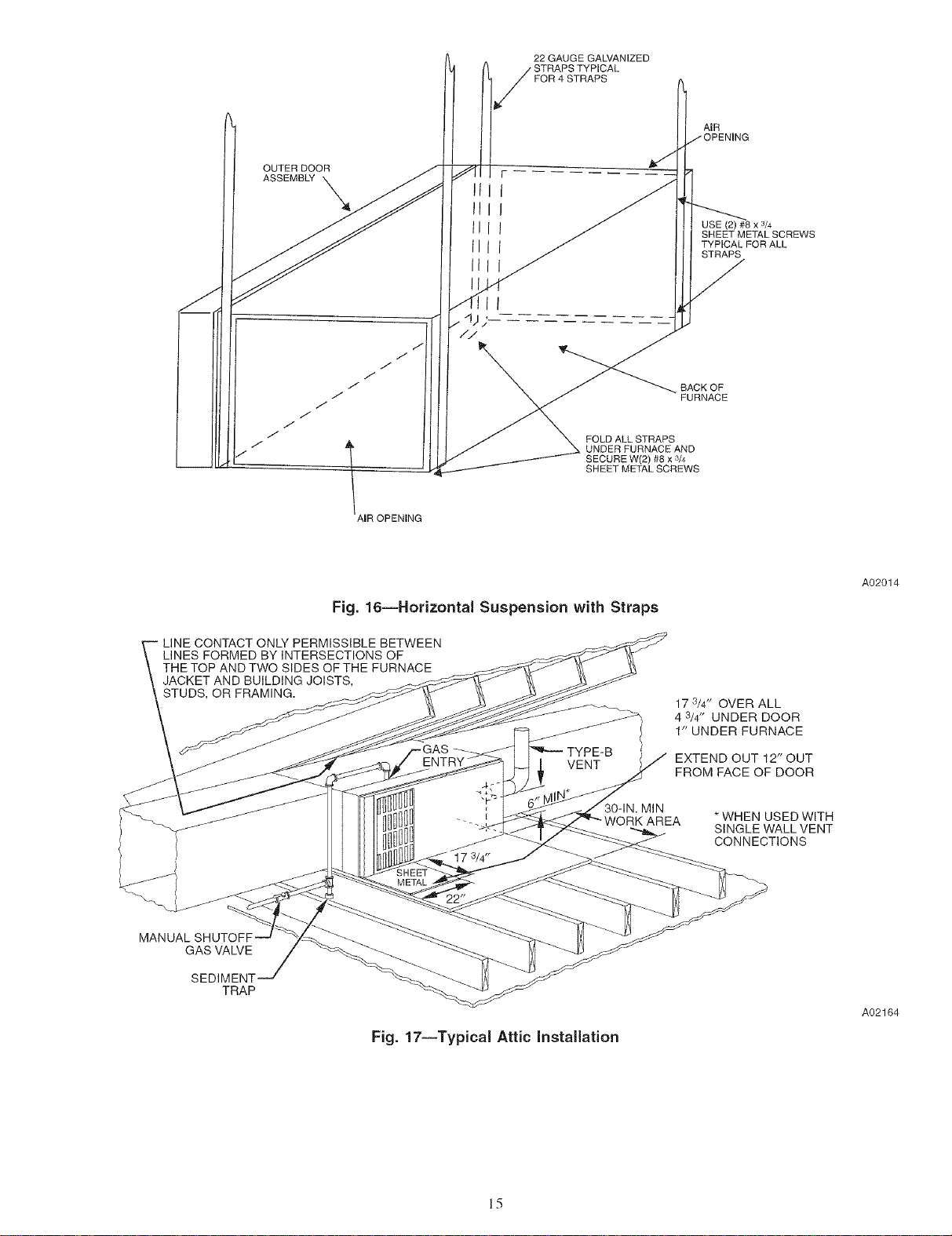
Roll-Out Protection
Provide a ndnimum 174/4" X 22" piece of sheet metal 1()1+flame
roll-out protection in li"ont of burner area lot limmces closer than
12 inches above the combustible deck or suspended furnaces
closer than 12 inches to joists. The sheet metal MUST extend
underneath the limnace casing by 1 in. with the door removed.
The bottom closure panel on furnaces of widths 17-1/2 in. and
larger may be used liw flame roll-out protection when bottom of
furnace is used li_r return air connection. See Fig. 17 liw proper
orientation of roll-out shield.
12
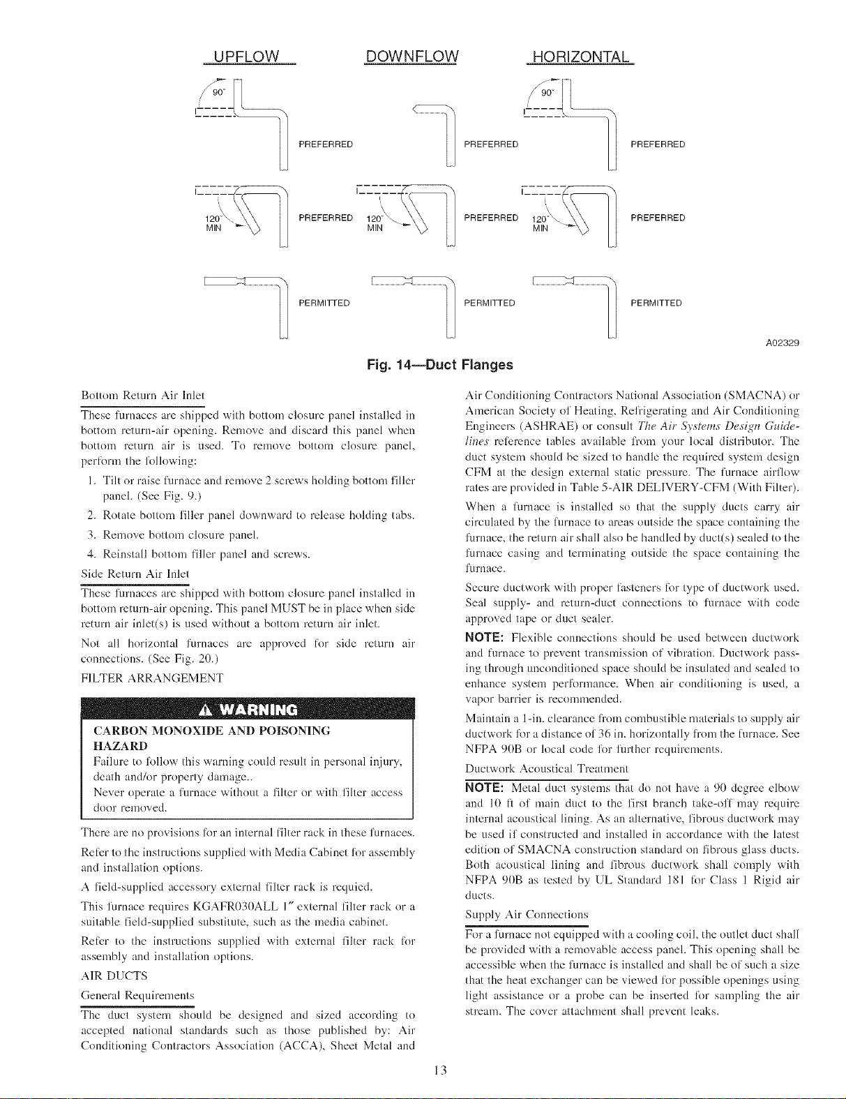
DOW N FLOW HORIZONTAL
PREFERRED
I.
120_
MIN
\
PREFERRED 120_
MIN
PERMITTED PERMITTED PERMITTED
Fig. 14--Duct
Bottom Return Air Inlet
These furnaces are shipped with bottom closure panel installed in
bottom return-air opening, Remove and discard this panel when
bottoul return air is used. To remove bottom closure panel,
perlk_rm the fl_llowing:
1. Tilt or raise lurnace and remove 2 screws holding bottom filler
panel. (See Fig. 9.)
2. Rotate bottom filler panel downward to release holding tabs.
3. Remove bottom closure panel.
4. Reinstall bottom Hller panel and screws.
Side Return Air Inlet
These furnaces are shipped with bottom closure panel installed in
bottom return-air opening. This panel MIIST be in place when side
return air inlet(s) is used without a bottom return air inlet.
Not all horizontal furnaces are approved lk_r side return air
connections. (See Fig. 20.)
FILTER ARRANGEMENT
CARBON MONOXIDE AND POISONING
HAZARD
Failure to lollow this warning could result in personal injury,
death and/or property damage..
Never operate a lurnace without a filter or with filter access
door removed.
There are no provisions fk_ran internal filter rack ilkthese furnaces.
Reli:r to the instructions supplied with Media Cabinet fl_r assembly
and installation options.
A field-supplied accessory external filter rack is requied.
This furnace requires KGAFR030ALL 1" external filter rack or a
suitable field-supplied substitute, such as the media cabinet.
Reli:r to the instructions supplied with external filter rack lor
assembly and installation options.
AIR DUCTS
General Requirements
The duct system should be designed and sized according to
accepted national standards such as those published by: Air
Conditioning Contractors Association (ACCA), Sheet Metal and
PREFERRED PREFERRED
PREFERRED
A02329
Flanges
Air Conditioning Contractors National Association (SMACNA) or
American Society of Heating, Refrigerating and Air Conditioning
Engineers (ASHRAE) or consult The Air Sv,_tum,;De._ign GMd(,-
lines mB:rence tables available l_'om your local distributor, The
duct system should be sized to handle the required system design
CFM at the design external static pressure. The furnace airflow
rates are provided ilkTable 5-A1R DELIVERY-CFM (With Filter).
When a lwnace is installed so that the supply ducts carry air
circulated by the lurnace to areas outside the space containing the
furnace, the return air shall also be handled by duct(s) sealed to the
furnace casing and terminating outside the space containing the
furnace.
Secure ductwork with proper lk_steners lot type of ductwork used,
Seal supply- and retnrn-duct connections to furnace with code
approved tape or duct sealer.
NOTE: Flexible connections should be used between ductwork
and lk]rnace to prevent transmission of vibration. Ductwork pass-
ing through unconditioned space should be insulated and sealed to
enhance system perfl_rmance. When air conditioning is used, a
vapor barrier is recommended.
Maintain a 1-in. clearance fl'om combustible materials to supply air
ductwork fi)r a distance of 36 in. horizontally from the l?lrnace. See
NFPA 90B or local code fl_rfurther requirements.
Ductwork Acoustical Treatment
NOTE: Metal duct systems that do not have a 90 degree elbow
and 10 1i of main duct to the first branch take-off may require
internal acoustical lining. As an alternative, fibrous ductwork may
be used if constructed and installed in accordance with the latest
edition of SMACNA construction standard on fibrous glass ducts.
Both acoustical lining and fibrous ductwork shall comply with
NFPA 90B as tested by UL Standard 181 lor Class 1 Rigid air
ducts.
Supply Air Connections
For a furnace not equipped with a cooling coil, the outlet duct shall
be provided with a removable access panel. This opening shall be
accessible when the limmce is installed and shall be of such a size
that the heat exchanger can be viewed lot possible openings using
light assistance or a probe can be inserted lot sampling the air
stream. The cover attachment shall prevent leaks.
13
V4" THREADED ROD
4 REQ.
J
I
I
I
I
I
UTER DOOR
&SSEMBLY
8" MIN FOR DOOR
REMOVAL
(2) HEX NUTS, (2) WASHERS & (2) LOCK WASHERS
REQ. PER ROD
Fig. 15--Horizontal Unit Suspension
[Jpflow and Horizontal Furnaces
Connect supply-air duct to flanges on furnace supply-air outlet.
Bend flange upward to 90° with wide duct pliers. (See Fig. 14.)
The supply-air duct must be connected to ONLY the furnace
supply-outlet-air duct flanges or air conditioning coil easing (when
used). DO NOT cut main furnace casing side to attach supply air
duct, humidifier, or other accessories. All accessories MUST be
connected to duct external to l_lrnaee main casing.
NOTE: For horizontal applications, the top-most flange may be
bent past 90 degrees to allow the evaporator coil to hang on the
flange temporarily while the remaining attachment and sealing of
the coil are perlormed.
Downflow Furnaces
Connect supply-air duct to supply-air outlet on limmce. Bend
flange inward past 90° with wide duct pliers. (See Fig. 14.) The
supply-air duet nmst be connected to ONLY the limmce supply-
outlet or air conditioning coil casing (when used). When installed
on combustible material, supply-air duct must be connected to
ONLY the accessory subbase KGASB0201ALL or a factory
approved air conditioning coil casing. DO NOT cut main furnace
casing to attach supply side air duct, humidifier, or other accesso-
ries. All accessories MUST be connected to duct external to
lhrnace casing.
¢
SECURE ANGLE
IRON TO BOTTOM
OF FURNACE WITH
3 #8 x 3/4"SCREWS
TYPICAL FOR 2 SUPPORTS
1" SQUARE, 1V4" x 1V4" x %" ANGLE IRON
OR UNI-STRUT MAY BE USED
A05027
Return Air Connections
FIRE HAZARD
Failure to Ii_llow this warning could cause personal injury,
death andkw property damage.
Never connect return-air duets to the back of the furnace.
Follow instructions below.
Downflow Furnaces
The return-air duct nmst be connected to return-air opening
(bottom inlet) as shown in Fig. 19. DO NOT cut into easing sides
(left or right). Side opening is permitted lbr only upflow and most
horizontal furnaces. (See Fig. 19.) Bypass humidifier connections
should be made at ductwork or coil casing sides exterior to
furnace.
Upflow and Horizontal Furnaces
The return-air duct nmst be connected to bottom, sides (left or
right), or a combination of bottom and side(s) of main furnace
casing as shown in Fig. 18 and 20. Bypass humidifier may be
attached into tmused return air side of the furnace casing. (See Fig.
18 and 20.)
Not all horizontal furnaces are approved %r side return air
connections. (See Fig. 20.)
14
OUTER DOOR
ASSEMB_ X
22 GAUGE GALVANIZED
FOR 4 STRAPS
FOLD ALL STRAPS
UNDERFURNACEAND
SECURE W(2)#8x3/4
SHEET METALSCREWS
AIR
USE (2) #8 x 3/4
SHEET METAL SCREWS
TYPICAL FOR ALL
STRAPS
BACK OF
FURNACE
Fig. 16--Horizontal Suspension with Straps
LINE CONTACT ONLY PERMISSIBLE BETWEEN
LINES FORMED BY INTERSECTIONS OF
THE TOP AND TWO SIDES OF THE FURNACE
JACKET AND BUILDING JOISTS,
STUDS, OR FRAMING.
GAS VALVE
SEDIMENT
TRAP
17 3/4" OVER ALL
4 3/4" UNDER DOOR
1" UNDER FURNACE
EXTEND OUT 12" OUT
FROM FACE OF DOOR
MIN
*WHEN USED WITH
SINGLE WALL VENT
CONNECTIONS
A02014
A02164
Fig. 17--Typical Attic Installation
15
 Loading...