

Carrier 58MVC080-F-10114, 58MVC080-F-10120, 58MVC060-F-10114 Installation Guide
Visit www.Carrier.com
®
Turn to the Expertg
Installation Instructions
NOTE: Read the entire instruction manual before starting
the installation.
Please retain these instructions with the furnace after installation
for future reference.
NOTE: This furnace can be installed as a (2-pipe) direct vent
or (1-pipe) non-direct vent condensing gas furnace.
Special Venting Requirements for Installations in Canada
Installation in Canada must conform to the requirements of CSA
B149 code. Vent systems must be composed of pipe, fittings,
cements, and primers listed to ULC $636. The special vent
fittings and accessory concentric vent termination kits and
accessory external drain trap have been certified to ULC $636 for
use with those IPEX PVC vent components which have been
certified to this standard. In Canada, the primer and cement must
be of the same manufacturer as the vent system - IPEX System
636, PVC/CPVC Primer, Purple Violet for Flue Gas Venting and
IPEX System 636(1) TM , PVC Cement for Flue Gas Venting, rated
Class IIA, 65 deg C. must be used with this venting system - do
not mix primers and cements from one manufacturer with a vent
system from a different manufacturer. Follow the manufacturer's
instructions in the use of primer and cement and never use primer
or cement beyond its expiration date.
The safe operation, as defined by ULC $636, of the vent system
is based on following these installation instructions, the vent
system manufacturer's installation instructions, and proper use of
primer and cement. All fire stop and roof flashing used with this
system must be UL listed material. Acceptability under Canadian
standard CSA B149 is dependent upon full compliance with all
installation instructions. Under this standard, it is recommended
that the vent system be checked once a year by qualified service
personnel.
The authority having jurisdiction (gas inspection authority,
municipal building department, fire department, etc) should be
consulted before installation to determine the need to obtain a
permit.
11
ISO 9001:2000
Consignes sp_ciales pour l'installation de ventillation au Canada
L'installation faite au Canada doit se conformer aux exigences du
code CSA B149. Ce syst_me de ventillation doit se composer de
tuyaux, raccords, ciments et appr_ts conformes au ULC $636. La
tuyauterie de ventillation des gaz, ses accessoires, le terminal
concentrique mural ainsi que l'ensemble du drain de condensat
ext_rieur ont _t_ certifies ULCS 636 pour l'application des
composantes IPEX PVC qui sont certifi_es 5. ce standard. Au
Canada l'appr_t et le ciment doivent _tre du m_me manufacturier
que le syst_me de ventillation - IPEX Syst_me 636, Appr_t
PVC/CPVC. Mauve Violette pour conduit en _vacuation des gaz
et IPEX Syst_me 636(1) TM, ciment pour PVC pour conduit en
_vacuation des gaz, _valu_ CLASSE IIA, 65 deg. C. doit _tre
utilis_ avec ce syst_eme d'_vacuation - ne pas m_langer l'appr_t
et le ciment d'un manufacturier avec le syst_me de ventillation
d'un autre manufacturier. Bien suivre les indications du
manufacturier lors de l'utilisation de l'appr_t et du ciment et ne
pas utiliser ceux-ci si la date d'expiration est atteinte.
L'op_ration s_curitaire, tel que d_finit par ULC $636, du syst_me
de ventilation est bass sur les instructions d'installation suivantes,
ainsi que l'usage appropri_ de l'appr_t et ciment. Tout arr_t feu et
solin de toit utilis_s avec ce syst_me doivent _tre des mat_riaux
list,s UL L'acceptation du standard Canadien CSA B419 est
directement reli_ 5. l'installation conforme aux instructions ci-
haut mentionn_es. Le standard Canadien recommande 1'
inspection par un personel qualifi_ et ce, une fois par annie.
Les autorit_es ayant juridiction (inspecteurs de gas, inspecteurs en
bfitiments, d@artement des incendies, etc) devraient _tre
consult_es avant l'installation afin de d_terminer si un permis est
requis.
(1) System 636 is a trademark of IPEX Inc.
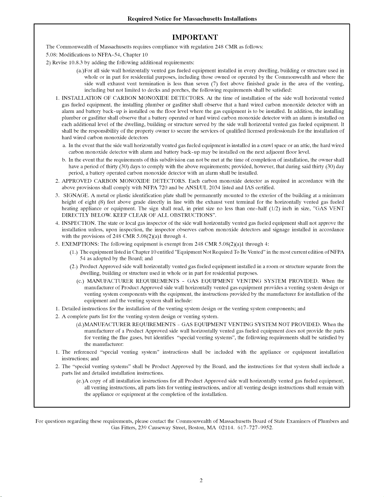
Required Notice for Massachusetts Installations
IMPORTANT
The Commonwealth of Massachusetts requires compliance with regulation 248 CMR as follows:
5.08: Modifications to NFPA-54, Chapter 10
2) Revise 10.8.3 by adding the following additional requirements:
(a.)For all side wall horizontally vented gas fueled equipment installed in every dwelling, building or structure used in
whole or in part for residential purposes, including those owned or operated by the Commonwealth and where the
side wall exhaust vent termination is less than seven (7) feet above finished grade in the area of the venting,
including but not limited to decks and porches, the following requirements shall be satisfied:
1. INSTALLATION OF CARBON MONOXIDE DETECTORS. At the time of installation of the side wall horizontal vented
gas fueled equipment, the installing plumber or gasfitter shall observe that a hard wired carbon monoxide detector with an
alarm and battery back-up is installed on the floor level where the gas equipment is to be installed. In addition, the installing
plumber or gasfitter shall observe that a battery operated or hard wired carbon monoxide detector with an alarm is installed on
each additional level of the dwelling, building or structure served by the side wall horizontal vented gas fueled equipment. It
shall be the responsibility of the property owner to secure the services of qualified licensed professionals for the installation of
hard wired carbon monoxide detectors
a. In the event that the side wall horizontally vented gas fueled equipment is installed in acrawl space or an attic, the hard wired
carbon monoxide detector with alarm and battery back-up may be installed on the next adjacent floor level.
b. In the event that the requirements of this subdivision can not be met at the time of completion of installation, the owner shall
have a period of thirty (30) days to comply with the above requirements; provided, however, that during said thirty (30) day
period, a battery operated carbon monoxide detector with an alarm shall be installed.
2. APPROVED CARBON MONOXIDE DETECTORS. Each carbon monoxide detector as required in accordance with the
above provisions shall comply with NFPA 720 and be ANSI/UL 2034 listed and IAS certified.
3. SIGNAGE. A metal or plastic identification plate shall be permanently mounted to the exterior of the building at a minimum
height of eight (8) feet above grade directly in line with the exhaust vent terminal for the horizontally vented gas fueled
heating appliance or equipment. The sign shall read, in print size no less than one-half (1/2) inch in size, "GAS VENT
DIRECTLY BELOW. KEEP CLEAR OF ALL OBSTRUCTIONS".
4. INSPECTION. The state or local gas inspector of the side wall horizontally vented gas fueled equipment shall not approve the
installation unless, upon inspection, the inspector observes carbon monoxide detectors and signage installed in accordance
with the provisions of 248 CMR 5.08(2)(a)1 through 4.
5. EXEMPTIONS: The following equipment is exempt from 248 CMR 5.08(2)(a)1 through 4:
(1.) The equipment listed in Chapter 10 entitled "Equipment Not Required To Be Vented" in the most current edition of NFPA
54 as adopted by the Board; and
(2.) Product Approved side wall horizontally vented gas fueled equipment installed in a room or structure separate from the
dwelling, building or structure used in whole or in part for residential purposes.
(c.) MANUFACTURER REQUIREMENTS - GAS EQUIPMENT VENTING SYSTEM PROVIDED. When the
manufacturer of Product Approved side wall horizontally vented gas equipment provides a venting system design or
venting system components with the equipment, the instructions provided by the manufacturer for installation of the
equipment and the venting system shall include:
1. Detailed instructions for the installation of the venting system design or the venting system components; and
2. A complete parts list for the venting system design or venting system.
(d.)MANUFACTURER REQUIREMENTS - GAS EQUIPMENT VENTING SYSTEM NOT PROVIDED. When the
manufacturer of a Product Approved side wall horizontally vented gas fueled equipment does not provide the parts
for venting the flue gases, but identifies "special venting systems", the following requirements shall be satisfied by
the manufacturer:
1. The referenced "special venting system" instructions shall be included with the appliance or equipment installation
instructions; and
2. The "special venting systems" shall be Product Approved by the Board, and the instructions for that system shall include a
parts list and detailed installation instructions.
(e.)A copy of all installation instructions for all Product Approved side wall horizontally vented gas fueled equipment,
all venting instructions, all parts lists for venting instructions, and/or all venting design instructions shall remain with
the appliance or equipment at the completion of the installation.
For questions regarding these requirements, please contact the Commonwealth of Massachusetts Board of State Examiners of Plumbers and
Gas Fitters, 239 Causeway Street, Boston, MA 02114. 617-727-9952.
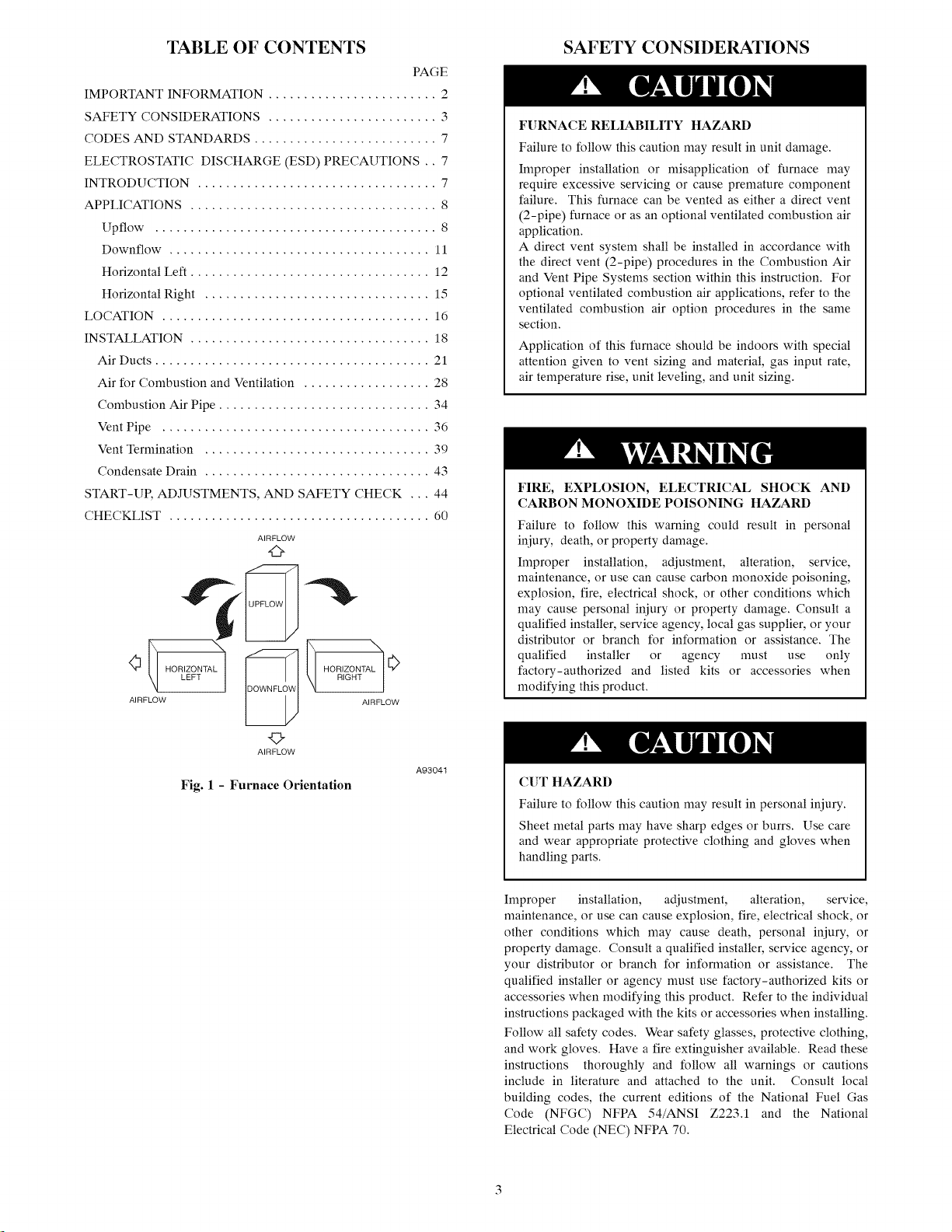
TABLE OF CONTENTS
PAGE
IMPORTANT INFORMATION ........................ 2
SAFETY CONSIDERATIONS ........................ 3
CODES AND STANDARDS .......................... 7
ELECTROSTATIC DISCHARGE (ESD) PRECAUTIONS .. 7
INTRODUCTION .................................. 7
APPLICATIONS ................................... 8
Upflow ........................................ 8
Downflow ..................................... 11
Horizontal Left .................................. 12
Horizontal Right ................................ 15
LOCATION ...................................... 16
INSTALLATION .................................. 18
Air Ducts ....................................... 21
Air for Combustion and Ventilation .................. 28
Combustion Air Pipe .............................. 34
Vent Pipe ...................................... 36
Vent Termination ................................ 39
Condensate Drain ................................ 43
START-UP, ADJUSTMENTS, AND SAFETY CHECK ... 44
CHECKLIST ..................................... 60
AIRFLOW
d>
"i
SAFETY CONSIDERATIONS
FURNACE RELIABILITY HAZARD
Failure to follow this caution may result in unit damage.
Improper installation or misapplication of furnace may
require excessive servicing or cause premature component
failure. This furnace can be vented as either a direct vent
(2-pipe) furnace or as an optional ventilated combustion air
application.
A direct vent system shall be installed in accordance with
the direct vent (2-pipe) procedures in the Combustion Air
and Vent Pipe Systems section within this instruction. For
optional ventilated combustion air applications, refer to the
ventilated combustion air option procedures in the same
section.
Application of this furnace should be indoors with special
attention given to vent sizing and material, gas input rate,
air temperature rise, unit leveling, and unit sizing.
FIRE, EXPLOSION, ELECTRICAL SHOCK AND
CARBON MONOXIDE POISONING HAZARD
Failure to follow this warning could result in personal
iniury, death, or property damage.
Improper installation, adjustment, alteration, service,
maintenance, or use can cause carbon monoxide poisoning,
explosion, fire, electrical shock, or other conditions which
may cause personal iniury or property damage. Consult a
qualified installer, service agency, local gas supplier, or your
distributor or branch for information or assistance. The
qualified installer or agency must use only
factory-authorized and listed kits or accessories when
modifying this product.
©
AIRFLOW
Fig. l - Furnace Orientation
A93041
CUT HAZARD
Failure to follow this caution may result in personal iniury.
Sheet metal parts may have sharp edges or burrs. Use care
and wear appropriate protective clothing and gloves when
handling parts.
Improper installation, adjustment, alteration, service,
maintenance, or use can cause explosion, fire, electrical shock, or
other conditions which may cause death, personal iniury, or
property damage. Consult a qualified installer, service agency, or
your distributor or branch for information or assistance. The
qualified installer or agency must use factory-authorized kits or
accessories when modifying this product. Refer to the individual
instructions packaged with the kits or accessories when installing.
Follow all safety codes. Wear safety glasses, protective clothing,
and work gloves. Have a fire extinguisher available. Read these
instructions thoroughly and follow all warnings or cautions
include in literature and attached to the unit. Consult local
building codes, the current editions of the National Fuel Gas
Code (NFGC) NFPA 54/ANSI Z223.1 and the National
Electrical Code (NEC) NFPA 70.
g
2 IN (51 mm) COMBUSTION
!_lN(13mm)
GAS CONN
2IN
VENTCONN
]_INDIA(13mm)
1
(684 ram)
664 ram)
©
AIRFLOW
A_ (14 ram)
TYP
(829 ram)
(21 ram)
TRAP LOCATION
(DOWNFLOW &
HORIZONTAL LEFT)
;a IN D]A (22ram)
--POWER CONN
ACCESSORY
POWER ENTRY
LOCATION
(ALTERNATE
UPFLOW)
DRAIN TRAP ]
9_s" 17 _16"
TYP (439
(240 ram)
DRAIN LOCATION 11'!6"_ _ 1'16"
(UPFLOW) (17 ram) (17 ram)
NOTES: 1. Minimum return-air openings at furnace, based on metal duct. If flex duct is used,
see flex duct manufactureris recommendations for equivalent diameters.
2. Minimum return-air opening at furnace:
a. For 800 OFM 16-in. (408mm) round or 141A (388 mm)x 12-in. (305 mm) rectangle
b. For !200 CFM 20-in. (508mm) round or 141# (368mm)x 197Mn. (495mm).rectangle
c. For !600 CFM 22-in. (558mm) round or 141# (368mm)x 231/4-in,(591mm) [ectangle
d. For aidlow requirements above 1800 CFM, see Air Delivery table in Product Data
literature for specific use of single side inlets. The use of both side inlets, a
combination of 1 side and the bottom, or the bottom only will ensure adequate
return air openings for airflow requirements above 1800 CFM.
D-- 'l:,r,, "{POUTLET
_NLET
_E_
CONDENSATE DRAIN
(DOWNFLOW &
HORIZONTAL RIGHT) "_
OR ALTERNATE
!_z IN D]A GAS CONN
26 i¢,, (724 mm)
_26 %6" (664 mm)
2614" (667 mm)
22 5i_" (567 mm)_
_19"(463 ram) _ _!3fl6" (21 ram)
I / COMBUSTION AIR OONN b6"|
GAS OONN
......../
1
3O 1< /+-. 2 N _/T,r,l_5 39 7S"
(......... ) f_ _'_"- _/ENTSONN (......... )
1
17......
T_4 E R M O S+_,]r_'T Ry /
SIDE INLET ,
b <1
..........
DRAIN LOCATION / _ 22 11"TYP ------'_'_1 _g_6" (11 ram)
(UPFLOW) (a65 ram)
.............. J --------_OT_;_1r'47----II...... "1 ........ )
FOR HORIZONTAL
HANGING (614 ram)
A05124
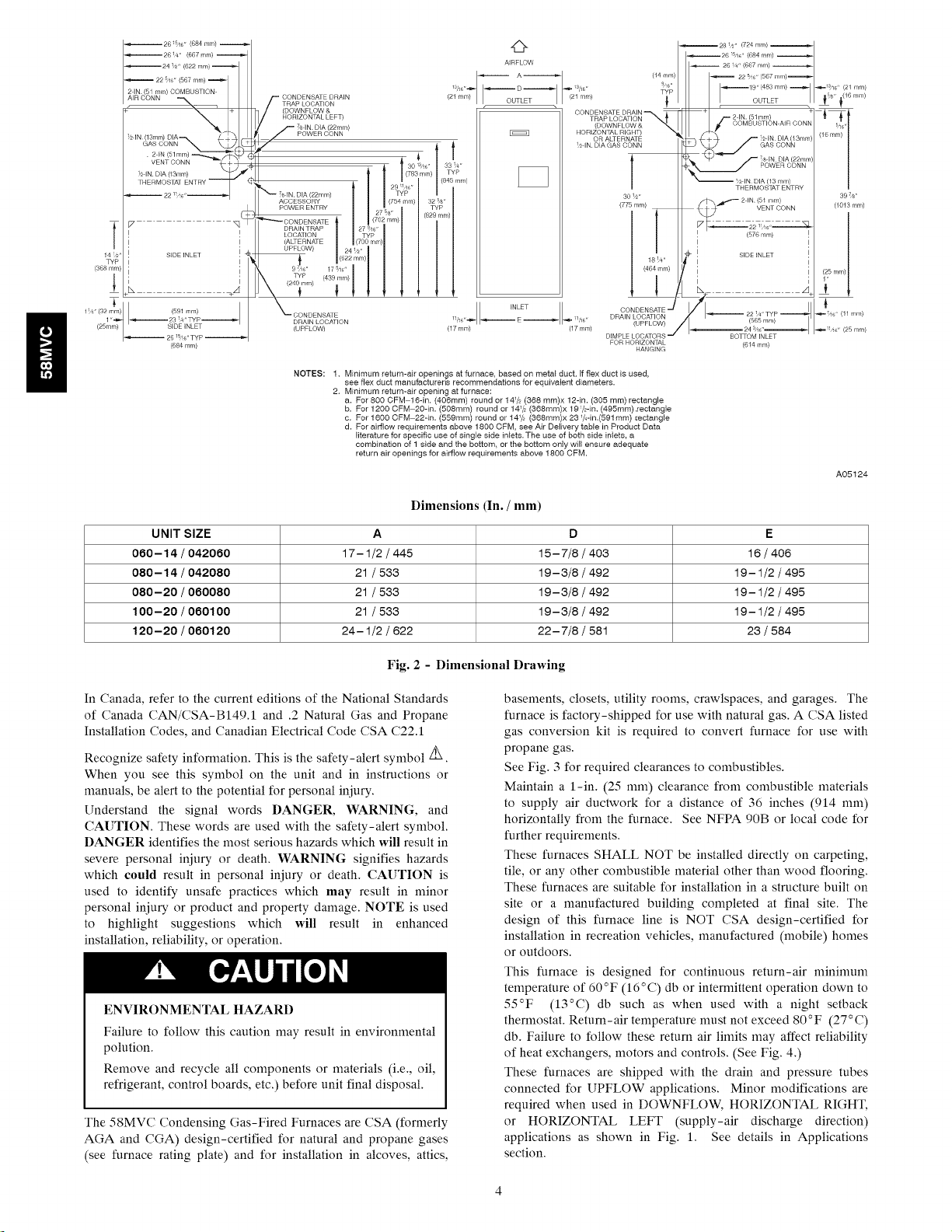
Dimensions (In. / mm)
UNIT SIZE A D E
080-14 / 042080 17-1/2 / 445 15-7/8 / 403 16 / 406
080-14 / 042080 21 / 533 19-3/8 / 492 19-1/2 / 495
080-20 / 080080 21 / 533 19-3/8 / 492 19-1/2 / 495
100-20 / 080100 21 / 533 19-3/8 / 492 19-1/2 / 495
120-20 / 080120 24-1/2 / 822 22-7/8 / 581 23 / 584
Fig. 2 - Dimensional Drawing
In Canada, refer to the current editions of the National Standards
of Canada CAN/CSA-BI49.1 and .2 Natural Gas and Propane
Installation Codes, and Canadian Electrical Code CSA C22.1
Recognize safety information. This is the safety-alert symbol/_.
When you see this symbol on the unit and in instructions or
manuals, be alert to the potential for personal iniury.
Understand the signal words DANGER, WARNING, and
CAUTION. These words are used with the safety-alert symbol.
DANGER identifies the most serious hazards which will result in
severe personal iniury or death. WARNING signifies hazards
which could result in personal iniury or death. CAUTION is
used to identify unsafe practices which may result in nfinor
personal iniury or product and property damage. NOTE is used
to highlight suggestions which will result in enhanced
installation, reliability, or operation.
ENVIRONMENTAL HAZARD
Failure to follow this caution may result in environmental
polution.
Remove and recycle all components or materials (i.e., oil,
refrigerant, control boards, etc.) before unit final disposal.
The 58MVC Condensing Gas-Fired Furnaces are CSA (formerly
AGA and CGA) design-certified for natural and propane gases
(see furnace rating plate) and for installation in alcoves, attics,
basements, closets, utility rooms, crawlspaces, and garages. The
furnace is factory-shipped for use with natural gas. A CSA listed
gas conversion kit is required to convert furnace for use with
propane gas.
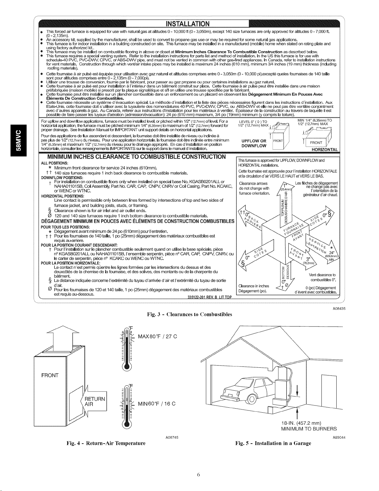
See Fig. 3 for required clearances to combustibles.
Maintain a 1-in. (25 ram) clearance from combustible materials
to supply air ductwork for a distance of 36 inches (914 ram)
horizontally from the furnace. See NFPA 90B or local code for
further requirements.
These furnaces SHALL NOT be installed directly on carpeting,
tile, or any other combustible material other than wood flooring.
These furnaces are suitable for installation in a structure built on
site or a manufactured building completed at final site. The
design of this furnace line is NOT CSA design-certified for
installation in recreation vehicles, manufactured (mobile) homes
or outdoors.
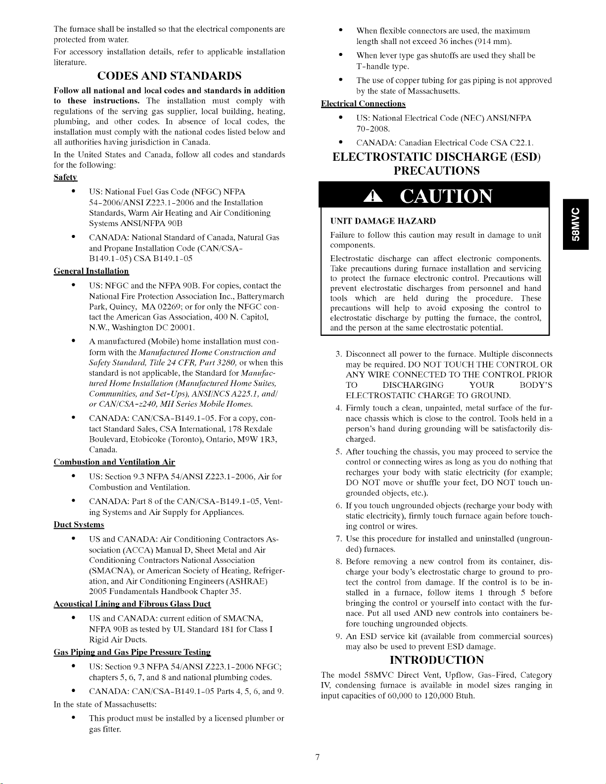
This furnace is designed for continuous return-air minimum
temperature of 60 °F (16 °C) db or internfittent operation down to
55°F (13°C) db such as when used with a night setback
thermostat. Return-air temperature nmst not exceed 80°F (27 °C)
db. Failure to follow these return air linfits may affect reliability
of heat exchangers, motors and controls. (See Fig. 4.)
These furnaces are shipped with the drain and pressure tubes
connected for UPFLOW applications. Minor modifications are
required when used in DOWNFLOW, HORIZONTAL RIGHT,
or HORIZONTAL LEFT (supply-air discharge direction)
applications as shown in Fig. 1. See details in Applications
section.
Install this furnace only in a location and position as specified in
LOCATION and INSTALLATION sections of these instructions.
Combustion products must be discharged outdoors. Connect this
furnace to an approved vent system only, as specified in the
Combustion Air and Vent piping sections of these instructions.
Never test for gas leaks with an open flame. Use a commercially
available soap solution made specifically for detection of leaks to
check all connections as specified in the GAS PIPING section of
these instructions.
Always install the furnace to operate within the furnace's
intended rise range with a duct system which has an external
static pressure within the allowable range as specified in the SET
TEMPERATURE RISE section of these instructions.
When a furnace is installed so that supply ducts carry air
circulated by the furnace to areas outside the space containing the
furnace, the return air shall also be handled by ducts sealed to the
furnace casing and terminating outside the space containing the
furnace.
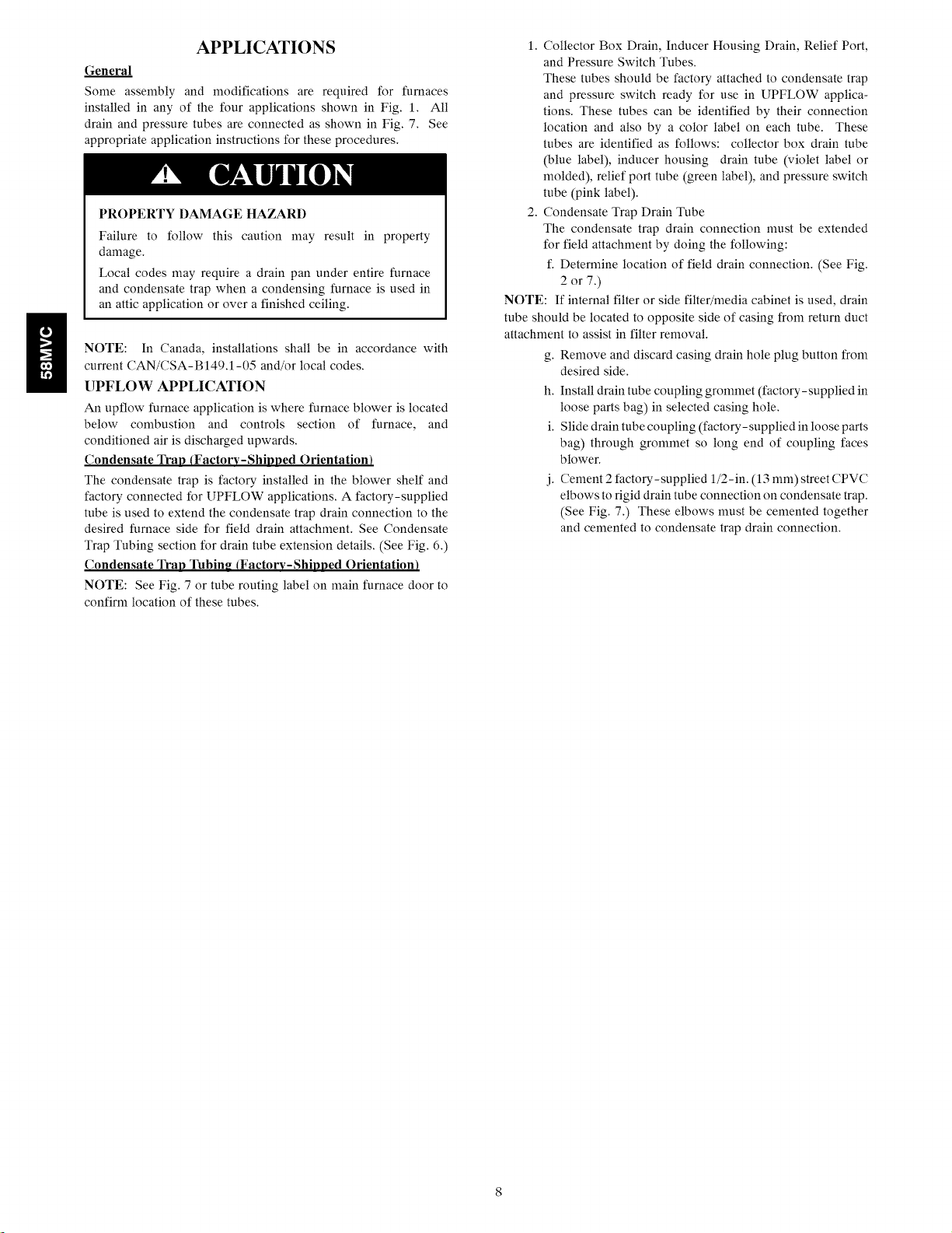
A gas-fired furnace for installation in a residential garage must be
installed as specified in the Hazardous Locations section of these
instructions and Fig. 5.
The furnace may be used for construction heat provided that the
furnace installation and operation complies with the first
CAUTION in the LOCATION section of these instructions.
This gas furnace may be used for construction heat provided that:
• The furnace is permanently installed with all electrical
wiring, piping, air filters, venting and ducting installed
according to these installation instructions. A return air
duct is provided, sealed to the furnace casing, and ter-
minated outside the space containing the furnace. This
prevents a negative pressure condition as created by the
circulating air blower, causing a flame rollout and/or
drawing combustion products into the structure.
• The furnace is controlled by a thermostat. It may not be
"hot wired" to provide heat continuously to the struc-
ture without thermostatic control.
• Clean outside air is provided for combustion. This is to
minimize the corrosive effects of adhesives, sealers and
other construction materials. It also prevents the en-
trainment of drywall dust into combustion air, which
can cause fouling and plugging of furnace components.
• The temperature of the return air to the furnace is main-
tained between 55°F (13°C) and 80°F (27°C), with no
evening setback or shutdown. The use of the furnace
while the structure is under construction is deemed to
be intermittent operation per our installation instruc-
tions.
• The air temperature rise is within the rated rise range on
the furnace rating plate, and the firing rate has been set
to the nameplate value.
• The filters used to clean the circulating air during the
construction process must be either changed or thor-
oughly cleaned prior to occupancy.
• The furnace, ductwork and filters are cleaned as neces-
sary to remove drywall dust and construction debris
from all HVAC system components after construction
is completed.
• After construction is complete, verify furnace operating
conditions including ignition, input rate, temperature
rise and venting, according to the manufacturer's in-
structions.
If this furnace is installed with a direct-vent (combustion air and
flue) system, a factory accessory termination kit must be installed.
In a direct-vent system, all air for combustion is taken directly
from the outside atmosphere and all flue products are discharged
to the outside atmosphere. See furnace and factory accessory
termination kit instructions for proper installation.
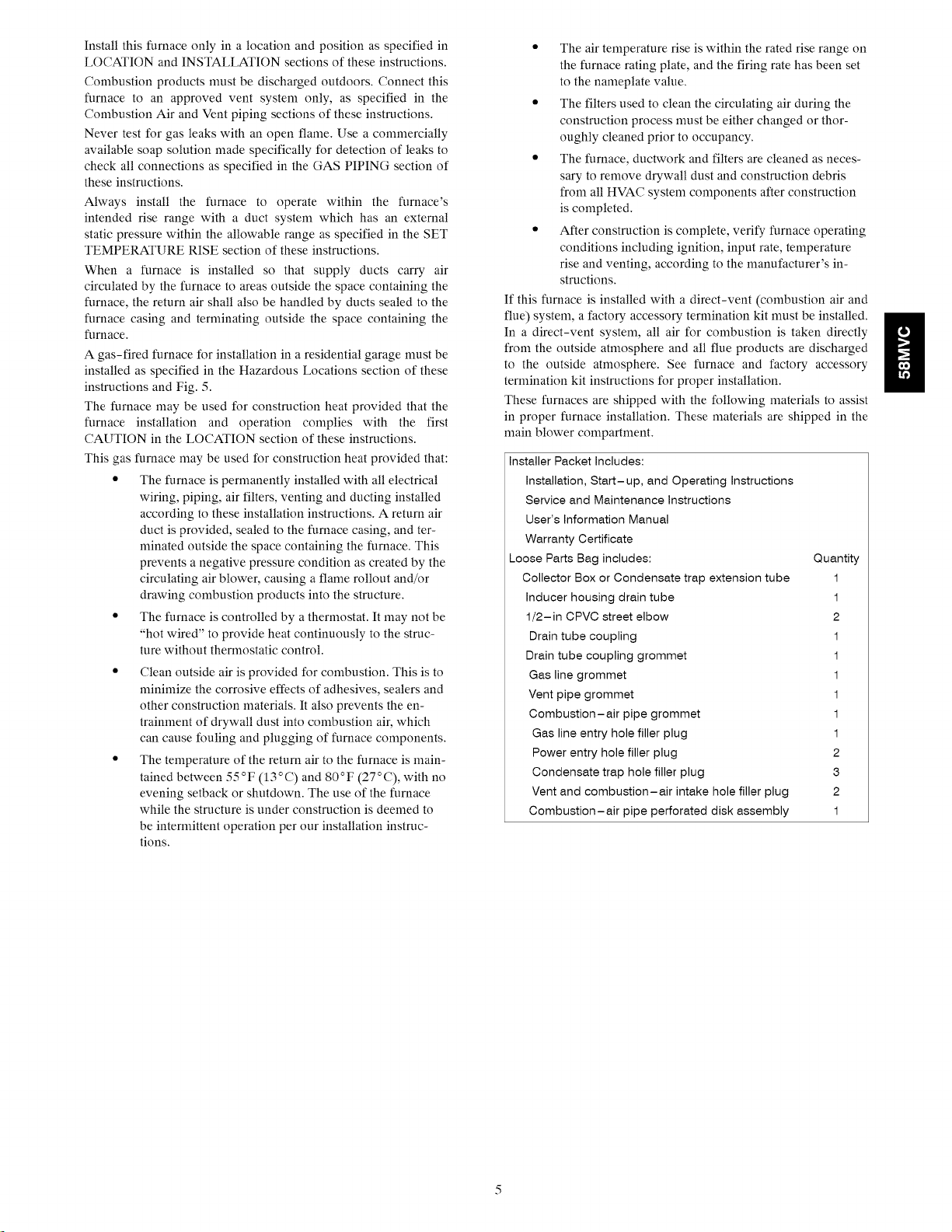
These furnaces are shipped with the following materials to assist
in proper furnace installation. These materials are shipped in the
main blower compartment.
Installer Packet Includes:
Installation, Start-up, and Operating Instructions
Service and Maintenance Instructions
User's Information Manual
Warranty Certificate
Loose Parts Bag includes: Quantity
Collector Box or Condensate trap extension tube 1
Inducer housing drain tube 1
1/2-in CPVC street elbow 2
Drain tube coupling 1
Drain tube coupling grommet 1
Gas line grommet 1
Vent pipe grommet 1
Combustion-air pipe grommet 1
Gas line entry hole filler plug 1
Power entry hole filler plug 2
Condensate trap hole filler plug 3
Vent and combustion-air intake hole filler plug 2
Combustion-air pipe perforated disk assembly 1
g
INSTALLATION
e This forced air fumace is equipped for use with natural gas at altitudes 0 - 10,000 ft (0 - 3,050m), except 140 size furnaces are only approved for altitudes 0 - 7,000 fL
(0 - 2,135m).
• An accessory kit, supplied by the manufacturer, shah be used to convert to propane gas use or may be Pequired for some natural gas applicetions.
• This famace is for indoor installation in a building constructed on site. This furnace may be instated in a manufactured (mobile) home when stated on rating plate and
using factory authorized kit..
• This furnace may be instated on combustible floodng in alsove or closet at Minimum Inches Clearance To Combustible Construction as described below.
e This _mace requires a special venting system. Refer to the installation instructions for parts list and method of installation. In the US this furnace is for use with
schedule=40 PVC, PVC-DWV, CPVC, or AB,S-DWV pipe, and must not be vented in common with other gas-fired appliances. In Canada, refer to installation instructions
for vent materials. Construction through which vent/air intake pipes may be installed is maximum 24 inches (610 ram), minimum 3/4 inches (19 mm) thickness (including
roofing materials).
e Cette foumaise _ air puis6 est 6quip6e pour utilisation avec gaz naturem et altitudes comprises entre 0 - 3,050m (0 - 10,000 pi),except6 queles foumaises de 140 taifle
sont pour altitudes comprises entre 0 - 2,135m (0 - 7,000pi).
® Utiiiser une trousse de conversion, foumie par le fabdcant, pour passer au gaz propane ou pour certaines installations au gaz natureL
e Cette foumaise & air pulse est pour installation a I'intedeur dans un b_timent construit sur place. Cette foumaise a air pulse peut 6tre install6e dans une maison
prCfabdqu6e (maison mobile) si prescrit par la plaque signal6tique et si'l on utilise une trousse specifi6e par le fabrleant.
• C.ette foumaise pout 6tre install6e sur un plancher combustible dans un enfoncement ou un placerd en observant les D6gagernent Minimum En Pouces Avec
EI6ments De Construction Combustibles.
• Cette foumaise n6cessite un syst_me d'6vacuation sp6cial. La m6thode d'instaliation et la iiste des pi_ces n6cessaires figurent dana les instructions d"installation. Aux
Etats-Unis, cette foumaise dolt s'utiliser avec la tuyautede des nomenclatures 40 PVC, PVC-DWV, CPVC, ou ,ABS-DWV et elle ne peut pas _tre ventil6e conjointment
avec d'autres appareils & gaz. Au Canada, referer aux instructions d'installation pour lax matedaux a ventiler. Epaisseur de la construction au travers de laquene il est
possible de faire passer les tuyaux d'aeration (admission/evacuation): 24 po (610 mm) maximum, 3/4 pc (19mm) minimum (y compds la toiture).
For up&3w and downflow applications, furnace must be installed level, or pitched within 1/2" (12.7ram) of level. For a LEVEL 0" ( 0 ) TO _,. MINI 14" (6.35mm) TO
horizonfal application, the furnace must be pitched minimum 1/4" (6.35mm) to maximum of 1/Z' (12.7mm) forward for 1/2" (12.7mm) MAXj ¢_L-_-_ 1/2" (12.7mm)MAX
proper drainage. See Installation Manual for IMPORTANT unit support details on horizontal applications.
Pour des applications de flux ascendant et descendant, la foumaise doit ¢¢e install6e de niveau ou indin6e _ T ............. !
pas plus de 1/2" (12.7mm) du niveau. Pour une application hodzontale, la fOumaise dOlt &'Ire inclle_-_eenli'e minimum UPFLOW OR F_ORON_ )
1/4" (6.35mm) et maximum 1/2" (12.7ram) du niveau pour le drainage appropn& En cas d'installation en position DOWN FLOW
hodzootale, consulter les renseignements mMPORTANTS sur le support dans le manuel d'instaHation. HORIZONTAL
MINIMUMINCHESCLEARANCE TO COMBUSTIBLE CONSTRUCTION
ALL POSiTiONS:
* Minimum front clearance for service 24 inches (610mm).
t 1 140 size furnaces require I inch back clearance to combustible materials.
DOWNFLOW POSITIONS:
t For installation on combustible 11oors only when instated on special base No. KGASB0201ALL or
NAHA01101SB, CoilAssembly, Part No. CAR, CAP, CNPV, CNRV or Coil Casing, Part No. KCAKC,
or WENC or WTNC.
HORIZONTAL POSITIONSi
Line contact is permissible only between lines formed by intersections of top and two sides of
furnace jacket, and building joists, studs, or framing.
§ Clearance shown is for air inlet and air ou_et ends.
O 120 and 140 size furnaces require 1 inch bottom clearance to combustible materials.
DEGAGEMENT MINfl_UIVIEN POUCESAVEC I_LleMENTSDECONSTRUCTION COMBUSTIBLES
POUR TOUS LES POSITIONS:
D@jagement avant minimum de 24 po (610mm ) pour l'entretien.
1- t Pour les foumaises de 140 taifle, 1 pc (25mm) d6gagement des mat6riaux combustibles est
requis au-arriere.
POUR LA POSITION COURANT DESCENDANT:
1 Pour Ilnstaflation sur le plancher combustible seulement quand on utilise la base sp_ciale, piece
n° KGASB0201ALL ou NAHA01101SB, I'ensemble serpentin, pi_:e n ° CAR, CAP, CNPV, CNRV, ou
le carter de serpentin, piece n ° KCAKC ou WENC ou WTNC.
POUR LA POSmON HORIZONTALE:
Le contact n'est permis qQentre les lignes form6es par les intersec_ons du dessus et des
deuxottes de la chemise de la foumaise, et des solives, des montants ou de la charpente du
batiment.
§ La distance indiqu_e conceme I'extr_mit6 du tuyau d'ardv_e d'air et I'extr_mit_ du tuyau de sortie
d'aic
Pour les foumaises de 120 et 140 taifie, 1 pc (25mm) d6gagement des materiaux combustibles
est requis au-dessous.
This furnace is approved for UPFLOW, DOWNFLOW and
HORIZONTAL installations.
Cette foumaise est approuv_e pour I'installation HORIZONTALE
et la circulation d'air VERS LE HAUT et VERS LE BAS.
Clearance arrows Les _hes de degagement
do not change with ne change pas avec
furnace orientation, gen#rateur d'air chaud.
Clearanceininches 0 (pc) D_Jagement
D6gagement(pc). d'_ventaveccombustibles.
I'orientation de la
Vent dearance to
combustibles 0".
FRONT
! MAX80°F/27C
o
_ MIN60°F / 16 C
Fig. 4 - Return-Air Temperature
Fig. 3 - Clearances to Combustibles
A06745
A08435
18-IN. (457.2 mm)
MINIMUM TO BURNERS
A93044
Fig. 5 - Installation in a Garage
Thefurnaceshallbeinstalledsothat the electrical components are
protected from water.
For accessory installation details, refer to applicable installation
literature.
CODES AND STANDARDS
Follow all national and local codes and standards in addition
to these instructions. The installation must comply with
regulations of the serving gas supplier, local building, heating,
plumbing, and other codes. In absence of local codes, the
installation must comply with the national codes listed below and
all authorities having jurisdiction in Canada.
In the United States and Canada, follow all codes and standards
for the following:
US: National Fuel Gas Code (NFGC) NFPA
54-2006/ANSI Z223.1-2006 and the Installation
Standards, Warm Air Heating and Air Conditioning
Systems ANSI/NFPA 90B
CANADA: National Standard of Canada, Natural Gas
and Propane Installation Code (CAN/CSA-
B149.1-05) CSA B149.1-05
General
Combustion and Ventilation Air
Duct Systems
Acoustical Lining and Fibrous Glass Duct
Gas Piping and Gas Pipe Pressure Testing
In the state of Massachusetts:
Installation
• US: NFGC and the NFPA 90B. For copies, contact the
National Fire Protection Association Inc., Batterymarch
Park, Quincy, MA 02269; or for only the NFGC con-
tact the American Gas Association, 400 N. Capitol,
N.W, Washington DC 20001.
• A manufactured (Mobile) home installation nmst con-
form with the Manufactured Home Construction and
Safi, ty Standard, Title 24 CFR, Part 3280, or when this
standard is not applicable, the Standard for Manufac-
tured Home Installation (Manufactured Home Suites,
Communities, and Set-Ups), ANSI/NCS A225.1, and/
or CAN/CSA-z240, MH Series Mobile Homes.
• CANADA: CAN/CSA-B149.1-05. For a copy, con-
tact Standard Sales, CSA International, 178 Rexdale
Boulevard, Etobicoke (Toronto), Ontario, M9W 1R3,
Canada.
• US: Section 9.3 NFPA 54/ANSI Z223.1-2006, Air for
Combustion and Ventilation.
• CANADA: Part 8 of the CAN/CSA-B149.1-05, Vent-
ing Systems and Air Supply for Appliances.
• US and CANADA: Air Conditioning Contractors As-
sociation (ACCA) Manual D, Sheet Metal and Air
Conditioning Contractors National Association
(SMACNA), or American Society of Heating, Refriger-
ation, and Air Conditioning Engineers (ASHRAE)
2005 Fundamentals Handbook Chapter 35.
• US and CANADA: current edition of SMACNA,
NFPA 90B as tested by UL Standard 181 for Class I
Rigid Air Ducts.
• US: Section 9.3 NFPA 54/ANSI Z223A-2006 NFGC;
chapters 5, 6, 7, and 8 and national plumbing codes.
• CANADA: CAN/CSA-BI49.1-05 Parts 4, 5, 6, and 9.
• This product must be installed by a licensed plumber or
gas fitter.
• When flexible connectors are used, the maximum
length shall not exceed 36 inches (914 ram).
• When lever type gas shutoffs are used they shall be
T-handle type.
• The use of copper tubing for gas piping is not approved
by the state of Massachusetts.
Electrical Connections
• US: National Electrical Code (NEC) ANSI/NFPA
70-2008.
• CANADA: Canadian Electrical Code CSA C22.1.
ELECTROSTATIC DISCHARGE (ESD)
PRECAUTIONS
[]NIT DAMAGE HAZARD
Failure to follow this caution may result in damage to unit
components.
Electrostatic discharge can affect electronic components.
Take precautions during furnace installation and servicing
to protect the furnace electronic control. Precautions will
prevent electrostatic discharges from personnel and hand
tools which are held during the procedure. These
precautions will help to avoid exposing the control to
electrostatic discharge by putting the furnace, the control,
and the person at the same electrostatic potential.
3. Disconnect all power to the furnace. Multiple disconnects
may be required. DO NOT TOUCH THE CONTROL OR
ANY WIRE CONNECTED TO THE CONTROL PRIOR
TO DISCHARGING YOUR BODY'S
ELECTROSTATIC CHARGE TO GROUND.
4. Firmly touch a clean, unpainted, metal surface of the fur-
nace chassis which is close to the control. Tools held in a
person's hand during grounding will be satisfactorily dis-
charged.
5. After touching the chassis, you may proceed to service the
control or connecting wires as long as you do nothing that
recharges your body with static electricity (for example;
DO NOT move or shuffle your feet, DO NOT touch un-
grounded objects, etc.).
6. If you touch ungrounded objects (recharge your body with
static electricity), firmly touch furnace again before touch-
ing control or wires.
7. Use this procedure for installed and uninstalled (ungroun-
ded) furnaces.
8. Before removing a new control from its container, dis-
charge your body's electrostatic charge to ground to pro-
tect the control from damage. If the control is to be in-
stalled in a furnace, follow items 1 through 5 before
bringing the control or yourself into contact with the fur-
nace. Put all used AND new controls into containers be-
fore touching ungrounded objects.
9. An ESD service kit (available from commercial sources)
may also be used to prevent ESD damage.
INTRODUCTION
The model 58MVC Direct Vent, Upflow, Gas-Fired, Category
IV, condensing furnace is available in model sizes ranging in
input capacities of 60,000 to 120,000 Btuh.
g
APPLICATIONS
General
Some assembly and modifications are required for furnaces
installed in any of the four applications shown in Fig. 1. All
drain and pressure tubes are connected as shown in Fig. 7. See
appropriate application instructions for these procedures.
PROPERTY DAMAGE HAZARD
Failure to follow this caution may result in property
damage.
Local codes may require a drain pan under entire furnace
and condensate trap when a condensing furnace is used in
an attic application or over a finished ceiling.
current CAN/CSA-B149.1-05 and/or local codes.
NOTE: In Canada, installations shall be in accordance with
UPFLOW APPLICATION
An upflow furnace application is where furnace blower is located
below combustion and controls section of furnace, and
conditioned air is discharged upwards.
Condensate Trap (Factory-Shipped Orientation)
The condensate trap is factory installed in the blower shelf and
factory connected for UPFLOW applications, A factory-supplied
tube is used to extend the condensate trap drain connection to the
desired furnace side for field drain attachment. See Condensate
Trap Tubing section for drain tube extension details, (See Fig. 6.)
Condensate Trap Tubing (Factory-Shipped Orientation)
NOTE: See Fig. 7 or tube routing label on main furnace door to
confirm location of these tubes.
1. Collector Box Drain, Inducer Housing Drain, Relief Port,
and Pressure Switch Tubes.
These tubes should be factory attached to condensate trap
and pressure switch ready for use in UPFLOW applica-
tions. These tubes can be identified by their connection
location and also by a color label on each tube. These
tubes are identified as follows: collector box drain tube
(blue label), inducer housing drain tube (violet label or
molded), relief port tube (green label), and pressure switch
tube (pink label).
2, Condensate Trap Drain Tube
The condensate trap drain connection must be extended
for field attachment by doing the following:
f. Determine location of field drain connection, (See Fig.
2 or 7.)
NOTE: If internal filter or side filter/media cabinet is used, drain
tube should be located to opposite side of casing from return duct
attachment to assist in filter removal.
g. Remove and discard casing drain hole plug button from
desired side.
h. Install drain tube coupling grommet (factory-supplied in
loose parts bag) in selected casing hole.
i. Slide drain tube coupling (factory-supplied in loose parts
bag) through grommet so long end of coupling faces
blower.
j. Cement 2 factory-supplied 1/2-in. (13 mm) street CPVC
elbows to rigid drain tube connection on condensate trap.
(See Fig. 7.) These elbows must be cemented together
and cemented to condensate trap drain connection.
m BLOWER SHELF &-- FURNACE
/_ _TERNATE DRAIN
TUBE LOCATION
CONDENSATE TRAP --
DRAIN TUBE LOCATION
UPFLOW APPLICATIONS
DOOR
\
f_ CONDENSATE
/ TRA;uRNACE -7
j SIDe,,,"
,:_3 ......
_'/ /I 47/8(124mm)
21 J l iie
FIELD,..._
DRAIN
CONN
EXTERNAL UPFLOW APPLICATIONS
SLOT FORSCREW --j
HORIZONTAL /
APPLICATION
(OPTIONAL) /
11/2(88mm)]
261/4 /2
(667mm) (38mm)
SIDE VIEW FRONT VIEW
DOWNFLOW AND ALTERNATE
Uq --- ;
GUIDES -- _1 ,!
(WHEN USED)
FRONT VIEW SIDE VIEW
(57mm)
FURNACE
DOOR
4
(102mm)
FIELD (667mm)
DRAIN
CONN
END VIEW
1/40D
COLLECTOR BOX TO
TRAP RELIEF PORT
1/20D
INDUCER HOUSING
DRAIN CONNECTION
5/80D
COLLECTOR BOX
DRAIN CONNECTION
SCREW HOLE FOR
UPFLOW OR DOWN-
FLOW APPLICATIONS
(OPTIONAL)
1/2 IN. PVC OR CPVC
%2972 /4
(102ram'
HORIZONTAL
APPLICATIONS
FURNACE
SIDE
!
3/4
(19ram)
FRONT Vl EW
4(146mm)
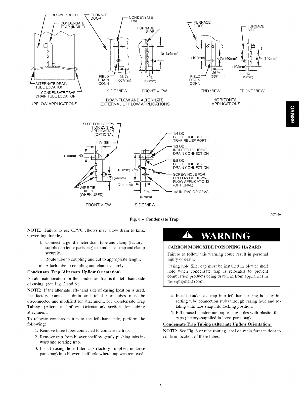
Fig. 6 - Condensate Trap
NOTE: Failure to use CPVC elbows may allow drain to kink,
preventing draining.
k. Connect larger diameter drain tube and clamp (factory-
supplied in loose parts bag) to condensate trap and clamp
securely.
1. Route tube to coupling and cut to appropriate length.
m. Attach tube to coupling and clamp securely.
Condensate Trap (Alternate Upflow Orientation)
An alternate location for the condensate trap is the left-hand side
of casing. (See Fig. 2 and 8.)
NOTE: If the alternate left-hand side of casing location is used,
the factory-connected drain and relief port tubes must be
disconnected and modified for attachment. See Condensate Trap
Tubing (Alternate Upflow Orientation) section for tubing
attachment.
To relocate condensate trap to the left-hand side, perform the
following:
1. Remove three tubes connected to condensate trap.
2. Remove trap from blower shelf by gently pushing tabs in-
ward and rotating trap.
3. Install casing hole filler cap (factory-supplied in loose
parts bag) into blower shelf hole where trap was removed.
A07459
CARBON MONOXIDE POISONING HAZARD
Failure to follow this warning could result in personal
iniury or death.
Casing hole filler cap must be installed in blower shelf
hole when condensate trap is relocated to prevent
combustion products being drawn in from appliances in
the equipment room.
4. Install condensate trap into left-hand casing hole by in-
serting tube connection stubs through casing hole and ro-
tating until tabs snap into locking position.
5. Fill unused condensate trap casing holes with plastic filler
caps (factory-supplied in loose parts bag).
Condensate Trap 3klbing (Alternate Uptlow Orientation)
NOTE: See Fig. 8 or tube routing label on main furnace door to
confirm location of these tubes.
PLUG
COLLECTOR BOX
DRAIN TUBE (BLUE &
WHITE STRIPED)
CAP
COLLECTOR BOX
TUBE (PINK)
INDUCER HOUSING
(MOLDED) DRAIN
TUBE (BEHIND
COLLECTOR BOX
DRAIN TUBE)
COLLECTOR BOX
DRAIN TUBE (BLUE)
COLLECTOR BOX
TUBE (GREEN
ROUTES BEHIND
INDUCER)
CONDENSATE
TRAP
FIELD-INSTALLED
FACTORY-SUPPLIED
DRAIN TUBE
COUPLING (LEFT
DRAIN OPTION)
FIELD-INSTALLED
FACTORY-SUPPLIED
DRAIN TUBE
FIELD-INSTALLED
FIELD-INSTALLED FACTORY-SUPPLIED
FACTORY-SUPPLIED DRAIN TUBE
1/2- IN. CPVC STREET COUPLING (LEFT
ELBOWS (2) FOR DRAIN OPTION)
LEFT DRAIN OPTION
A07274
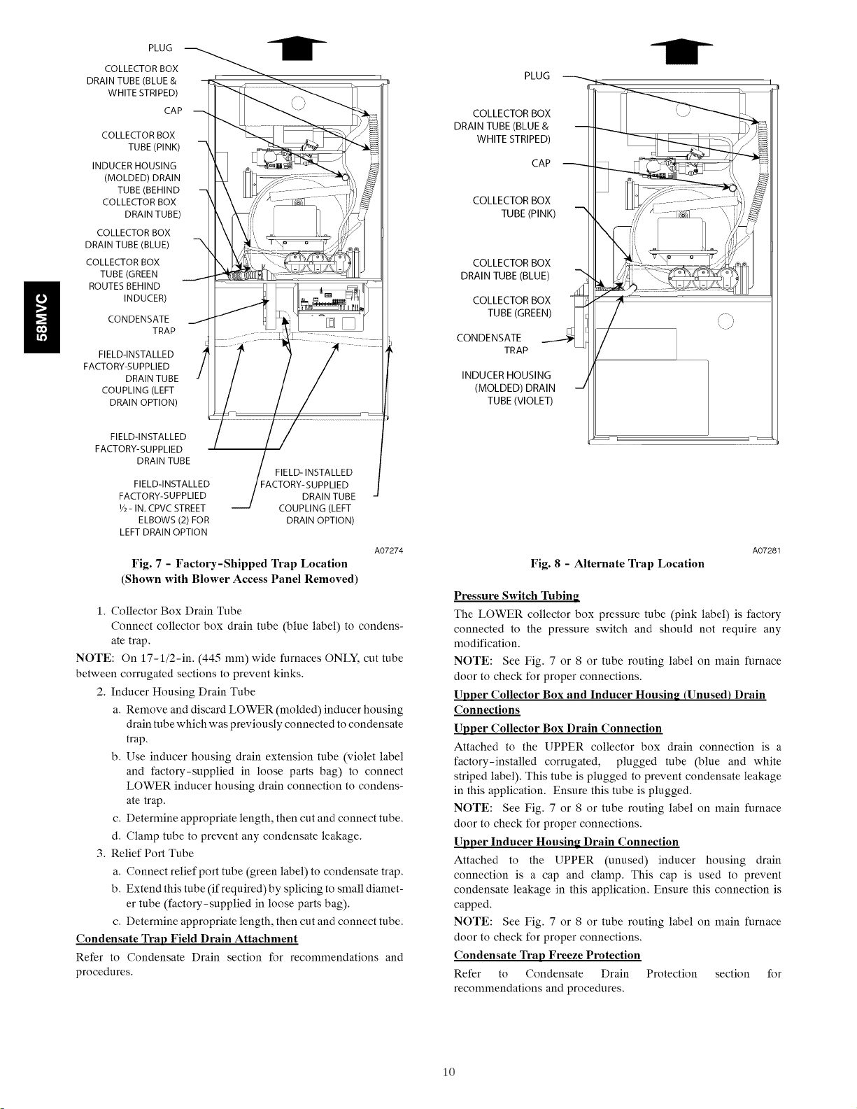
Fig. 7 - Factory-Shipped Trap Location
(Shown with Blower Access Panel Removed)
1. Collector Box Drain Tube
Connect collector box drain tube (blue label) to condens-
ate trap.
NOTE: On 17-1/2-in. (445 ram) wide furnaces ONLY, cut tube
between corrugated sections to prevent kinks.
2. Inducer Housing Drain Tube
a. Remove and discard LOWER (molded) inducer housing
drain tube which was previously connected to condensate
trap.
b. Use inducer housing drain extension tube (violet label
and factory-supplied in loose parts bag) to connect
LOWER inducer housing drain connection to condens-
ate trap.
c. Deternfine appropriate length, then cut and connect tube.
d. Clamp tube to prevent any condensate leakage.
3. Relief Port Tube
a. Connect relief port tube (green label) to condensate trap.
b. Extend this tube (if required) by splicing to small diamet-
er tube (factory-supplied in loose parts bag).
c. Deternfine appropriate length, then cut and connect tube.
Condensate Trap Field Drain Attachment
Refer to Condensate Drain section for recommendations and
procedures.
PLUG
COLLECTOR BOX
DRAIN TUBE (BLUE &
WHITE STRIPED)
CAP
COLLECTOR BOX
TUBE (PINK)
COLLECTOR BOX
DRAIN TUBE (BLUE)
COLLECTOR BOX
TUBE (GREEN) _
CONDENSATE
TRAP
INDUCER HOUSING
(MOLDED) DRAIN
TUBE (VIOLET)
A07281
Fig. 8 - Alternate Trap Location
Pressure Switch Tubing
The LOWER collector box pressure tube (pink label) is factory
connected to the pressure switch and should not require any
modification.
NOTE: See Fig. 7 or 8 or tube routing label on main furnace
door to check for proper connections.
Upper Collector Box and Inducer Housing (Unused) Drain
Connections
Upper Collector Box Drain Connection
Attached to the UPPER collector box drain connection is a
factory-installed corrugated, plugged tube (blue and white
striped label). This tube is plugged to prevent condensate leakage
in this application. Ensure this tube is plugged.
NOTE: See Fig. 7 or 8 or tube routing label on main furnace
door to check for proper connections.
Upper Inducer Housing Drain Connection
Attached to the UPPER (unused) inducer housing drain
connection is a cap and clamp. This cap is used to prevent
condensate leakage in this application. Ensure this connection is
capped.
NOTE: See Fig. 7 or 8 or tube routing label on main furnace
door to check for proper connections.
Condensate Trap Freeze Protection
Refer to Condensate Drain Protection section for
recommendations and procedures.
10
COLLECTORBOX =
DRAINTUBE(BLUE)
PLUG
CAP
COLLECTORBOX
TUBE(GREEN)
COLLECTORBOX
TUBE(PINK)
DRAINTUBE(BLUE&
WHITESTRIPED)
COLLECTORBOX _
COLLECTORBOX
TUBE EXTENS,ON _i i_ _
COLLECTOR BOX
TUBE (GREEN)
CAP
COLLECTOR BOX
DRAIN TUBE (BLUE)
COLLECTOR BOX
S TUBE (PINK)
PLUG
F COLLECTOR BOX
DRAIN TUBE (BLUE &
WHITE STRIPED)
COLLECTOR BOX
TUBE EXTENSION
INDUCER HOUSING
-- (MOLDED) DRAIN
TUBE (VIOLET)
CONDENSATE
TRAP
CONDENSATETRAP __q •
INDUCERHOUSING . _ •
(MOLDED)DRAIN
TUBE(VIOLET)
A07276
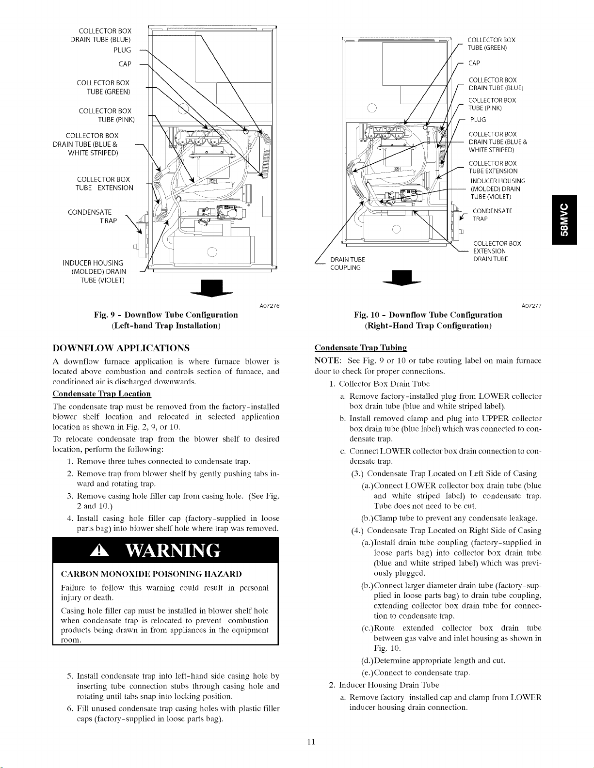
Fig. 9 - Downflow Tube Configuration
(Left-hand Trap Installation)
DOWNFLOW APPLICATIONS
A downflow furnace application is where furnace blower is
located above combustion and controls section of furnace, and
conditioned air is discharged downwards.
Condensate Trap Location
The condensate trap must be removed from the factory-installed
blower shelf location and relocated in selected application
location as shown in Fig. 2, 9, or 10.
To relocate condensate trap from the blower shelf to desired
location, perform the following:
1. Remove three tubes connected to condensate trap.
2. Remove trap from blower shelf by gently pushing tabs in-
ward and rotating trap.
3. Remove casing hole filler cap from casing hole. (See Fig.
2 and 10.)
4. Install casing hole filler cap (factory-supplied in loose
parts bag) into blower shelf hole where trap was removed.
CARBON MONOXIDE POISONING HAZARD
Failure to follow this warning could result in personal
iniury or death.
Casing hole filler cap must be installed in blower shelf hole
when condensate trap is relocated to prevent combustion
products being drawn in from appliances in the equipment
room.
5. Install condensate trap into left-hand side casing hole by
inserting tube connection stubs through casing hole and
rotating until tabs snap into locking position.
6. Fill unused condensate trap casing holes with plastic filler
caps (factory-supplied in loose parts bag).
/
Z DRAIN TUBE
COUPLING
COLLECTOR BOX
EXTENSION
DRAIN TUBE
A07277
Fig. 10 - Downflow Tube Configuration
(Right-Hand Trap Configuration)
Condensate Trap Tubing
NOTE: See Fig. 9 or 10 or tube routing label on main furnace
door to check for proper connections.
1. Collector Box Drain Tube
a. Remove factory-installed plug from LOWER collector
box drain tube (blue and white striped label).
b. Install removed clamp and plug into UPPER collector
box drain tube (blue label) which was connected to con-
densate trap.
c. Connect LOWER collector box drain connection to con-
densate trap.
(3.) Condensate Trap Located on Left Side of Casing
(a.)Connect LOWER collector box drain tube (blue
and white striped label) to condensate trap.
Tube does not need to be cut.
(b.)Clamp tube to prevent any condensate leakage.
(4.) Condensate Trap Located on Right Side of Casing
(a.)Install drain tube coupling (factory-supplied in
loose parts bag) into collector box drain tube
(blue and white striped label) which was previ-
ously plugged.
(b.) Connect larger diameter drain tube (factory-sup-
plied in loose parts bag) to drain tube coupling,
extending collector box drain tube for connec-
tion to condensate trap.
(c.)Route extended collector box drain tube
between gas valve and inlet housing as shown in
Fig. 10.
(d.)Determine appropriate length and cut.
(e.)Connect to condensate trap.
2. Inducer Housing Drain Tube
a. Remove factory-installed cap and clamp from LOWER
inducer housing drain connection.
11
PLUG
AUXILIARY "J" BOX
CONDENSATE
TRAP
CAP
COLLECTOR BOX
TUBE EXTENSION
COLLECTOR BOX
EXTENSION
DRAIN TUBE
DRAIN TUBE
COUPLING
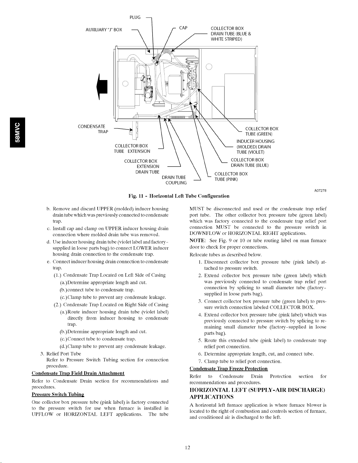
Fig. 11 - Horizontal Left Tube Configuration
COLLECTOR BOX
DRAIN TUBE (BLUE &
WHITE STRIPED)
COLLECTOR BOX
TUBE (GREEN)
INDUCER HOUSING
(MOLDED) DRAIN
TUBE (VIOLET)
COLLECTOR BOX
DRAIN TUBE (BLUE)
COLLECTOR BOX
TUBE (PINK)
A07278
b. Remove and discard UPPER (molded) inducer housing
drain tube which was previously connected to condensate
trap.
c. Install cap and clamp on UPPER inducer housing drain
connection where molded drain tube was removed.
d. Use inducer housing drain tube (violet label and factory-
supplied in loose parts bag) to connect LOWER inducer
housing drain connection to the condensate trap,
e. Connect inducer housing drain connection to condensate
trap.
(1.) Condensate Trap Located on Left Side of Casing
(a.)Determine appropriate length and cut.
(b.)connect tube to condensate trap.
(c.)Clamp tube to prevent any condensate leakage.
(2.) Condensate Trap Located on Right Side of Casing
(a.)Route inducer housing drain tube (violet label)
directly from inducer housing to condensate
trap.
(b.)Determine appropriate length and cut.
(c.)Connect tube to condensate trap.
(d.)Clamp tube to prevent any condensate leakage,
3. Relief Port Tube
Refer to Pressure Switch Tubing section for connection
procedure,
Condensate Trap Field Drain Attachment
Refer to Condensate Drain section for recommendations and
procedures.
Pressure Switch Tubing
One collector box pressure tube (pink label) is factory connected
to the pressure switch for use when furnace is installed in
UPFLOW or HORIZONTAL LEFT applications. The tube
MUST be disconnected and used or the condensate trap relief
port tube, The other collector box pressure tube (green label)
which was factory connected to the condensate trap relief port
connection MUST be connected to the pressure switch in
DOWNFLOW or HORIZONTAL RIGHT applications.
NOTE: See Fig. 9 or 10 or tube routing label on man furnace
door to check for proper connections.
Relocate tubes as described below.
1. Disconnect collector box pressure tube (pink label) at-
tached to pressure switch.
2. Extend collector box pressure tube (green label) which
was previously connected to condensate trap relief port
connection by splicing to small diameter tube (factory-
supplied in loose parts bag).
3. Connect collector box pressure tube (green label) to pres-
sure switch connection labeled COLLECTOR BOX.
4. Extend collector box pressure tube (pink label) which was
previously connected to pressure switch by splicing to re-
maining small diameter tube (factory-supplied in loose
parts bag).
5. Route this extended tube (pink label) to condensate trap
relief port connection.
6. Determine appropriate length, cut, and connect tube.
7. Clamp tube to relief port connection.
Condensate Trap Freeze Protection
Refer to Condensate Drain Protection section for
recommendations and procedures.
HORIZONTAL LEFT (SUPPLY-AIR DISCHARGE)
APPLICATIONS
A horizontal left furnace application is where furnace blower is
located to the right of combustion and controls section of furnace,
and conditioned air is discharged to the left,
12
MAN1
SHUTOFF
GAS VALVE
SEDIMENT
TRAP
COMBUSTION -
INTAKE
(I46 mm)
CONDENSATE
TRAP
30" (762 mm)MIN
)RK AREA
DRAIN
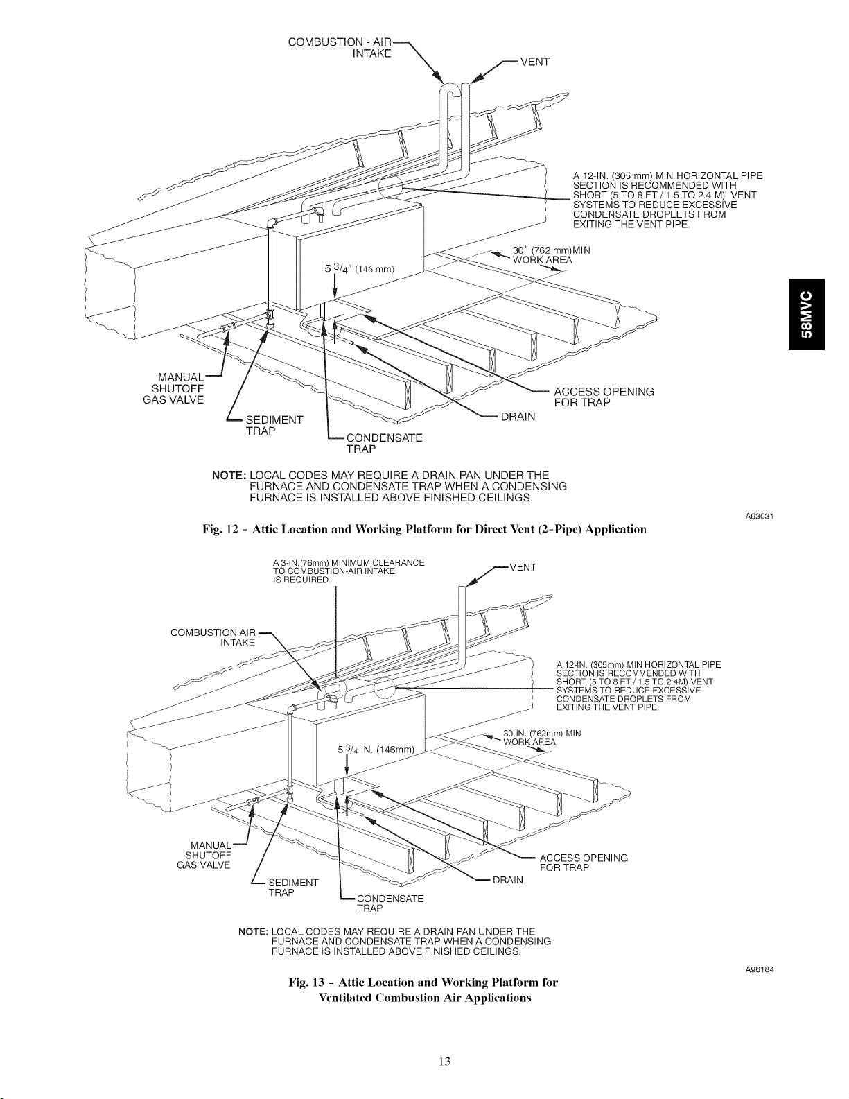
A 12qN. (305 mm) MIN HORIZONTAL PIPE
SECTION IS RECOMMENDED WITH
(5 TO 8 FT/1.5 TO 2.4 M) VENT
SYSTEMS TO REDUCE EXCESSIVE
CONDENSATE DROPLETS FROM
EXITING THE VENT PIPE.
ACCESS OPENING
FOR TRAP
g
NOTE: LOCAL CODES MAY REQUIRE A DRAIN PAN UNDER THE
FURNACE AND CONDENSATE TRAP WHEN A CONDENSING
FURNACE IS INSTALLED ABOVE FINISHED CEILINGS.
Fig. 12 - Attic Location and Working Platform for Direct Vent (2-Pipe) Application
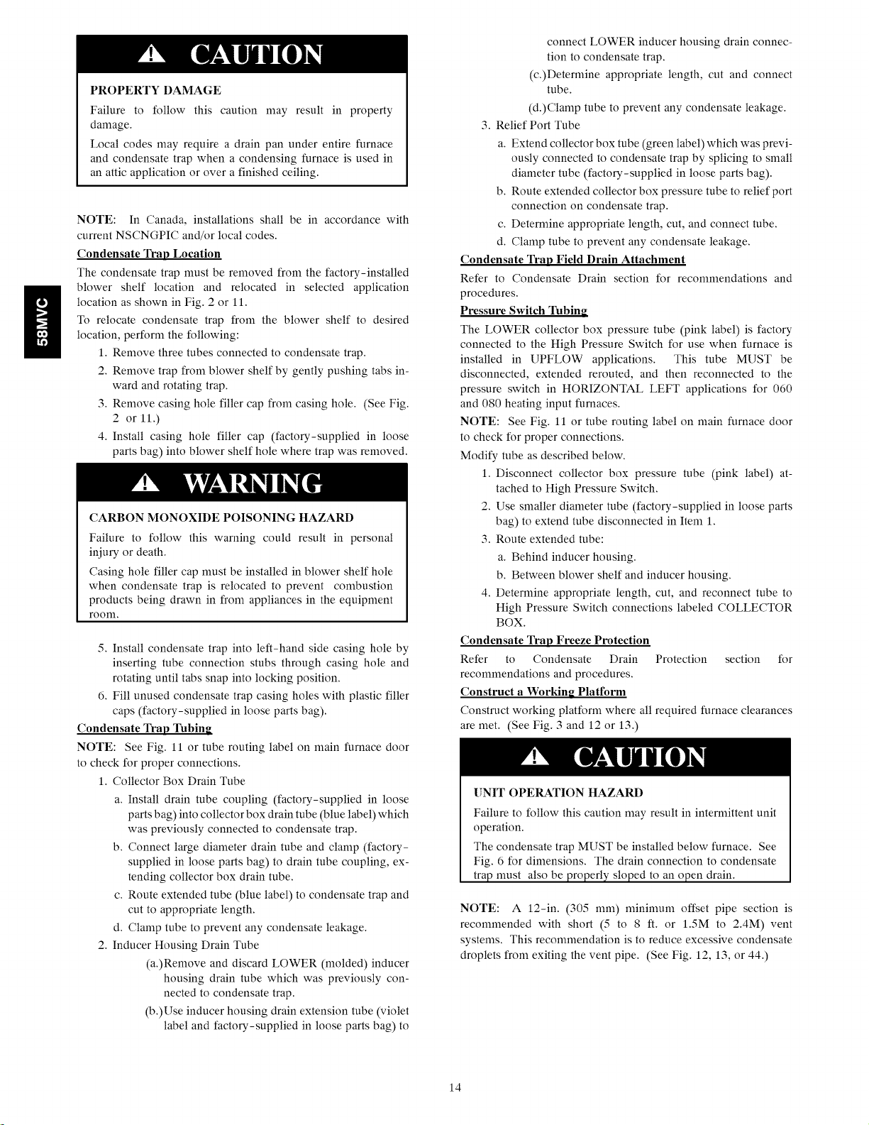
A 3-IN (76mm) MINIMUM CLEARANCE
TO COMBUSTION-AIR INTAKE
IS REQUIRED.
COMBUSTI{
GAS VALVE
MAN[
SHUTOFF
INTAKE
(146mm)
SEDIMENT
TRAP
NOTE: LOCAL CODES MAY REQUIRE A DRAIN PAN UNDER THE
FURNACE AND CONDENSATE TRAP WHEN A CONDENSING
FURNACE IS INSTALLED ABOVE FINISHED CEILINGS.
Fig. 13 - Attic Location and Working Platform for
CONDENSATE
TRAP
Ventilated Combustion Air Applications
30qN. (762mm) MIN
WORK AREA
ACCESS OPENING
DRAIN
FOR TRAP
A 12-IN. (305mm) MIN HORIZONTAL PIPE
SECTION IS RECOMMENDED WITH
SHORT (5 TO 8 FT / 1.5 TQ 2AM) VENT
SYSTEMS TO REDUCE EXCESSIVE
CONDENSATE DROPLETS FROM
EXITING THE VENT PIPE.
A93031
A96184
13
g
PROPERTY DAMAGE
Failure to follow this caution may result in property
damage.
Local codes may require a drain pan under entire furnace
and condensate trap when a condensing furnace is used in
an attic application or over a finished ceiling.
NOTE: In Canada, installations shall be in accordance with
current NSCNGPIC and/or local codes.
Condensate Trap Location
The condensate trapnmst be removed from the factory-installed
blower shelf location and relocated in selected application
location as shown in Fig. 2 or 11.
To relocate condensate trap from the blower shelf to desired
location, perform the following:
1. Remove three tubes connected to condensate trap.
2. Remove trap from blower shelf by gently pushing tabs in-
ward and rotating trap.
3. Remove casing hole filler cap from casing hole. (See Fig.
2 or 11.)
4. Install casing hole filler cap (factory-supplied in loose
parts bag) into blower shelf hole where trap was removed.
CARBON MONOXIDE POISONING HAZARD
Failure to follow this warning could result in personal
injury or death.
Casing hole filler cap must be installed in blower shelf hole
when condensate trap is relocated to prevent combustion
products being drawn in from appliances in the equipment
room.
5, Install condensate trap into left-hand side casing hole by
inserting tube connection stubs through casing hole and
rotating until tabs snap into locking position.
6. Fill unused condensate trap casing holes with plastic filler
caps (factory-supplied in loose parts bag).
Condensate Trap _bing
NOTE: See Fig. 11 or tube routing label on main furnace door
to check for proper connections.
1. Collector Box Drain Tube
a. Install drain tube coupling (factory-supplied in loose
parts bag) into collector box drain tube (blue label) which
was previously connected to condensate trap.
b. Connect large diameter drain tube and clamp (factory-
supplied in loose parts bag) to drain tube coupling, ex-
tending collector box drain tube.
c. Route extended tube (blue label) to condensate trap and
cut to appropriate length.
d. Clamp tube to prevent any condensate leakage.
2. Inducer Housing Drain Tube
(a.)Remove and discard LOWER (molded) inducer
housing drain tube which was previously con-
nected to condensate trap.
(b.)Use inducer housing drain extension tube (violet
label and factory-supplied in loose parts bag) to
connect LOWER inducer housing drain connec-
tion to condensate trap.
(c.)Deternfine appropriate length, cut and connect
tube.
(d.)Clamp tube to prevent any condensate leakage.
3. Relief Port Tube
a. Extend collector box tube (green label) which was previ-
ously connected to condensate trap by splicing to small
diameter tube (factory-supplied in loose parts bag).
b. Route extended collector box pressure tube to relief port
connection on condensate trap.
c. Deternfine appropriate length, cut, and connect tube.
d. Clamp tube to prevent any condensate leakage.
Condensate Trap Field Drain Attachment
Refer to Condensate Drain section for recommendations and
procedures.
Pressure Switch Tubing
The LOWER collector box pressure tube (pink label) is factory
connected to the High Pressure Switch for use when furnace is
installed in UPFLOW applications. This tube MUST be
disconnected, extended rerouted, and then reconnected to the
pressure switch in HORIZONTAL LEFT applications for 060
and 080 heating input furnaces.
NOTE: See Fig. 11 or tube routing label on main furnace door
to check for proper connections.
Modify tube as described below.
1. Disconnect collector box pressure tube (pink label) at-
tached to High Pressure Switch.
2. Use smaller diameter tube (factory-supplied in loose parts
bag) to extend tube disconnected in Item 1.
3. Route extended tube:
a. Behind inducer housing.
b. Between blower shelf and inducer housing.
4. Deternfine appropriate length, cut, and reconnect tube to
High Pressure Switch connections labeled COLLECTOR
BOX.
Condensate Trap Freeze Protection
Refer to Condensate Drain Protection section for
recommendations and procedures.
Construct a Working Platform
Construct working platform where all required furnace clearances
are met, (See Fig. 3 and 12 or 13 0
[]NIT OPERATION HAZARD
Failure to follow this caution may result in internfittent unit
operation.
The condensate trap MUST be installed below furnace. See
Fig. 6 for dimensions. The drain connection to condensate
trap must also be properly sloped to an open drain.
NOTE: A 12-in. (305 ram) nfininmm offset pipe section is
recommended with short (5 to 8 ft. or 1.5M to 2.4M) vent
systems. This recommendation is to reduce excessive condensate
droplets from exiting the vent pipe. (See Fig. 12, 13, or 44.)
14
HORIZONTALRIGHT
(SUPPLY-AIR DISCHARGE) APPLICATIONS
A horizontal right furnace application is where furnace blower is
located to the left of combustion and controls section of furnace,
and conditioned air is discharged to the right.
PROPERTY DAMAGE HAZARD
Failure to follow this caution may result in property
damage.
Local codes may require a drain pan under entire furnace
and condensate trap when a condensing furnace is used in
an attic application or over a finished ceiling.
NOTE: In Canada, installations shall be in accordance with
current NSCNGPIC and/or local codes.
NOTE: The auxiliary junction box (J-box) MUST be relocated
to opposite side of furnace casing. (See Fig. 14.) See Electrical
Connection section for J-box relocation.
Condensate Trap Location
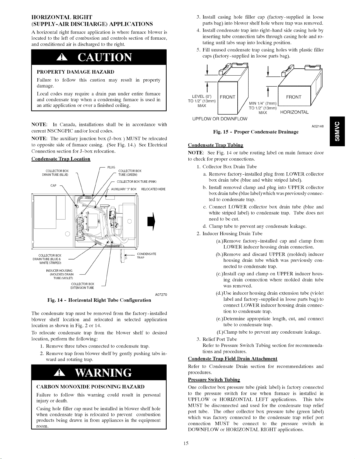
COLLECTOR BOX COLLECTOR BOX
DRAIN TUBE (BLUE) TUBE (GREEN)
CAP
COLLECTOR BOX [J _ CONDENSATE
DRAIN TUBE (BLUE & t]_]3 TRAP
WHITE STRIPED)
INDUCER HOUSING
(MOLDED) DRAIN
TUBE (VIOLET)
COLLECTOR BOX
EXTENSION TUBE
Fig. 14 - Horizontal Right 1hbe Configuration
The condensate trapmust be removed from the factory-installed
blower shelf location and relocated in selected application
location as shown in Fig. 2 or 14.
To relocate condensate trap from the blower shelf to desired
location, perform the following:
1. Remove three tubes connected to condensate trap.
2. Remove trap from blower shelf by gently pushing tabs in-
ward and rotating trap.
CARBON MONOXIDE POISONING HAZARD
Failure to follow this warning could result in personal
injury or death.
Casing hole filler cap must be installed in blower shelf hole
when condensate trap is relocated to prevent combustion
products being drawn in from appliances in the equipment
room.
PLUG
COLLECTOR BOX TUBE (PINK)
AUXILIARY "J" BOX RELOCATED HERE
A07279
3. Install casing hole filler cap (factory-supplied in loose
parts bag) into blower shelf hole where trap was removed.
4. Install condensate trap into right-hand side casing hole by
inserting tube connection tabs through casing hole and ro-
tating until tabs snap into locking position.
5. Fill unused condensate trap casing holes with plastic filler
caps (factory-supplied in loose parts bag).
MIN I/4" (7[l_Lm _
TO 1/2" (13mm)
MAX HORIZONTAL
UPFLOW OR DOWNFLOW
A02146
Fig. 15 - Proper Condensate Drainage
Condensate Trap Tubing
NOTE: See Fig. 14 or tube routing label on main furnace door
to check for proper connections.
1. Collector Box Drain Tube
a. Remove factory-installed plug from LOWER collector
box drain tube (blue and white striped label).
b. Install removed clamp and plug into UPPER collector
box drain tube (blue label) which was previously connec-
ted to condensate trap.
c. Connect LOWER collector box drain tube (blue and
white striped label) to condensate trap. Tube does not
need to be cut.
d. Clamp tube to prevent any condensate leakage.
2. Inducer Housing Drain Tube
(a.)Remove factory-installed cap and clamp from
LOWER inducer housing drain connection.
(b.)Remove and discard UPPER (molded) inducer
housing drain tube which was previously con-
nected to condensate trap.
(c.)Install cap and clamp on UPPER inducer hous-
ing drain connection where molded drain tube
was removed.
(d.)Use inducer housing drain extension tube (violet
label and factory-supplied in loose parts bag) to
connect LOWER inducer housing drain connec-
tion to condensate trap.
(e.)Deternfine appropriate length, cut, and connect
tube to condensate trap.
(f.)Clamp tube to prevent any condensate leakage.
3. Relief Port Tube
Refer to Pressure Switch Tubing section for recommenda-
tions and procedures.
Condenste Trap Field Drain Attachment
Refer to Condensate Drain section for recommendations and
procedures.
Pressure Switch 1hbing
One collector box pressure tube (pink label) is factory connected
to the pressure switch for use when furnace is installed in
UPFLOW or HORIZONTAL LEFT applications. This tube
MUST be disconnected and used for the condensate trap relief
port tube, The other collector box pressure tube (green label)
which was factory connected to the condensate trap relief port
connection MUST be connect to the pressure switch in
DOWNFLOW or HORIZONTAL RIGHT applications,
15
NOTE:SeeFig.14ortuberoutinglabelonmainfurnacedoor
tocheckforproperconnections.
Relocatetubesasdescribedbelow.
1.Disconnectcollectorboxpressuretube(pinklabel)at-
tachedtopressureswitch.
2.Extendcollectorboxpressuretube(greenlabel)which
waspreviouslyconnectedtocondensatetrapreliefport
connectionbysplicingtosmalldiametertube(factory-
suppliedinloosepartsbag.)
3.Connectcollectorboxpressuretube(greenlabel)topres-
sureswitchconnectionlabeledCOLLECTORBOX.
4.Useremainingsmalldiametertube(factory-suppliedin
loosepartsbag)toextendcollectorboxpressuretube
(pinklabel)whichwaspreviouslyconnectedtopressure
switch.
5.Routethisextendedtube(pinklabel)tocondensatetrap
reliefportconnection.
6.DetermineappropriateLength,cut,andconnecttube.
7.Clamptubetoreliefportconnection.
Condensate Trap Freeze Protection
Refer to condensate Drain Protection section for
recommendations and procedures.
Construct a Working Platform
Construct working platform where all required furnace clearances
are met. (See Fig. 3 and 12 or 13.)
UNIT OPERATION HAZARD
Failure to follow this caution may result in intermittent unit
operation.
The condensate trap MUST be installed below furnace. See
Fig. 6 for dimensions. The drain connection to condensate
trap must also be properly sloped to an open drain.
• not be installed directly on any combustible material
other than wood flooring (refer to SAFETY
CONSIDERATIONS).
• be located so combustion-air and vent pipe maximum
lengths are not exceeded. Refer to Table 7.
• be located where available electric power and gas sup-
plies meet specifications on the furnace rating plate.
• be attached to an air distribution system and be located
as close to the center of the distribution system as pos-
sible. Refer to Air Ducts section.
• be provided with ample space for servicing and clean-
ing. Always comply with minimum fire protection
clearances shown on the furnace clearance-to-com-
bustibles label. (See Fig. 3.)
This furnace may be located in a confined space without special
provisions for dilution or ventilation air.
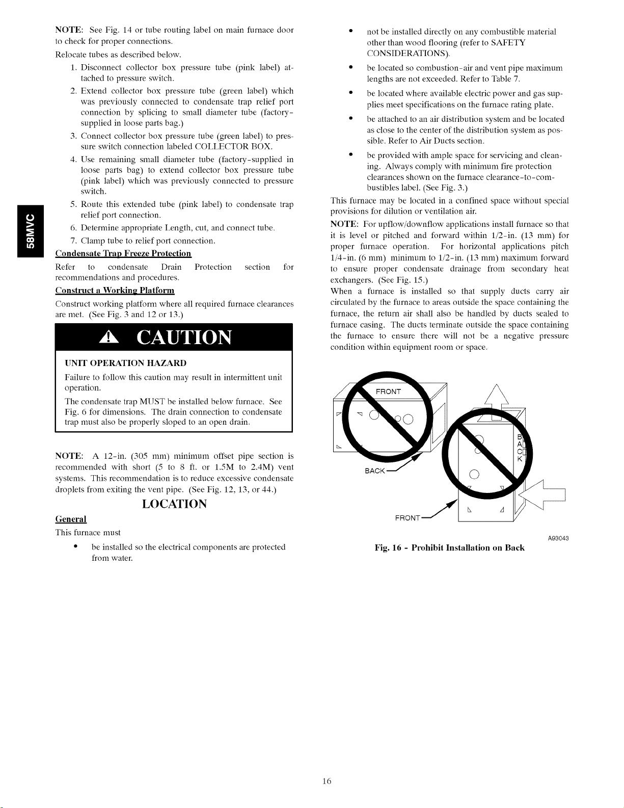
NOTE: For upflow/downflow applications install furnace so that
it is level or pitched and forward within 1/2-in. (13 ram) for
proper furnace operation. For horizontal applications pitch
1/4-in. (6 mm) n_ininmm to 1/2-in. (13 mm) n_axinmm forward
to ensure proper condensate drainage from secondary heat
exchangers. (See Fig. 15.)
When a furnace is installed so that supply ducts carry air
circulated by the furnace to areas outside the space containing the
furnace, the return air shall also be handled by ducts sealed to
furnace casing. The ducts terminate outside the space containing
the furnace to ensure there will not be a negative pressure
condition within equipment room or space.
NOTE: A 12-in. (305 ram) n_ininmm offset pipe section is
recommended with short (5 to 8 ft. or 1.5M to 2.4M) vent
systems. This recommendation is to reduce excessive condensate
droplets from exiting the vent pipe. (See Fig. 12, 13, or 44.)
LOCATION
General
This furnace nmst
• be installed so the electrical components are protected
from water.
BACK
A93043
Fig. 16 - Prohibit Installation on Back
16
[]NIT DAMAGE HAZARD
This gas furnace may be used for construction heat
provided that:
-The furnace is permanently installed with all electrical
wiring, piping, air filters, venting and ducting installed
according to these installation instructions. A return air duct
is provided, sealed to the furnace casing, and ternfinated
outside the space containing the furnace. This prevents a
negative pressure condition as created by the circulating air
blower, causing a flame rollout and/or drawing combustion
products into the structure.
-The furnace is controlled by a thermostat. It may not be
"hot wired" to provide heat continuously to the structure
without thermostatic control.
-Clean outside air is provided for combustion. This is to
nfininfize the corrosive effects of adhesives, sealers and
other construction materials. It also prevents the
entrainment of drywall dust into combustion air, which can
cause fouling and plugging of furnace components.
-The temperature of the return air to the furnace is
maintained between 55°F (13°C) and 80°F (27°C), with
no evening setback or shutdown. The use of the furnace
while the structure is under construction is deemed to be
internfittent operation per our installation instructions.
-The air temperature rise is within the rated rise range on
the furnace rating plate, and the firing rate has been set to
the nameplate value.
-The filters used to clean the circulating air during the
construction process nmst be either changed or thoroughly
cleaned prior to occupancy.
-The furnace, ductwork and filters are cleaned as necessary
to remove drywall dust and construction debris from all
HVAC system components after construction is completed.
-After construction is complete, verify furnace operating
conditions including ignition, input rate, temperature rise
and venting, according to the manufacturer's instructions.
FIRE OR DEATH HAZARD
Failure to follow this warning could result in property
damage, personal injury, or death.
Do not install furnace on its back. (See Fig. 16.) Safety
control operation will be adversely affected. Never connect
return-air ducts to back of furnace.
The furnace and its return air system shall be designed and
installed so that negative pressure created by the air circulating
fan cannot affect another appliance's combustion air supply or act
to nfix products of combustion with circulating air, and that the
air circulating fan of the furnace, if installed in an enclosure
communicating with another fuel-burning appliance not of the
direct-vent type, shall be operable only when any door or panel
covering an opening in the furnace fan compartment or in a return
air plenum on ducts is in the closed position.
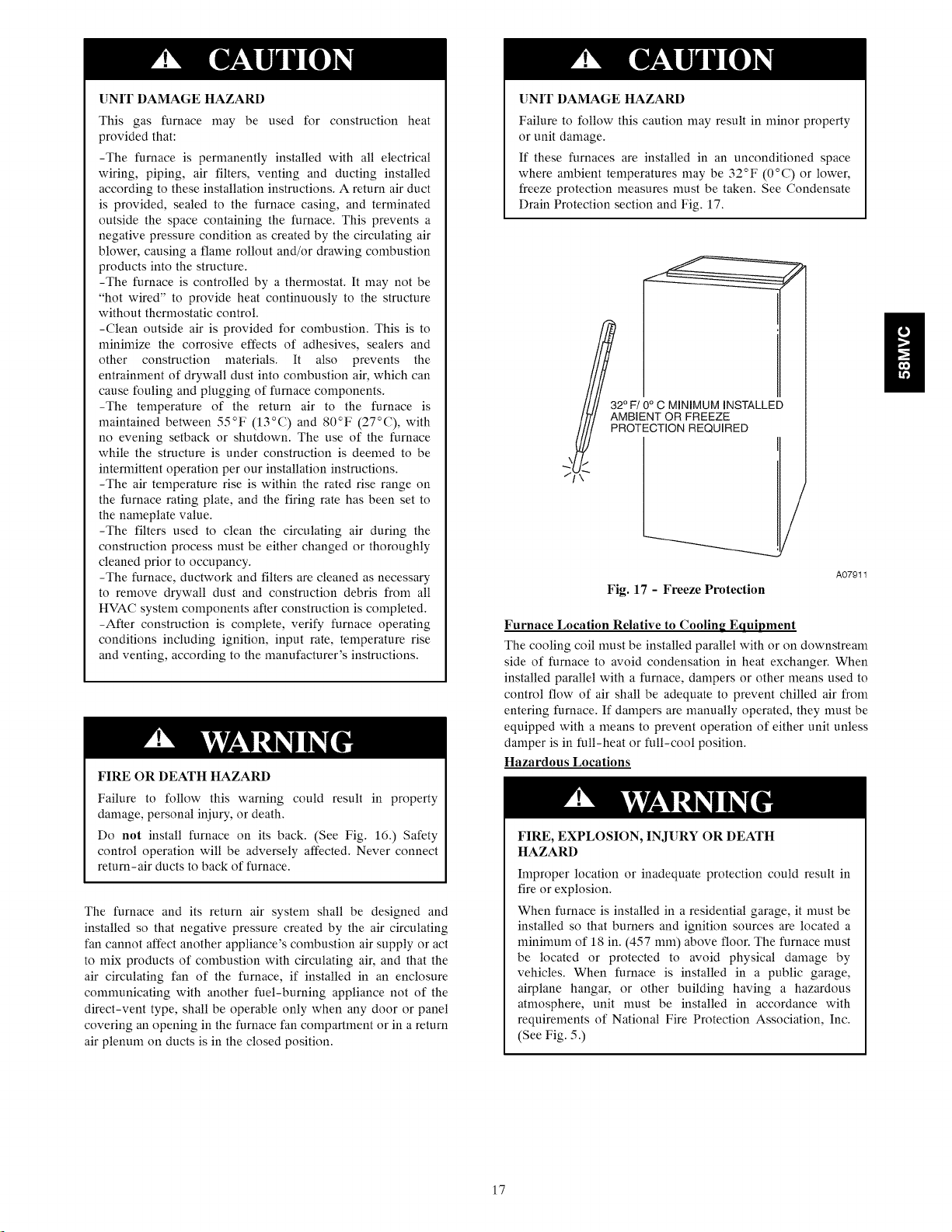
UNIT DAMAGE HAZARD
Failure to follow this caution may result in nfinor property
or unit damage.
If these furnaces are installed in an unconditioned space
where ambient temperatures may be 32°F (0°C) or lower,
freeze protection measures must be taken. See Condensate
Drain Protection section and Fig. 17.
g
_3/ff/ 2MFfONCg4NFIMgMZI#STALLED
_ PROTECTION REQUIRED
/
A07911
Fig. 17 - Freeze Protection
Furnace Location Relative to Cooling Equipment
The cooling coil must be installed parallel with or on downstream
side of furnace to avoid condensation in heat exchanger. When
installed parallel with a furnace, dampers or other means used to
control flow of air shall be adequate to prevent chilled air from
entering furnace. If dampers are manually operated, they nmst be
equipped with a means to prevent operation of either unit unless
damper is in full-heat or full-cool position.
Hazardous Locations
FIRE, EXPLOSION, INJURY OR DEATH
HAZARD
Improper location or inadequate protection could result in
fire or explosion,
When furnace is installed in a residential garage, it nmst be
installed so that burners and ignition sources are located a
nfininmm of 18 in. (457 ram) above floor. The furnace nmst
be located or protected to avoid physical damage by
vehicles. When furnace is installed in a public garage,
airplane hangar, or other building having a hazardous
atmosphere, unit must be installed in accordance with
requirements of National Fire Protection Association, Inc.
(See Fig. 5.)
17
(8ram)
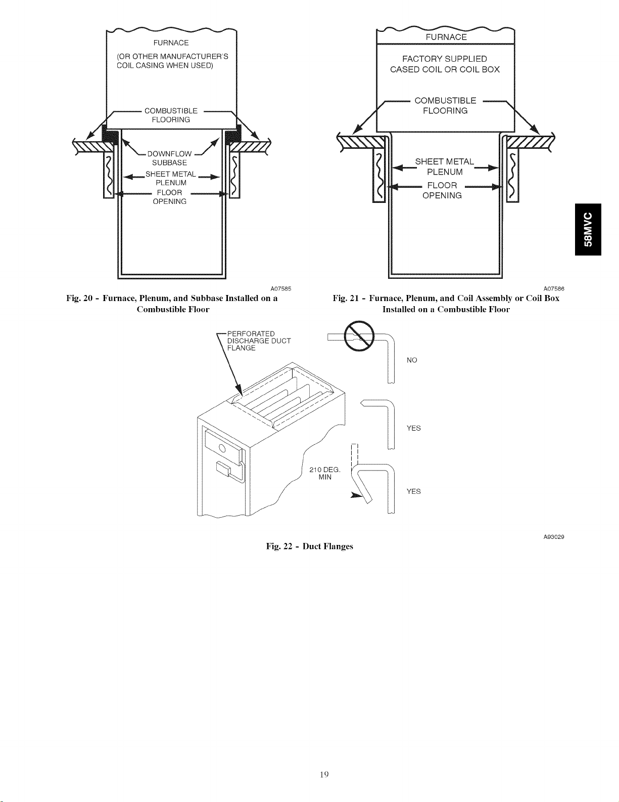
and forth until it breaks off. Be careful of sharp edges. (See Fig.
22.)
g
1 3/4
(44ram)
1 3/4"
(44ram)
(8ram)
5/16"
(8mm)
(44mm) 1 3/4"
(44mm) 1
A89014
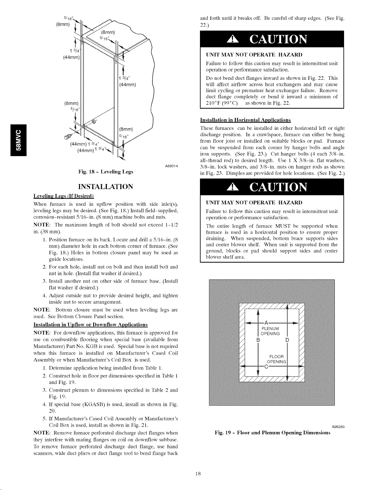
Fig. 18 - Leveling Legs
INSTALLATION
Levelin_ Le_s (If Desired)
When furnace is used in upflow position with side inlet(s),
leveling legs may be desired. (See Fig. 18.) Install field-supplied,
corrosion-resistant 5/16-in. (8 ram) machine bolts and nuts.
NOTE: The maximum length of bolt should not exceed 1-1/2
in. (38 mm).
1. Position furnace on its back. Locate and drill a 5/16-in. (8
ram) diameter hole in each bottom corner of furnace. (See
Fig. 18.) Holes in bottom closure panel may be used as
guide locations.
2. For each hole, install nut on bolt and then install bolt and
nut in hole. (Install flat washer if desired.)
3. Install another nut on other side of furnace base. (Install
flat washer if desired.)
4. Adjust outside nut to provide desired height, and tighten
inside nut to secure arrangement.
NOTE: Bottom closure nmst be used when leveling legs are
used. See Bottom Closure Panel section.
Installation in Upflow or Downflow Applications
NOTE: For downflow applications, this furnace is approved for
use on combustible flooring when special base (available from
Manufacturer) Part No. KGB is used. Special base is not required
when this furnace is installed on Manufacturer's Cased Coil
Assembly or when Manufacturer's Coil Box is used.
1. Determine application being installed from Table 1.
2. Construct hole in floor per dimensions specified in Table 1
and Fig. 19.
3. Construct plenum to dimensions specified in Table 2 and
Fig. 19.
4. If special base (KGASB) is used, install as shown in Fig.
20.
5. If Manufacturer's Cased Coil Assembly or Manufacturer's
Coil Box is used, install as shown in Fig. 21.
NOTE: Remove furnace perforated discharge duct flanges when
they interfere with mating flanges on coil on downflow subbase.
To remove furnace perforated discharge duct flange, use hand
scanners, wide duct pliers or duct flange tool to bend flange back
[]NIT MAY NOT OPERATE HAZARD
Failure to follow this caution may result in intermittent unit
operation or performance satisfaction.
Do not bend duct flanges inward as shown in Fig. 22. This
will affect airflow across heat exchangers and may cause
limit cycling or premature heat exchanger failure. Remove
duct flange completely or bend it inward a minimum of
210°F (99°C) as shown in Fig. 22.
Installation in Horizontal Applications
These furnaces can be installed in either horizontal left or right
discharge position. In a crawlspace, furnace can either be hung
from floor joist or installed on suitable blocks or pad. Furnace
can be suspended from each corner by hanger bolts and angle
iron supports. (See Fig. 23.) Cut hanger bolts (4 each 3/8-in.
all-thread rod) to desired length. Use 1 X 3/8-in. flat washers,
3/8-in. lock washers, and 3/8-in. nuts on hanger rods as shown
in Fig. 23. Dimples are provided for hole locations. (See Fig. 2.)
[]NIT MAY NOT OPERATE HAZARD
Failure to follow this caution may result in intermittent unit
operation or performance satisfaction.
The entire length of furnace MUST be supported when
furnace is used in a horizontal position to ensure proper
draining. When suspended, bottom brace supports sides
and center blower shelf. When unit is supported from the
ground, blocks or pad should support sides and center
blower shelf area.
A96283
Fig. 19 - Floor and Plenum Opening Dimensions
18
FURNACE
(OR OTHER MANUFACTURER'S
COIL CASING WHEN USED)
FURNACE
FACTORY SUPPLIED
CASED COIL OR COIL BOX
COMBUSTIBLE
FLOORING
SUBBASE
SHEET METAL
PLENUM
FLOOR
OPENING
Fig. 20 - Furnace, Plenum, and Subbase Installed on a
Combustible Floor
DISCHARGE DUCT
FLANGE
A07585
/_ COMBUSTIBLE
FLOORING
SHEET METAL
PLENUM
FLOOR -_
OPENING
A07586
Fig. 21 - Furnace, Plenum, and Coil Assembly or Coil Box
Installed on a Combustible Floor
NO
210 DEG.
MIN
Fig. 22 - Duct Flanges
YES
YES
A93029
19
 Loading...