

Page 1

HEATING & COOLING
Single-Package Rooftop Heating/Cooling Units
User’s Information Manual
NOTE TO INSTALLER
This manual should be left with the equipment owner.
FOR YOUR SAFETY
Do not store or use gasoline or other
flammable vapors and liquids in the vicinity
of this or any other appiiance.
A WARNING
Improper installation, adjustment, alteration, ser
vice or maintenance can cause injury or prop
erty damage. Refer to this manual. For assis
tance or additional information consult a qualified
installer, service agency or the gas supplier.
FOR YOUR SAFETY
WHAT TO DO IF YOU SMELL GAS
• Do not try to light any appliance.
• Do not touch any electrical switch; do not
use any phone in your building.
• Immediately call your gas supplier from a
neighbor’s phone. Follow the gas suppli
er’s instructions.
• If you cannot reach your gas supplier, call
the fire department.
A WARNING
Before performing recommended maintenance, be sure
main power switch to unit is turned off. Electrical shock
could cause personal injury.
Your rooftop combination heating/cooling unit is equipped
with an automatic direct spark ignition and induced draft
combustion blower.
A WARNING
Do not attempt to light by hand; personal injury may
result.
TO LIGHT UNIT
A DANGER
1. Do not turn off the electrical power to unit without
first turning off the gas supply.
2. Before attempting to start the gas heating section,
familiarize yourself with all the procedures that must
be followed.
If you do not follow these instructions exactly, a fire
or explosion may result, causing property damage, in
jury or loss of life.
48DJD,LJD005-014
48DJE,LJE004-012
INTAKE
LOUVERS
Fig. 1 — Gas Valve Location
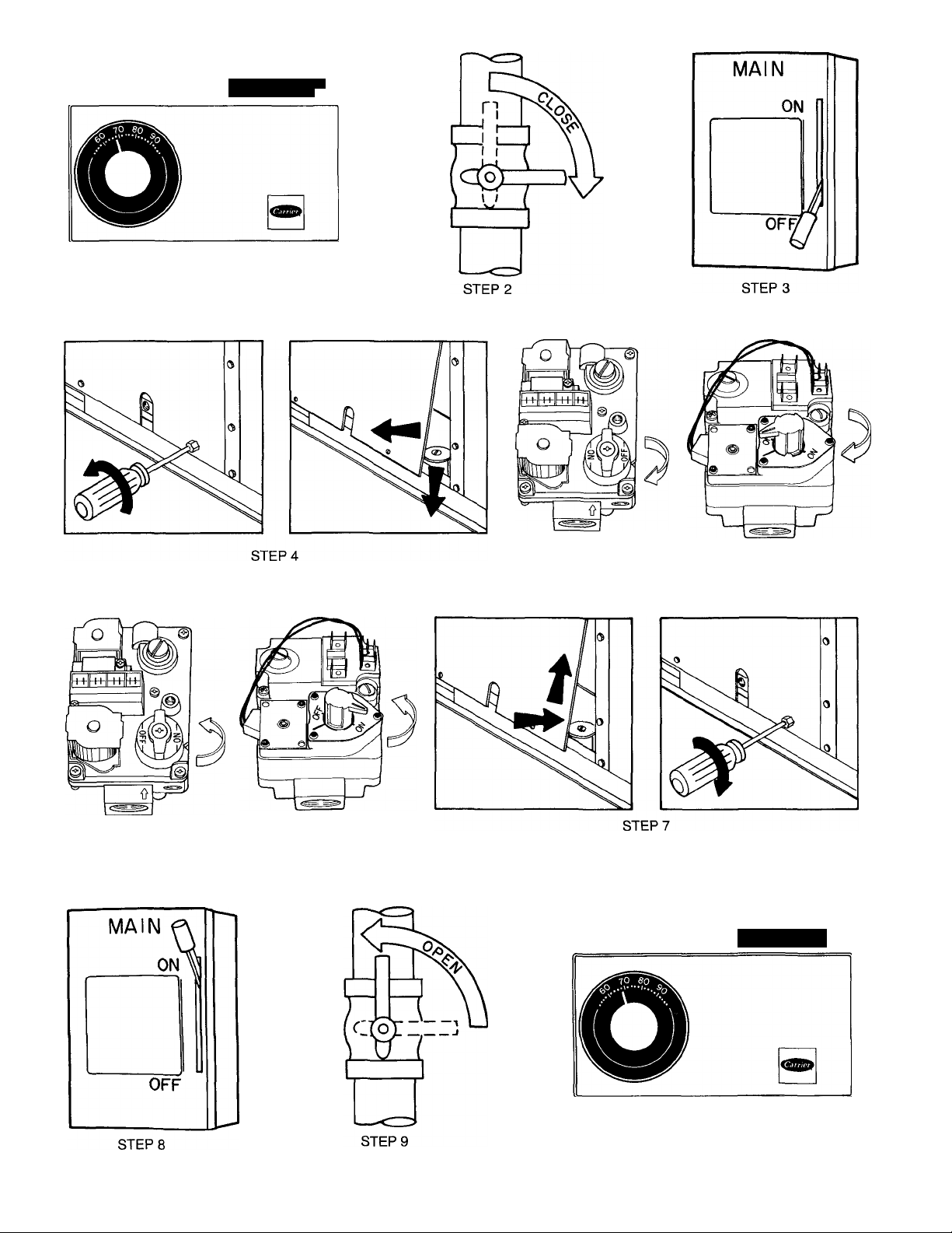
See Fig. 1 for location of gas valve. Refer to Fig. 2 while
proceeding with the following steps.
Step 1 -
setting and
Step 2 Step 3 —
Step 4 —
Step 5 —
wise
Step 6 —
wise'
Set room thermostat to the lowest temperature
set SYSTEM switch to HEAT position.
Close the manual gas valve.
Turn off the electrical supply to the unit.
Remove the burner compartment access panel.
Turn the control dial on the gas valve clock-
to the OFF position and wait 5 minutes.
Turn control dial on gas valve counterclock-
to the ON position.
Step 7 — Replace the burner compartment access panel.
Step 8 — Turn on the electrical supply to unit.
Step 9 — Open the manual gas valve.
Step 10 — Set room thermostat selector slightly above room
temperature to start unit. The induced-draft combustion air
fan will start. Main gas valve will open and main burners
should ignite within 4 seconds. If the burners do not light,
there is a 60 second delay before another 4 second try. If
the burner still does not light, the time delay is repeated. If
the burner does not light on the 11th attempt, there is a
lockout. Repeat Steps 1 - 10. If burners still do not light,
call for service.
Step 11 — Set the temperature selector on room thermo
stat to desired setting.
A WARNING
If the main burners fail to light, or the blower fails to
come on, shut down gas heating section and call your
dealer for service. Failure to follow these requirements
could result in serious personal injury.
BURNER ACCESS PANEL
Manufacturer reserves the right to discontinue, or change at any time, specifications or designs without notice and without incurring obligations.
Book|1 |4 PC 111 Catalog No 564-906 Printed in U.S A Form 48D,L-2SO Pg 1 10-91 R eplaces: 48D,L-1 SO
Tab la 6a
Page 2
STEP 1
'T a
\\ \ ‘ \ \ \ \ » \ l \ \ > U l h H I
50 60 70 80
48DJD,LJD005-009
48DJE,LJE004-007
48DJD,LJD005-009 48DJD.LJD012,014
48DJE;LJE004-007 48DJE.LJE008-012
STEPS
48DJD,LJD012,014
48DJE,LJE008-012
STEPS
50 60 70 80
Fig. 2 — To Light Unit
STEP 10
Page 3

TO SHUT UNIT OFF
A WARNING
1. Do not turn off the electrical power to unit without
first turning off the gas supply.
2. Never attempt to manually light the main burners on
unit with a match, lighter, or any other flame. If the
electric sparking device fails to light the main burn
ers, refer to the following shutdown procedures, then
call your dealer as soon as possible.
Failure to follow these procedures can result in serious
fire or personal injury.
Refer to Fig. 3 while proceeding with the following steps.
ROUTINE MAINTENANCE AND CARE
FOR THE EQUIPMENT OWNER
Before proceeding with those things you might want to
maintain yourself, please carefully consider the following:
A WARNING
1. TURN OFF GAS SUPPLY AND THEN ELECTRI
CAL POWER TO YOUR UNIT BEFORE SERVIC
ING OR PERFORMING MAINTENANCE.
2. Do not turn off electrical power to this unit without
first turning off the gas supply.
3. When removing access panels or performing main
tenance functions inside your unit, be aware of sharp
sheet metal parts and screws. Although special care
has been taken to reduce sharp edges to a minimum,
be extremely careful when handling parts or reach
ing into the unit.
Step 1 — Set room thermostat to lowest temperature set
ting and set SYSTEM switch to OFF.
Step 2 — Close the external manual gas valve.
Step 3 — Turn off electrical power supply to unit.
Step 4 — Remove the burner compartment access panel.
Step 5 — Turn the control dial on the gas valve clock
wise Q to the OFF position.
Step 6 — Replace the burner compartment access panel.
Step 7 — If unit is being shut down because of a malfunc
tion, call your dealer as soon as possible.
If unit is being shut down because the heating season has
ended, restore electrical power to the unit to ensure opera
tion of the cooling system during the cooling season.
Should overheating occur, or the gas supply fail to shut
off, shut off the manual gas valve to the unit before shut
ting off the electrical supply.
Do not use this unit if any part has been under water.
Immediately call a qualified service technician to inspect
the unit and to replace any part of the control system and
gas control which has been under water.
MAINTAINING YOUR UNIT
All maintenance should be handled by skilled, experi
enced personnel. Your dealer ean help you establish a stan
dard procedure.
For your safety, keep the area around the unit clear and
free of combustible materials, gasoline and other flamma
ble liquids and vapors.
To assure proper functioning of the unit, the flow of com
bustion and ventilating air must not be obstructed from reach
ing the unit. Clearance of at least 3 ft on flue and condenser
sides and 6 in. on all other sides is required.
Air Filter(s) — Air filter(s) should be checked at least
every 3 or 4 weeks and changed or cleaned whenever they
become dirty. Table 1 indicates the correct filter size for
your unit. See Fig. 4 for filter access door location.
To replace or inspect filters:
1. On 48DJD,DJE units, lift open the filter access door and
lift and pull the filter track until it falls toward you. On
48LJD,LJE units, remove screws on filter access panel
and remove panel. Lift up filter track and pull track un
til it falls toward you. If the 48LJD,LJE unit has a fieldinstalled accessory filter access door, follow instructions
above for 48DJD,DJE units.
2. Remove the left filter by pulling outward from the track.
3. Slide the right filter over to the left and then remove.
When installing filters, note the direction of airflow ar
rows on the filter frame.
NOTE: It is recommended that filters be field installed out
side of the unit on horizontal economizer/two-position damper
applications. Otherwise, the economizer/two-position damper
will have to be partially removed to access the filters. The
area of the field-installed filters should be equal to the area
of the factory-installed filters as shown in Table 1.
If you have difficulty in locating your air filter, or if you
have questions concerning proper filter maintenance, con
tact your dealer for instructions. When replacing your unit
filters, always use the same size and type of filter that was
originally supplied by the installer.
Units with outdoor air capability have a cleanable filter
for the outdoor air. This filter should be checked annually
and cleaned as necessary with steam or hot water and a
mild detergent. Do not use disposable filters in place of
cleanable filters.
A WARNING
Never operate your unit without filters in place. Fail
ure to heed this warning may result in damage to the
blower motor and/or compressor. An accumulation of
dust and lint on internal parts of your unit can cause
loss of efficiency and, in some cases, fire.
Table 1 — Indoor-Air Filter Data
UNfT SIZE
48DJD/DJE
48UD,LJE
004-007
008,009 4 16x20x2
012,014
NOTE: Replacement filters should be UL (Underwriters’ Laborato
ries) certified or equivalent.
INDOOR-AIR FILTERS
(Disposable Fiberglass)
Quantity Size (in.)
2 16x25x2
4 20 X 20 X 2
Page 4

STEP 1
jCi
50 60 70 80
_
S-
48DJD,UD005-009
48DJE.UE004-007
Fig. 3 — To Shut Unit Off
48DJD,LJD012,014
48DJE.LJE008-012
STEPS
Page 5

FILTER ACCESS DOOR
48DJD.DJE
FILTER ACCESS PANEL
48LJD,LJE
Fig. 4 — Filter Access Door/Panel Location
Heat Exchanger — To ensure dependable and effi
cient heating operation, the heat exchanger should be checked
by a qualified maintenance person before each heating sea
son, and cleaned when necessary. This checkout should not
be attempted by anyone not having the required expertise
and equipment to do the job properly. Checking and/or clean
ing the heat exchanger involves removing the gas controls
assembly and the flue collector box cover and, when com
pleted, reinstalling the gas controls assembly for proper op
eration. Also, the flue collector box cover must be replaced
correctly so that a proper seal is maintained. Contact your
dealer for the required periodic maintenance.
Fans, Belts, and Fan Motor — Periodically check
the condition of the fan wheels and housings, belt tension
and fan motor shaft bearings. No lubrication of condenser
or evaporator fan bearings or motors is required or recom
mended.
Evaporator and Condenser Coils — Cleaning of
the coils should be done by qualified service personnel. Con
tact your dealer for the required annual maintenance.
Condensate Drain — The drain pan and condensate
drain line should be checked and cleaned at the same time
the cooling coils are checked by your dealer.
Compressor — All compressors are factory shipped
with a normal charge of the correct type of refrigerationgrade oil in them and should not require additional oil.
Condenser Fan
A WARNING
Do not poke sticks, screwdrivers, or any other object
into revolving fan blades. Severe bodily injury may re
sult.
The fan must be kept free of all obstructions to ensure
proper cooling. Contact your dealer for any required ser
vice.
Electrical Controls and Wiring — Electrical con
trols are difficult to check without proper instrumentation;
therefore, if there are any discrepancies in the operating cy
cle, contact your dealer and request service.
Combustion Area and Vent System — The com
bustion area and vent system should be visually inspected
before each heating season. The normal accumulation of
dirt, soot, rust, and scale can result in loss of efficiency and
improper performance if allowed to build up.
A CAUTION
If your unit makes any unusual or especially loud noises
during heating, shut down the heating section and call
your dealer.
See Fig. 4 and 5 and proceed as follows to inspect the
combustion area and power-venting system of your unit.
1. Turn off gas supply to your unit.
2. Turn off electrical power to your unit.
3. Remove burner compartment access panel.
4. Using a flashlight, carefully inspect the burner areas for
dirt, soot, rust or scale.
A CAUTION
If dirt, soot, rust, or scale accumulations are found,
call your dealer and do not operate your heating
section.
When you have completed your inspection, follow the
5.
start-up procedures in this manual to restore your unit to
operation.
Observe unit heating operation.
A WARNING
Components in heat section may be hot after unit
has been started up. When observing flame, be care
ful not to get close to or touch heating components
or serious personal injury may result.
Watch the burner flame to see if it is bright blue. If you
observe a suspected malfunction or that the burner flame is
not bright blue, call your dealer.
7. Replace burner compartment access panel.
Refrigerant Circuit — The refrigerant circuit is dif
ficult to check for leaks without the proper equipment; there
fore, if inadequate cooling is suspected, contact your local
dealer for service.
Unit Panels — After performing any maintenance or
service on the unit, be sure all panels are securely fastened
in place to prevent rain from entering unit cabinet and to
prevent disruption of the correct unit airflow pattern.
Page 6

a. 48DJD005-007, 48DJE,LJE004-007,
48LJD004-007
b. 48DJD/LJD008-014, 48DJE,LJE008-012
INDUCED-DRAFT
BLOWER
INDUCED-DRAFT
MOTOR
GAS VALVE
INDUCED-DRAFT
BLOWER
INDUCED-DRAFT
MOTOR
GAS VALVE
(HIDDEN)
REGULAR DEALER MAINTENANCE
In addition to the type of routine maintenance you might
be willing to perform, your unit should be inspected regu
larly by a properly trained service technician. An inspec
tion (preferably each year, but at least every other year)
should include the following:
1. Inspection of all flue product passages — including the
burner, heat exchanger, and flue collector box.
2. Inspection of all combustion- and ventilation-air
passages and openings.
3. Close inspection of all gas pipes leading to and inside
your unit.
4. Inspection, and if required, cleaning of the condenser
and evaporator coils.
5. Inspection, and if required, cleaning of the condensate
drain pan.
6. Inspection and cleaning of blower wheel housing and
motor.
7. Inspection of all supply- and retum-air ducts for leaks,
obstmctions, and insulation integrity. Any problems found
should be resolved at the time of inspection.
8. Inspection of the unit base for cracks, gaps, etc., which
may cause a hazardous condition.
9. Inspection of the unit casing for signs of deterioration.
10. Inspection of all electrical wiring and components to
assure proper connection.
11. Inspection for leaks in the refrigerant circuit. Pressurecheck to determine appropriate refrigerant charge.
12. Operational check of the unit to determine working con
ditions. Repair or adjustment should be made at the
time of inspection.
Your servicing dealer may offer an economical service
contract that covers seasonal inspections. Ask for fur
ther details.
Complete service instructions can be found in the unit
Installation, Start-Up and Service Instructions.
f
Fig. 5 — Heat Section Detail
Page 7

BEFORE YOU CALL FOR SERVICE,
CHECK FOR SEVERAL EASILY SOLVED
PROBLEMS
If insufficient heating or cooling is suspected:
( ) Check for sufficient airflow. Check the air filter for
dirt. Check for blocked return- or supply-air grilles. Be sure
they are open and unobstructed. If these checks do not re
veal the cause, call your servicing dealer.
If your unit isn’t operating at all, check the following list
for easy solutions:
( ) Check to be sure that your thermostat temperature se
lector is set above the indoor temperature during the heat
ing season, or below the indoor temperature during the cooling
season. Be sure the SYSTEM switch is in the proper HEAT
or COOL position and not in the OFF position.
( ) Is the electrical supply switch ON? Are any fuses blown,
or has the circuit breaker tripped?
( ) During the heating season, check the external manual
shutoff valve. Is this lever parallel with the pipe, indicating
that the valve is open? Or is the lever at the right angle,
indicating that the valve is closed? If closed, has the gas
been shut off for safety reasons? Otherwise, you may open
the valve and follow the start-up procedures listed in this
manual.
NOTE: Before proceeding with the next check, turn OFF
the electrical power supply to the unit. Remove the control
access door.
( ) During the heating season, check the control dial on
the gas valve. Is it in the ON position? If it is not, be sure
it has not been turned off for the purpose of safety. If noth
ing else seems to be amiss, follow the start-up procedures
in this manual.
( ) If your unit still fails to operate, eall your servicing
dealer for troubleshooting and repairs. Specify the model
and serial numbers of your unit. (Record them in this man
ual in the space provided.) If the dealer knows exactly which
unit you have, he may be able to offer suggestions over the
phone, or save valuable time through knowledgeable prep
aration for the service call.
IN CASE OF TROUBLE
If, after performing the above, unit performance is un
satisfactory, shut off the unit and call your dealer.
Dealer’s Name
Telephone No._______________________________________________
Unit Model
Unit Serial Number.
______________________________________________
_________________________________________________
Page 8

Copyright 1991 Carrier Corporation
Manufacturer reserves the right to discontinue, or change at any time, specifications or designs without notice and without incurring obiigations.
Book|1 |4 PC 111 Cataiog No 564-906 Printed in U S A. Fo rm 48D,L-2SO Pg 8 10-91 Replaces: 48D,L-1 SO
Tab la 6a
 Loading...