

Page 1
Number One
AirConditioniiX)
Maker
e
Division of Cairier Corporation
Syracuse New York
r
Combination Heating/Cooling Units
INTRODUCTION
The 48DH, DL and DM combination heating/
cooling units are complete systems designed for
outdoor installation on slab or rooftop.
Installation consists of: rigging and mounting
the unit; attaching ductwork; making single gas,
electrical and condensate connections; and attach
ing thermostat leads. A field-furnished filter rack is
required in the return air stream.
RECEIVING THE UNIT
Examine the unit carefully for any damage
incurred in shipment. If found, file claim with
transportation company immediately.
Check unit nameplate to ensure that unit
electrical requirements match available power
supply, and that unit is designed for use with the
proper gas type (natural or liquefied petroleum).
Leave unit on shipping skids until ready for
mounting.
INSTALLATION
Check national and local gas and electrical
codes and local building codes for any special
installation requirements.
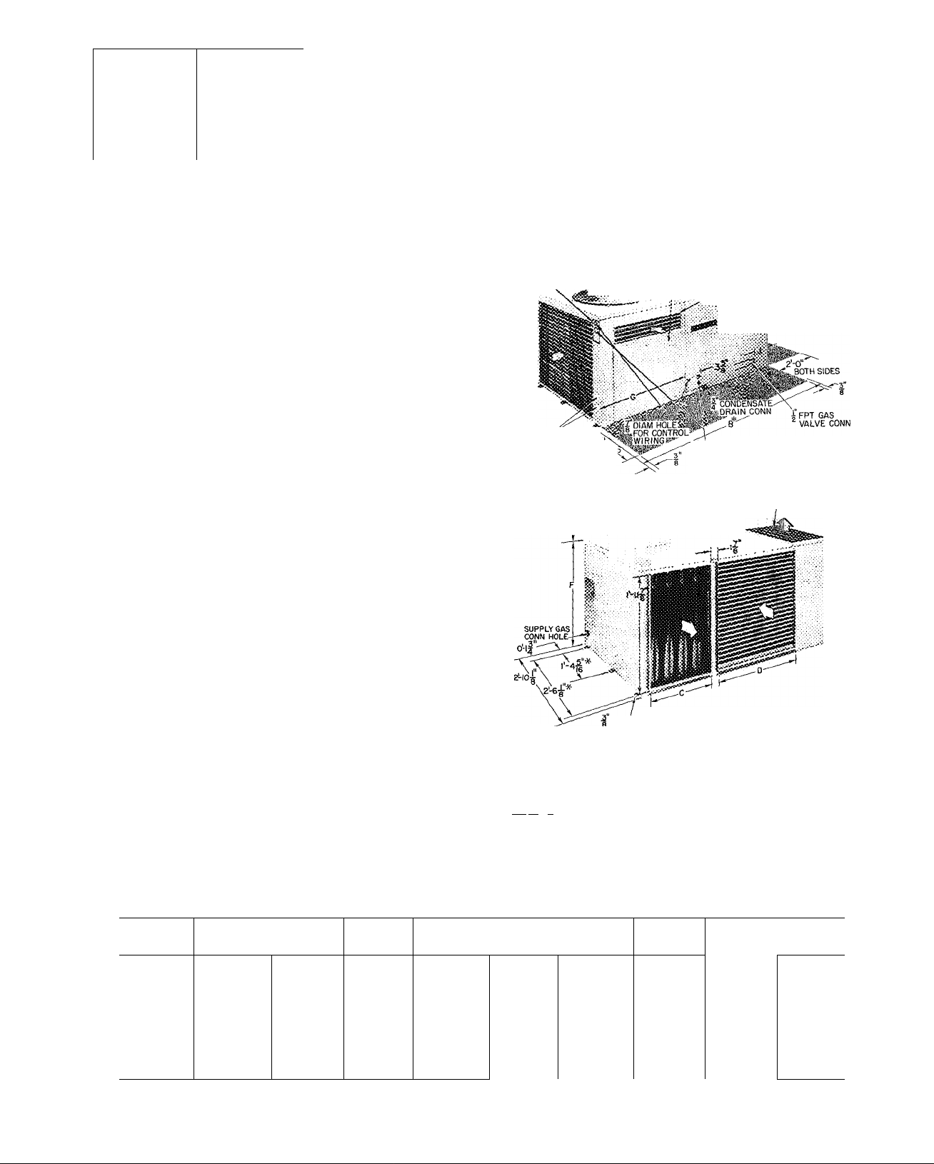
Unit Location — Install unit outdoors and as close
to building duct openings as possible. Unit may
face in any direction since neither the condenser
air inlet nor the flue outlet (Fig. 1) are affected by
wind. Do not locate unit near sources of con
taminated air.
Although the unit is weatherproof, position
unit so that water and ice from roofs or eaves
cannot fall directly on the unit.
SPACE LIMITATIONS - Provide sufficient space
for unimpeded air flow and for wiring and servicing
unit (Fig. 1).
, CONO UNIT
2-0 OVERHEAD SPACE SECTION
REQ FOR SERVICE AND ACCESS PANEL
AIR FLOW ;
002
'only .
SERVICE ^
OPENINGS ^0'
ACCESS SIDE
*This dimension is not applicable to 002 units because there are no
mounting rails
ta-'iiEiEJ ance space of 1 in. on duct connection side, and 12 in on
BOTH side:
FLUE OUTLET
—,—X::...
Space required for service Design certified by A G.A. for installation on combustible type floor with a minimum ciear-
remaining sides
Indoor (Evaporator) Air
O'
____WIND CAP ASSEMBLY (CONDENSER AIR OUTLET
îLÎÎÎ 002 UNIT ONLY)
• DIAM*
(SmTG HOLES)
COMBUSTION AIR
.JSSiiSOc 045 8005
n DIAM HOLE
® FOR LINE
POWER WIRING
HEATING
SECTION
i ACCESS PANEL
) Condenser Air
Fig. 1 — Physical Data
Table 1 — Base Unit Dimensions (ft-in.)
UNIT
A 3-10
В
C
D
E
F
G
H 0-11У 0-11У
J
*Refer to Table 2 for differences of these series
48DL 48 DH 48DL 48DL 48 DM
002* 003
— —
0-10V3
0-11 Уз
1- 0
2- 2У
— —
0- 4 0- 4
3-10
0-1 оу 0-юу 0-1 оу
0-11 у
1- 0 1- 0 1- 0
2- 2%
4- 7 4- 7
4- 7% 4- 7%
1- 2
2- 2У
2- 2У
0-11У 0-11У
0- 4
1- 8
2- 2У
2- 2У
0- 4
48 DH 48DL
004
3_2
5-2У 5- 2% 5- 2%
1-ЗУ
1-8 1- 8
1-0
2-2У
2-4У 2- 2Ув 2- 4У
1-4У
0-7У
5- 2 5- 2
1- 5У
1- 0
2- 2У
1- 4У 1- 4У
0-11
Q45
1- ЗУ
1-11 1-11
1- 0
2- 2%
0- 7У
48DL
5- 2
5- 2У
1- ЗУ
1- 0
2- 2% 2- 2У
2- 4У
1- 4У
0- 7У
48DH
005
5- 7\
5- 8У
1 9
1-11
1- оу
2- 4У
1- 4У
1- 2У
Form 48DH-6
Page 2
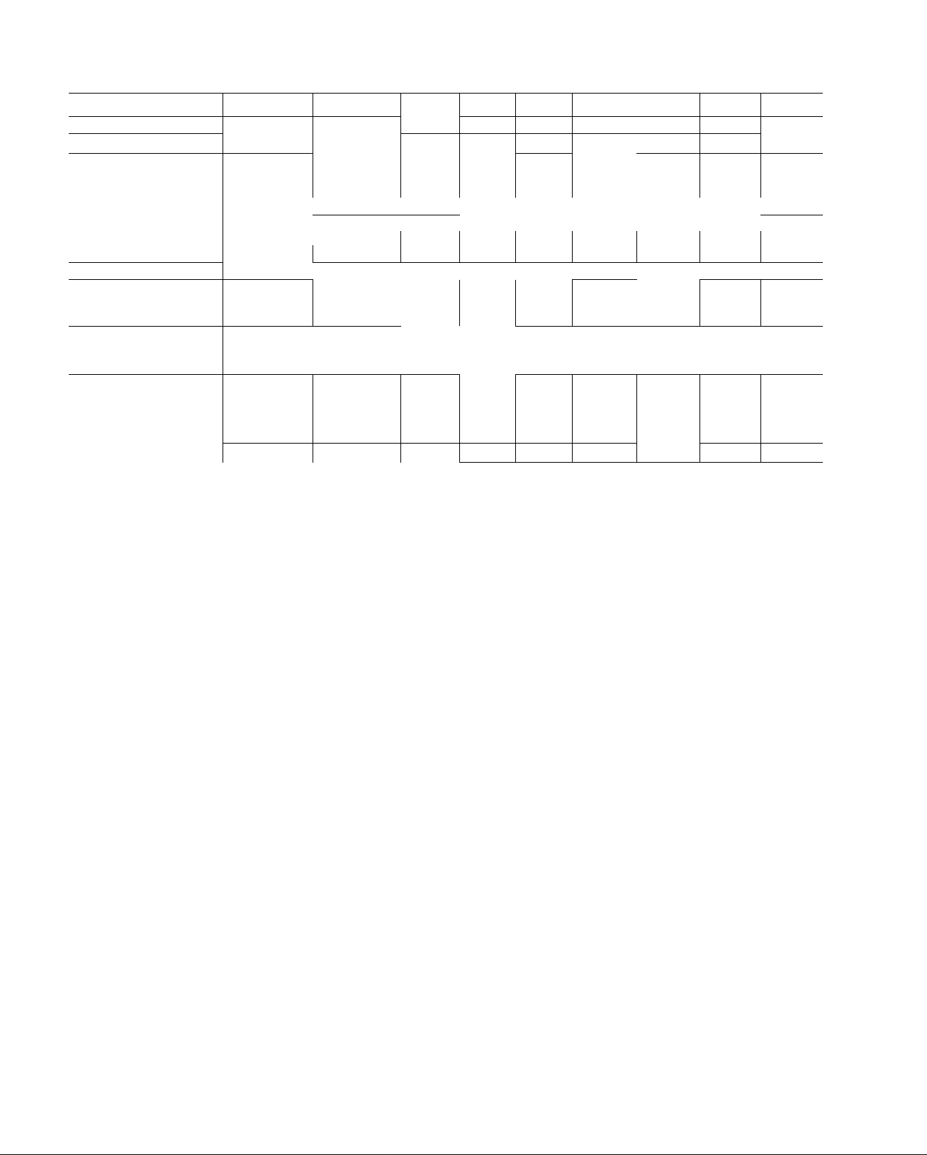
Table 2 — Physical Data
UNIT
OPERATING WT (lb)
REFRIG (22) CHG (Ib-oz)
COMPRESSOR
Cyl inders 2
Rpm (60-Hz)
CONDENSER FAN
Air Quantity (Cfm)
Motor Hp
EVAPORATOR FAN
CAPACITY (1000 Btuh)
Cool in g
Input Heotlng/Bonnet*
MAX EXTERNAL
STATIC PRESSURE
Heating (in. W.C.)
FILTERSt (1-in. thick)
Disposable — No. .. 1 15x20 1 15x20
Size (in.) 1 .20x25 1 20x25 2 15x20 1 20x20
Permanenti — No. ..
Size (in.)
HEAT TEMP RISE (F)
* Ratings shown for elevations up to 2000 ft above sea level. For ele
vations above 2000 ft deduct 4% capacity for each 1000 ft above
sea level
48DL002
331
3.2
M27 (1-ph) M27 (1-ph)
AHbbz^/h(J-ph) AH5527h(3-ph)
1700 1700
Vs
24 24 30 36
56/42
1 15x20 1 15x20 1 20x20
35-65 45-75
48DH002 48DL003
343 385
3 2 3.6 5 1
2 2 2
Propel ler-Type — Direct Drive; Vertical Disc
Vs Vs
Centrifugal —
80/60
80/60
48DL004
M34 M40
2000 2500
Direct Drive; Horizontal Discharge
80/60
1 20x20 1 20x20 1 .20x20
35-65 35-65
i Recommended field-supplied filter
ifBased on 0.082 in. wg pressure drop or less thru filter at 520 ft/min
48 DM004
411
3500
Vs
110/82 5 125/93 75
40
1 20x20 1 .20x20 2 20x20
face velocity.
48DH004
430
5 1
M40
2
2500 2500 2700
Vs
36
35-65 45-75
438
M40 P46
2 2
Vs
36
1 15x20
48DL045 48DL005 48DH005
450 476
5 2 5 1 5 1
large
Vs
Г
42 48
100/75
1 20x25
35-65
P53
2
2700
V,
110/82 5
1 20x25
1 25x25
2 15x20
35 65
512
P53
2
2700
Vs
48
150/112 5
1 20x25
1 .25x25
2 15x20
45-75
OUTSIDE AIR LIMITATIONS - Although there
are no restrictions on either the percentage or the
temperature of the outside air circulated thru the
unit, the rate of moisture condensation from the
combustion process increases significantly when
return air temperature drops below 50 F. Protect
the drain holes in the bottom pan against ice
buildup if outside air of below freezing tempera
ture is used
VIBRATION ISOLATION -- The unit compressor,
evaporator fan and condenser fan are mounted on
isolators to minimize vibration. Additional isola
tion is not required for slab mounting. With some
types of roof construction, however, the use of
field-furnished mbber pad type isolators may be
advisable.
Unit Rigging
1. Sling the unit perpendicularly to shipping skid
mnners. Use spreader bars to prevent damage
from sling or cable.
2. Raise unit to desired location and remove
shipping skid.
3. Mount and level the unit as indicated in Unit
Support and Mounting section.
Unit Support and Mounting
LEVELING THE UNIT — Level the unit from end
to end but pitch the unit slightly (3/8 to 1/2 in )
towards the condensate drain on the service access
face of the unit (Fig. 1). Use the unit frame as a
leveling reference.
SLAB MOUNTING — Mount the unit on a
concrete pad, cement blocks, bricks or creosoted
wood of sufficient area and strength to support the
unit weight (Table 2) without distortion or damage
and maintain the drainage pitch recommended
above.
A gravel apron will prevent grass and foliage
from obstructing the condenser air inlet (Fig. 1).
FLAT OR RECESSED ROOF MOUNTING should
be as close as possible to the roof duct opening
Place the unit on at least 2 wooden 2x4 in. or
2x6 in. sleepers.
Sleepers may be perpendicular to or parallel to
the unit mounting rails, but must span at least 2
roof joists or purlins to distribute unit weight. Set
the sleepers in roof cement or mastic. Do not plug
drain holes in the compressor or furnace
compartment.
Do not support the unit by the ends of the base
rails, nor use vibration isolators at these points.
Unit will not be properly supported and could sag
in the middle.
PITCHED ROOF MOUNTING -- Constmct a
sturdy welded or bolted frame of
1-1/2 X 1-1/2 X 1/4 in. or larger angle iron, with
frame members at right angles to unit rails. Make
provisions for securing unit to frame. Use roof
cement or mastic where frame is in contact with
roof.
%
Page 3
r
Ductwork Installation — For air duct system design
information, refer to Carrier System Design Man
ual, Part 2. System air flow must be within the
range of temperature rise and external static
pressure shown on the unit A.G.A. rating plate.
Bolt or screw ductwork to unit supply and
return air duct flanges and seal joints with sheet
metal flashing. Flange location and dimensions are
given in Fig. 1 and Table 1. Use flexible connectors
between ductwork and unit to dampen vibration.
If a single split duct is connected to the unit, use a
gasket to prevent air bypass between supply and
return sides.
Insulate and weatherproof all external duct
work. Secure ducts to building structure and
weatherproof all duct openings in wall or roof.
Ducts passing thru unconditioned spaces must be
insulated and provided with a vapor barrier.
Filter Installation (Field-Supplied)
1. Locate filter in return air system. Convenient
location for filter is inside building behind
return air grille. Size and number of required
filters is given in Table 2.
2. Attach filter manufacturer’s instructions to
filter rack.
retaining clip on the unit top cover. Fasten the
inlet box with sheet metal screws provided.
2. Place end of heat-shield collar (item 2) over top
cover extrusion.
3. Slide flue pipe into heat-shield collar and secure
wind cap assembly (item 1) with 3 sheet metal
screws thru wire cage eyelets.
WIND CAP
ASSEMBLY
FLUE PIPE
(PART OF WIND CAP
ASSEMSLY)
£Y£LETS(3)
■JXHEAT-SHIELC
^COLLAR
COMBUSTION
AIR INLET BOX
RETAINJNO
CLIP
TOP COVER
OF UNIT
ASSEMBLE WIND CAP AND
COMBUSTION-AIR INLET BOX
Locate — The wind cap assembly, heat-shield collar
and combustion-air inlet box (items 1, 2 and 3 of
Fig. 2) are shipped within the condenser section of
all size 003 thru 005 units except 460 volt unit.
On 460 volt, size 003 thru 005 units, only the
combustion-air inlet box is shipped within the
condenser section. The heat-shield collar and wind
cap assembly are shipped in a separate package.
On size 002 units of any voltage, the
combustion-air inlet box is inside the unit behind
the heating section access panel (Fig. 1). The
heat-shield collar and wind cap assembly are
shipped in a separate package.
Remove — On size 002 units, remove the heating
section access panel (Fig. 1) and obtain the
combustion-air inlet box.
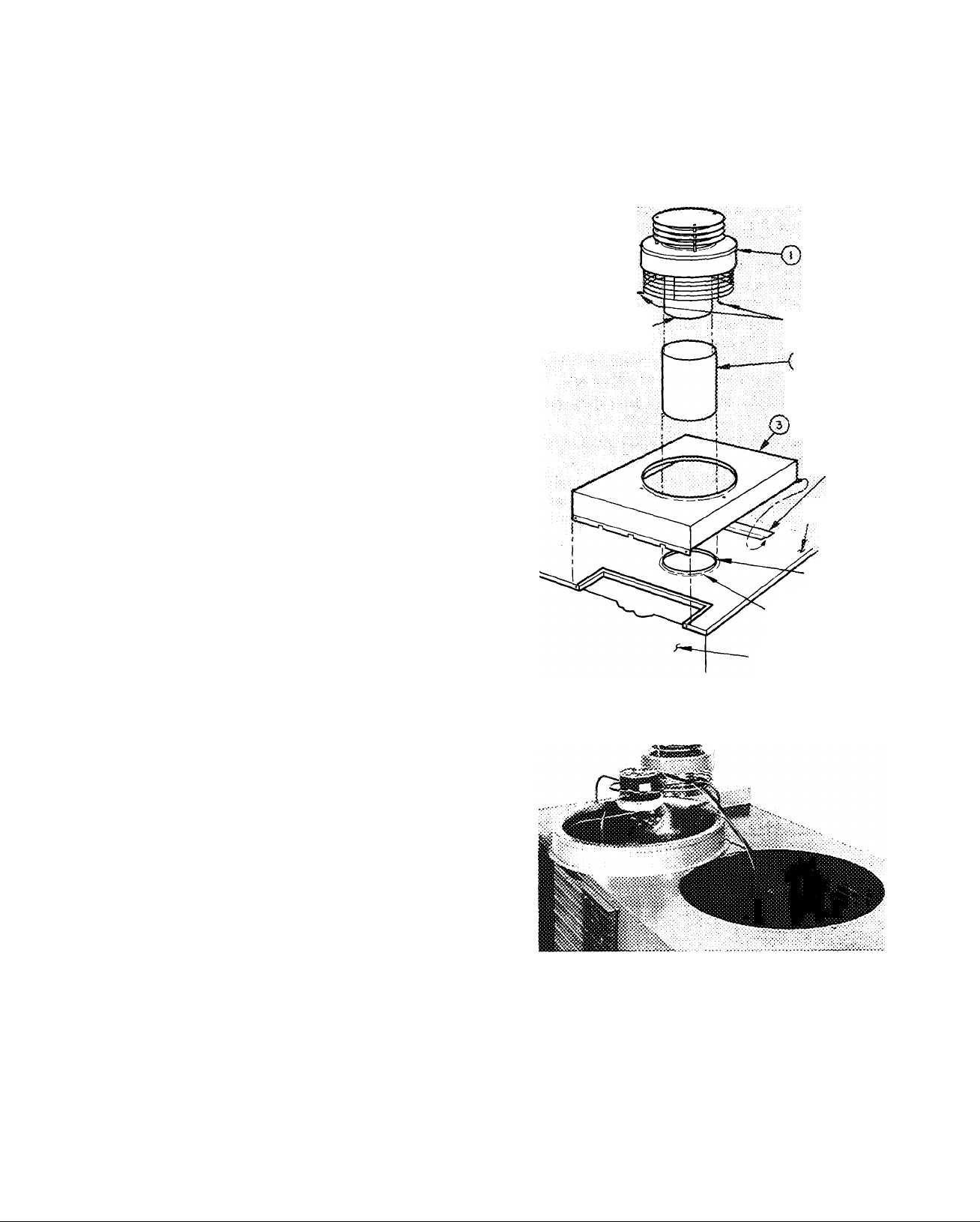
On size 003 thru 005 units, remove 6 sheet
metal screws and lift condenser fan, grille and
orifice from the top of the condenser section (Fig.
3). Remove and discard metal banding securing the
wind cap and/or inlet box and remove the item(s)
from the condenser section.
Before replacing the condenser fan, grille and
orifice, remove any shipping tape from the con
denser fan.
Assemble (Fig. 2)
1. Mount the combustion-air inlet box (item 3) by
sliding the horizontal box flange under the
TOP COVER
EXTRUSION
FLUE BOX
EXTRUSION
HEATING SECTION
ACCESS PANEL
Fig. 2 — Wind Cap and Air Inlet Box Assembly
Fig. 3 — Removing Condenser Fan
and Orifice Assembly
PIPING AND WIRING
Gas Piping — Install piping per national and local
codes and ANSI Z223.1 entitled “Installation of
Gas Appliances and Gas Piping,” (published by
American Gas Association, 1515 Wilson Blvd.,
Arlington (Rosslyn), Va. 22209).
Page 4
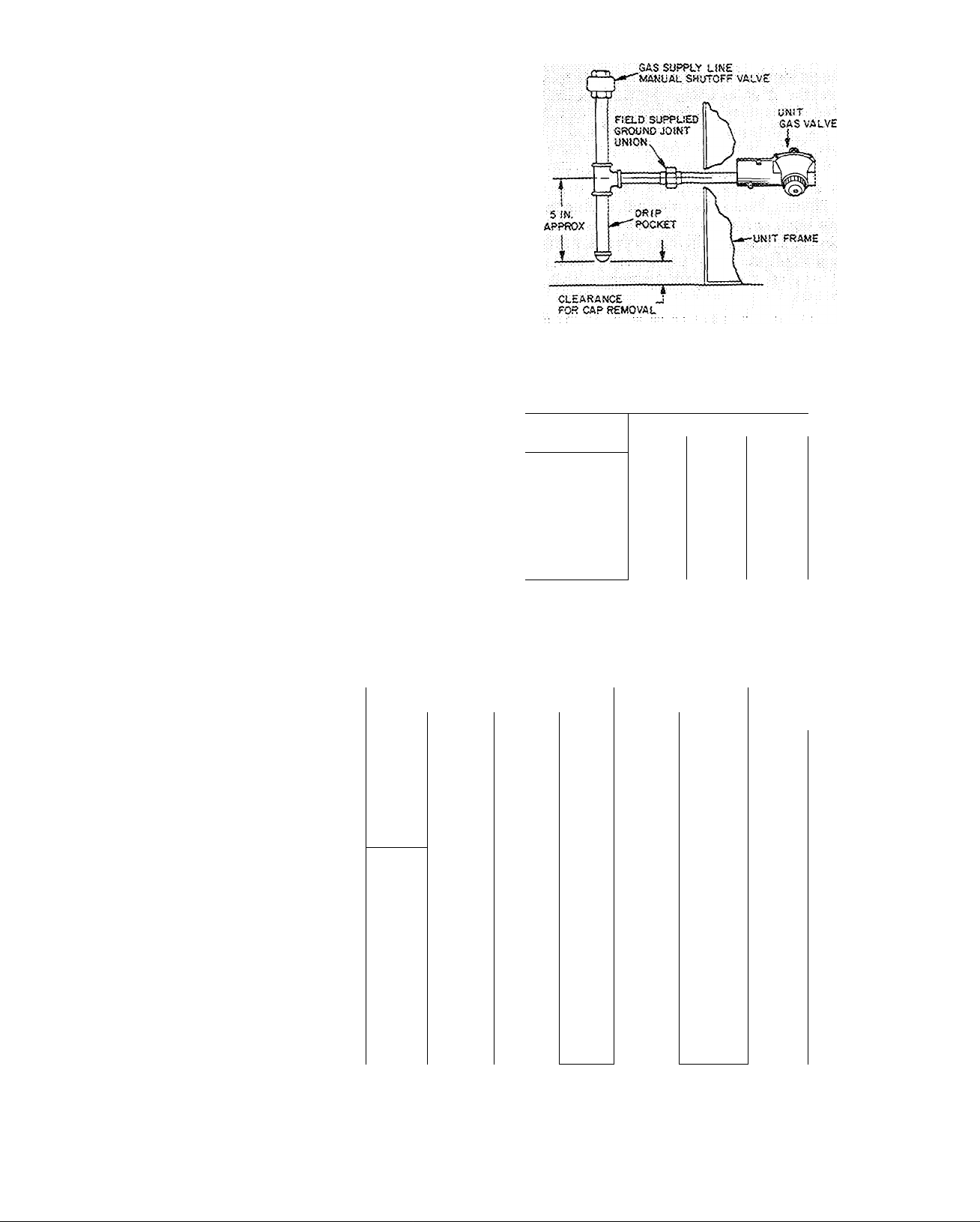
1. Furnish the gas line from the main gas supply
to the unit gas valve (Fig. 4).
2. Size the supply pipe for 0.3-in. wg maximum
pressure drop and for the volume of gas
required (Tables 3, 5 and 6). Pipe size must
equal or exceed size of gas connection at unit.
3. Use pipe dope approved for use with liquefied
petroleum (LP) gases.
4. Pitch all horizontal pipe runs towards the unit
1/4 in. per 15 ft to prevent trapping condensed
moisture.
5. Support piping to maintain proper pitch,
prevent strain on unit controls, and prevent
accidental movement of piping.
6. Install a tee for attachment of a dirt and
moisture drip pocket (Fig. 4). Tee should be at
same level or below gas valve connection. Drip
pocket must be protected against freeze-up.
7. Install manual shutoff valve on gas piping per
local codes.
8. Provide a ground joint union in the gas supply
line near the unit gas valve.
9. Protect gas piping from freezing temperatures.
Gas stoppage can result from failure to insulate
pipe against wide or sudden temperature
changes.
10. When piping is completed, check entire gas
assembly and field piping with soap and water
solution.
Never use an open ñame for leak testing.
Fig. 4 — Gas Piping Details
Table 3 — Maximum Pipe Cap. (cfh)^
PIPE
LENGTH (ft)
10
20 92
30 73 152
40 63 130 245
50
60
70
80
90
100
*Cfh — Cu ft/hr based on 0.3 in. wg pressure drop and 0.6 gas
specific gravity.
NOTE;
Correction is not necessary for normal number of fittings nor
for 0.7 gas specific gravity unless specified.
NOMINAL PIPE SIZE
V.
132
56 115
—
_
—
-
V
/4
278
190
105
96
90
84 160
79
1
520
350
285
215
195
180
170
150
1V4
1050
730
590
500
440
400
370
350
320
305
Table 4 — Electrical Data (60-Hz)
UNIT
Model Serie
48DL,DH
002
200
300
400
200
48DL
003
300
400
500
^00
48DL,DH,
DM004
48DL
045
300
400
500
600
200
300
400
500
600^
200
48DL,DH
005
FLA — Full Load Amps
FU — Dual Element Fuse or Circuit Breaker having high inrush
capability (max allowable amps)
ICF — Max Instantaneous Current Flow during start-up is the sum
of compressor LRA plus the FLA of all other motors in
the unit.
300
400
500
600
VOLTAGE
Norn V/Ph
230/1
208/3
208/1
230/1
208/3
230/3
___ 460A3__
'^208/l~
230/1
208/3
230/3
460/3
208/1
230/1
208/3
230/3
460/3
'208/1^
230/1
208/3
230/3
460/3
WSA FLA ICF FU
23 5 19 5
21 6
16 8
29 8
27 3
18.8 15 5
17 4
8.8
39 0
35 9
25 0
23 3
11.3
41 0
36 5
27.4
24 5
12 4
46 5
41 5
29 5
25 2
13 3
17 9
14 0
24 3
22.3
14 4
32 4 117 9
29 9 105 9
21 2
19 8 75 9
34 1
30 5
23 2
20 9
38 5 132.6 60 31 9 126 0 3 8 2.8
34 5
24.9
21.5
11.3
UNIT
102.8
7 4 31 9
10.0
115 6 60
100 6 50 23 9 94 0
10 6
112 6
IFM
LRA
OFM
WSA
COMPR OFM
FLA LRA
83 4
75 4 30
58 4
91 8
73 8
63.8
85 9 30
39.0 15
85.6 35 16 6 79 0
73 6 30 14 3 67 0 3 8 2.8
38 3 15 7 3 35 0 3 8 2 8
93.6 40 18 3
76 6
38 3 20 8 0
35
20
40 20.8
35
25
25
15
50 26 5
45
20
50 27 9 106 0
35
Indoor (Evaporator) Fan Motor
Locked Rotor Amps
Outdoor (Condenser) Fan Motor
Wire Sizing Amps per NEC equals 1.25 x FLA of the largest
motor plus the sum of all other motors in the unit.
16 1 80 0
14 5
10 6 55 0
18.8
12 0 70 0
10 9
5 5 30 0
24 0
15 3 80 0
13 9 70 0
7 0 35 0
27 5
14 9 70 0
72 0
99 0
88.0
60.0
112,0
100 0
109 0
87 0
35 0
FLA
2 0 1 4
2 0
2 0
2 4
2 4
2 4
2 4
2.4 1 4
3 1 1
3 1
3 1 2 8
3.1
3 1 2.8
3 8 2.8
3 8
3 8 2 8
3 8 2.8
3 8 2 8
3 8
3 8 2.8
1 4
1.4
1 4
1 4
1 4
1.4
2.8
2.8
2 8
2 8
2 8
Page 5

Drain Piping — The condensate drain connection
(3/4-in. MPT) is on sei'vice access face of unit (Fig.
1) and attach to low voltage (control wiring)
terminals injunction box (Fig. 5 and 6).
1). Since drain is on the suction side of the indoor
(evaporator) fan, it must be trapped to prevent
f'
leakage back into the unit. Trap should be at least
3 in. deep and should be formed of flexible
material or in such a manner as to resist freeze-up
damage.
Wiring — The design center voltage for each unit is
stamped on the unit nameplate. The supply voltage
at the unit must be within ±10% of nameplate
voltage (see Table 4). Phase unbalance on 3-phase
units must be within 2%. Contact local power
company if correction is necessary. Operation of
the unit on improper line voltage or with excessive
phase unbalance is considered abuse and is not
covered by Carrier warranty.
THERMOSTAT COMBINATIONS FOR ALL UNITS
HH07AT074 AND SUBBASE HH93AZ076
HHOIA0042 AND SUBBASE HH93AZ042
HH0IAD040 AND SUBBASE HH93AZ042
-----
-----
-----
RED
BLU
BLK
ORN
BLK
YEL*'
riF-
FIELD
CONTRC
WIRES
Lie-
rk3_
POWERS -
0—
L2
1
002
UNITS
BLU
ONLY
Provide a branch circuit fused disconnect of
adequate size to handle unit starting current (Table
4). Disconnect must be within sight of and readily
accessible from the unit in accordance with Section
440-14 of the National Electrical Code (NEC).
Provision for locking switch at open (off) position
is advisable to prevent power from being turned on
while unit is being serviced.
Use only UL approved aluminum-copper con
nectors if aluminum power wires are used.
UNIT CONNECTION
1. Attach field power conduit to 1-1/8 in. hole at
front of high-voltage (line wiring) junction box
BRN I BLK
RED
BLU
ORN
LMPÍIÍ)
I I I I I I I I
I I
È ' È '
È ¿1 "w'iÌé's™"''"
FIELD CONTROL
WIRES
003,004, 045,005 UN ITS
I I Thermostat Connections
Splice Connection
'Not connected when single-phase power input is used
BLU —
— BLK -
-YEL^t.
I I I
___ Field Power Wiring
_____
Field Control Wiring
_____
Factory Wiring
(Fig. 1).
2. Run conduit so that control box can swing to
horizontal position for access to blower com
Fig. 5 — Remote Control Wiring
for Thermostat Combinations
partment (Fig. 6).
3. Splice field power wires to the pigtail leads in
the junction box. Wire nuts are provided for
either copper or aluminum wire. These must be
field insulated.
4. Route the control-voltage field wiring thru the
7/8-in. hole at front of low-voltage junction
box (Fig. 1). If conduit is not used, protect
wires by inserting diaphragm grommet into the
Make all connections to pigtail leads, but
hole.
do not use aluminum control wire for splice
connection to the copper pigtails.
Accessory Installation and Wiring
REMOTE CONTROL CENTER ^ The installation
instructions for this combination heating-cooling
thermostat and subbase are included with the
accessory.
Locate the thermostat on an inside wall or
column where it is affected only by the average
temperature of the room. The subbase has slots for
direct mounting on wall or on vertical outlet box.
Run the thermostat cable or equivalent single
leads of no. 18 colored wire from subbase termi
nals to 7/8-in. diam hole in access side of unit (Fig.
When thennostat wiring is complete, mount
thermostat to subbase per instructions included
with the control. Do not turn on unit power at this
time; refer to Start-Up section of this publication.
Thermostat heat anticipator setting is 0.6 amps
for natural gas units and 0.4 amps for LP gas units.
^ START CAPACITOR RELAY PACKAGE - This
accessory is available for those units requiring
boost start; see Check Compressor Start in this
publication. Installation instructions are included
with the accessory.
^ LP CONVERSION KIT - This accessory kit
contains the required components and instructions
for converting natural gas units to non-purge type
LP units.
HIGH CFM BLOWER PACKAGE is available when
500 cfm per ton cooling capacity is required. Refer
to price pages.
LOW AMBIENT 32LT FAN SPEED CONTROL
PACKAGE available for cooling operation down to
-20 F.
INDOOR FAN RELAY PACKAGE available for
size 002 units.
Page 6

START-UP
Unit Preparation — Do not apply power to the unit
before removing shipping supports as follows:
REMOVE BLOWER WHEEL SUPPORT (Fig. 6)
1. Remove heating section access panel.
2. Remove upper right side screw in control box
and swing control box downward as shown.
3. Loosen 5 screws and remove interior panel.
4. Loosen 3 motor bracket hold-down bolts by
about 1/8 in. (roughly 3 turns).
5. Grasp wooden slat (Fig. 6) with pliers and pull
slat out completely.
6. Swing hinged cover plate (Fig. 6) over slat hole
and secure with sheet metal screw.
7. Remove sheet metal screw holding outboard
blower housing support (Fig 6) and discard
support.
8. Check that blower wheel rotates freely. Do not
retighten motor bracket hold-down bolts
loosened in step 4.
9. Replace interior panel, control box and heating
section access panel.
OUTBOARD BLOWER
HOUSING SUPPORT
HINGED
COVERPLATE
2. Place thermostat selector switch at “Off’ and
set thermostat dial a few degrees below room
temperature.
3. Purge the gas supply line by loosening the
ground joint union (Fig. 4). Tighten the union
when gas odor is detected.
4. Remove the heating section access panel and
wait 5 minutes before proceeding.
5. Turn manual shutoff valve on main gas valve to
“Pilot” position.
6. Place thermostat selector switch at “Heat” and
set dial a few degrees above room temperature.
7. Pilot ignites.
8. Adjust pilot flame if not at the factory-set
length of 1-1/4 to 1-1/2 in. To adjust, remove
pilot adjusting screw cap on main gas valve (Fig.
8). Turn screw clockwise to increase and
counterclockwise to decrease flame length.
Replace cap.
If pilot does not ignite, gas pressure may be too
low. Refer to the applicable Start-Up Sequence for
required gas pressures.
If pilot fails to ignite on size 003 — 005 natural
gas units, check spark ignition system as described
in Service section.
NOTE: If pilot is extinguished for any reason,
ignitor will automatically attempt to rekindle
flame.
On size 002 units using natural gas, pilot
ignition is affected by the unit supply voltage.
Check the voltage and then adjust the glow coil
circuit as described below.
CONTROL WIRING'
LINE WIRING' ! —-CONTROL
WOODEN SLAT
Fig. 6 — Removal of Blower Wheel Support
REMOVE SHIPPING TAPE on condenser fan, if
not previously removed.
CHECK COMPRESSOR HOLD-DOWN BOLTS Compressor is internally spring-mounted. Do not
loosen or remove hold-down bolts.
SET HEAT ANTICIPATOR on thermostat at 0.6
amps for natural gas units, and at 0.4 amps for LP
gas units.
OPEN GAS SUPPLY LINE VALVE and purp line
by loosening ground joint union (Fig. 4). Tighten
union when gas odor is detected.
ADJUST BLOWER SPEED, if required, to main
tain heat temperature rise limits given in Table 2.
Change fan motor lead connection as shown on
label diagram.
CHECK AUTOMATIC PILOT
1. Turn power on.
GLOW COIL PILOT ADJUSTMENT - On size
002 units using natural gas, an automatic-reset
circuit breaker cycles the glow coil on and off
during pilot ignition. To ensure proper pilot
ignition, the length of the resistance wire in the
glow coil circuit must be compatible with the
voltage in the circuit. This wire is tagged and coiled
on the casing at the left of the gas manifold.
Measure the line voltage to the unit. Compare
the measured voltage with the following ranges and
cut off the length of resistance wire indicated:
above 232 V, none; 222 — 242v, 12in.;
212 — 232 V, 27 in.; 207 — 222 v, 36 inches. If the
measured voltage falls within 2 of these ranges, cut
off the shortest length.
If the thermostat wire is no. 18 gage, cut off
1 in. of resistance wire for each 2 ft of thermostat
cable length over 25 ft.
If other than no. 18 gage copper thermostat
wire is used, measure the resistance of one lead
from unit to thermostat. Multiply the resistance by
2. Then cut off resistance wire 1 in. per 0.032
ohms to equal the resistance of the thermostat
leads.
Page 7

Example: measured resistance .32 ohm x 2 - .64
.64 divided by 0.032 = 20
Cut off 20 in. of resistance wire.
CHECK MAIN BURNERS
1. Check automatic pilot as previously described.
2. Measure and adjust main burner gas input as
described in Service section.
3. Turn main gas valve to “On” position and
operate unit for at least 15 minutes with all
access panels in place.
4. Remove heating section access panel.
5. Turn each primary air adjustment screw (Fig. 7)
clockwise until yellow tips appear on burner
flames. Then turn each screw counterclockwise
(about 3/4 turn) until flames become clear,
almost transparent blue with a well defined
inner cone. If the flames lift off the burner
ports, turn the screw clockwise slightly.
BURNER ADJUSTMENT SCREW
FINAL HEATING SYSTEM CHECKOUT - Move
thermostat dial above and below room temperature
setting several times, pausing at least 5 minutes
between cycles. Check pilot flame, main burner
ignition, flame characteristics and indoor (evap
orator) fan motor time delay relay operation.
Replace heating section access panel.
COOLING SYSTEM CHECKOUT
1
.
Turn power on.
2.
Set room thermostat selector switch at “Cool”
or “Auto.” and dial setting below room
temperature.
3.
Move thermostat dial above and below room
temperature several times, pausing at least 5
minutes between cycles. Check fan and com
pressor operation. If compressor fails to start,
refer to the following section entitled Check
Compressor Start.
4.
Check unit operating voltage. Voltage must be
within ±10% of nameplate voltage.
5.
Check cooling effect at air outlets.
Check that field-supplied filter is in place.
6.
Check action of safety devices and controls.
7.
Check Compressor Start — Single phase compres
sors of split capacitor (PSC) type require equalized
system pressure to start. When supply voltage is
within ±10% of nameplate voltage and the compres
sor fails to start, give the compressor a temporary
capacitance boost.
Use a start capacitor, sized as listed below, with
a bleed resistor wired across the terminals.
Fig. 7 — Main Burner Adjustment
PILOT GAS LINE
CONNECTION
PILOT ADJUSTING 'i?
SCREW CAP
MANUAL SHUTOFF
VALVE AND PILOT COCK
NATURAL GAS VALVE
REGULATOR
ADJUSTING SCREW CAP
PIPE PLUG FOR
PRESSURE TAP
REGULATOR VENT
AND DUST CAP
LOW-VOLTAGE
CONNECTIONS
Fig. 8 — Unit Gas Valves
VALVE
OUTLET
UNIT SIZE
002 thru 004
045 thru 005
REGULATOR ADJUSTING
SCREW CAP
MANUAL SHUTOFF
VALVE AND----------PILOT COCK
PILOT GAS LINE
CONNECTION
MAIN GAS LINE
CONNECTION
LP GAS VALVE
CAPACITOR RATING
108
130 mfd, 370 V
135 -
155 mfd, 370 V
REGULATOR VENT
LOW VOLTAGE
CONNECTIONS
PRESSURE
TAP
(HIDDEN)
Page 8

Connect wires having insulated probes to each
capacitor terminal. Touch probes to each side of
run capacitor or to compressor motor terminals R
and S. Start compressor; pull probes away after 3
seconds. Discharge start capacitor.
Run compressor for 10 minutes, then shut off
and allow system to equalize (approximately 5
minutes). Try restart without boost capacitor. If
the compressor does not start after 2 attempts
without the boost capacitor, add an accessory start
capacitor relay package per unit wiring diagrams.
^ Start-Up Sequence, Size 002 Natural Gas Units
The following sequences apply to units with
glow coil pilot ignition, indoor (evaporator) fan
motor time delay relay, and Model A643 heat
motor operated gas valve.
MANUAL SEQUENCE
1. With power off, turn gas valve to “On”
position.
2. Set thermostat selector switch at “Heat” posi
tion and set thermostat dial a few degrees above
room temperature.
3. Turn power on; automatic sequence begins.
AUTOMATIC SEQUENCE
1. Glow coil pilot ignition system and indoor fan
time delay relay energize.
2. Pilot ignites. (If gas pressure is less than 3
in wg, pilot may not ignite, and if air has not
been bled from gas line, pilot will definitely fail
to ignite. Glow coil cycles on for 15 — 20
seconds and off for 1.5 — 2.5 minutes until
conditions are corrected.)
3. Glow coil de-energizes when sensing element of
pilot safety switch is hot enough to indicate a
pilot-proven condition.
4. Main gas valve opens in 10—15 seconds and
main burners ignite.
5. Indoor fan time delay relay closes 30 — 45
seconds after power was turned on; fan motor
starts.
6. Thermostat setting is satisfied and main gas
valve closes in 10 — 14 seconds.
7. Indoor fan motor stops in 1 — 1-1/2 minutes.
^ Start-Up Sequence, Size 003 — 005 Natural Gas
Units
The following sequences apply to units with
spark ignition of pilot, indoor (evaporator) fan
motor time delay relay, and Model A643 heat
motor operated gas valve.
MANUAL SEQUENCE
1. With power off, turn gas valve to “On”
position.
2. Set thermostat selector switch at “Heat”
position and set thermostat dial a few degrees
above room temperature.
3. Turn power on; automatic sequence begins.
AUTOMATIC SEQUENCE
1. Pilot spark ignition system and indoor fan time
delay relay energize.
2. Pilot ignites. (If gas pressure is less than 3
in wg, pilot may not ignite; and if air has not
been bled from gas line, pilot will definitely fail
to ignite. Spark ignition will continue to func
tion until pilot flame is established. Spark
module electronic circuit will then cut off
spark.)
3. When sensing element of pilot safety switch is
hot enough to indicate a pilot-proven condition
(in 15 — 45 seconds), main gas valve is
energized.
4. Main gas valve opens in 10 — 15 seconds and
main burners ignite.
5. Indoor fan time delay relay closes 30 — 45
seconds after power was turned on; fan motor
starts.
6. Thermostat setting is satisfied and main gas
valve closes in 10 — 14 seconds.
7. Indoor fan motor stops in 1 — 1-1/2 minutes.
Start-Up Sequence, LP Gas Units Without Fan
Purge
The following sequences apply to units with
glow coil pilot ignition, indoor (evaporator) fan
motor time delay relay and Robertshaw Series
7000 BGVE gas valve.
MANUAL SEQUENCE
1. With power off, turn gas valve to “On”
position.
2. Set thermostat selector switch at “Heat” posi
tion and set thermostat dial a few degrees above
room temperature.
3. Turn power on.
AUTOMATIC SEQUENCE
1. Pilot glow coil and indoor fan time delay relay
energize.
2. Pilot ignites. (If gas pressure is less than 8
in. wg, pilot may not ignite; and if air has not
been bled from gas line, pilot will definitely fail
to ignite Glow coil remains energized until
pilot lights.)
3. Glow coil de-energizes when safety pilot switch
sensing element is hot enougli to indicate a
pilot proven condition.
4. Main gas valve opens; main burners ignite.
5. Indoor fan motor starts in 30 — 45 seconds.
6. Thermostat setting is satisfied; main gas valve
closes.
7. Indoor fan motor stops in I — 1-1/2 minutes.
Page 9

GENERAL OPERATING SEQUENCES
These sequences apply to both natural and LP
gas units in normal operation after initial start-up.
Operating Sequence — Heating
1. Pilot ignited. Thermostat selector switch at
“Heat” or “Auto.” Thermostat dial set above
room temperature.
2. Main gas valve circuit is energized. Gas valve on
LP units opens immediately; gas valve on
natural gas units opens in 10 — 15 seconds.
3. TDR starts indoor fan in 30 — 45 seconds.
4. When thermostat setting is satisfied, main gas
circuit de-energizes. LP gas valve closes imme
diately; natural gas valve closes in 10—15
seconds. Gas flow to main burners stops and
flame is extinguished.
5. TDR stops indoor fan 1.0 — 1.5 minutes after
thermostat setting is satisfied.
6. Limit switch shuts off gas valve if air circulation
is restricted, but fan continues to run. Pilot
automatically reignites if extinguished.
Operating Sequence — Cooling
1. Unit energized. Thermostat selector switch at
“Cool” or “Auto.” Thermostat dial set below
room temperature.
2. Indoor and outdoor fans and compressor start.
3. When thermostat setting is satisfied, fans and
compressor stop.
Automatic Operation — Power and gas on. Room
thermostat (control center) set at “Auto.” Fan
switch (on control center) set at “Auto.”
Unit performs as described in the operating
sequences above on call for heating or cooling.
Automatic changeover type thermostat is required.
Continuous Fan Operation — With power supplied
to unit and fan switch at “On” position, indoor fan
remains on at all times.
Size 002 units require a field-installed accessory
indoor fan relay with N.O. contacts in parallel with
TDR contacts for continuous fan operation.
Complete Shutdown or Change from Heating to
Cooling
1. Turn thermostat selector switch to “Off.”
2. Remove heating section access panel.
3. Turn manual shutoff valve (Fig. 8) to “Pilot.”
Then depress valve and turn to “Off.”
4. Turn off power. Replace access panel.
SERVICE
Adjusting Main Burner Gas Input
(Refer to Fig. 4 and 8 and to Table 5 and 6) —
Need for adjustment is determined by comparing
measured gas input (flow rate or manifold
pressure) against the rated input of a gas with a
specific heating value. Check local gas supplier for
correct heating value (BTU’s per cu ft). Before
measuring, shut down all other gas appliances.
Flow rate (cfm), the most accurate method, is
measured by gas meter and stop watch. Check
measured flow against rated flow in Table 6.
Manifold pressure (in. wg) is measured as
follows:
1. Remove heating section access panel.
2. Shut down unit and close gas supply line valve
(Fig. 4).
3. Remove pressure tap plug from main gas valve
(Fig. 8) and install pressure tap.
4. Attach U-tube water gage manometer to
pressure tap and open gas supply line valve.
5. Start up heating system.
6. Measure gas pressure (in. wg) and compare with
rated pressure in Table 5.
To adjust pressure or flow rate:
1. Remove pressure regulator adjusting screw cap
on main gas valve (Fig. 8).
2. Turn screw slowly, clockwise to increase pres
sure (flow), and counterclockwise to decrease.
3. Replace adjusting screw cap.
4. Shut down heating system.
5. Close gas supply line valve, remove manometer
and replace pressure tap plug.
6. Open gas supply line valve and replace heating
section access panel.
TYPE
OF
GAS
BTU
PER
CU FT
1000
Natu ra! 1050
1100
Butane
Propone
SP GR — Specific Gravity
3200
2500
Table 5 — Manifold
SP
GR
,60 3.3 3,0 3.0
65 3.5 3.2 3.2
.60
65
.60
.65
2 00 11 5
1.53
48DH 48DM 48DL BURNER
002
12 2
004 005
3.0
3.2
2.7
2.9
2.7 2.7
2.9
2.4 2.4
2.6 2.6
10 5 10 5 12 2
11 2 11 2 12 9
004
3,4
3.6
3.1
2.9 3,3
2.8
3.0
Pressure {in. wg)
UNIT
002
12 0
13 0
3.5
3 7
3.2
3.4
2.9
3.1
003
3.3 3.3 3.0
3 5 3.5 3.2 3.6
3.0
3 2 3.2 2.9
2.7
2.9
11 5
)2 2
004 045 005
3.4
3.0
2.7 2.4 2.8
2.9
2.6
11.5 10 5
2.7
3,1 J
3.3 1
3.0
12 2 #54
12 2 11 2 12 9
MAIN
ORIFICE
#41
Drill
Drill
PILOT
ORIFICE
016 in
010 in
Page 10

Page 11

Table 6 — Gas Rate (cfm) Table 7 — Chargemaster®Charging Chart
UNIT
Nat 1000
Nat 1050
Nat 1100 .85
Butane
3200
Propane
2500
48DL
002
.93 1.33 1.33 1.33 1.83
.89 1.27 1.27 1.27
.37
28
48DH
002
0033L'004
1 21 1 21 Ì .66
1 21
41 41
.53
481
41 .57
53 53
48 DM
004
1 .74 1.93
.73
_48
48 DH
004
2.08 1.67
1 89
65
83
3L
48DH
045
1.59 1.74 2.38
1 52 1 66 2.27
52 57 78
67 73
005
005
1.83 2,50
1 00
Charging — Standard 1/4-in. Schrader service
connections are provided on the high and low sides
of the refrigerant system for charging and
evacuation.
To add complete charge, first evacuate the unit
and then weigh in the full charge stamped on the
unit nameplate. Evacuation procedures can be
found in Carrier Standard Service Techniques
Manual, Chapter 1, Form SM-1. If the previous
charge is blown to atmosphere, weigh in the full
charge less 0.15 lb (2-1/2 oz). For units having a
partial charge, use the Chargemaster® procedure
in the following paragraphs.
CHARGEMASTER OPERATION “ Operate unit
for 10 minutes before using Chargemaster.
1. Tape Chargemaster feeler bulb to unit suction
line. Insulate bulb. Ensure suction line is clean
for good contact with bulb.
2. Connect refrigerant drum to Chargemaster inlet
port with drum in position for vapor charging.
3. Connect Chargemaster outlet port (loosely) to
unit suction line Schrader valve.
4. Crack valves on refrigerant drum and Chargemaster to purge lines from drum to suction line
Schrader valve. After purging lines, close valve
on Chargemaster only. Tighten Chargemaster
connection at suction line Schrader valve.
5. Measure outdoor air dry-bulb temperature.
6. Read evaporator temperature at red needle
position on Chargemaster temperature gage and
suction line temperature at black needle.
CAUTION; Do not read evaporator temper
ature with Chargemaster valve open.
7. Enter Chargemaster Charging Chart, Table 7, at
outdoor air temperature (step 5) and evapora
tor temperature (step 6). Find the suction line
temperature required for correct system charge.
If actual suction line temperature (step 6) is
higher than table value, the system is under
charged; if lower than table value, the system is
overcharged.
Example (See Table 7): At outdoor air temper
ature of 84 F and evaporator temperature of
40 F, the system will be correctly charged at
66 F (±2 F) suction line temperature.
8. Add charge by slowly opening Chargemaster
valve. If necessary, reduce charge by bleeding at
liquid line Schrader valve. Check outdoor air
and evaporator temperature during procedure.
OUTDOOR
TEMP (F)
60_
62
64
66
70
72
74
76
78
80
32
30
28
27
40 51
38
37
35
34
32
31
30
_29
27
26
Z2
84
J6
88~
90
92
94
96
98
Too
102
104
106
108
no
112
114
■ . Example
^Saturated evaporator temperature is the equivalent temperature
of pressure taken at unit suction line Schrader valve.
EVAPORATOR TEMP (F)*
2iX_25 f J8 I 31 ] I 37T^T43l
Suction Line Temperatures
49
60
47
57
45^
43
41
'39
37
36
_35
33
32
FsF
29
67
54
64
52
50
6Ì
72
58
56
54
52
69
66 ;
63 • 75
61 >7 2
59
48
46
44
42
40 50
38T' 48; t. .57
37
46
35
i4
34
42
33
49
45
36
42
55
53
51
47
44
41
39
68
66
63
61
59
57
46
41
61
59
57
55
53
51
46
45
78
75
67.
65
63
61
59
53
50
If they change, refer back to Chargemaster
Charging Chart for new values.
Correct use of Chargemaster ensures an opti
mum refrigerant charge will be in system when
conditions and system components are normal.
However, the Chargemaster does not solve or fix
system abnormalities. It indicates correct charge
for condition of system. It will not make correc
tions for dirty filters, slow fans, excessively long or
short suction lines or other abnormal conditions
This charging device ensures that a correct relation
ship exists between outdoor temperature, evap
orator temperature, and suction line temperature,
on a specific system.
-» Part Removal
C.4UTION: System contains oil ajtd refrigerant
under pressure. Do not use torch to remove
component. Wear' yoox protective gog^es,
1. Shut off electncai power to unit.
2. Relieve all pressure from system.
3. Out connecting piping with tubing cutter.
4. Remove component from unit,
5. Unsweat piping stubs carefully. Oil may
tgirite when exposed to torch flame,
^ WELDED HERMETIC COMPRESSOR - Make
certain that all safety codes are followed Use
90
86^
'à'3
80
77
75
73
70
68
65
63
61
59
10
Page 12

protective goggles, work gloves and water soaked
quenching cloth.
1. Shut off electrical power and remove all wiring
from compressor.
2. Purge or remove all refrigerant and pressure
from system.
3. Cut suction and discharge lines with tubing
cutter at convenient place near compressor to
facilitate reassembly with copper slip
couplings.
4. Remove compressor from unit and carefully
unbraze piping stubs. Oil vapor in piping stubs
can ignite from torch flame, use quenching
cloth if necessary.
5. Install old piping stubs on new compressor and
carefully braze in place.
6. Clean system. Add or replace liquid line filter
drier.
7. Install new compressor in unit and braze in
place with field-supplied copper slip couplings.
Protect pressure relief plug in suction line with
wet rag if brazing near it.
8. Connect wiling; replace wire terminals if
necessary.
9. Attach caution sticker to new compressor.
10. Proceed with evacuation, charging and start
up. Procedures for evacuation and system
cleanout can be found in Carrier Standard
Service Techniques Manual, Chapter 1, Form
SM-1.
EVAPORATOR FAN (BLOWER WHEEL) Remove fan as follows:
1. Shut off all electrical power to unit.
2. Remove heating section access panel.
3. On all units except 48DH,DL002, remove
upper right side screw in control box and swing
box downward (Fig. 6).
4. Loosen 5 screws and remove interior panel.
5. Disconnect the 2 wires to the fan motor and
one wire to capacitor.
6. Remove the 2 screws holding the evaporator
fan housing and slide housing and fan from
unit.
COVER (EVAPORATOR HEADER) - To check
for leaks at return bends, it is necessary to remove
cover as follows:
1 Shut off all electrical power to unit.
2. Remove 6 screws holding down condenser fan
grille and orifice.
3. Lift condenser fan grille and orifice and place
on top of unit (Fig. 3). Fan wiring is long
enough for such removal.
4. Remove the top and bottom screws along cover
and remove cover.
Spring Inspection
Disconnect electrical power before working
inside unit
1. Inspect and clean (if required) fan blades and
housing, cooling coil, condensate pan and drain.
See below for cleaning details.
2. Inspect and clean air filter, and supply and
return air grilles.
3. Check electrical components and connections.
Checking procedures may be found in Carrier
Standard Service Techniques Manual, Chapter
2, Form SM-2.
4. Inspect panels and ducts for air leaks.
Fall Inspection
Disconnect electrical power before working
inside unit.
1. Follow all steps under Spring Inspection.
2. Inspect and clean pilot, main burners, heat
exchangers and flues.
3. Check main gas valve operation.
Cleaning
HEAT EXCHANGER
1. Shut down unit.
2. Remove heating section access panel, heat
shield front upper panel, flue box and radiation
baffle over burners. Preserve all gaskets.
3. Clean soot from inside of heat exchanger and
other internal surfaces, especially the narrow
vertical sections of tubes. Use a long wirehandled nylon-bristle brush and vacuum
cleaner.
4. Reassemble unit. Take care not to damage
gaskets.
^ INDOOR (EVAPORATOR) COIL ^ Clean with
stiff brush, vacuum cleaner or compressed air.
^ OUTDOOR (CONDENSER) COIL - Clean with
stiff brush, vacuum cleaner, compressed air, or
with low-pressure steam or water. When cleaning
with compressed air, steam or water, guard against
damaging compressor and fan wiring or controls.
CONDENSATE PAN AND DRAIN LINES ~ Clean
once a year, preferably in the spring. Drain off
water in the fall and keep trap dry or protect from
freeze-up thru the winter.
FILTERS — Inspect filters at start of each heating
and cooling season and as often during each season
as conditions warrant. Clean permanent filters per
manufacturer’s instructions. Throwaway filters
may be cleaned by vacuum or by tapping lightly
over newspaper. Replace filters with the cleaner
side facing downstream. After one cleaning, replace
throwaway filter.
INDOOR FAN ADJUSTMENT - Blower must be
centered in fan housing. To adjust, remove evap
orator fan housing assembly as described in Part
Removal section. Then loosen setscrew holding
blower to shaft, adjust blower and retighten
setscrew.
Page 13

OUTDOOR FAN ADJUSTMENT - The required
fan position is shown in Fig. 9. Loosen setscrews,
set fan at dimension indicated and retighten
Fig. 9 — Outdoor Fan Clearance
Adjusting Spark Ignition — If pilot fails to ignite
on size 003 — 005 natural gas units, check the
spark ignition system as follows:
1. Shut off power to ignitor.
2. Check that spark gap is 1/8 — 3/16 inch.
3. Make sure that spark generator is securely
grounded.
4. Check that high-voltage lead is securely con
nected between generator and electrode body.
5. Restore power. Check for 24-volt supply to
primary side of generator.
Lubrication
FAN MOTOR BEARINGS are factory lubricated
and do not require service for 3 to 5 years,
depending upon type of service. When required,
clean and relubricate per motor manufacturer’s
instructions.
COMPRESSOR contains a factory oil charge. If oil
is lost thai leakage, refer to Carrier Standard
Seiwice Techniques Manual SM-1, Chapter 1 for oil
recharging procedure.
TROUBLESHOOTING - HEATING SYSTEM
Burner Will Not Operate
Power failure — Power switch off, blown line
fuse; defective wiring.
No power to controls — thermostat set too low,
dirty or defective: defective transformer, faulty
limit switch; blown fusestat
Burner will not ignite — no gas to unit; faulty
valve or pilot switch, faulty glow coil or spark
ignitor, dirty pilot
Burner Operates, But Heating is Inadequate
Unit undersized — unit size selected incorrectly
Fuel input too low — wrong orifice size,
regulator set too low
Thermostat opens too soon — wrong antic
ipator setting: thermostat out of calibration,
wrong thermostat location; thermostat set
wrong
Limit switch cycles burner — dirty filters,
faulty fan switch or motor, limit switch set
wrong, duct system restricted
Poor Combustion and Flame Characteristics
Smoky flame — insufficient air; flue restriction
Noisy burner — too much air, incorrect input
TROUBLESHOOTING - COOLING SYSTEM
Compressor Will Not Start
Unequalized system pressure — Give temporary
capacitance boost. Refer to Check Compressor
Start in Start-Up section.
Power failure — power switch off; blown line
fuse; defective wiring.
No power to controls — thermostat set too low,
or dirty or defective, defective transformer,
contactor coil open, loose leads from closed
contactor.
Power to compressor — motor windings open,
contactor closes, then opens
Compressor Runs But Cooling is Insufficient
Low suction pressure — restricted air flow,
capillary tubes restricted, low refrigerant
charge.
Low head and high suction pressure defective
compressor valves.
Indoor fan stopped — loose or broken leads;
faulty capacitor, internal short circuit.
Compressor Will Not Restart
Power failure — power switch off, blown line
fuse.
Power at closed contactor — faulty start relay
or capacitor (if used) (add accessory start
package), contactor, run capacitor or com
pressor, low line voltage (must be within 10%
of nameplate voltage.)
Compressor Cycles On Overload
Insufficient condenser air — check condenser
fan position in reference to orifice as in Fig. 9.
Condenser air restricted — dirty coil, air flow
restricted.
Condenser air recirculating — obstruction de
flecting air flow
Improper line voltage — circuit overloaded,
loose electrical connections
Faulty run capacitor — capacitor shorted or low
on capacitance (mfd).
Noncondensables in system — moisture or air in
system.
System overcharged — excessive refrigerant
No refrigerant in system — leak in system
System restricted — capillary tubes restricted or
plugged; kinked tubing.
Fan slipping on motor shaft — setscrews either
loose or missing from fan.
Fan motor bearing seized — lack of oil or
bearing failure.
Fan motor defective — internal short circuit.
For replacement items use Carrier Specified Parts.
Manufacturer reserves the right to discontinue, or change at any time, specifications or designs without notice and without incurring obligations.
Tab 6
Form 48DH-6SI Supersedes 48DH-3SI
Printed in U S A
9-75 Codes D and MS Cataiog No 534—801
 Loading...