

Page 1
Carrier
Combination Heating/
/У
— 'y
Cooling Units
48DD
Gas Heating 275,000 Btuh
Electric Cooling 124,000 Btuh
48DD012
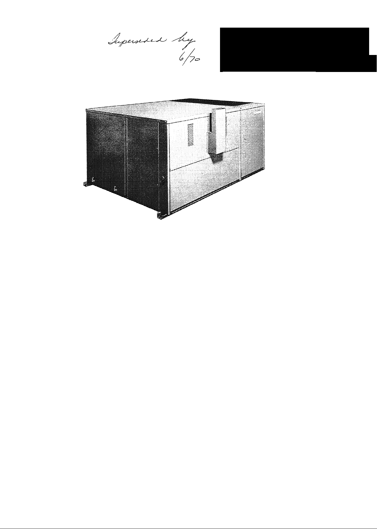
DESCRIPTION
The 48DD012 is a one-piece combination gas heating/
electric cooling unit designed primarily for outdoor rooftop
installation on a factory-supplied curb accessory but can be
installed on grade or conventional steel framework. This
unif combines superior performance with compactness,
versatility of application and ease of installation to supply
year-round air conditioning for commercial and industrial
FEATURES
• Two-Stage Heating and Cooling — Both heating and
cooling stages have 50 percent or 100 percent capacity
ranges of operation This reduces operating costs
• Multiple Choice of Air Flow — Air can be delivered to
the building either thru the bottom of the unit with
separate inlet and outlet air ducts or concentric ducting, or
it can be delivered thru the side of the unit with separate
inlet and outlet air ducts
• Gas Safety Control will shut off the main gas valve in
case of pilot or combustion air failure, or overheating of the
heat exchangers
• Induced Draft Combustion — Unaffected by winds and
drafts Equipped with safety shut-off devices in case of
combustion air failure or blockage
buildings The unit is completely factory assembled,
charged and tested Requires only natural gas, and suitable
electrical and duct connections for hookup. Air can be
supplied to the building either thru bottom of the unit or
thru the side A manually-adjustable outdoor air intake is
provided Condensers are air cooled Low silhouette design
allows units to be easily hidden from street level view
• Automatic Electric Ignition — Pilot flame is auto
matically relighted in case of interruption of power or gas
• Aluminized Heat Exchangers — Resist corrosion and
provide long, quiet, safe, and efficient operation These
heat exchangers have a full ten-year warranty
• Time Guard Circuit* prevents rapid cycling, extends
compressor life When power to unit is interrupted,
compressor cannot restart for five minutes
• Head Pressure Control automatically cycles one of two
condenser fans, permitting cooling operation down to 35 F
ambient temperature
• Other Quality Components — Crankcase heaters and
accumulators to protect the compressor against flooded
starts, filter-driers and sight glasses for moisture control and
visual inspection of refrigerant charge
ACCESSORIES
• 32LM MotormasterTM Head Pressure Control mod
ulates speed of condenser fan motor to maintain saturated
condensing temperature at low outdoor temperatures
• Thermostat Assembly is a two-step heating/two-step
cooling thermostat and a matching switch base Either
automatic or manual changeover is available
• Remote Control Center allows manual control of the
unit from a location remote from the thermostat The
thermostat furnished with the remote control center has no
knobs or switches for manual control
© Carrier Corporation 1970
•Single Feature Sheet Available Form 48DD-1 P
• Roof Curb frames roof opening, is watertight connec
tion between unit and roof Designed so ductwork and roof
flashing may be installed prior to placing the unit
• Modulating Outside Air Control Package (economizer)
can furnish outside air for cooling when outside air
temperature is below 60 F. It can replace operation of the
refrigerant system under these conditions
• LP Conversion Kit used to convert the unit from natural
gas to LP gas usage
• Relief Damper used to relieve positive building pressure
Page 2
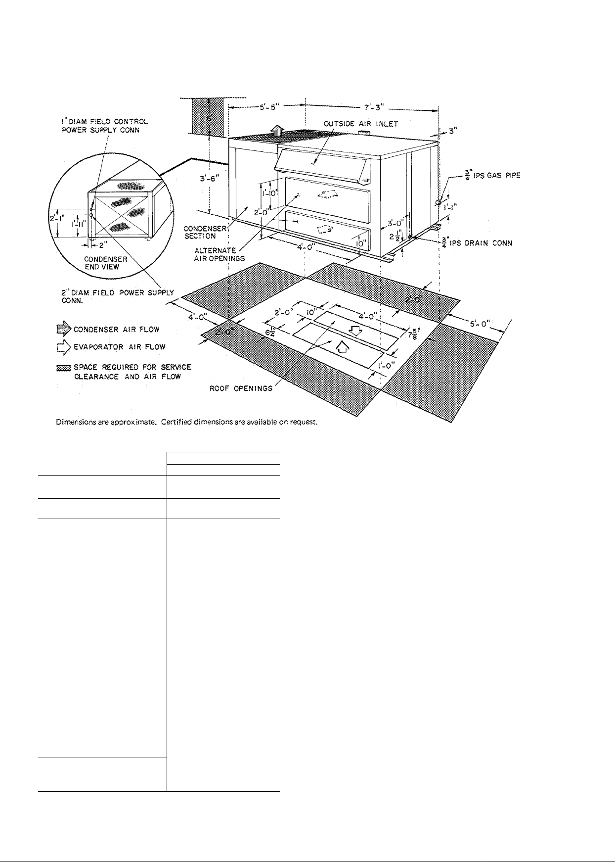
DIMENSIONS
PHYSICAL DATA
UN IT 48 D D
OP ER A TI NG W E IG H T (lb )
RE FR IG E RA N T
Op era ti ng C h arg e (Ib )
CO MP R E SS O R
Cyl in de rs ... Rp m (6 0- H z)
OU TD O O R AI R FA N S
No . .. .D iam (in .)
No m Cf m ea c h. ..to ta l
Mo to r H p ...R p m
CO ND E N SE R C OI L
Ro ws ... F ins /i n.
Tot al Fa c e A re a (s q ft)
IND O OR A IR F A N S
No . .. .S ize (i n. )
No m Cf m
Rp m Ra n ge (S ta n da rd D riv e )
Ma x A ll ow a ble R p m
Bel t T yp e ...L e ng th (i n. )
Mo to r
No . .. .H p. ..R pm
Ma x B ra k e H p
Fra m e
Sha ft D ia m (in .)
Pul le y P it ch D ia m (in .)
EVA P O RA T OR C O IL
Tot al Fa c e A re a (s q ft)
Ro ws ... F ins /i n.
HE AT E XC H A NG E R S
A.G .A . C e rti fie d R ise
No . .. .E lem e nt s (ea c h)
012
169 0
22
9 ea c h S y ste m
(2) Re ci pr oc ati ng H er m eti c
4 ea c h 3 5 00
Pro pe lle r; Di re ct Dr ive
2 2 2
320 0 .6 40 0
1/ 1 1 40 (3 -p ha se )
107 5 (1 -i^ ha s e)
Pla te Fi n
4 1 3
14 0
Cen tr ifu ga l; Be lt Dr ive
2 10x10
400 0
123 0 to 15 40
170 0
A. 4 4
1 3 17 4 5
3 4 5
182 T
iVs
5 6
Pla te Fi n
10 02
3 1 4
Alu mi niz e cd S tee l
45 to 75 F
2 .5
SELECTION PROCEDURE (With Example)
I Determine cooling and heating requirements at design
conditions.
GIVEN;
Required Cooling Capacity (TO
Sensible Heat Capacity (SHC)
Required Heating Capacity
Condenser Entering Air Temp
Indoor Air Temp
Evaporator Air Quantity
Electrical Characteristics
External Static Pressure
II Select unit based on required cooling capacity.
Enter Cooling Capacities table at condenser entering air tempera
ture of 95 F. The 48DD012 at 4000 cfm and 67 F Ewb will
provide a total capacity of 132,000 Btuh and a sensible heat of
96,000 Btuh Calculate SHC correction if required
III Compare the heating capacity of the unit selected with the
design conditions.
Unit 48DD012 provides an input of 275,000 Btuh with a bonnet
capacity of 206,000 Btuh
IV Determine fan speed and brake hp requirements at design
conditions.
Enter Fan Performance table. At 4000 cfm and 8 in wg, the fan
speed is 1 405 rpm and brake hp is 2.34 The table indicates that
standard drive is adequate.
V Select unit that corresponds to available power source.
Refer to Electrical Data table and choose unit as required A
48DD012 230-3-60 is available.
128.000 Btuh
90,000 Btuh
198.000 Btuh
80 F Edb, 67 Ewb
. 95 F
4000 Cfm
230-3-60
8 in. wg
Page 3

48D D 01 2 AR I* - 12 4, 00 0 BT U H
T e mp ( F)
Air En t
Co nd
85
95
100 SHC
105
115
72 *62
TC 147 1
SH C
KW 14.4
TC
SH C
KW 15.6 14.9
TC
KW
TC
SH C 65 3 81 6
KW 16.7 15,8 15.0 16.9 16. 1
TC 121 0 112 1 104 1 123 6
SH C
KW 17.6
134 8 122 5
73 0 87 5 103 5
14.C
128 i
138 9
84.9 101 4
68 7
134 0 124 S 114 8 137 6
84 0 99 6 73 7
67 3
15,3 14.6 16,3 15,7
16.1
130 4 120 7
61 .6
78 4
16.6 15 6
*Rated in accordance with latest ARI Standard 210
Capacities shown (except ARI) are gross capacities
which do not include a deduction for indoor fan
motor heat.
Eva p A
300 0/ .08 ” I ’ 4" c
lyg p A
149 4 139.4
13.4
117 4 141 6
14.2
ms 133
98 2
96 8
BF — Bypass Factor
Ewb — Entering Wet-Bulb
KW — Compressor Motor Power Input
SHC — Sensible Heat Capacity (1000 Btuh)
TC — Total Capacity (1000 Btuh)
ir — C fm / B F
00/ .10 1 5 C
ir - E
12
wkiF
ei
62
129 5
78 8 99 6 120 2
14.2 13.9 14,7 14.6
14.7
132 2 123 8
76 3
96 4 117 6
15.9 15.2 14.6
117 3
128 2
114 8
94 9
15.5 16.5 16,0
114 8 147 2 128 9
123 8
71 8 92 9 89 7
16.9
109 1 126 9
114 8
89 7
109 1 75.9
16 2
68 3
17.7 16.9
PERFORMANCE DATA
COOLING CAPACITIES (60-Hz)
NOTES:
)6o /. 1 2
67 62
144 1
153 0
131 0
87 7 1115 131 0
14.2
146 2 136 8
83 4
16.3 15.6 15,0
142 6 133 4 125 1
82 2 107 0 125 1
108 2
128 6
128 6
15.4
"l21 7
105 0 121 3
79 9
17.1 16.6
18 3
15.9
117 0 114.0
1 14 0
101 5
16 8
17 3
1. Direct interpolation is permissible Do not extrapolate
2 The following formulas may be used:
Mdb fedb ■
f|wb ^ Wet-bulb temperature corresponding to enthalpy of air
h|wb - ■
Where
hewb^ Enthalpy of air entering evaporator coil
SHC is based on 80 F edb temp of air entering evaporator coil
Below 80 F edb, subtract (corr factor x cfm) from SHC
BF
10
20
.30 76
Interpolation is permissible
Correction Factor = 1.08 x (1 - BF) X (edb - 80)
sensible capacity (Btuh)
1 08 X cfm
leaving evaporator coil (h|y^,[з)
total capacity (Btuh)
4.5 X cfm
Entering Air Dry-Bulb Temp (F)
78 I 77 1 76 I 75 [ under 75^"
Correction Factor
97 1 95
86 1 73
2 92 3 89
2 59
1 51 2 27 3 03 3 78
4 86
3 46 4 32
use formula
shown below
HEATING CAPACITIES
UN IT 48 D D0 1 2
Firs t St ag e
Ful l
NOTES
1 Ratings are approved for altitudes to 2,000 ft At altitudes over
2,000 ft, ratings are 4 percent less for each 1,000 ft above sea
level
2 At altitudes up to 2,000 ft, the following formula may be used
to calculate air temp rise:
bonnet capacity
At =
1.08 X air quantity
INP U T
(Bt uh )
37,000
275,000
BO NN E T
(Bt uh )
103.000
206.000
3 At altitudes above 2,000 ft, the following formula may be used:
At
----
--------------------
4 Maximum allowable gas pressure is 14 0 in wg Minimum
allowable gas pressure for full rated input is 5 0 in wg
5 Unit may be field converted for 100 percent LP gas, using
Carrier factory parts Units will maintain A.G A, certification if
conversion is performed as directed and conversion nameplate is
attached to unit adjacent to existing unit nameplate
FAN PERFORMANCE, 48DD012
EXT E RN A L ST A TI C PR E SS U R E ( in . w g )
CF M
300 0
340 0
380 0
400 0
420 0
460 0
- I
J
970 <1030 <1095 \ 1155 1(215 I 1270 I 1320 ! 1380 ! 1425 I 1470 ¡1515 I (560 I (605 i (6.50 i (695
! 1010 i 1075 i 1135 < 1195 i 1245 I 1300 ¡1355 1 1405 I 1450 I 1495 ¡1540 I 1590 i (655 1 1680 I
( 1055 < 1115 ! ((75 I 1230 : 1275 i 1330 i 1385 : 1430 i 1480 i 1520 5 (565 i (6(0 , 1655 \ 1700
1145 ! (200 I 1245 I 1290 I 1345 ! 1400 i 1445 I 1485 I 1530 ! 1575 \ 1620 \ 1665 I
! 1020 I 1080 I 1140 I 1210 \ 1265 1 1325 I 1380 I 1430 I 1475 i 1520 T (560 I 160? I 1650 1 1695 I
.4 r .5 [ .6 [ . 7 1 .8 ] .9 j 1 .0 ^ 1 .1 1 1 .2
Fan R p m
“i 1230 j 1270 I 1315 I 1370 1 1420 i 146.5 > 1510 ' (5.50 i 1595 <1640 <1685 \
bonnet capacity
( 24 X specific weight of air x 60) (air quantity)
1 I
1.5 1 1.6
I
Motor brake horsepower
NOTES:
1 Fan performance has deductions for unit casing losses, wet coil,
heat exchanger, and clean filters
2. Fan motor bhp is based on minimum voltage and 80 F air
across the standard motor
3. All table values printed in italics indicate non standard conditions
Page 4

OPERATING SEQUENCE
ELECTRICAL DATA
Cooling — Power on and thermostat assembly set at "Cool,” "Fan
Auto" and desired temperature.
Step 1 of cooling thermostat energizes outdoor and indoor fans
and Time Guard Circuit Time Guard Circuit delays the start of the
compressor for fifteen seconds.
Step 2 of cooling thermostat operates a second Time Guard
Circuit which delays the start of the second compressor for fifteen
seconds. On compressor shutdown for any reason, Time Guard
Circuit prevents compressor restart for at least five minutes.
Capacity Control — Two-step thermostat operates the compressors
as the cooling load changes.
Heating — Turn power and gas on, and set thermostat assembly at
"Heat," "Fan Auto" and desired temperature.
The induced draft motor is energized whenever unit field power
is on with thermostat set for "Heat" or "Auto." No. 1 glow coil
ignites the no. 1 pilot (a thirty-second delay occurs before glow coil
lights the pilot) Electric pilot shifts to no. 2 glow coil and no. 2
pilot ignites.
After all pilots ignite, unit is ready to heat When step 1 of
heating thermostat closes: the gas valve relay energizes, the main gas
valve opens, the indoor fan relay (IFR 2) closes, the indoor fan
contactor energizes, and the indoor fan motor starts. Burners are
now at 50 percent capacity.
When step 2 of heating thermostat closes and energizes the
second stage of gas valve, the unit operates at full capacity.
When call for heat is satisfied, step 2 of thermostat opens,
de-energizing the second stage of the gas valve.
Unit may cycle between 50 percent and full capacity as step 2
dictates. When step 1 of the thermostat opens, the gas valve relay
shuts off the main gas valve and indoor fan motor.
Automatic Changeover — When system selector switch is set at
"Auto," unit will automatically change from heating to cooling
when the temperature of the conditioned space rises to the cooling
lever setting. When the temperature of the conditioned space falls to
the heating lever setting, the unit will automatically change from
cooling to heating
The thermostat and unit are so connected that the cooling and
heating systems will not operate simultaneously.
Air Circulation — With power on and unit controls set at "Off" and
"Fan," indoor air fan operates' continuously for air circulation.
When controls are set at "Heat" or "Cool" and "Fan," heating or
cooling is provided as required, while indoor fan motor operates
continuously.
TYPICAL WIRING
OPERATING SEQUENCE - ACCESSORY MODULATING
OUTSIDE AIR CONTROL
Cooling Season — Thermostat assembly set at "Cool" and "Fan
Auto." Damper goes to "Vent" when step 1 of cooling thermostat
closes, energizing outdoor and indoor fan motors and the
compressors.
When step 1 is satisfied, outdoor and indoor fan motors and the
compressor shut off, and the outside air damper closes. (Damper
always stays at "Vent" during cooling sequence if fan switch is at
"Fan," and night switch is closed.)
Intermediate Season — Same as for cooling season, except that as
step 1 of thermostat closes and indoor fan motor starts, compressor
and outdoor fan motor remain off if outside air temperature is
below outdoor air thermostat setting. If outside and return air
temperature rises above or drops below mixed air thermostat
setting, the outside air damper will reposition to maintain the
thermostat setting. Damper will move to closed position when
cooling step 1 is satisified Damper will move to "Vent" position
when fan switch is at "Fan."
The outside air damper will close when the night switch is
opened (night position), or whenever the indoor fan shuts down.
Heating Season — Damper always stays at "Vent" while fan motor is
operating. Outside air damper closes when night switch opens.
C
■ Compressor Contactor LP
■ Cooling Compensators LS
cc
Ccw '
•Counterclockwise MAT.
CH
■ Crankcase Heater NS
CR
■ Control Relay
CS
■ Centrifugal Switch OAT.
Cw
■ Clockwise OFC
DM
■ Damper Motor OI
FDM
■ Forced Draft Motor Pii
FDR
■ Forced Draft Relay R
GC
■Glow Coil RES
GV
■ Gas Valve TB
GVR
■ Gas Valve Relay TC
HA
■ Heating Anticipator TDR
HPCT
■ Head Pressure TH
• Control Thermostat TM
HR
■ Holding Relay TRANS
■ Indoor Fan Contactor
IFC
IFR
■ Indoor Fan Relay
IP
■ Internal Protector
LEGEND
_______
_______
- Low Pressure Switch
- Limit Switch
- Mixed Air Thermostat
- Night Switch
(Field supplied)
- Outside Air Thermostat
- Outdoor Fan Contactor
- Overload
■ Pilot
- Relay
- Resistance Wire
- Terminal Block
- Thermostat, Cooling
- Time Delay Relay
- Thermostat, Heating
• Timer Motor
- Transformer
Factory Wiring
Field Wiring
Page 5

ELECTRICAL DATA (Cont)
ELECTRICAL DATA (60-Hz)
VOLTAGE
V/PH
208/3 220-180
230/3
460/3
RANGE
254-198 70 0
506-414
WSA ICF
79.6
33 9 69
FLA — Full Load Amps
FU — Fuse (max allowable amps)
ICF —Max Instantaneous Current Flow during start-up is the sum of
compressor LRA plus the FLA of all other motors in the unit
UNIT
152
137
COMPR* IFM OFM
FU FLA LRA FLA (ea)
10.6
100 27.60
90
23.80
45 11 85 50
1 10
100
9.2 3 2
4.6
3.2
1 2
IFM — Indoor Fan Motor
LRA — Locked Rotor Amps
OFM — Outdoor Fan Motor
WSA — Wire Sizing Amps per NEC equals 1 25 X FLA of the largest
motor plus the sum of the FLA of all other motors in
the unit.
*Unit has two compressor motors; values are for each.
TYPICAL PIPING AND WIRING
ROOFTOP INSTALLATION WITH SEPARATE SUPPLY AND RETURN DUCTWORK
ADDITIONAL UNIT AI R FLOW ARRANGEMENTS
CONCENTRIC DUCTING THRU THE BOTTOM
APPLICATION
THRU The side
[^AIRFLOW
note ; Accessory economizer cannot be used with this air flow arrangement.
Page 6

APPLICATION (Coni)
LOW OUTDOOR TEMPERATURE COOLING OPERATION
It is not necessary to use the refrigeration system for cooling
when the outdoor air temperature is below 60 F. The use of
outdoor air will handle the cooling load. This is a more economical
method of cooling in cold weather
One condenser fan motor is cycled off when the outdoor air
temp drops to 55 F. This allows operation down to 35 F outdoor
CONTROLS (Protective Devices)
temperature The other condenser fan motor is suitable for use with
the 32LM MotormasterTM Head Pressure Control at outdoor
temperatures below 35 F (see Accessories). Operation with this
control requires winter start provisions (low pressure switch
recalibration): and may require field-fabricated condenser air
baffles.
• Limit Switches shut off gas supply if excessive air temperatures
should develop; limit discharge air temperature to 175 F when unit
is used for heating.
• Current Overloads with Automatic Reset are current sensitive
and temperature compensated; will open the control circuit if
compressor current is excessive.
• Internal Thermostat with Automatic Reset Is embedded in
compressor windings; de-energizes the control circuit if extreme
temperatures should develop due to excessive suction gas tempera
ture or motor overloading
• High Pressure Relief Device protects unit from excessive com
pressor discharge pressures and prevents overheating.
GUIDE SPECIFICATIONS
Unit shall be of the single-package type, combination air-to-air
cooling and gas-fired heating.
Total Net Cooling Capacity of the system shall be 124,000 Btuh
or greater, and sensible capacity shall be 94,900 Btuh or greater, at
conditions of: 4500 cfm evaporator air entering unit at 67 F
wet-bulb, 80 F dry-bulb and condenser entering air temperature of
95 F dry-bulb Compressor power input shall not exceed 15.5 kw.
Heating Capacity of the system shall be 206,000 Btuh or greater,
with gas input of 275,000 Btuh
Casing shall be constructed of galvanneal steel, bonderized and
coated with baked enamel
Compressor — The unit shall contain two hermetic compressors
with suitable vibration isolators. Crankcase heaters shall be supplied
with the unit
Coils shall be constructed with aluminum plate fins mechanically
bonded to copper tubes
Fans and Motors - The indoor fan shall be of the forward-
curved centrifugal type, belt driven by a 3 hp motor The condenser
• Circuit Breaker provides short circuit protection for controls.
• Low Pressurestat with Automatic Reset de-energizes the control
circuit if refrigerant pressure drops below setting; provides pro
tection from loss of refrigerant charge.
• Inherent Fan Motor Protection with Automatic Reset opens
power circuit if temperatures or current become excessive on
3-phase motors (single-phase motors are temperature sensitive only).
• Fusible Plug located on the accumulator, protects against
excessive pressures or temperatures in the refrigerant system.
• Centrifugal Switch located in the induced air fan motor will
de-energize the gas valve in case of combustion air failure.
section shall have two propeller fans, each directly driven by a 1/2
hp motor.
Heat Exchanger shall be constructed of corrosion resistant
aluminized steel. Burners shall be of the Bunsen (aerated) slotted
port type: readily accessible, and covered by a 10-year warranty.
Safety Controls — Cooling section shall be protected by: fusible
plug, low pressurestat, compressor motor overloads, and a timing
device which will prohibit the compressor motor from being
subjected to starting current more than once every five minutes.
Heating Controls shall consist of an automatic gas valve, pilot,
automatic ignition system, limit switches and a centrifugal switch.
Dimensions — The unit casing shall have width of not more than
65 in., length of not more than 87 in , and height of not more than
42 inches
Accessories — Roof Curb, Modulating Outdoor Air Control,
Remote Control Center, Two-Stage Heat-Cool Automatic Change
over Thermostat, Relief Damper, LP Conversion Kit, and 32LM
MotormasterTM Head Pressure Control.
Manufacturer reserves the right to change any product specifications without notice.
CARRIER AIR CONDITIONING COMPANY • SYRACUSE, NEW YORK
Tab 6
Form48DD-1P New
Printed in U.S.A.
2-70
Codes B and MS
Catalog No. 524-811
 Loading...