

Carrier 38YRA030 SERIES340, 38YRA036 SERIES300, 38YRA036 SERIES330, 38YRA060 SERIES300, 38YRA048 SERIES340 Installation Guide
...
h_cAll NG & COOUNG
12 SEER Split-System Heat Pump
Visit www.camer.com
Installation and Start-Up Instructions
NOTE: Read the entire instruction manual before starting the
installation.
This symbol --->indicates a change since the last issue.
SAFETY CONSIDERATIONS
Improper installation, adjustment, alteration, service, maintenance,
or use can cause explosion, fire, electrical shock, or other
conditions which may cause death, personal injury, or property
damage. Consult a qualified installer, service agency, or your
distributor or branch for information or assistance. The qualified
installer or agency must use factory-authorized kits or accessories
when modifying this product. Refer to the individual instructions
packaged with the kits or accessories when installing.
Follow all safety codes. Wear safety glasses, protective clothing,
and work gloves. Use quenching cloth for brazing operations.
Have fire extinguisher available. Read these insta_ctions thor-
oughly and follow all warnings or cautions included in literature
and attached to the unit. Consult local building codes and National
Electrical Code (NEC) for special requirements.
Recognize safety information. This is the safety-alert symbol/_.
When you see this symbol on the unit and in instructions or
manuals, be alert to the potential for personal injury.
Understand the signal words DANGER, WARNING, and CAU-
TION. These words are used with the safety-alert symbol. DAN-
GER identifies the most serious hazards which will result in severe
personal injury or death. WARNING signifies hazards which
could result in personal injury or death. CAUTION is used to
identify unsafe practices which would result in minor personal
injury or product and property damage. NOTE is used to highlight
suggestions that will result in enhanced installation, reliability, or
operation.
Ir!]l i,','l'-_:K'II_[_]
Before installing, modifying, or servicing system, main elec-
trical disconnect switch must be in the OFF position. There
may be more than 1 disconnect switch. Lock out and tag
switch with a suitable warning label. Electrical shock can
cause personal injury or death.
INSTALLATION RECOMMENDATIONS
NOTE: In some cases noise in the living area hasbeen traced to
gas pulsations from improper installation of equipment.
1. Locate unit away from windows, patios, decks, etc. where unit
operation sounds may disturb customer.
2. Ensure that vapor and liquid tube diameters are appropriate to
capacity' of unit.
3. Run refrigerant tubes as directly as possible by avoiding
unnecessary taa'ns and bends.
4. Leave some slack between structure and unit to absorb
vibration.
5. When passing refrigerant tubes through the wall. seal opening
with RTV or other pliable silicon-basod caulk. (See Fig. 2.)
38YRA
A98516
Fig. 1--Model 38YRA
6. Avoid direct tubing contact with water pipes, duct work, floor
joists, wall studs, floors, and walls.
7. Do not suspend refrigerant tubing from joists and studs with a
rigid wire or strap which comes in direct contact with tubing.
(See Fig. 2.)
8. Ensure that tubing insulation is pliable and completely sur-
rounds vapor tube.
9. When necessary, use hanger straps which are 1 in. wide and
conform to shape of tubing insulation. (See Fig. 2.)
10. Isolate hanger straps from insulation by using metal sleeves
bent to conform to shape of insulation.
When outdoor unit is connected to factory-approved indoor unit,
outdoor unit contains system refrigerant charge for operation with
indoor unit of the same size when connected by 15 ft of
field-supplied or factory accessory tubing. For proper unit opera-
tion, check refrigerant charge using charging information located
on control box cover.
IMPORTANT: Maximum liquid-line size is 318-in. O.D. for all
residential applications including long line.
IMPORTANT: Always install a liqnid-line filter drier. Refer to
Product Data Digest for appropriate part number. Obtain filter
drier from service parts or your distributor or branch.
INSTALLATION
Step l_heck Equipment and Job Site
UNPACK UNIT
Move to final location. Remove carton taking care not to damage
unit.
Manufacturer reserves the right to discontinue, or change at any time, specifications ot designs without notice and without incurring obligations.
PC 101 Catalog No. 533-80021 Pnnted in U.S.A. Form 38YRA-4SI Pg 1 02-02 Replaces: 38YRA3SI
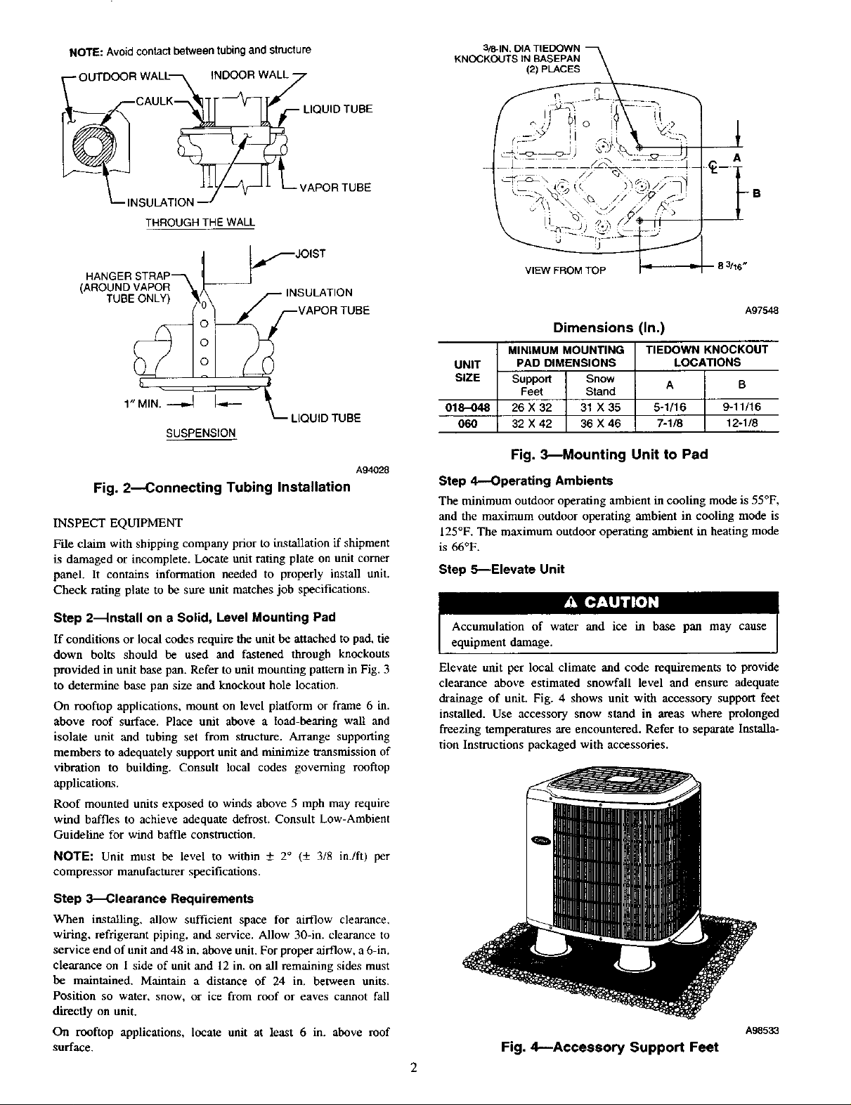
NOTE:Avoidcontactbetweentubingandstructure
OUTOOORWALL ,NOOORWAy
CAULK_ LIQUIDTUBE
3/8-1N. [_
KNOCKOUTS IN BASEPAN
(2) PLACES
SULATION .--i
_" _ _r_ L-- VAPOR TUBE
THROUGHTHEWALL
HANGERSTRAP_
(AROUNDVAPOR
__I_ JOIST
-- INSULATION
VAPOR TUBE
TUBE_ iONLY) !_(
L LIQUID TUBE
SUSPENSION
A94028
Fig. 2--Connecting Tubing Installation
INSPECT EQUIPMENT
F'de claim with shipping company prior to installation if shipment
is damaged or incomplete. Locate unit rating plate on unit corner
panel. It contains information needed to properly install unit.
Check rating plate to be sure unit matches job specifications.
Step 2--Install on a Solid, Level Mounting Pad
If conditionsor local codes require the unit be attachedto pad, tie
down belts should be used and fastened through knockouts
provided in unit basepan. Refer to unit mountingpatternin Fig.3
to determine base pan size and knockout hole location.
On rooftop applications, mount on level platform or frame 6 in.
above roof surface. Place unit above a toad-bearing wall and
isolate unit and tubing set from structure. Arrange supporting
members to adequately support unit and minimize transmission of
vibration to building. Consult local codes governing rooftop
applications.
Roof mounted units exposed to winds above 5 mph may require
wind baffles to achieve adequate defrost. Consult Low-Ambient
Guideline for wind baffle construction.
NOTE: Unit must be level to within _+ 2 ° (-+ 318 in./ft! per
compressor manufacturer specifications.
VIEW FROM TOP
A97548
Dimensions (In.)
MINIMUM MOUNTING
UNIT LOCATIONS
SIZE
PAD DIMENSIONS
Support Snow
Feet Stand
018-048 5-1/16 9-11/16
060 7-1/8 12-1/8
26 X 32 31 X 35
32 X 42 36 X 46
TIEDOWN KNOCKOUT
A B
Fig. 3--Mounting Unit to Pad
Step 4,--Operating Ambients
The minimum outdoor operating ambient in cooling mode is 55°F,
and the maximum outdoor operating ambient in cooling mode is
125°F. The maximum outdoor operating ambient in heating mode
is 66°F.
Step S--Elevate Unit
ry_l[_7_t j/[,,] ,'1
Accumulation of water and ice in base pan may cause
equipment damage.
Elevate unit per local climate and code requirements to provide
clearance above estimated snowfall level and ensure adequate
drainage of unit. Fig. 4 shows unit with accessory support feet
installed. Use accessory snow stand in areas where prolonged
freezing temperatures are encountered. Refer to separate Installa-
tion Instructions packaged with accessories.
Step 3----Clearance Requirements
When installing, allow sufficient space for airflow clearance,
wiring, refrigerant piping, and service. Allow 30-in. clearance to
service end of unit and 48 in. above unit. For proper airflow, a 6-in.
clearance on i side of unit and 12 in. on all remaining sides must
be maintained. Maintain a distance of 24 in. between units.
Position so water, snow, or ice from roof or eaves cannot fall
directly on unit.
On rooftop applications, locate unit at least 6 in. above roof
surface.
A_5_
Fig. 4--Accessory Support Feet

BULB
U L'ZEB
__________ SENSING
_" I1"_'--- THERMOSTATIC
EXPANSION
O'CLOCK
2
SENSING BULB
SUCTION
8 O'CLOCK 4 O'CLOCK
7/sIN. OD & SMALLER LARGER THAN 7/s IN. OD
A88382
Fig. 5_Typical TXV Installation
Step 6--Remove Indoor AccuRate_ Piston and Install
TXV
For proper unit operation and reliability, units must be
installed with field-supplied hard shutoff TXV. Do not install
with evaporator coils having capillary tube metering devices
or pistons.
For TXV kit part number and charging instructions, refer to TXV
label in outdoor unit.
FURNACE COILS
If TXV installation is required, remove existing AccuRater from
indoor coil. Refer to Fig. 5 and 6 and install TXV kit as follows:
1. Install suction tube adapter.
2. Install liquid flare-to-sweat adapter.
3. Connect external equalizer tube to fitting on suction tube
adapter.
4. Position sensing bulb on horizontal portion of suction tube
adapter. Secure using supplied hardware.
5. Insulate bulb after installation. (See Fig. 6.)
6, Leak check all connections.
A81032
Fig. 6--Positioning of Sensing Bulb
DEFROST
THERMOSTAT
A97517
Fig. 7--Defrost Thermostat Location
Step 9_lnstall Liquid-Line Solenoid Valve
(LSV)---Optional
Heating efficiency (HSPF) can be improved by the addition of a
LSV. Refer to presale literature for raring enhancement. Install
LSV per Installation Instructions included with accessory kit.
NOTE: To enhance heating HSPF, flow arrow must point toward
outdoor coil.
Step 10--Make Piping Connections
FAN COILS
If indoor unit (fan coil) comes factory equipped with a bi-fiow
hard shutoff TXV, no TXV change is required.
Refer to TXV kit Installation Instructions for details on TXV
installation.
Step 7--Check Outdoor AccuRater_D Piston
Check outdoor unit piston. Remove retainer on liquid service valve
and check piston size with matching number listed on outdoor unit
radng plate_
Step 8_Check Defrost Thermostat
Check defrost thermostat to ensure it is properly located and
securely attached. There is a liquid header with a brass distributor
and feeder tube going into outdoor coil. At the end of 1 of the
feeder tubes, there is a 3/8-in. O.D. stub tube approximately 3 in.
long. (See Fig. 7.) The defrost thermostat should be located on stub
tube. Note that there is only 1 stub robe used with liquid header,
and on most units it is the bottom circuit.
including solenoid valves,

Table 1--Refrigerant Connections and Recommended Liquid and Vapor Tube Diameters (In.)
UNIT
SIZE
018
024
030
036
042, 048
060
NOTES:
1. Tube diameters are for lengths up to 50 ft. For tubing lengths greater than 50 ft, consult Residential Split System Long-Liee Application Guideline.
2. Do not apply ¢apillan/tube indoor coils to these units.
Connection Diameter
LIQUID VAPOR VAPOR(LONG LINE)
3/8
3/8
3/8
3/8
3/8
3/8
Tube Diameter
3/8
3/8
3/8
3/8
3/8
3/8
Connection Diameter
5/8
3/4
3/4
7/8
7/8
7/8
Tube Diameter
5/8
3/4
3/4
7/8
7/8
1-1/8
ConnectionDiameter
5/8
3/4
3/4
7/8
7/8
7/8
Tube Diameter
3/4
3/4
7/8
7/8
1-1/8
1-1/8
¥__[,.Y..M].i [,] "_I
To prevent damage to unit or service valves observe the
following:
• Use a brazing shield.
• Wrap service valves with wet cloth or use a heat sink
material.
Outdoor units may be connected to indoor section using accessory
tubing package or field-supplied refrigerant grade tubing of correct
size and condition. For tubing requirements beyond 50 fi, substan-
tial capacity and performance losses can occur. Following the
recommendations in the Residential Split System Long-Line
Application Guideline will reduce these losses. Refer to Table 1
for field tubing equivalent line length. Refer to Table 2 for
accessory requirements.
For buried-line applications greater than 36 in., consult your local
distributor.
If refrigerant tubes or indoor coil are exposed to atmosphere, they
must be evacuated to 500 microns to eliminate contamination and
moisture in the system.
OUTDOOR UNIT CONNECTED TO FACTORY-APPROVED
INDOOR UNIT
Outdoor unit contains correct system refrigerant charge for opera-
tion with indoor unit of same size when connected by 15 ft of
field-supplied or factory-accessory tubing. Check refrigerant
charge for maximum efficiency.
REFRIGERANT TUBING
Connect tubing to fittings on outdoor unit vapor and liquid service
valves. (See Table 1.) Use refrigerant grade tubing.
SWEAT CONNECTION
To avoid valve damage while brazing, service valves must be
wrapped in a beat-sinking material such as a wet cloth.
Remove plastic retainer holding outdoor piston in liquid service
valve and connect sweat/flare adapter provided to valve. (See Fig.
8.) Connect refrigerant tubing to fittings on outdoor unit vapor and
liquid service valves. Service valves are closed from factory and
ready for brazing. After wrapping service valve with a wet cloth.
tubing set can be brazed to service valve using either silver bearing
or non-silver bearing brazing material. Consult local code require-
ments. Refrigerant tubing and indoor coil are now ready for leak
testing. This check should include all field and factory joints.
IMPORTANT: Check to be certain factory tubing on both indoor
and outdoor unit has not shifted during shipment. Ensure tubes are
not rubbing against each other or any sheet metal. Pay close
attention to feeder tubes, making sure wire ties on feeder tubes are
secure and tight.
Table 2--Accessory Usage
REQUIRED FOR
ACCESSORY LONG-LINE
Crankcase Heater Yes Yes
Evaporator Freeze Thermostat Yes No
Accumulator No No
Compressor Start Assist
Capacitor and Relay Yes Yes
MntorMseter_ Control,
Low-Ambient Pressure Switch
Liquid-Line Solenoid Valve See Long-Line
*F . . , ....
RO_tubinghne setsbetween50 and 175 ft, referto ResidentialSplitSystemLonQ-Iine ApplmationGuideline.
equ=redfor Low-AmbientController(fullmodulationfeature) and MntorMasterControlonly.
Ball Bearing Fan Motor Yes_: No
or Yes No
Wind Baffle See Low-Ambient Instructions No
Support Feet Recommended No
or No Application
Hard Shutoff TXV Guideline
LOW-AMBIENT
APPLICATIONS
(BELOW 55°F) (OVER 50 FT)
REQUIRED FOR
APPLICATIONS*
 Loading...