

Carrier 38TMA User Manual
HEATING & COOLING
instaiiation and Start-Up instructions
NOTE: Read this entire instruction before beginning installation.
SAFETY CONSIDERATIONS
Improper installation, adjustment, alteration, service, maintenance,
or use can cause explosion, fire, electrical shock or other condi
tions which may cause personal injury or property damage.
Consult a qualified installer, service agency, or your distributor or
branch for information or assistance. The qualified installer or
agency must use factory-authorized kits or accessories when
modifying this product. Refer to the individual instructions pack
aged with the kits or accessories when installing.
Follow all safety codes. Wear safety glasses and work gloves. Use
quenching cloth for brazing operations. Have fire extinguisher
available. Read these instmctions thoroughly and follow all
warning or cautions attached to the unit. Consult local building
codes and National Electrical Code (NEC) for special require
ments.
It is important to recognize safety information. This is the
safety-alert symbol ^ . When you see this symbol on the unit and
in instructions or manuals, be alert to the potential for personal
injury.
Understand the signal word— DANGER, WARNING, or CAU
TION. These words are used with the safety-alert symbol. DAN
GER identifies the most serious hazards which will result in severe
personal injury or death. WARNING signifies hazards that could
result in personal injury or death. CAUTION is used to identify
unsafe practices, which would result in minor personal injury or
product and property damage.
A WARNING
Before installing or servicing system, always turn off main
power to system. There may be more than one disconnect
switch. Turn off accessory heater power if applicable. Elec
trical shock can cause personal injury or death.
INSTALLATION
Step 1—Check Equipment and Jobsite
UNPACK UNIT
Move to final location. Remove carton taking care not to damage
unit.
INSPECT EQUIPMENT
File claim with shipping company prior to installation if shipment
is damaged or incomplete. Locate unit rating plate on unit service
panel. (See Fig. 2.) It contains information needed to properly
install unit. Check rating plate to be sure unit matches job
specifications.
38TMA
Air Conditioning Unit
A88160
Fig. 1—Model 38TMA
Step 2—Install on a Solid, Level Mounting Pad
The minimum mounting pad dimensions are 26 in. x 32 in.
(660.4mm X 812.8mm). If conditions or local codes require the
unit be attached to pad, tiedown bolts should be used and fastened
through knockouts provided in unit base pan. Refer to unit
mounting pattern in Fig. 2 to determine base pan size and knockout
hole location.
When installing, allow sufficient space for airflow clearance,
wiring, refrigerant piping and service. Allow 30-in. (762mm)
clearance to service end of unit and 48 in. (1219mm) above unit.
For proper airflow, a 6-in. (152mm) clearance on one side of unit
and 12 in. (305mm) on all remaining sides must be maintained.
Maintain a distance of 24 in. (610mm) between air conditioners.
Position so snow or ice from roof or eaves cannot fall directly on
unit.
On rooftop applications, locate unit 6 in. (152mm) above roof
surface. Where possible, place unit above a loadbearing wall.
Arrange supporting members to adequately support unit and
minimize transmission of vibration to building. Consult local
codes governing rooftop applications.
Step 3—Replace Indoor AccuRater® Piston, if Required
Check indoor coil piston to see if it matches the required piston
shown on unit rating plate. If it does not match, replace indoor coil
piston with piston shipped with this unit. The piston shipped with
outdoor unit is correct for any approved indoor coil combination.
Manufacturer reserves the right to discontinue, or change at any time, specifications or designs without notice and without incurring obiigations.
Book 1 4
Tab 3a 2a
PC 101 Catalog No. 563-812 Printed in U.S.A. Form 38TMA-1SI
pgi
12-91 Replaces: New
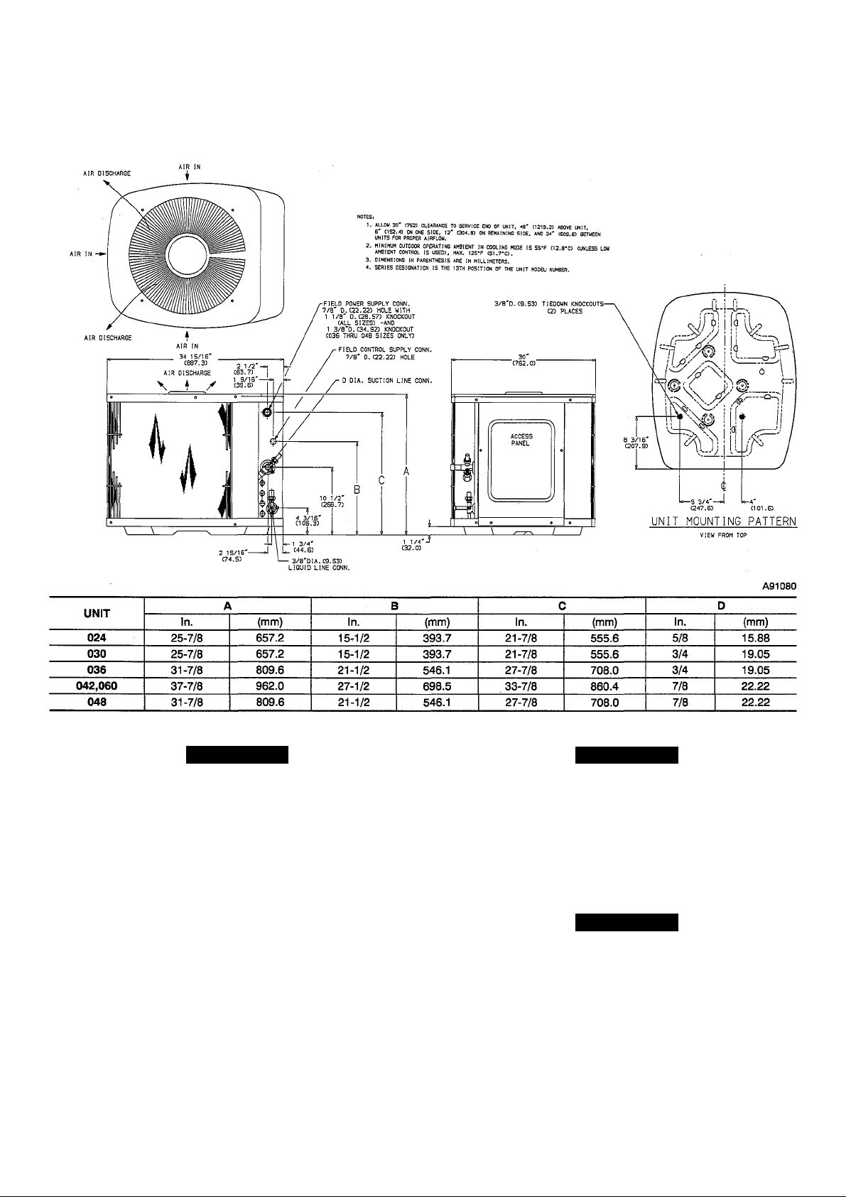
Fig. 2—Unit Reference Drawing
A CAUTION A CAUTION
If unit is to be installed on system with a thermostatic
expansion valve (TXV), removal of the indoor coU piston is
required.
Step 4—Make Piping Connections
Outdoor units may be connected to indoor sections using accessory
tubing package or field-supplied tubing of refrigerant grade,
correct size, and condition. The liquid- and vapor-tube diameters
can be determined by using Table 1. For tubing requirements
beyond 50 ft (15.24m), obtain information from your local
distributor.
If required, install solenoid valve in liquid line to achieve desired
rating. (See Fig. 3.)
DO NOT BURY MORE THAN 36 IN. (914mm) OF RE
FRIGERANT TUBING IN GROUND. If any section of
tubing is buried, there must be a 6- in.(152mm) vertical rise
to the valve connections on the outdoor unit. K more than the
recommended length is buried, refrigerant may migrate to
cooler buried section during extended periods of unit shut
down, causing refrigerant slugging and possible compressor
damage at start-up.
A CAUTION
For systems installed with a liquid-hue solenoid valve,
solenoid valve must be energized during evacuation and
purging for effective evacuation.
If either refrigerant tubing or indoor coil is exposed to atmospheric
conditions for longer than 5 minutes, it must be evacuated to 1000
microns to eliminate contamination and moisture in the system.
 Loading...