

Page 1
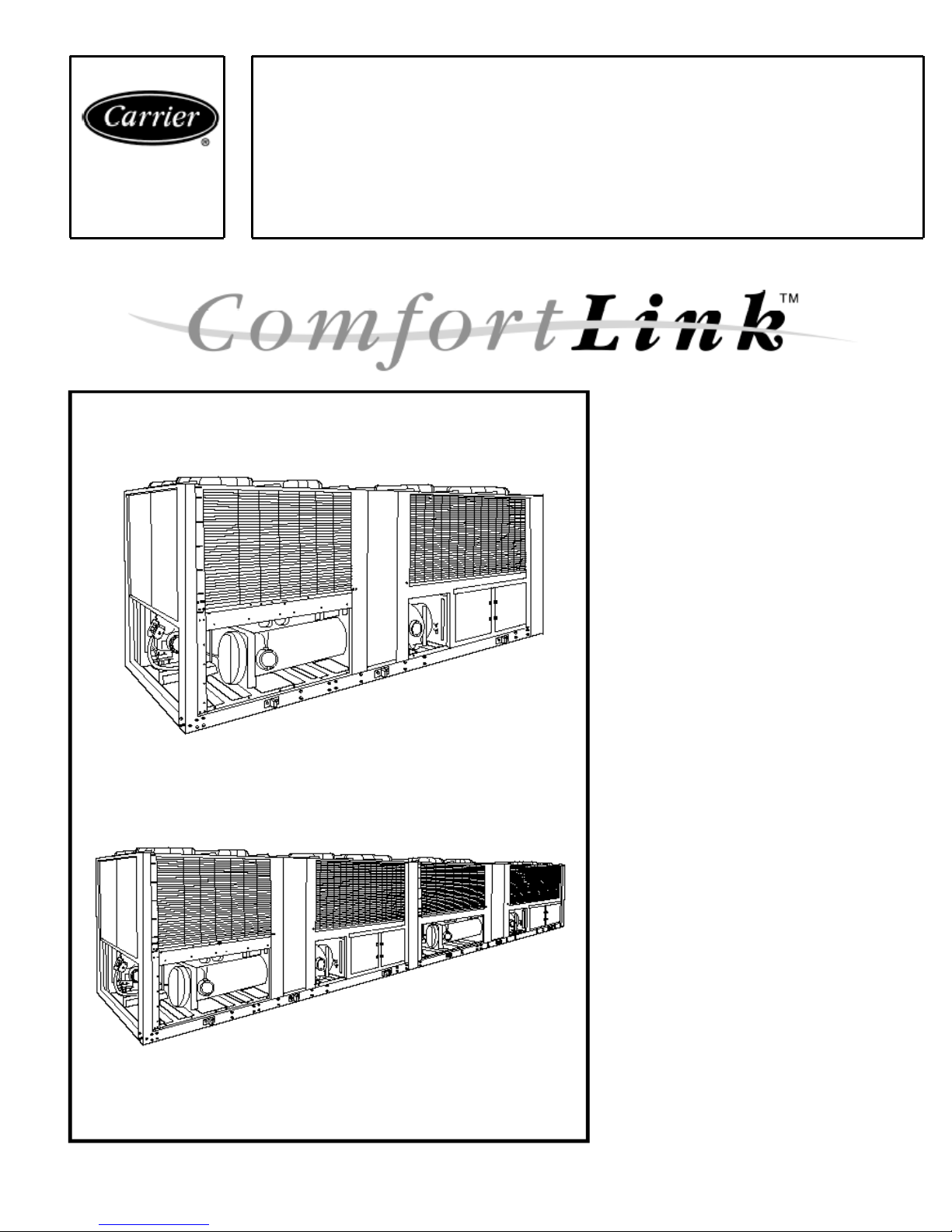
Product
Data
30GTN,GTR,GBN,GBR
Air-Cooled Reciprocating
Liquid Chillers
with ComfortLink™ Controls
50 Hz
Nominal Capacities: 50 to 400 Tons
127 to 1445 kW
Features/Benefits
ComfortLink control
Your link to a world of simple and easy to use
air-cooled chillers that offer outstanding
performance and value. The 30GTN,GTR,
GBN,GBR liquid chillers employ more than the
latest advanced microprocessor controls, they
utilize an expandable platform that grows as
your needs change. From stand-alone operation
to remotely monitored and operated multichiller plants, ComfortLink controls can keep
you plugged in.
ComfortLink controls are fully
communicating, and are cable ready for
connection to a Carrier Comfort Network
(CCN). Occupancy scheduling, temperature
and pressure read-outs, and the ComfortLink
scrolling marquee clear language display
compliment the standard features, linking you
to a world of carefree comfort. The
30GTN,GTR,GBN,GBR chillers are built on
the legendary performance of the Carrier model
30G Flotronic™ chiller and share many of the
same time-proven features and technologies
providing easy operation, quick installation and
start-ups that save you money!
Superior temperature control equals
potential for greater productivity
Whether in the classroom, on the production
floor, or in the office, ComfortLink controls can
help you to adapt to changing weather and
business conditions. Accurate temperature
control provided by the Carrier ComfortLink
system helps to maintain higher levels of indoor
air quality, thermal comfort, and productivity
space.
While many air-cooled chillers use only
leaving fluid temperature control, the
30GTN,GTR,GBN,GBR chillers utilize leaving
fluid temperature control with a standard
entering fluid temperature compensation.
1
Page 2

This Carrier exclusive provides smar
t
r
f
f
r
r
r
r
f
t
f
control and intelligent machine capacity
staging. Unlike many chillers, Carrier
model 30GTN,GTR,GBN,GBR chillers
do not require constant fluid flow. The
ability to operate with variable flow also
allows building owners to realize even
greater overall system energy savings in
the chilled water pumping system of up
to 85%, and not just at the chiller.
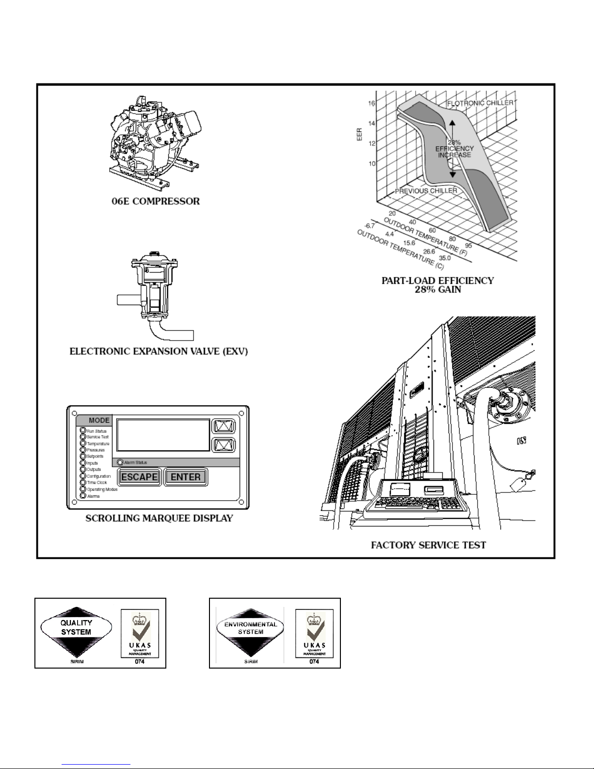
Full and part load efficiency
advantage
The 30GTN,GTR,GBN,GBR chillers
with ComfortLink control offe
outstanding efficiencies (EER [Energy
Efficiency Ratio], COP [coefficient o
performance], and IPLV [integrated part
load value]) in both full (up to 10.0
EER) and part load operation (IPLVs up
to 14.7). Increased part load efficiency is
provided by dual independent
refrigeration circuits, suction cutof
unloading, and return fluid temperature
compensation.
The fully integrated ComfortLink
control system maintains efficient
control over the compressors, unloaders,
expansion valves, and condenser fans to
optimize performance as conditions
change. The Carrier exclusive longstroke
electronic expansion valve (EXV)
operates at reduced condensing
pressures, thereby allowing the control to
operate the fans down to lower outdoo
temperatures. By utilizing valve position
information, the control maintains the
highest possible evaporator pressure and
minimizes the excessive superheat that
conventional thermal expansion valve
(TXV) systems require. Wider operating
ranges equal increased efficiencies and
lower installed costs.
Building design flexibility
Design and consulting engineers will
appreciate the broad selection of sizes
and wide operating range offered by the
30GTN,GTR,GBN,GBR chillers. With
built-in dual chiller control, imaginative
large tonnage systems can be easily
engineered and controlled with smaller,
easier to handle modules. Modula
design allows engineers to consider side
by side, offset, or angled placement to fit
the awkward spaces that the architect
sometimes leaves for mechanical
systems. Or, in the case of planned
expansion, additional cooling can be
brought on-line and controlled from the
same system.
In some places facility managers
may find that the cash flow provided by
building up large air cooled multi-chiller
plants can easily offset any efficiency
losses when compared to large wate
cooled centrifugal type chilled wate
plants.
Quality and reliability
To assure long life and quality
performance, every chiller is factory run
tested. Individual components are also
tested at many levels to assure that only
the best parts make it into
30GTN,GTR,GBN,GBR chillers. Long
life and reliability are also a function o
design. While some manufacturers like
to talk about moving parts, Carrier’s
engineers recognized the potential
dangers to chiller systems caused by
problems in the power distribution
system. Low voltage and phase
imbalances are but a few of the
conditions that can hurt the compressor’s
motor.
Model 30G chillers were one of the firs
to offer ground current sensing to
prevent compressor motor burn-out that
would contaminate the system and
potentially threaten the life of future
replacement compressors. The 06E semihermetic compressors are built for
performance and have proven
themselves in commercial refrigeration
equipment worldwide.
With tens of thousands of chillers
operating in all corners of the world,
end-users count on the reliability o
Carrier 30G chillers. The Carrier
International Sdn. Bhd. Malaysia plant
is an ISO 9001 registered facility as are
many of Carrier’s other component and
assembly plants throughout the world.
Features
• Simple and easy to use ComfortLink
communicating controls.
• Wide operating envelope from –28
to 52 C (–20 to 125 F).
• Accurate temperature control with
return fluid compensation.
• Value added features built-in; dual
chiller control, reset from return.
• Superior full and part-load efficiency.
• Precise multiple-step capacity.
• Low noise operation (quieter than
many screw chillers).
• Dual independent refrigerant
circuits.
• Factory run tested.
• Wide range of sizes available from
stock.
• History of proven performance and
reliability.
Table of contents
Page
Features/Benefits ..............................................................................................1-3
Model Number Nomenclature..............................................................................4
Physical Data..................................................................................................5-10
Base Unit Dimensions .................................................................................. 11-17
Application Data...........................................................................................18-23
Selection Procedure.......................................................................................24,25
Performance Data.........................................................................................25-27
Electrical Data ...............................................................................................28,29
Controls .........................................................................................................30,31
Typical Piping and Wiring ............................................................................32,33
Guide Specifications......................................................................................34,35
2
Page 3
Features/Benefits (cont)
Quality Assurance
MS ISO 9001 REG. NO. AR 0239 MS ISO 14001 CERT. NO. C003001129
3
Page 4
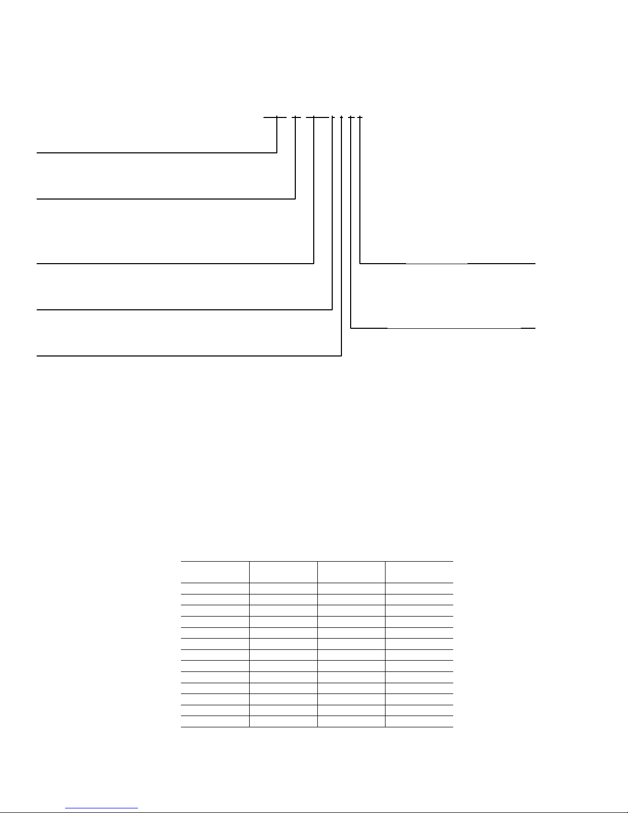
Model number nomenclature
30GT N 100 - - C 9
30GT/GB – Air-Cooled Liquid Chiller
Compressor Start
N – Across-The-Line Start with ComfortLink™ Controls
R – Part-Wind Start with ComfortLink™ Controls
Unit Sizes*
050 080 110 200 400
060 090 150 300
070 100 175 350
Module Designation (300-400 Unit Sizes Only)*
A
B
Not Used
V-Ph-Hz
9 – 400-3-50
Condenser Coil Options
- – Copper Tube, Aluminum Fins
C – Copper Tube, Copper Fins
*Refer to Unit Sizes and Modular Combinations below.
UNIT SIZES AND MODULAR COMBINATIONS
UNIT
30GTN,GBN
050 50 — —
060 60 — —
070 70 — —
080 80 — —
090 90 — —
100 100 — —
110 110 — —
150 150 — —
175 175 — —
200 200 — —
300 300 150 150
350 350 175 175
400 400 200 200
NOMINAL
TONS
SECTION A
UNIT 30GBN
SECTION B
UNIT 30GBN
4
Page 5
5
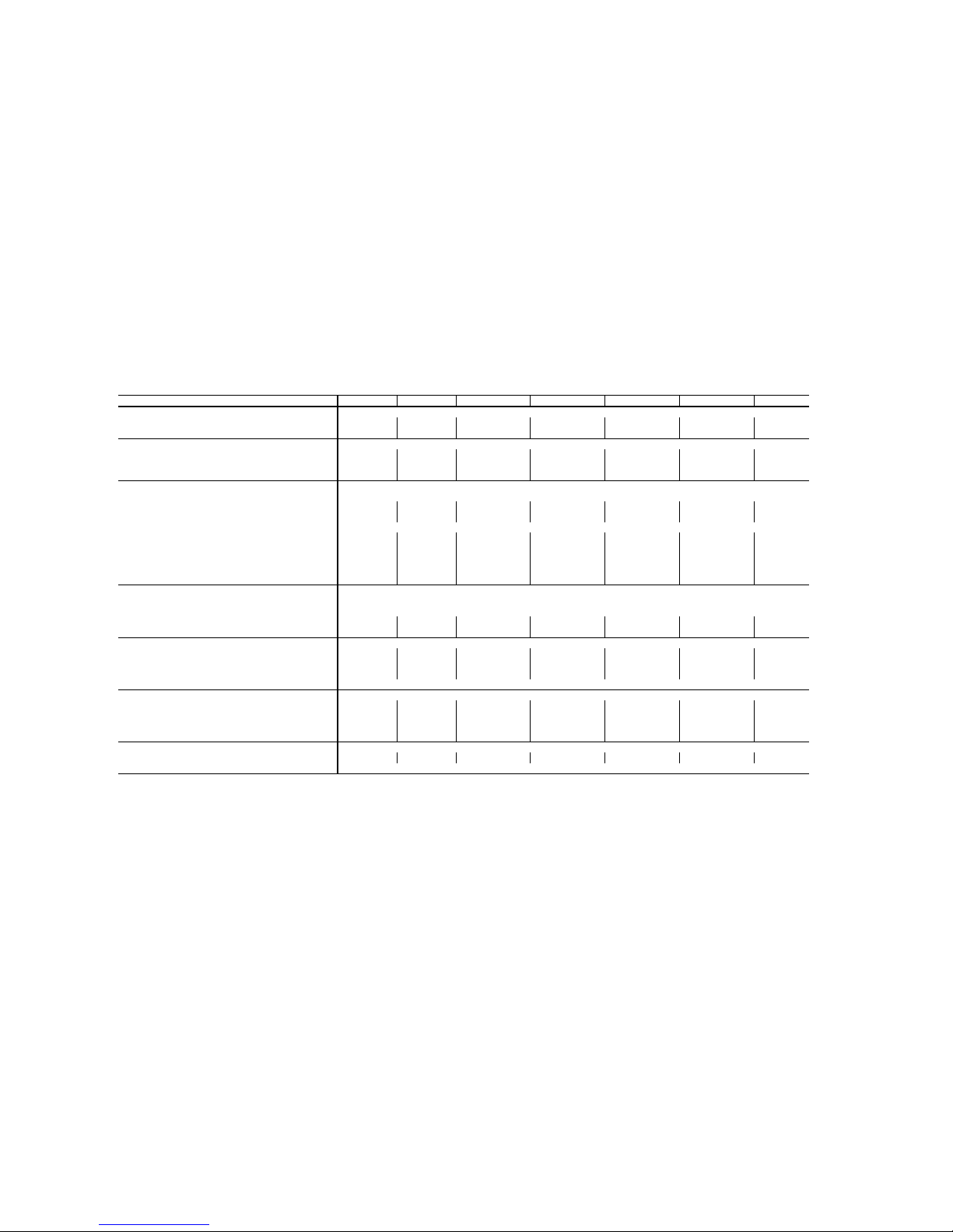
Physical Data – English
LEGEND
Cu-Al – Copper Tubing, Aluminium Fins Condenser Coil
Cu-Cu – Copper Tubing, Copper Fins Condenser Coil
OD – Outside Diameter
30GTN, GTR UNIT SIZE 050 060 070 080 090 100 110
APPROX OPERATING WEIGHT (lb)
Cu-Al 3916 4780 5453 6720 7135 8710 8840
Cu-Cu 4329 5197 6081 7445 7860 9660 9790
REFRIGERANT TYPE R-22
Charge (lb)
Ckt A 48 52 71 78 78 98 98
Ckt B 60 54 69 78 78 105 105
COMPRESSORS Reciprocating, Semi-Hermetic
Speed (rpm) 1450
06E (Qty) Ckt A (1) 275 (1) 299 (1) 265, (1) 265 (1) 265, (1) 299 (1) 265, (1) 299 (1) 265, (1) 299 (2) 299
(Qty) Ckt B (1) 299 (1) 299 (1) 299 (1) 299 (1) 265, (1) 275 (1) 265, (1) 299 (2) 299
Oil Charge (Compressor/pt) 265/19.0, 275/19.0, 299/19.0
No. Capacity Control Steps 4444888
Capacity (%)
Ckt A 43.3 50.0 58.0 62.0 54.0 50.0 50.0
Ckt B 56.7 50.0 42.0 38.0 46.0 50.0 50.0
Minimum Capacity Step (%) 28.8 33.3 19.3 16.0 14.0 13.0 17.0
CONDENSER FANS Propeller, Direct Drive
Fan Speed (rpm) 950
No. Blades…Dia.(in.) 6…30
No. Fans…Hp/kW (each) 4…2.5/1.85 6…2.5/1.85 6…2.5/1.85 6..2.5/1.85 6…2.5/1.85 8…2.5/1.85 8..2.5/1.85
Total Airflow (cfm) 34,000 52,000 51,000 57,000 57,000 76,000 76,000
CONDENSER COILS 3/8-in. OD Vertical and Horizontal, Plate Fin, Enhanced Copper Tubing
Fins/in. 17 17 17 17 17 17 17
No. Rows (Ckt A or B) 3233333
Face Area, Ckt A and B Total (sq ft) 80.5 116.7 116.7 128.3 128.3 168.0 168.0
Max Working Pressure Refrigerant (psig) 450
COOLER One…Direct Expansion, Shell and Tube
No. Refrigerant Circuits 2222222
Net Water Volume, includes nozzles (gal.) 13.5 18.0 18.0 24.5 24.5 30.3 30.3
Max Working Pressure Refrigerant Side (psig) 278 278 278 278 278 278 278
Max Working Pressure Fluid Side (psig) 300 300 300 300 300 300 300
FLUID CONNECTIONS (in.) Flat Face Flange
Inlet and Outlet 3444455
Drain (NPT) 3/4
Page 6
6
Physical Data – English (cont)
LEGEND
Cu-Al – Copper Tubing, Aluminium Fins Condenser Coil
Cu-Cu – Copper Tubing, Copper Fins Condenser Coil
OD – Outside Diameter
30GBN,GBR UNIT SIZE 150 175 200
APPROX OPERATING WEIGHT (lb)
Cu-Al 14,100 14,600 15,100
Cu-Cu 15,030 15,530 16,030
REFRIGERANT TYPE R-22
Charge (lb)
Ckt A 230 230 230
Ckt B 230 230 230
COMPRESSORS Reciprocating, Semi-Hermetic
Speed (rpm) 1450
06E (Qty) Ckt A (1) 275, (2) 299 (1) 275, (2) 299 (1) 275, (3) 299
(Qty) Ckt B (1) 275, (2) 299 (1) 275, (3) 299 (1) 275, (3) 299
Oil Charge (Compressor/pt) 265/19.0, 275/19.0, 299/19.0
No. Capacity Control Steps 678
Capacity (%)
Ckt A 50 57 50
Ckt B 50 43 50
Minimum Capacity Step (%) 17 14 13
CONDENSER FANS Propeller, Direct Drive
Fan Speed (rpm) 950
No. Blades…Dia.(in.) 6…30
No. Fans…Hp/kW (each) 12…2.5/1.85
Total Airflow (cfm) 120,000
CONDENSER COILS 1/2-in. OD Vertical and Horizontal, Plate Fin, Enhanced Copper Tubing
Fins/in. 13.5 13.5 13.5
No. Rows (Ckt A or B) 444
Face Area, Ckt A and B Total (sq ft) 121.0 121.0 121.0
Max Working Pressure Refrigerant (psig) 450
COOLER One…Direct Expansion, Shell and Tube
No. Refrigerant Circuits 222
Net Water Volume, includes nozzles (gal.) 60.2 60.2 60.2
Max Working Pressure Refrigerant Side (psig) 235 235 235
Max Working Pressure Fluid Side (psig) 250 250 250
FLUID CONNECTIONS (in.) Flat Face Flange
Inlet and Outlet 666
Drain (NPT) 3/4
Page 7
7
Physical Data – English (cont)
LEGEND
Cu-Al – Copper Tubing, Aluminium Fins Condenser Coil
Cu-Cu – Copper Tubing, Copper Fins Condenser Coil
OD – Outside Diameter
30GBN,GBR UNIT SIZE 300 350 400
SYSTEM MODULES A B Total A B Total A B Total
APPROX OPERATING WEIGHT (lb)
Cu-Al 14,100 14,100 28,200 14,600 14,600 29,200 15,100 15,100 30,200
Cu-Cu 15,030 15,030 30,060 15,530 15,530 31,060 16,030 16,030 32,060
REFRIGERANT TYPE R-22
Charge (lb)
Ckt A 230 230 - 230 230 - 230 230 -
Ckt B 230 230 - 230 230 - 230 230 -
COMPRESSORS Reciprocating, Semi-Hermetic
Speed (rpm) 1450
06E (Qty) Ckt A (1) 275, (2) 299 (1) 275, (2) 299 - (1) 275, (2) 299 (1) 275, (2) 299 - (1) 275, (3) 299 (1) 275, (3) 299 -
(Qty) Ckt B (1) 275, (2) 299 (1) 275, (2) 299 - (1) 275, (3) 299 (1) 275, (3) 299 - (1) 275, (3) 299 (1) 275, (3) 299 -
Oil Charge (Compressor/pt) 265/19.0, 275/19.0, 299/19.0
No. Capacity Control Steps 66-77-88-
Capacity (%)
Ckt A 50 50 - 57 57 - 50 50 -
Ckt B 50 50 - 43 43 - 50 50 -
Minimum Capacity Step (%) 17 17 - 14 14 - 13 13 -
CONDENSER FANS Propeller, Direct Drive
Fan Speed (rpm) 950 950 - 950 950 - 950 950 -
No. Blades…Dia.(in.) 6…30 6…30 - 6…30 6…30 - 6…30 6…30 -
No. Fans…Hp/kW (each) 12…2.5/1.85 12…2.5/1.85 24…2.5/1.85 12…2.5/1.85 12…2.5/1.85 24…2.5/1.85 12…2.5/1.85 12…2.5/1.85 24…2.5/1.85
Total Airflow (cfm) 120,000 120,000 240,000 120,000 120,000 240,000 120,000 120,000 240,000
CONDENSER COILS 1/2-in. OD Vertical and Horizontal, Plate Fin, Enhanced Copper Tubing
Fins/in. 13.5 13.5 - 13.5 13.5 - 13.5 13.5 -
No. Rows (Ckt A or B) 44-44-44-
Face Area, Ckt A and B Total (sq ft) 121.0 121.0 242.0 121.0 121.0 242.0 121.0 121.0 242.0
Max Working Pressure Refrigerant (psig) 450 450 450 450 450 450
COOLER One…Direct Expansion, Shell and Tube
No. Refrigerant Circuits 224224224
Net Water Volume, includes nozzles (gal.) 60.2 60.2 120.4 60.2 60.2 120.4 60.2 60.2 120.4
Max Working Pressure Refrigerant Side (psig) 235 235 - 235 235 - 235 235 -
Max Working Pressure Fluid Side (psig) 150 150 - 150 150 - 150 150 -
FLUID CONNECTIONS (in.) Flat Face Flange
Inlet and Outlet 66-66-66-
Drain (NPT) 3/4 3/4 - 3/4 3/4 - 3/4 3/4 -
Page 8
8
Physical Data – SI
LEGEND
Cu-Al – Copper Tubing, Aluminium Fins Condenser Coil
Cu-Cu – Copper Tubing, Copper Fins Condenser Coil
OD – Outside Diameter
30GTN,GTR UNIT SIZE 050 060 070 080 090 100 110
APPROX OPERATING WEIGHT (kg)
Cu-Al 1776 2168 2473 3055 3243 3960 4018
Cu-Cu 1972 2357 2758 3384 3573 4390 4450
REFRIGERANT TYPE R-22
Charge (kg)
Ckt A 21.8 23.6 32.2 35.4 35.4 44.5 44.5
Ckt B 27.2 24.5 31.3 35.4 35.4 44.5 47.7
COMPRESSORS Reciprocating, Semi-Hermetic
Speed (r/s) 24.2
06E (Qty) Ckt A (1) 275 (1) 299 (1) 265, (1) 265 (1) 265, (1) 299 (1) 265, (1) 299 (1) 265, (1) 299 (2) 299
(Qty) Ckt B (1) 299 (1) 299 (1) 299 (1) 299 (1) 265, (1) 275 (1) 265, (1) 299 (2) 299
Oil Charge (Compressor/L) 265/9.0, 275/9.0, 299/9.0
No. Capacity Control Steps 4444888
Capacity (%)
Ckt A 43.3 50.0 58.0 62.0 54.0 50.0 50.0
Ckt B 56.7 50.0 42.0 38.0 46.0 50.0 50.0
Minimum Capacity Step (%) 28.8 33.3 19.3 16.0 14.0 13.0 17.0
CONDENSER FANS Propeller, Direct Drive
Fan Speed (r/s) 15.8
No. Blades…Dia.(mm) 6…762
No. Fans…kW (each) 4…1.85 6…1.85 6…1.85 6…1.85 6…1.85 8…1.85 8..1.85
Total Airflow (L/s) 16,045 25,540 24,068 26,898 26,898 35,864 35,864
CONDENSER COILS 9.53 mm OD Vertical and Horizontal, Plate Fin, Enhanced Copper Tubing
Fins/m. 669 669 669 669 669 669 669
No. Rows (Ckt A or B) 3233333
Face Area, Ckt A and B Total (sq m) 7.48 10.84 10.84 11.92 11.92 15.61 15.61
Max Working Pressure Refrigerant (kPa) 3103
COOLER One…Direct Expansion, Shell and Tube
No. Refrigerant Circuits 2222222
Net Water Volume, includes nozzles (L) 51.1 68.1 68.1 92.7 92.7 114.7 114.7
Max Working Pressure Refrigerant Side (kPa) 1916 1916 1916 1916 1916 1916 1916
Max Working Pressure Fluid Side (kPa) 2068 2068 2068 2068 2068 2068 2068
FLUID CONNECTIONS (in.) Flat Face Flange
Inlet and Outlet 3444455
Drain (NPT) 3/4
Page 9
9
Physical Data – SI (cont)
LEGEND
Cu-Al – Copper Tubing, Aluminium Fins Condenser Coil
Cu-Cu – Copper Tubing, Copper Fins Condenser Coil
OD – Outside Diameter
30GBN,GBR UNIT SIZE 150 175 200
APPROX OPERATING WEIGHT (kg)
Cu-Al 6396 6625 6850
Cu-Cu 6816 7045 7270
REFRIGERANT TYPE R-22
Charge (kg)
Ckt A 104.3 104.3 104.3
Ckt B 104.3 104.3 104.3
COMPRESSORS Reciprocating, Semi-Hermetic
Speed (r/s) 24.2
06E (Qty) Ckt A (1) 275, (2) 299 (1) 275, (2) 299 (1) 275, (3) 299
(Qty) Ckt B (1) 275, (2) 299 (1) 275, (3) 299 (1) 275, (3) 299
Oil Charge (Compressor/L) 265/9.0, 275/9.0, 299/9.0
No. Capacity Control Steps 678
Capacity (%)
Ckt A 50 57 50
Ckt B 50 43 50
Minimum Capacity Step (%) 17 14 13
CONDENSER FANS Propeller, Direct Drive
Fan Speed (r/s) 15.8
No. Blades…Dia.(mm) 6…762
No. Fans…kW (each) 12…1.85
Total Airflow (L/s) 56,628
CONDENSER COILS 12.7 mm OD Vertical and Horizontal, Plate Fin, Enhanced Copper Tubing
Fins/m 531 531 531
No. Rows (Ckt A or B) 444
Face Area, Ckt A and B Total (sq m) 11.24 11.24 11.24
Max Working Pressure Refrigerant (kPa) 3103
COOLER One…Direct Expansion, Shell and Tube
No. Refrigerant Circuits 222
Net Water Volume, includes nozzles (L) 227.9 227.9 227.9
Max Working Pressure Refrigerant Side (kPa) 1620 1620 1620
Max Working Pressure Fluid Side (kPa) 1034 1034 1034
FLUID CONNECTIONS (in.) Flat Face Flange
Inlet and Outlet 666
Drain (NPT) 3/4
Page 10
10
Physical Data – SI (cont)
LEGEND
Cu-Al – Copper Tubing, Aluminium Fins Condenser Coil
Cu-Cu – Copper Tubing, Copper Fins Condenser Coil
OD – Outside Diameter
30GBN,GBR UNIT SIZE 300 350 400
SYSTEM MODULES A B Total A B Total A B Total
APPROX OPERATING WEIGHT (kg)
Cu-Al 6396 6396 12792 6625 6625 13250 6850 6850 13700
Cu-Cu 6816 6816 13632 7045 7045 14090 7270 7270 14540
REFRIGERANT TYPE R-22
Charge (kg)
Ckt A 104.3 104.3 - 104.3 104.3 - 104.3 104.3 -
Ckt B 104.3 104.3 - 104.3 104.3 - 104.3 104.3 -
COMPRESSORS Reciprocating, Semi-Hermetic
Speed (r/s) 24.2
06E (Qty) Ckt A (1) 275, (2) 299 (1) 275, (2) 299 - (1) 275, (3) 299 (1) 275, (2) 299 - (1) 275, (3) 299 (1) 275, (3) 299 -
(Qty) Ckt B (1) 275, (2) 299 (1) 275, (2) 299 - (1) 275, (2) 299 (1) 275, (3) 299 - (1) 275, (3) 299 (1) 275, (3) 299 -
Oil Charge (Compressor/L) 265/9.0, 275/9.0, 299/9.0
No. Capacity Control Steps 66-77-88-
Capacity (%)
Ckt A 50 50 - 57 57 - 50 50 -
Ckt B 50 50 - 43 43 - 50 50 -
Minimum Capacity Step (%) 17 17 - 14 14 - 13 13 -
CONDENSER FANS Propeller, Direct Drive
Fan Speed (r/s) 15.8 15.8 - 15.8 15.8 - 15.8 15.8 -
No. Blades…Dia.(mm) 6…762 6…762 - 6…762 6…762 - 6…762 6…762 -
No. Fans…kW (each) 12…1.85 12…1.85 24…1.85 12…1.85 12…1.85 24…1.85 12…1.85 12…1.85 24…1.85
Total Airflow (L/s) 56,628 56,628 113,256 56,628 56,628 113,256 56,628 56,628 113,256
CONDENSER COILS 12.7 mm OD Vertical and Horizontal, Plate Fin, Enhanced Copper Tubing
Fins/m 531 531 - 531 531 - 531 531 -
No. Rows (Ckt A or B) 44-44-44-
Face Area, Ckt A and B Total (sq m) 11.24 11.24 22.48 11.24 11.24 22.48 11.24 11.24 22.48
Max Working Pressure Refrigerant (kPa) 3103 3103 3103 3103 3103 3103
COOLER One…Direct Expansion, Shell and Tube
No. Refrigerant Circuits 224224224
Net Water Volume, includes nozzles (L.) 227.9 227.9 455.8 227.9 227.9 455.8 227.9 227.9 455.8
Max Working Pressure Refrigerant Side (kPa) 1620 1620 - 1620 1620 - 1620 1620 -
Max Working Pressure Fluid Side (kPa) 1034 1034 - 1034 1034 - 1034 1034 -
FLUID CONNECTIONS (in.) Flat Face Flange
Inlet and Outlet 66-66-66-
Drain (NPT) 3/4 3/4 - 3/4 3/4 - 3/4 3/4 -
Page 11
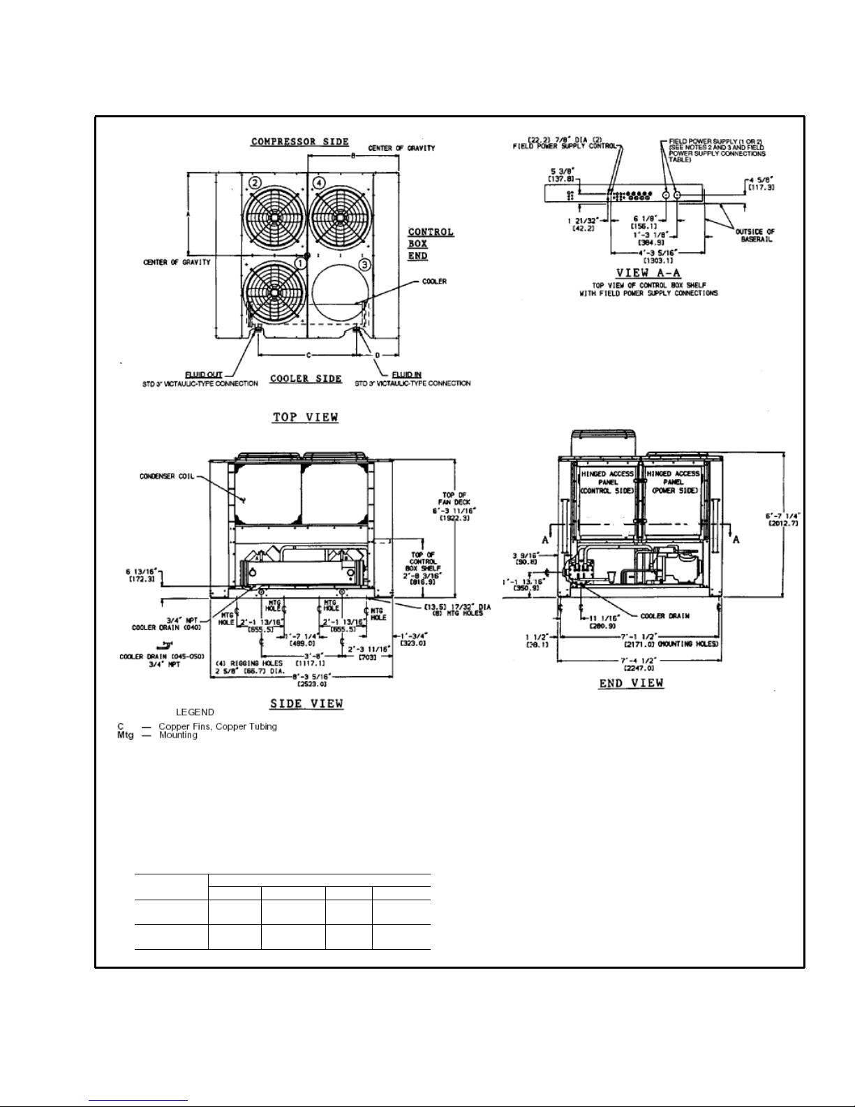
11
Base unit dimensions — 30GTN,GTR050
NOTES:
1. Unit must have clearances for airflow as follows:
TOP – Do not restrict in any way.
ENDS – [1524] 5 ft
SIDES – [1829] 6 ft
2. Mounting holes may be used to mount unit to concrete pad. They are not
recommended for spring isolator location.
3. If spring isolators are used, a perimeter support channel between the unit
and isolators is recommended.
4. Dimensions in [ ] are millimeters.
UNIT DIMENSIONS
30GTN,GTR “A” “B” “C” “D”
050
3’-5 7/8”
[1064]
3’-11”
[1194]
5’-5 ½”
[1663]
1’-5 3/16”
[436.6]
050C
3’-6”
[1067]
3’-11 3/16”
[1199]
5’-5 ½”
[1663]
1’-5 3/16”
[436.6]
Page 12
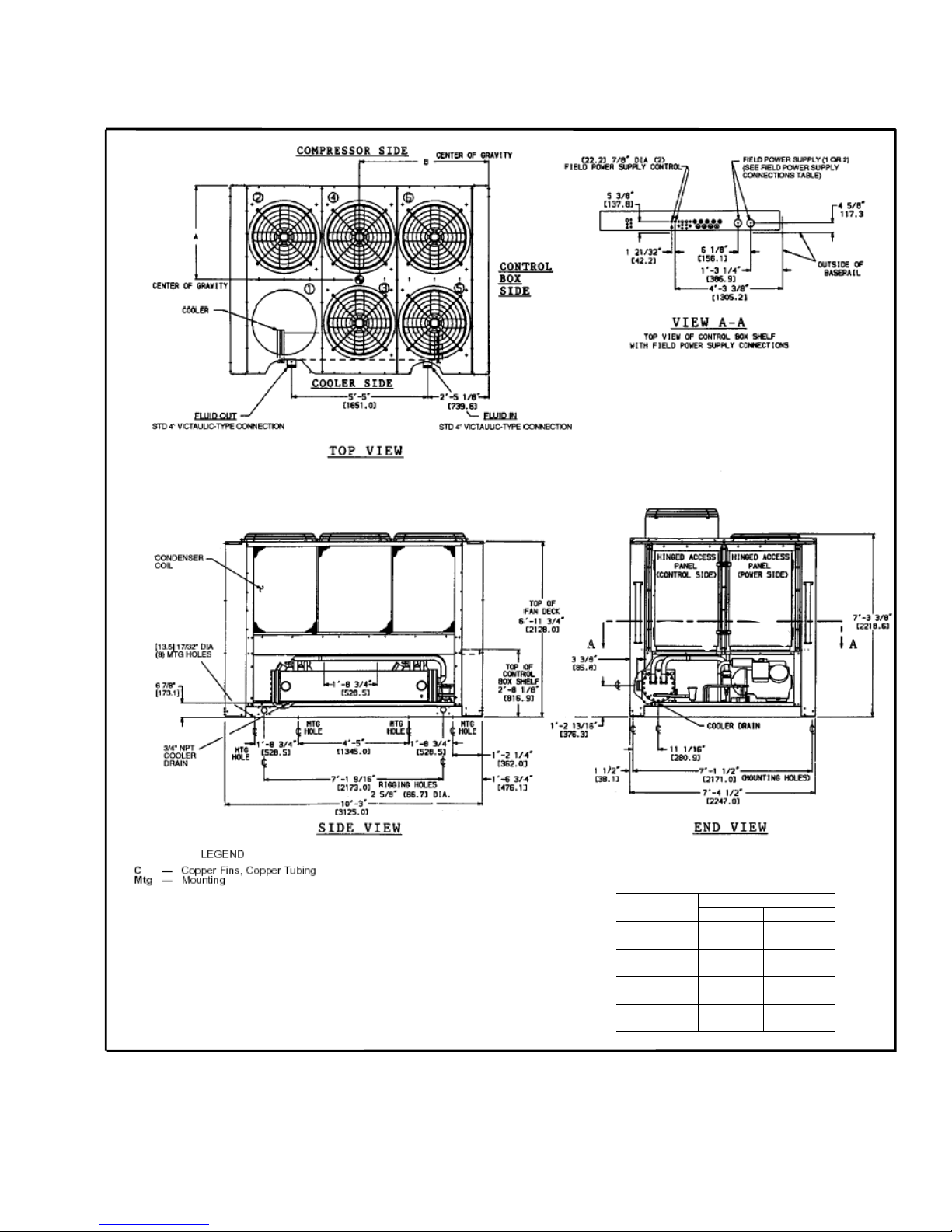
12
Base unit dimensions — 30GTN,GTR060,070
NOTES
UNIT DIMENSIONS
30GTN,GTR “A” “B”
060
3’-6 7/8”
[1090]
4’-10 5/16”
[1481]
060C
3’-7”
[1092]
4’-10 9/16”
[1488]
070
3’-6”
[1067]
4’-10 ½”
[1486]
070C
3’-6 3/16”
[1072]
4’-10 7/8”
[1496]
1. Unit must have clearances for airflow as follows:
TOP – Do not restrict in any way.
ENDS – [1524] 5 ft
SIDES – [1829] 6 ft
2. Mounting holes may be used to mount unit to concrete pad. They are not
recommended for spring isolator location.
3. If spring isolators are used, a perimeter support channel between the unit
and isolators is recommended.
4. Dimensions in [ ] are millimeters.
Page 13
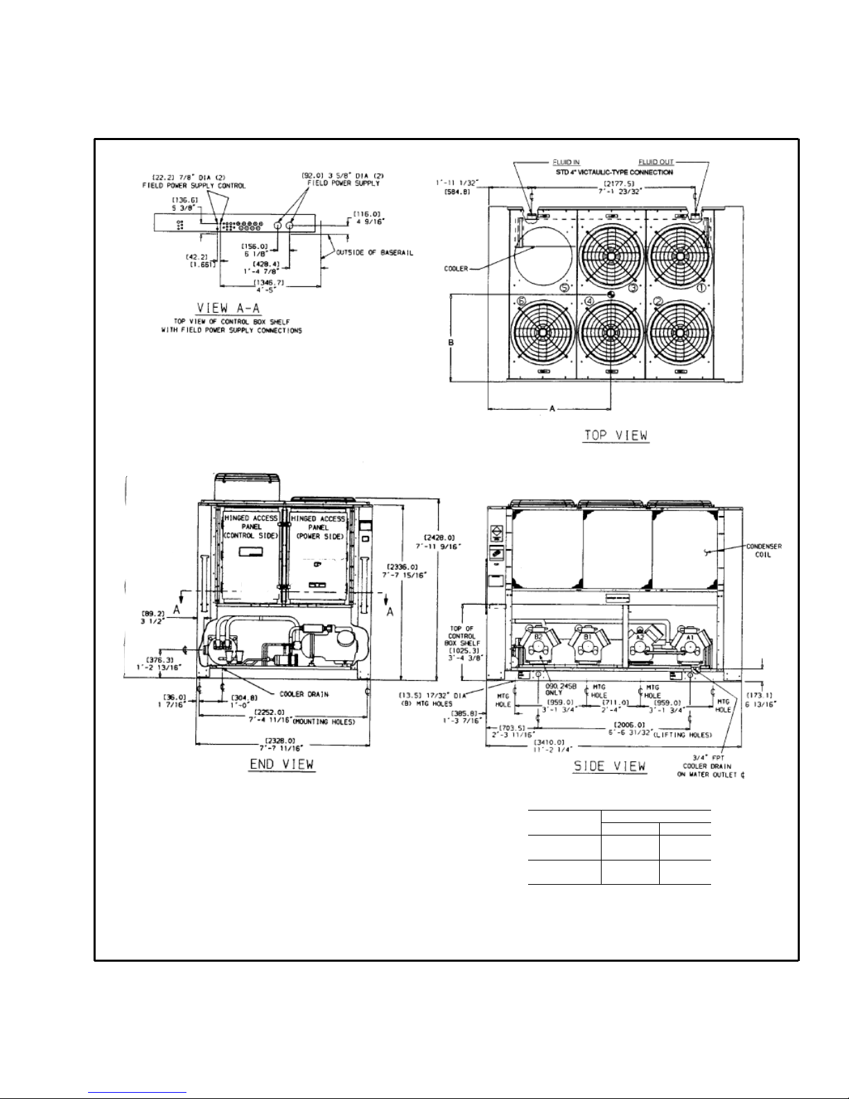
13
Base unit dimensions — 30GTN,GTR080,090
UNIT DIMENSIONS
30GTN,GTR “A” “B”
080
5’-9 5/8”
[1769]
3’-6”
[1067]
090
5’-7 5/16”
[1710]
3’-2 3/4”
[984]
NOTES:
1. Unit must have clearances for airflow as follows:
TOP – Do not restrict in any way.
ENDS – [1524] 5 ft
SIDES – [1829] 6 ft
2. Mounting holes may be used to mount unit to concrete pad.
They are not
recommended for spring isolator location.
3. If spring isolators are used, a perimeter support channel
between the unit
and isolators is recommended.
4. Dimensions in [ ] are millimeters.
Page 14
14
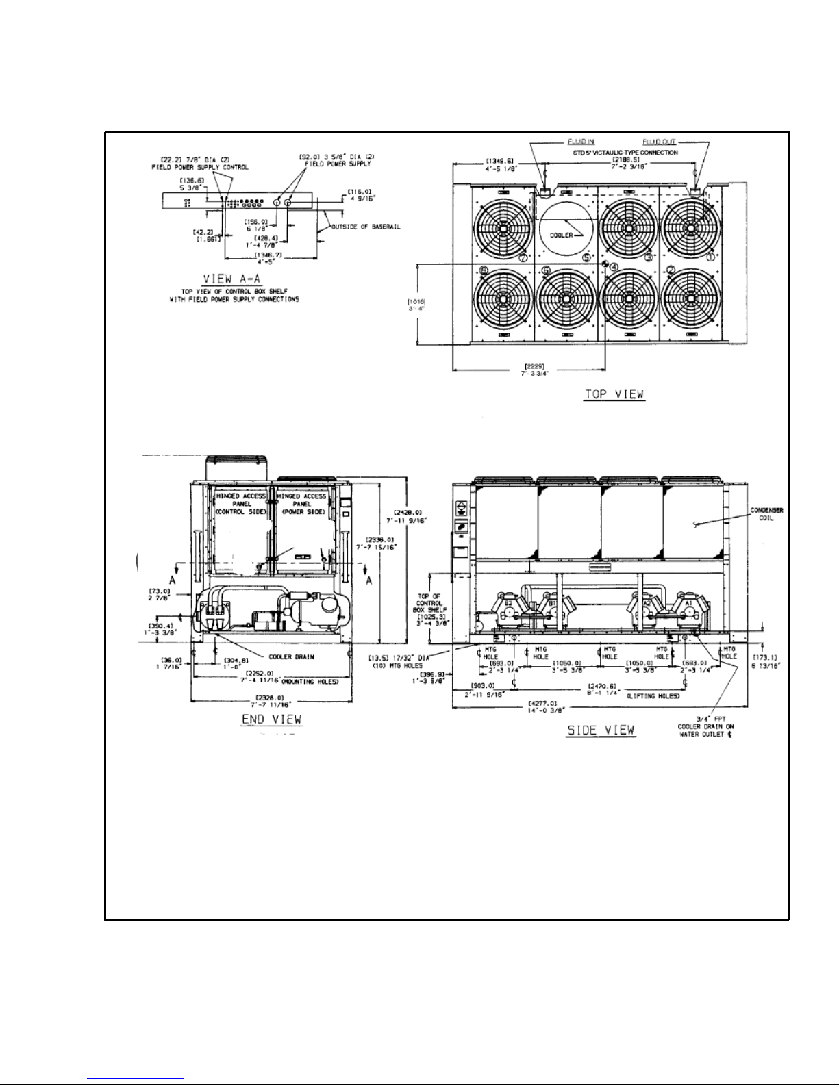
Base unit dimensions — 30GTN,GTR100,110
NOTES:
1. Unit must have clearances for airflow as follows:
TOP – Do not restrict in any way.
ENDS – [1524] 5 ft
SIDES – [1829] 6 ft
2. Mounting holes may be used to mount unit to concrete pad. They are not
recommended for spring isolator location.
3. If spring isolators are used, a perimeter support channel between the unit
and isolators is recommended.
4. Dimensions in [ ] are millimeters.
Page 15
15
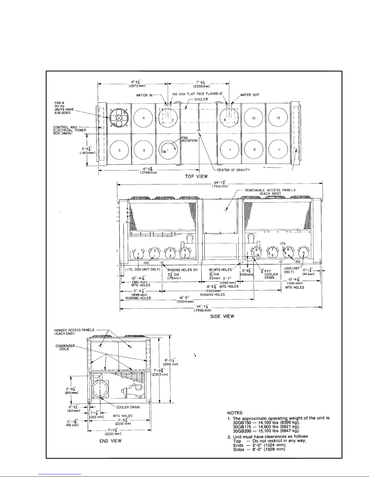
Base unit dimensions — 30GBN,GBR150-200,
300A/B-400A/B
Page 16

16
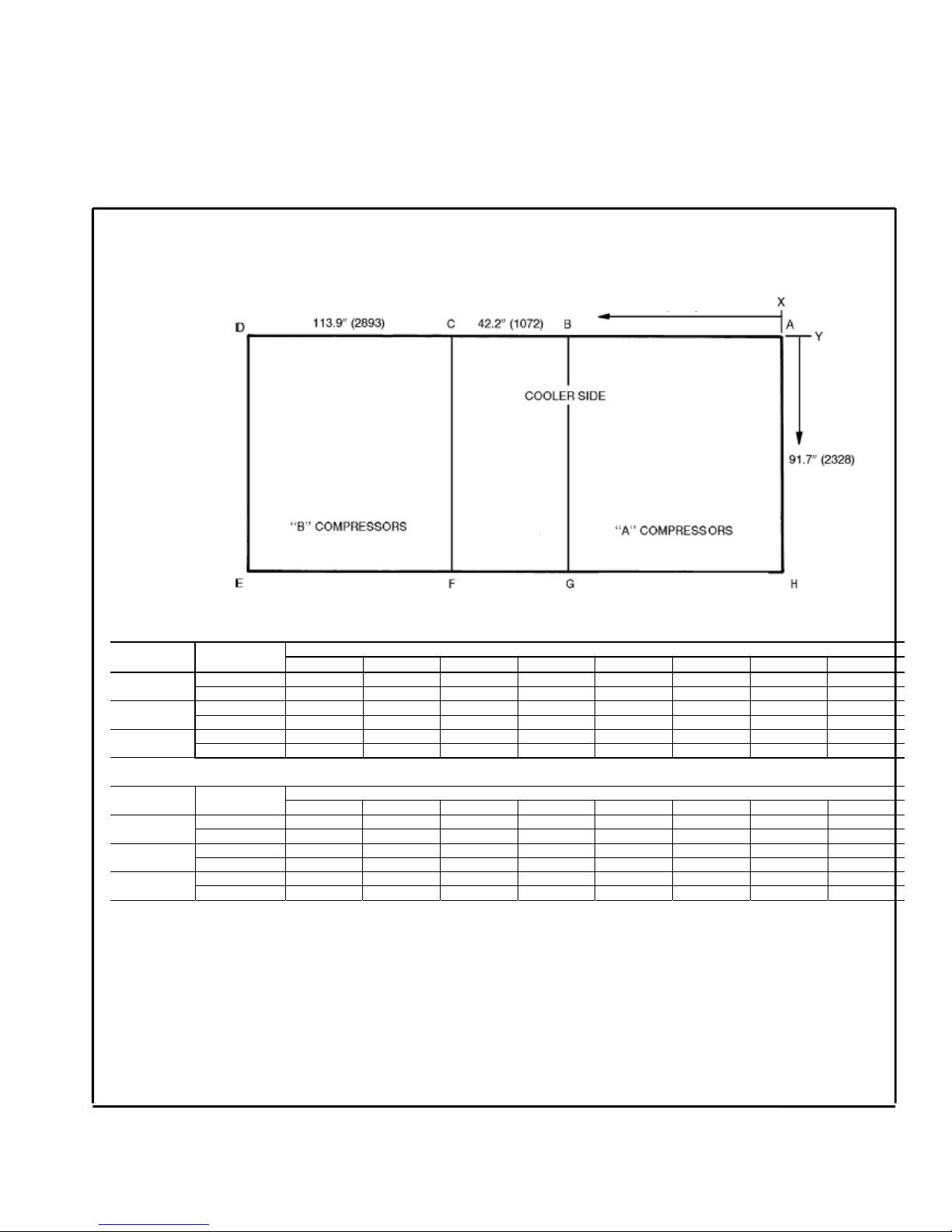
Base unit dimensions —
mounting weights (approximate)
LEGEND
C-AL – Copper Tubing, Aluminium Fins
C-C – Copper Tubing, Copper Fins
NOTE: If spring isolators are used, a perimeter support channel between the unit and the isolators is recommended.
RIGGING CENTER OF GRAVITY
050 060 070 080 090 100,110
UNIT SIZE
30GTN,GTR
in. mm in. mm in. mm in. mm in. mm in. mm
X
Dimension
47.0 1194 58.3 1481 58.5 1486 69.6 1769 67.3 1710 87.8 2229
Y
Dimension
41.9 1064 42.9 1090 42.0 1067 42.0 1067 38.8 984 40.0 1016
lb kg
UNIT SIZE
30GTN,GTR
CONDENSER
COIL
ABCDABCD
C-AL 1074 968 889 986 487 439 403 447
050
C-C 1182 1076 997 1095 536 488 452 496
C-AL 1269 1151 123 1238 575 522 509 561
060
C-C 1373 1255 1227 1342 623 569 556 609
C-AL 1508 1369 1226 1350 684 621 556 612
070
C-C 1664 1526 1383 1508 755 692 627 684
C-AL 1650 1730 1680 1660 750 786 764 755
080
C-C 1830 1910 1863 1842 832 868 847 837
C-AL 1833 1864 1724 1714 833 847 784 779
090
C-C 2014 2040 1907 1899 915 927 867 863
C-AL 2222 2222 2133 2133 1010 1010 970 970
100
C-C 2460 2460 2370 2370 1118 1118 1077 1077
C-AL 2271 2271 2149 2149 1032 1032 976 976
110
C-C 2508 2508 2387 2387 1140 1140 1085 1085
Page 17
17
Base unit dimensions —
mounting weights (approximate) (cont)
lb
UNIT SIZE
30GBN,GBR
CONDENSER
COIL
ABCDEFGH
C-AL 1261 2230 2230 1261 1353 2200 2200 1353
150, 300A/B
C-C 1377 2338 2338 1377 1467 2314 2314 1467
C-AL 1261 2230 2250 1350 1675 2275 2200 1353
175, 350A/B
C-C 1377 2338 2360 1467 1788 2380 2314 1467
C-AL 1350 2250 2250 1350 1675 2275 2275 1675
200, 400A/B
C-C 1467 2360 2360 1467 1788 2380 2380 1788
kg
UNIT SIZE
30GBN,GBR
CONDENSER
COIL
ABCDEFGH
C-AL 573 1014 1014 573 615 1000 1000 615
150, 300A/B
C-C 626 1063 1063 626 667 1052 1053 667
C-AL 573 1014 1023 614 761 1034 1000 615
175, 350A/B
C-C 626 1063 1073 667 813 1082 1053 667
C-AL 614 1023 1023 614 761 1034 1034 761
200, 400A/B
C-C 667 1073 1073 667 813 1082 1083 813
LEGEND
C-AL – Copper Tubing, Aluminium Fins
C-C – Copper Tubing, Copper Fins
NOTE: If spring isolators are used, a perimeter support channel between the unit and the isolators is recommended.
Page 18
18
Application data
MINIMUM COOLER FLUID FLOW RATES
AND MINIMUM LOOP VOLUME
Leveling unit
Unit must be level within 1/8-in. per ft when installed to
ensure proper oil return to the compressors.
While most outdoor locations are suitable for 30GTN,GTR,
GBN,GBR units, the roof is a common site that presents a
problem if roof has been pitched to aid in water removal. To
assure proper oil return, be sure that unit is level, particularly
in its major lengthwise dimension, as compressor oil return
piping runs in that direction.
I
t should be determined prior to installation if any specia
l
treatment is required to assure a level installation.
Cooler fluid temperature
1. Maximum leaving chilled fluid temperature (LCWT) for
unit is 70 F (21 C). Unit can start and pull down with up
to 95 F (35 C) entering-fluid temperature due to MOP
(maximum operating pressure) feature of the TXV. For
sustained operation, it is recommended that entering-fluid
temperature not exceed 85 F (29.4 C).
2. Minimum LCWT for standard unit is 40 F (3.3 C). It is
permissible to use a standard microprocessor-controlled
ComfortLink™ chiller with leaving-fluid temperatures in
the range of 34 to 39.9 F (1° to 3.28 C) only if a
protective brine solution (20% antifreeze solution, or
greater) is used. (See Controls and Troubleshooting
literature for further information.)
Medium temperature brine application
Application of chiller for brine duty within the 39.9 to 15 F
(3.3 to –9.4 C) range is possible by ordering the proper
factory-installed brine option. For ratings below 38° F (3.3
C) LCWT, contact your local Carrier representative.
Leaving-fluid temperature reset
Reset reduces compressor power usage at part load when
design LCWT is not necessary. Humidity control should be
considered since higher coil temperatures resulting from
reset will reduce latent heat capacity. Three reset options are
offered, based on the following:
Return-fluid temperature — Increases LCWT temperature
set point as return (or entering) fluid temperature decreases
(indicating load decrease). Option may be used in any
application where return fluid provides accurate load
indication. Limitation of return fluid reset is that LCWT may
only be reset to value of design return fluid temperature .
Outdoor-air temperature — Increases LCWT as outdoo
r
ambient temperature decreases (indicating load decrease).
This reset should be applied only where outdoor ambient
temperature is an accurate indication of load. An accessory
thermistor is required.
Space temperature — Increases LCWT as space
temperature decreases (indicating load decrease). This reset
should be applied only where space temperature is an
accurate indication of load. An accessory thermistor is
required.
For details on applying a reset option, refer to uni
t
Controls and Troubleshooting literature. Obtain ordering
part numbers for reset option from current price pages or
contact your local Carrier representative.
Cooler flow range
Ratings and performance data in this publication are for
a cooling temperature rise of 10° F (6° C), and are
suitable for a range from 5 to 20 F (2.8 to 11.1 C)
temperature rise without adjustment. The ComfortLin
k
chillers may be operated using a different temperature
range, provided flow limits are not exceeded. Fo
r
minimum flow rates, see Minimum Cooler Fluid Flow
Rates and Minimum Loop Volume table. High flow rate
is limited by pressure drop that can be tolerated. I
f
another temperature range is used, apply LCWT
correction as given in Selection Procedure example on
page 53.
APPLICATION V N
Normal Air Conditioning 33.25
Process Type Cooling 6 to 10 6.5 to 10.8
Low Ambient Unit Operation 6 to 10 6.5 to 10.8
NOTES:
1. Minimum flow based on 1.0 fps (0.30 m/s) velocity in cooler without special
cooler baffling.
2. Minimum Loop Volumes:
Gallons = V x ARI Cap. in tons
Liters = N x ARI Cap. in kW
MINIMUM COOLER
FLOW RATE
MINIMUM LOOP
VOLUME
UNIT SIZE
30GTN,GTR,GBN,GBR
Gpm L/s Gal L
050 37.7 2.38 153 580
060 47.5 3.00 181 684
070 47.5 3.00 210 796
080 66.7 4.20 243 920
090 59.5 3.75 272 1029
100 84.1 5.30 301 1138
110 81.1 5.30 333 1260
150, 300A/B 192.0 6.90 502 1900
175, 350A/B 192.0 6.90 568 2150
200, 400A/B 192.0 6.90 635 2403
Page 19
19
Minimum cooler flow (maximum cooler temperature
rise) — The minimum cooler flow for standard units is
shown in Minimum Cooler Fluid Flow Rates and Minimum
Loop Volume tables. When gpm (L/s) required is lower (o
r
rise higher), follow recommendations bel ow:
a. Multiple smaller chillers may be applied in series, each
providing a portion of the design temperature rise.
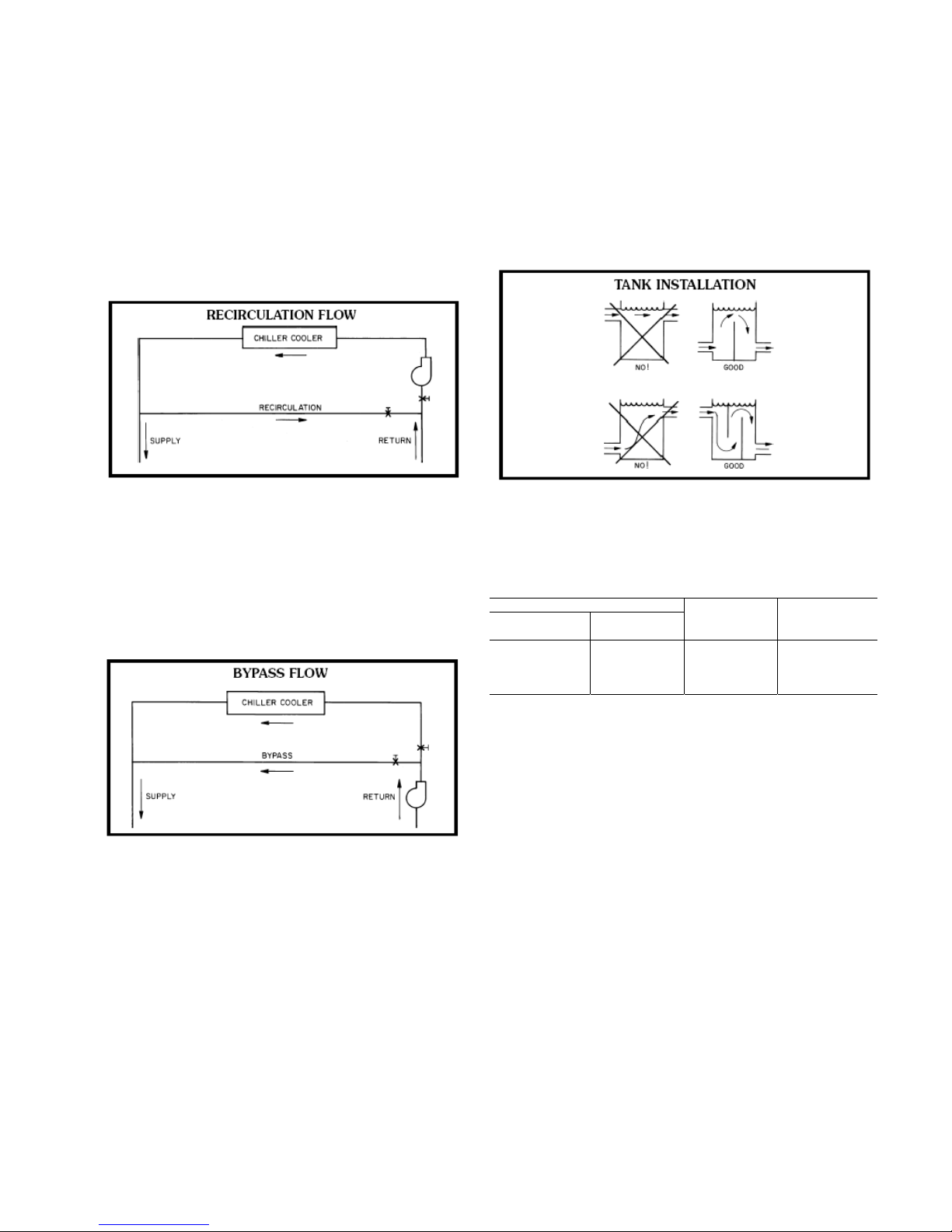
b. Cooler fluid may be recirculated to raise flow rate.
However, mixed temperature entering cooler must be
maintained a minimum of at least 5° F (2.8° C) above the
LCWT.
c. Special cooler baffling is required to allow minimum flow
rate to be reduced.
N
OTE: Recirculation flow is shown below.
Maximum cooler flow — The maximu m cooler flow (> 5
gpm/ton or < 5° F rise [> 0.09 L/s .kW or < 2.7° C rise])
results in practical maximum pressure drop through cooler.
1. Return fluid may bypass the cooler to keep pressure drop
through cooler within acceptable limits. This permits a
higher .T with lower fluid flow through cooler and mixing
after the cooler.
2. Special cooler baffling to permit a cooler flow rate
increase of 10% is available by special order.
N
OTE: Bypass flow is shown below.
Variable cooler flow rates — Variable rates may be applied
to standard chiller. Unit will, however, attempt to maintain a
constant leaving chilled fluid temperature. In such cases,
minimum flow must be in excess of minimum flow given in
Minimum Cooler Fluid Flow Rates and Minimum Loop
Volume table, and flow rate must change in steps of less than
10% per minute. Apply 6 gal.
p
er ton (6.5 L per kW) wate
r
loop volume minimum if flow rate changes more rapidly.
Fluid loop volume — The volume in circulation must equal o
r
exceed 3 gal. per nominal ton (3.25 L per kW) of cooling for
temperature stability and accuracy in normal air-conditioning
applications. (For example, a 30GBN200 would require 635
gal. [2403 L].) In process cooling applications, or for operation
at ambient temperature below 32 F (0° C) with low loading
conditions, there should be from 6 to 10 gal. per ton (6.5 to
10.8 L per kW). To achieve this volume, it is often necessary to
install a tank in the loop. Tank should be baffled to ensure there
is no stratification and that water (or brine) entering tank is
adequately mixed with liquid in the tank.
NOTE: Tank installation is shown below.
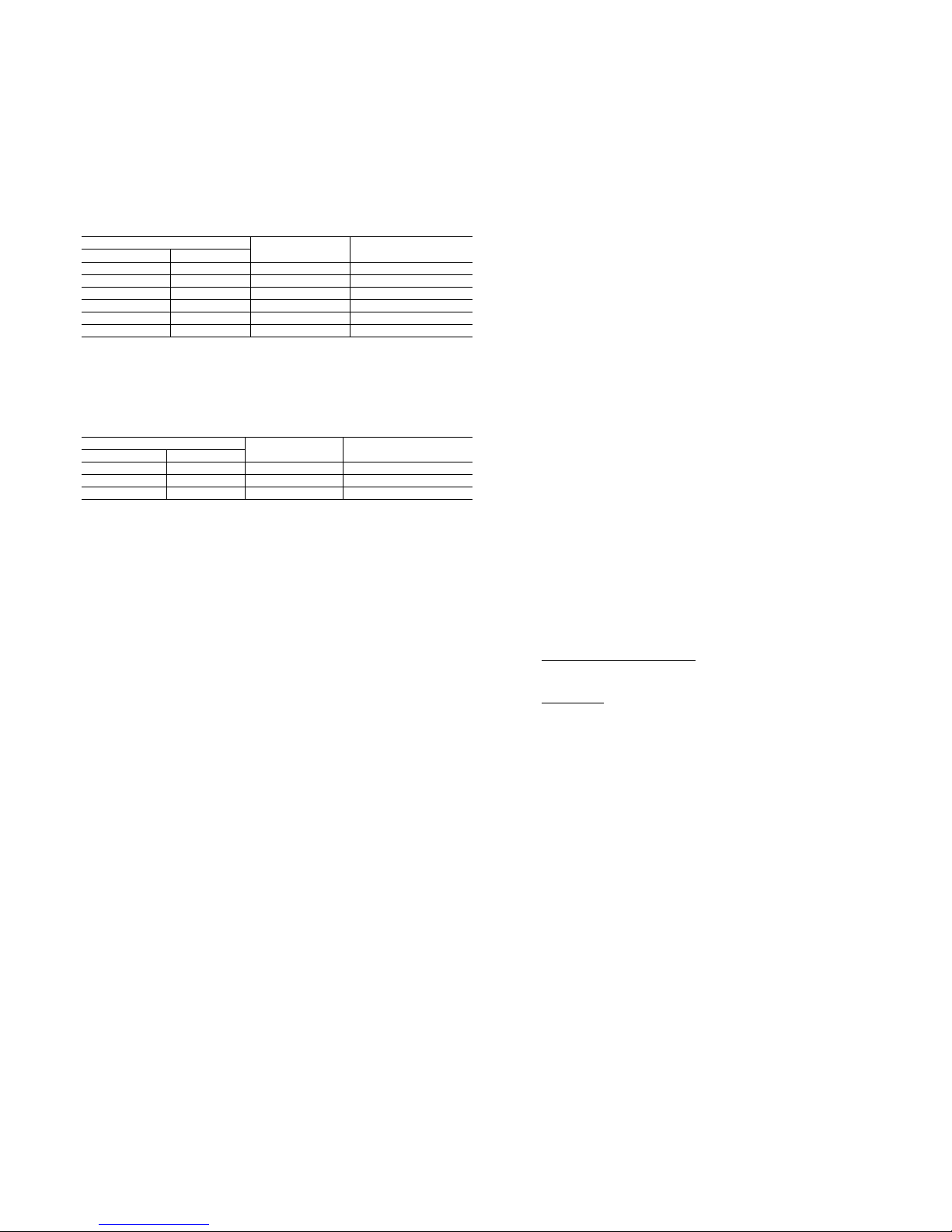
Cooler fouling factor — The fouling factor used to calculate
tabulated ratings was .00010 ft
2 • hr • °F/Btu (.000018 m2 •
°C/W). As fouling factor is increased, unit capacity decreases
and compressor power increases. Standard ratings should be
corrected using following multipliers:
FOULING FACTOR
English
(ft
2 .hr.°F/Btu)
SI
(m2 .°C/W)
CAPACITY
MULTIPLIER
COMPRESSOR
POWER
MULTIPLIER
.00025 .000044 0.991 0.995
.00050 .000088 0.977 0.987
.00075 .000132 0.955 0.979
.00175 .000308 0.910 0.952
Cooler protection — Protection against low ambient freeze-up
is required for unit operation in areas that experience
temperatures below 32 F (0° C). Protection should be in the
form of inhibited ethylene glycol or other suitable brine.
Even though unit cooler is equipped with insulation and an
electric heater that helps prevent freeze-up, it does not protect
fluid piping external to unit or if there is a power failure. Use
only antifreeze solutions approved for heat exchanger duty.
Use of automotive-type antifreezes is not recommended
because of the fouling that can occur once their relatively shortlived inhibitor breaks down.
Draining cooler and outdoor piping is recommended if
system is not to be used during freezing weather conditions.
See Low Ambient Temperature Operation section page 46.
Page 20
20
Application data (cont)
Condenser
Altitude correction factors — Correction factors must be
applied to standard ratings at altitudes above 2000 ft (610 m)
using the following multipliers:
ALTITUDE CAPACITY
ft m
CAPACITY
MULTIPLIER
COMPRESSOR
POWER MULTIPLIER
0 0 1.00 1.00
2000 610 0.99 1.01
4000 1220 0.98 1.02
6000 1830 0.97 1.03
8000 2440 0.96 1.04
10000 3050 0.95 1.05
Condenser airflow — Airflow restrictions on units with
standard fans will affect the unit capacity, condenser head
pressure, and compressor power input. Correction factors to be
applied for external static restrictions up to 0.2 in. wg (50 Pa)
are as follows:
EXTERNAL STATIC
in. wg Pa
CAPACITY
MULTIPLIER
COMPRESSOR
POWER MULTIPLIER
0.0 0.0 1.000 1.00
0.1 25 0.986 1.01
0.2 50 0.968 1.03
High ambient temperature
High outdoor ambient chiller start-up and operation (fully
loaded) is possible for standard 30GTN,GBN chillers at
ambient temperatures up to 125 F (52 C) at nominal voltage. In
some cases, where return water temperature is expected to
exceed 60 F (15.5 C), an accessory kit may be required.
Low ambient temperature operation
With certain field provisions as described below, units will start
and operate down to 0° F (–18 C).
NOTE: Minimum load on chiller must be above minimum step
of unloading.
Antifreeze solution — Inhibited ethylene glycol or other
suitable corrosion-resistant anti-freeze solution must be field
supplied and installed in all units for unit operation below 32 F
(0° C). Solution must be added to fluid loop to protect loop
down to 15° F (8° C) below minimum operating ambient
temperature. Concentration should be based on expected
minimum temperature and either “Burst” or “Freeze”
protection levels.
Provide sufficient volume in the chilled fluid loop — At least 6
gal per ton (6.5 L per kW) of refrigeration is the recommended
minimum for a moderate system load.
Freeze versus burst protection — If chiller operation is not
required during winter/off season, lower glycol concentrations
based on “burst” protection criteria may be considered. Often
use of burst protection results in lower fluid costs and has less
impact on chiller cooler capacity and flow rate. Consult glycol
fluid manufacturers for burst protection recommendations and
fluid specifications.
Capacity correction (antifreeze)
I
nhibited ethylene glycol (or other suitable brine) should be
used in installations where subfreezing temperatures are
expected. Unit performance data must be corrected for the
addition of inhibited ethylene glycol as shown in following
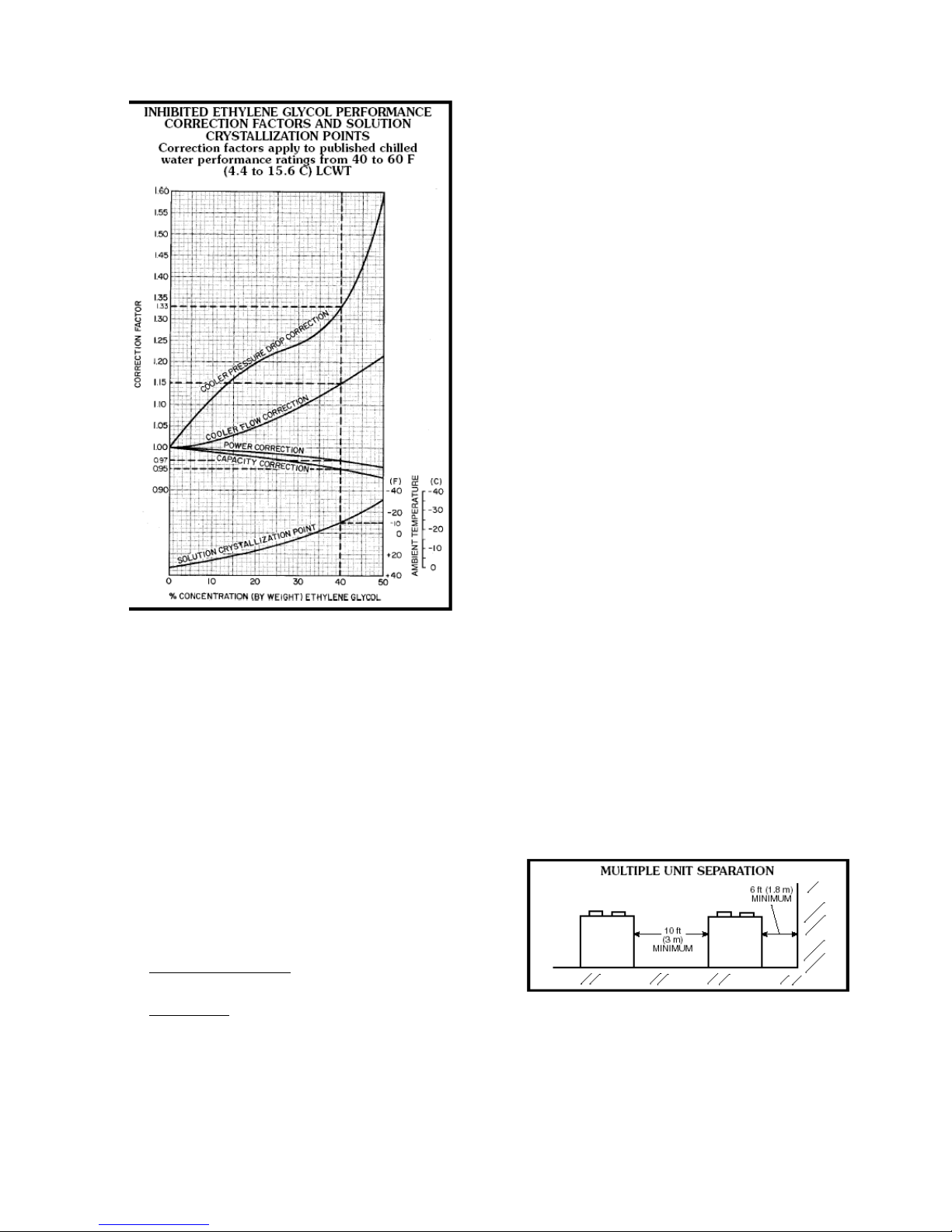
example. Correction factors can be derived from curves in the
Inhibited Ethylene Glycol Performance chart at right.
Additional performance information on this and other fluids is
available in Carrier’s Electronic Catalog (E-CAT) software
program. “Slush” and “Burst” concentration may also be
considered for winter shutdown protection and unit operation is
not required.
Example: English — Where a 5 F outdoor temperature is
anticipated, determine concentration of inhibited ethylene
glycol to protect system to –10 F ambient temperature at zero
flow.
Enter the solution crystallization point curve (at right) at –10
F; read that 40% concentration of inhibited ethylene glycol is
required to prevent crystals from forming in solution.
Consider the 30GTN110 unit from the Selection Procedure
example on page 53 (refer to correction curves at 40%
solution).
Correct unit capacity — On the capacity correction curve in
chart on page 47, read 0.95.
Corrected capacity = 0.95 x determined capacity
= 0.95 x 112.6
= 107.0 tons
Correct cooler water flow — On the cooler flow correction
curve on page 47, read 1.15.
Chilled water flow (at corrected capacity)
= 24 x corrected cap. in tons = U.S. gpm
temperature rise F
= 24 x 107.0 = 183.4 U.S. gpm
14°
Chilled water flow (40% solution) = 1.15 x 183.4
= 210.9 U.S. gpm
Correct cooler pressure drop — On cooler pressure drop
correction curve on page 47, read 1.33.
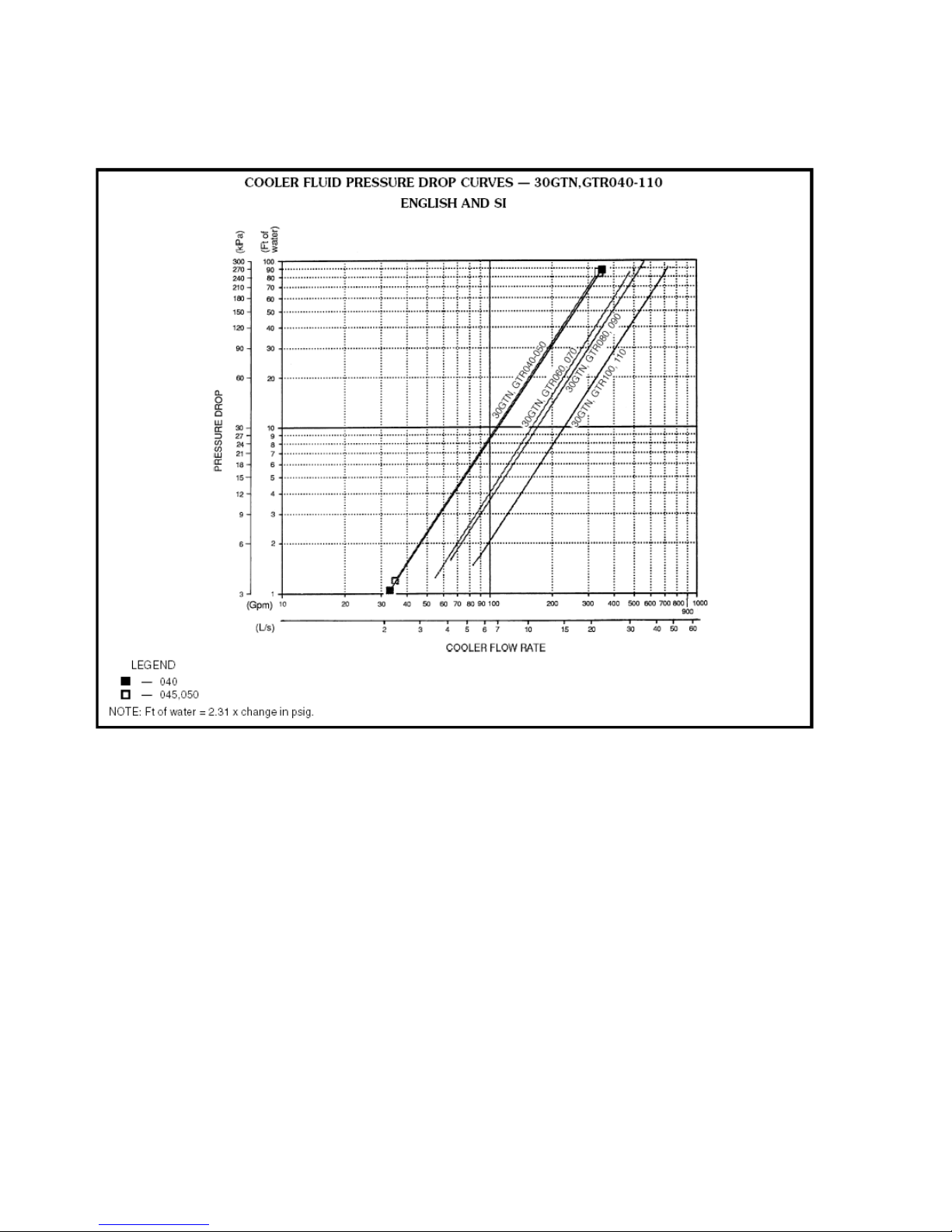
On cooler pressure drop curve on page 49, for 210.9 gpm, read
pressure drop = 8.1 ft water gage. The pressure drop for 40%
solution = 1.33 x 8.1 = 10.8 ft water.
Correct compressor power input (kW) — On power correction
curve below, read 0.97 correction factor at 40% ethylene glycol
concentration.
Power input from Selection Procedure example
= 126.1 kW.
Corrected power input = 0.97 x 126.1 = 122.3 kW
Page 21
21
Example: SI — Determine concentration of inhibited
ethylene glycol to protect the system to –23 C ambient
temperature at zero flow.
Enter the solution crystallization point curve abov e,
at –23 C, read 40% concentration inhibited ethylene
glycol is required to prevent crystals from forming in
solution.
Consider 30GTN110 unit selected from the Selection
Procedure example (refer to correction curves at 40%
solution).
Correct unit capacity — On glycol performance
capacity correction curve above, read 0.95.
Corrected capacity = 0.95 x determined capacity
= 0.95 x 379.7
= 360.7 kW
Correct chilled water flow — On cooler flow
correction
curve above, read 1.15.
Chilled water flow (at corrected capacity)
= 0.239 x corr. cap. in kW = L/s
temperature rise C
= 0.239 x 360.7 = 11.1 L/s
7.8°
Chilled water flow (40% solution) = 1.15 x 11.1
= 12.8 L/s
Correct cooler pressure drop — On cooler pressure drop
correction curve on this page, read 1.33.
On cooler pressure drop curve on page 49, for 12.8 L/s,
read pressure drop of 24 kPa. The pressure drop for 40%
solution = 1.33 x 24 = 31.92 kPa.
Correct compressor power input (kW) — On the power
correction curve on this page, read 0.97 correction factor
at 40% ethylene glycol concentration.
Power input from Selection Procedure example
= 123.2 kW.
Corrected power input = 0.97 x 123.2 = 119.5 kW.
Oversizing chillers
Oversizing chillers by more than 15% at design conditions
must be avoided as the system operating efficiency is
adversely affected (resulting in greater or excessive
electrical demand). When future expansion of equipment is
anticipated, install a single chiller to meet present load
requirements and add a second chiller to meet the additional
load demand.
It is also recommended that 2 smaller chillers be installed
where operation at minimum load is critical. The operation
of a smaller chiller loaded to a greater percentage ove
r
minimum is preferred to operating a single chiller at or nea
r
its minimum recommended value.
Hot gas bypass should not be used as a means to allow
oversizing chillers. Hot gas bypass should be given
consideration where substantial operating time is anticipated
below the minimum unloading step.
Multiple chillers
Where chiller capacities greater than 200 tons (703 kW) are
required, or where stand-by capability is desired, chillers
may be installed in parallel. Units should be of equal size to
ensure balanced fluid flows. Where a large temperature drop
(> 25° F [13.9° C]) is desired, chillers may be installed in
series. Fluid temperature sensors need not be moved for
multiple chiller operation. A 10 ft (3 m) separation is
required between units for airflow, and a 6 ft (1.8 m)
distance is required from units to obstructions. See Multiple
Unit Separation figure below. See Base Unit Dimensions
section on pages 27-39 for service clearances.
Unit software is capable of controlling two units as a
single plant. Refer to Controls, Start-Up, Operation, Service,
and Troubleshooting guide for further det ai l s .
Page 22

22
Application data (cont)
Condenser coil protection
Electrical/utility interests
Energy management — Use of energy management practices
can significantly reduce operating costs, especially during offpeak modes of operation. Demand limiting and temperature
reset are 2 techniques for accomplishing efficient energy
management. See Demand Limiting (also called load shedding)
section below and Leaving-Fluid Temperature Reset section on
page 44 for further details.
Demand limiting (also called load shedding) — When
a
utility’s demand for electricity exceeds a certain level, loads are
shed to keep electricity demand below a prescribed maximum
level. Typically, this happens on hot days when air
conditioning is most needed.
Demand may be limited on unit by resetting fluid
temperature, or by unloading the chiller to a given
predetermined percentage of the load. Demand limit may also
be driven by an external 4 to 20 mA signal. These features
require a signal from an intelligent central control. Do not cycle
demand limiter for less than 10 minutes on and 5 minutes off.
Duty cycling cycles electrical loads at regular intervals
regardless of need. This reduces the electrical operating costs
of building by “fooling” demand indicating devices. Duty
cycling of compressors or fans is not recommended since
motor winding and bearing life suffer from constant cycling.
Remote on-off control
Remote on-off control may be applied by hard-wired
connection (see Controls and Troubleshooting literature) or by
connection to a Carrier Comfort Network (CCN).
Part-wind start
This is not generally required on 30GTN,GBN chillers due to
use of multiple compressors allowing smaller electrical load
increments, but is available if required. Maximum
instantaneous current flow (see ICF in Electrical Data table on
pages 78-81) should be used in determining need.
Strainers
It is recommended that a strainer with a minimum of 20 mesh
be installed in the cooler fluid inlet line, just ahead of and as
close as possible to the cooler.
Copper-fin coils provide increased corrosion resistance in
moderate coastal environments where industrial air pollution
is not present. All copper coils eliminate bi-metallic
construction to eliminate the potential for galvanic corrosion.
Application in industrial environments is not recommended
due to potential attack from sulfur, sulfur oxide, nitrogen
oxides, carbon and several other industrial airborne
contaminants. In moderate seacoast environments,
copper-fin coils have extended life compared to standard or
pre-coated aluminum-fin coils.
Page 23
23
Page 24

24
Selection procedure — English (with 30GTN example)
Selection procedure — SI (with 30GTN example)
N
OTE: The Carrier electronic catalog provides quick, easy
computer selection of Carrier chillers. The catalog is
available from your local Carrier representative.
I Determine unit size and operating conditions
required to provide specified capacity at given
conditions:
Capacity required . . . . . . . . . . . . . . . . . . …112 tons
Leaving chilled water temperature (LCWT) . . . 45 F
Chilled water temperature rise . . . . . . . . . . . 14° F
Condenser entering-air temperature (CEAT) . . 95 F
Loop volume . . . . . . . . . . . . . . . . . . . . . . 350 gal.
Ratings are based on 10° F rise and are suitable for a
temperature rise range from 5° to 15° F without
adjustment. In this case, however, greater accuracy is
desired.
II Correct LCWT for 14° F cooler water temperature
rise.
Enter LCWT correction curve (below) at 14° F and
read a correction of 0.3 F. Corrected LCWT is,
therefore, 45 + 0.3 = 45.3 F.
III Determine capacity, unit size, and power input.
Enter Cooling Capacities table at given CEAT and
LCWT — 95 F and 45 F, respectively.
Read down capacity column until the capacity nearest to
but higher than specified required capacity is reached. In
this case, 113 tons is delivered by a 30GTN110.
Interpolate between 45 F and 46 F to find determined capacity
and power input at corrected LCWT (45.3 F). Values are:
Capacity . . . . . . . . . . . . . . . . . . . . . . . 113.6 tons
Power input . . . . . . . . . . . . . . . . . . . . . 136 kW
IV Calculate corrected cooler water flow.
Water flow = 24 x corr cap. in tons = U.S. gpm
temperature rise °F
=24 x 113.6 = 194.8 U.S. gpm
14
V Calculate the cooler pressure drop.
Enter cooler pressure drop curve (page 32) at the corrected
flow rate (194.8 U.S. gpm) and read, for the 30GTN110, a
pressure drop of 10.4 ft of water.
VI Check loop volume and cooler water flow rate.
Minimum loop volume, from application data, is 333 gal. for
30GTN110. Therefore, given volume of 350 gal. is
satisfactory. Minimum water flow rate, from application data,
is 73 gpm for 30GTN110. Flow rate of 194.8 gpm is well
above minimum required.
I Determine unit size and operating conditions required
to provide specified capacity at given conditions:
Capacity required . . . . . . . . . . . . . . . . . . . 380 kW
Leaving chilled water temperature (LCWT) . . . . 6 C
Chilled water temperature rise . . . . . . . . . . . 7.8° C
Condenser entering air temperature (CEAT) . . 35 C
Loop volume . . . . . . . . . . . . . . . . . . . . . . 1400 L
Ratings are based on 6 C rise and are suitable for a
temperature rise range from 2.8° to 8.3° C without
adjustment. In this case, however, greater accuracy is
desired.
II Correct LCWT for 7.8° C cooler water temperature
rise.
Enter LCWT correction curve (below) at 7.8° C and
read a correction of 0.14 C. Corrected LCWT is,
therefore, 6 + 0.14 = 6.1 C.
III Determine capacity, unit size, and power input.
Enter Cooling Capacities table at given CEAT and
LCWT — 35 C and 6 C, respectively.
Read down the capacity column until the capacity nearest
to but higher than the specified required capacity is
reached. In this case, 381.7 kW is delivered by a 30GTN110.
Interpolate between 6 C and 7 C to find the determined
capacity and power input at corrected LCWT
(6.1 C).
Values are:
Capacity . . . . . . . . . . . . . . . . . . . . . . . . 383 kW
Power input . . . . . . . . . . . . . . . . . . . . . 132.6 kW
IV Calculate corrected cooler water flow.
Water flow = 0.239 x corr cap. in kW = L/s
temperature rise °C
= 0.239 x 383 = 11.7 L/s
7.8
V Calculate cooler pressure drop.
Enter cooler pressure drop curve (page 32) at corrected
flow rate (11.7 L/s) and read, for 30GTN110, a pressure
drop of 26.0 kPa.
VI Check loop volume and cooler water flow rate.
Minimum loop volume, from application data, is 1260 L
for 30GTN110. Therefore, given volume of 1400 L is
satisfactory. Minimum water flow rate, from application
data, is 4.6 L/s for 30GTN110. Flow rate of 11.7 L/s is
well above minimum required.
Page 25
25
Selection procedure – English and SI
Performance data
PART LOAD DATA, 50 Hz UNITS
PERCENT DISPLACEMENT — SEQUENCE A
30GTN,GTR,GBN,GBRCAPACITY
STEPS
050 060 070 080 090 100 110 150,300A/B 175,350A/B 200,400A/B
1
28 33 19 17 14 13 17 17 14 13
2
42 50 27 25 21 20 25 33 29 25
3
87 83 65 42 29 26 33 50 43 38
4
100 100 73 54 36 33 42 67 57 50
5
- - 92 62 43 40 50 83 71 63
6
- - 100 79 61 57 58 100 86 75
7
- - - 92 68 63 67 - 100 88
8
- - - 100 75 70 75 - - 100
9
- - - - 86 87 83 - - -
10
- - - - 93 93 92 - - -
11
- - - - 100 100 100 - - -
PART LOAD DATA, 50 Hz UNITS
PERCENT DISPLACEMENT — SEQUENCE B
30GTN,GTR,GBN,GBRCAPACITY
STEPS
050 060 070 080 090 100 110 150,300A/B 175,350A/B 200,400A/B
1
- - - 25141317 17 14 13
2
- - - 38212025 33 29 25
3
- - - 42292633 50 43 38
4
- - - 50363342 67 57 50
5
- - - 62434050 83 71 63
6
- - - 79 53 57 58 100 86 75
7
- - - 88 60 63 67 - 100 88
8
- - - 100 67 70 75 - - 100
9
- - - - 86 87 83 - - -
10
- - - - 93 93 92 - - -
11
- - - - 100 100 100 - - -
Page 26
26
Performance data (cont)
COOLING CAPACITIES - ENGLISH
CONDENSER ENTERING AIR TEMPERATURE (F)
85 95 105 115 125
UNIT SIZE
30GTN,GTR
GBN,GBR
LCWT
(F)
Cap.
Input
kW
Cooler
Flow
Rate
Cap.
Input
kW
Cooler
Flow
Rate
Cap.
Input
kW
Cooler
Flow
Rate
Cap.
Input
kW
Cooler
Flow
Rate
Cap.
Input
kW
Cooler
Flow
Rate
050 50.3 54.1 120.4 47.6 57.1 113.9 44.9 59.8 107.4 42.1 62.3 100.8 39.3 64.5 94.1
060 59.2 62.7 141.7 56.0 66.2 134.2 52.9 69.4 126.7 49.8 72.4 119.2 46.7 75.1 111.7
070 69.1 70.6 165.4 65.2 74.9 156.2 61.4 78.8 147.0 57.6 82.5 137.8 53.8 85.9 128.7
080 79.7 75.4 190.8 75.2 79.6 180.1 70.9 83.4 169.6 66.5 87.0 159.2 62.1 90.3 148.7
090 89.3 95.9 213.8 84.2 101.2 201.6 79.1 106.1 189.3 74.0 110.6 177.1 68.9 114.6 164.8
100 98.3 102.4 235.3 92.8 108.1 222.2 87.3 113.3 208.9 81.8 118.2 195.8 76.3 122.7 182.8
110 108.6 122.1 260.0 102.9 128.1 246.4 97.2 133.7 232.8 91.5 138.8 219.1 85.7 143.6 205.2
150,300A/B 164.4 175.8 392.9 155.0 184.6 370.5 145.7 192.3 348.3 136.2 199.3 325.7 126.9 205.6 303.3
175,350A/B 185.7 211.0 443.9 175.3 220.8 419.1 165.0 229.9 394.5 154.5 237.8 369.3 143.9 244.9 344.1
200,400A/B
40
203.7 244.6 486.9 192.4 255.6 460.0 181.3 265.6 433.4 170.1 274.7 406.6 158.8 282.8 379.7
050 52.1 55.1 124.8 49.3 58.2 118.2 46.5 61.0 111.5 43.7 63.6 104.7 40.9 66.0 97.9
060 61.3 63.9 146.9 58.1 67.5 139.2 54.9 70.9 131.5 51.7 74.0 123.8 48.5 76.8 116.1
070 71.6 71.9 171.4 67.7 76.4 162.1 63.7 80.5 152.7 5.8 84.3 143.3 55.9 87.8 133.9
080 82.6 76.9 197.9 78.1 81.3 187.1 73.6 85.3 176.2 69.1 89.0 165.5 64.6 92.4 154.7
090 92.6 97.9 221.9 87.3 103.4 209.2 82.1 108.5 196.7 76.9 113.1 184.1 71.6 117.4 171.5
100 102.1 104.5 244.6 96.5 110.4 231.1 90.8 115.9 217.4 85.2 121.0 204.0 79.5 125.7 190.6
110 112.8 124.8 270.2 106.9 131.0 256.0 101.0 136.9 242.1 95.1 142.2 227.9 89.2 147.2 213.8
150,300A/B 170.7 179.8 408.4 161.1 188.8 385.4 151.6 196.9 362.6 141.9 204.4 339.3 132.2 210.9 316.4
175,350A/B 192.8 215.8 461.3 182.3 226.1 436.0 171.6 235.4 410.4 160.8 243.9 384.8 150.1 251.4 359.1
200,400A/B
42
211.4 250.2 505.8 199.9 261.7 478.3 188.5 272.1 451.0 177.0 281.7 423.5 165.5 290.2 395.8
050 53.9 56.1 129.1 51.1 59.4 122.5 48.2 62.3 115.7 45.4 65.0 108.7 42.4 67.5 101.8
060 63.5 65.1 152.2 60.2 68.9 144.3 56.9 72.3 136.5 53.6 75.5 128.5 50.3 78.5 120.6
070 74.1 73.3 177.6 70.1 77.8 168.1 66.1 82.1 158.4 62.1 86.1 148.8 58.1 89.7 139.2
080 85.5 78.4 205.1 81.0 82.9 194.2 76.4 87.1 183.1 71.7 91.0 171.9 67.1 94.6 160.9
090 95.9 99.9 230.0 90.6 105.6 217.1 85.2 110.9 204.2 79.8 115.7 191.3 74.4 12.2 178.4
100 106.0 106.7 254.2 100.2 112.8 240.2 94.4 118.5 226.2 88.6 123.9 212.4 82.8 128.8 198.6
110 117.0 127.5 280.4 111.0 134.0 266.0 104.9 140.1 251.4 98.9 145.7 237.0 92.8 150.9 222.5
150,300A/B 177.3 183.8 424.5 167.4 193.1 400.7 157.6 201.6 377.2 147.6 209.4 353.3 137.6 216.3 329.5
175,350A/B 200.1 220.6 479.1 189.3 231.4 453.2 178.4 241.1 427.0 167.3 249.9 400.5 156.3 257.9 374.2
200,400A/B
44
219.4 255.9 525.2 207.7 267.9 497.2 195.9 278.7 468.9 184.2 288.8 441.0 172.2 297.7 412.3
050 54.8 56.7 131.5 52.0 59.9 124.7 49.1 63.0 117.8 46.2 65.7 110.8 43.2 68.2 103.7
060 64.6 65.7 154.9 61.3 69.5 146.9 57.9 73.1 138.9 54.6 76.3 130.9 51.2 79.4 122.9
070 75.4 73.9 180.8 71.3 78.6 171.1 67.3 82.9 161.4 63.2 87.0 151.6 59.2 90.7 141.9
080 87.1 79.2 208.9 82.4 83.8 197.6 77.8 88.1 186.5 73.1 92.0 175.3 68.4 95.7 164.0
090 97.6 100.9 234.1 92.2 106.7 221.1 86.8 112.1 208.1 81.3 117.1 194.9 75.8 121.6 181.8
100 108.0 107.8 259.0 102.1 114.0 244.8 96.2 119.9 230.7 90.3 125.3 216.6 84.5 130.3 202.6
110 119.0 128.9 285.5 113.0 135.5 271.0 106.9 141.7 256.4 100.8 147.4 241.7 94.6 152.8 226.9
150,300A/B 180.6 185.8 432.6 170.6 195.3 408.5 160.6 204.0 384.6 150.5 212.0 360.4 140.4 219.1 336.3
175,350A/B 204.0 223.2 488.5 192.9 234.0 461.9 181.8 244.0 435.4 170.7 253.1 408.9 159.5 261.2 381.9
200,400A/B
45
223.4 258.8 534.9 211.6 271.1 506.7 199.6 282.0 478.0 187.8 292.4 449.7 175.7 301.5 420.7
050 55.8 57.2 133.8 52.9 60.5 126.9 50.0 63.6 119.9 47.0 66.4 112.8 44.1 69.0 105.7
060 65.7 66.4 157.6 62.3 70.2 149.5 59.0 73.8 141.5 55.6 77.2 133.4 52.2 80.3 125.2
070 76.7 74.6 183.9 72.6 79.3 174.1 68.5 83.7 164.4 64.4 87.9 154.5 60.3 91.7 144.6
080 88.7 80.0 212.7 83.9 84.6 201.2 79.2 89.0 190.0 74.5 93.0 178.7 69.7 96.8 167.1
090 99.3 101.9 238.2 93.8 107.8 225.1 88.4 113.3 211.9 82.8 118.4 198.6 77.3 123.0 185.4
100 110.0 108.9 263.8 104.1 115.3 249.6 98.1 121.2 235.3 92.2 126.8 221.1 86.2 131.9 206.7
110 121.2 130.3 290.7 115.1 137.0 276.0 108.9 143.3 261.2 102.7 149.2 246.2 96.4 154.6 231.3
150,300A/B 184.0 187.8 440.7 173.8 197.6 416.3 163.7 206.4 392.1 153.5 214.6 367.6 143.3 221.8 343.1
175,350A/B 207.8 225.7 497.6 196.5 236.7 470.8 185.3 246.9 443.7 174.0 256.2 416.9 162.7 264.6 389.7
200,400A/B
46
227.5 261.7 544.9 215.5 274.2 516.2 203.5 285.4 487.5 191.4 296.0 458.6 179.3 305.4 429.4
050 57.7 58.2 138.4 54.7 61.7 131.4 51.8 64.9 124.2 48.8 67.8 117.0 45.7 70.5 109.7
060 68.0 67.6 163.2 64.5 71.6 154.9 61.1 75.3 146.6 57.6 78.8 138.3 54.1 82.0 129.9
070 79.3 75.9 190.4 75.1 80.8 180.3 71.0 85.4 170.3 66.8 89.7 160.3 62.6 93.7 150.1
080 91.8 81.5 220.2 86.9 86.4 208.6 82.0 90.8 196.9 77.2 95.1 185.4 72.4 99.0 173.7
090 102.7 103.9 246.6 97.2 110.1 233.2 91.6 115.8 219.7 85.9 121.1 206.2 80.2 125.9 192.5
100 114.1 111.1 273.8 107.9 117.7 259.0 101.9 123.9 244.5 95.7 129.7 229.8 89.6 135.0 215.1
110 125.5 133.1 301.3 119.2 140.1 286.2 113.0 146.6 271.1 106.6 152.7 255.8 100.2 158.4 240.5
150,300A/B 190.7 191.8 456.9 180.3 202.0 432.2 170.0 211.2 407.3 159.5 219.8 382.3 149.0 227.4 357.1
175,350A/B 215.4 230.7 516.2 203.9 242.2 488.7 192.4 252.8 461.2 180.9 262.5 433.5 - - -
200,400A/B
48
235.7 267.6 564.9 223.5 280.5 535.7 211.2 292.2 506.2 198.9 303.2 476.6 - - -
Page 27
27
Performance data (cont)
COOLING CAPACITIES - ENGLISH
CONDENSER ENTERING AIR TEMPERATURE (F)
85 95 105 115 125
UNIT SIZE
30GTN,GTR
GBN,GBR
LCWT
(F)
Cap.
Input
kW
Cooler
Flow
Rate
Cap.
Input
kW
Cooler
Flow
Rate
Cap.
Input
kW
Cooler
Flow
Rate
Cap.
Input
kW
Cooler
Flow
Rate
Cap.
Input
kW
Cooler
Flow
Rate
050 59.6 59.3 143.1 56.6 62.9 135.9 53.6 66.2 128.6 50.5 69.3 121.3 47.4 72.1 113.8
060 70.3 68.8 168.8 66.8 73.0 160.3 63.2 76.8 151.8 59.7 80.4 143.2 56.1 83.8 134.7
070 82.1 77.3 197.1 77.7 82.3 186.7 73.4 87.0 176.4 69.2 91.5 166.2 64.9 95.6 155.8
080 94.9 83.1 227.8 90.0 88.1 216.1 85.0 92.8 204.2 80.0 97.1 192.1 75.1 101.2 180.3
090 106.3 106.0 255.2 100.6 112.3 241.5 94.8 118.3 227.7 89.1 123.8 213.8 83.3 128.8 199.9
100 118.2 113.4 283.9 112.0 120.2 268.9 105.7 126.6 253.8 99.5 132.6 238.8 93.2 138.2 223.8
110 130.0 136.0 312.2 123.5 143.2 296.6 117.1 150.0 281.1 110.6 156.3 265.5 104.0 162.2 249.7
150,300A/B 197.6 195.9 473.8 187.0 206.5 448.4 176.5 216.1 423.1 165.6 225.0 397.2 154.9 233.0 371.3
175,350A/B 223.3 235.9 535.3 211.4 247.7 507.0 199.6 258.7 478.7 187.8 268.8 450.3 - - -
200,400A/B
50
244.1 273.6 585.4 231.7 287.0 555.5 219.1 299.2 525.3 206.4 310.6 494.9 - - -
050 69.5 64.6 167.2 65.4 68.2 157.2 61.2 71.4 147.3 57.1 74.4 137.3 53.0 77.0 127.4
060 79.9 73.7 192.2 75.2 77.9 180.9 70.6 81.7 169.8 66.0 85.1 158.7 61.4 88.2 147.7
070 95.1 83.6 228.9 90.2 89.1 216.9 84.2 93.8 202.5 78.4 98.0 188.5 72.6 101.9 174.6
080 106.6 89.0 256.4 100.1 93.9 240.8 93.7 98.4 225.3 87.3 102.4 210.1 81.0 106.1 195.0
090 122.0 114.8 293.5 114.2 121.1 274.8 106.6 126.7 256.3 98.9 131.8 238.0 - - -
100 138.3 123.8 332.7 129.7 130.7 312.1 121.3 137.0 291.8 113.0 142.8 271.7 104.7 148.0 251.9
110 153.6 150.9 369.5 145.6 158.7 350.3 136.4 165.1 328.0 127.4 171.0 306.5 118.6 176.4 285.2
150,300A/B 234.4 217.7 563.1 222.5 230.0 534.5 210.4 241.5 505.5 198.1 252.1 475.9 - - -
175,350A/B 264.6 262.8 635.5 251.5 276.8 604.1 238.3 289.9 572.4 - - - - - -
200,400A/B
60
288.8 305.2 693.7 274.9 320.6 660.2 260.7 335.1 626.3 - - - - - -
LEGEND
Cap. — Cooling Capacity Tons of Refrigeration
Input kW — Compressor Power Input
LCWT — Leaving Chilled Water Temperature (F)
NOTES:
1. Ratings apply to units with electronic or thermostatic expansion valves.
2. All ratings are in accordance with ARI (Air Conditioning and Refrigeration
Institute, U.S.A.) Standard 590-92, based on:
a. A cooler water temperature rise of 10° F. When greater accuracy is
desired, correct design LCWT, before entering rating tables, by
reference to the LCWT correction curve.
b. A fouling factor of 0.00025 in the cooler.
c. Refrigerant 22.
3. When a corrected LCWT is used, cooler pressure drop must also be corrected
for new LCWT:
a. Enter rating table for corrected LCWT. By interpolation, determine corrected
capacity (tons) and power input (kW) to compressor at its rated voltage.
b. Calculate corrected flow rate through the cooler:
= 24 x capacity in tons = U.S. gpm
temperature rise °F
c. On Cooler Pressure Drop chart (pages 32 and 33),enter cooler pressure
drop curve at corrected flow rate and read pressure drop.
4. When chilled water temperature rise is less than 5 F, high flow rate will normally
be accompanied by an excessive pressure drop. In such cases, contact
your Carrier representative for special selection of a cooler with wider baffle
spacing.
Page 28
28
Performance data (cont)
COOLING CAPACITIES – SI
CONDENSER ENTERING AIR TEMPERATURE (C)
30 35 40 45 50
UNIT SIZE
30GTN,GTR
GBN,GBR
LCWT
(C)
Cap.
Input
kW
Cooler
Flow
Rate
Cap.
Input
kW
Cooler
Flow
Rate
Cap.
Input
kW
Cooler
Flow
Rate
Cap.
Input
kW
Cooler
Flow
Rate
Cap.
Input
kW
Cooler
Flow
Rate
050 173.5 54.0 7.4 165.0 56.6 7.1 156.4 59.0 6.7 147.8 61.2 6.3 139.1 63.2 6.0
060 204.1 62.6 8.8 194.3 65.7 8.3 184.5 68.5 7.9 174.7 71.2 7.5 164.9 73.7 7.1
070 238.2 70.6 10.2 226.1 74.3 9.7 214.1 77.8 9.2 202.1 81.1 8.7 190.1 84.1 8.2
080 274.7 75.2 11.8 260.7 78.9 11.2 247.0 82.3 10.6 233.3 85.5 10.0 219.6 88.5 9.4
090 307.8 95.7 13.2 291.8 100.4 12.5 275.7 104.7 11.8 259.8 108.7 11.2 243.7 112.3 10.5
100 338.4 102.1 14.5 321.3 107.1 13.8 304.0 111.8 13.0 286.9 116.2 12.3 269.8 120.2 11.6
110 374.5 121.6 16.1 356.6 126.9 15.3 338.7 131.9 14.5 320.8 136.5 13.8 302.7 140.8 13.0
150,300A/B 566.8 175.4 22.5 537.6 183.0 21.3 508.4 189.9 20.2 478.7 196.2 19.0 449.4 201.9 17.8
175,350A/B 640.5 210.3 25.4 608.1 219.0 24.1 575.6 227.0 22.9 542.7 234.2 21.6 509.8 240.6 20.2
200,400A/B
4
702.8 243.9 27.9 667.9 253.6 26.5 632.6 262.3 25.1 597.4 270.5 23.7 562.2 277.9 22.3
050 179.1 54.9 7.7 170.4 57.6 7.3 161.7 60.1 6.9 152.9 62.5 6.6 144.0 64.6 6.2
060 210.8 63.7 9.1 200.8 66.9 8.6 190.7 69.8 8.2 180.7 72.6 7.8 170.6 75.1 7.3
070 245.9 71.7 10.6 233.6 75.6 10.0 221.4 79.3 9.5 209.1 82.7 9.0 196.9 85.8 8.5
080 283.8 76.6 12.2 269.7 80.4 11.6 255.5 84.0 11.0 241.5 87.3 10.4 227.5 90.4 9.8
090 318.1 97.5 13.7 301.6 102.3 13.0 285.2 106.8 12.3 268.8 111.0 11.5 252.5 114.8 10.8
100 350.4 104.0 15.1 332.6 109.2 14.3 314.9 114.1 13.5 297.5 118.7 12.8 279.9 122.9 12.0
110 387.4 124.1 16.6 369.0 129.6 15.9 350.6 179.0 15.1 332.3 239.5 14.3 313.9 144.0 13.5
150,300A/B 586.8 178.9 23.3 556.7 186.9 22.1 526.9 194.0 20.9 496.5 200.7 19.7 466.2 206.6 18.5
175,350A/B 662.8 214.6 26.3 629.6 223.6 25.0 596.5 232.0 23.7 562.8 239.5 22.4 529.0 246.3 21.0
200,400A/B
5
727.1 248.9 28.9 691.4 259.0 27.5 655.3 268.1 26.0 619.3 276.7 24.6 583.2 284.4 23.2
050 184.8 55.8 7.9 176.0 58.7 7.6 167.1 61.3 7.2 158.1 63.7 6.8 149.0 65.9 6.4
060 217.6 64.8 9.4 207.3 68.1 8.9 197.0 71.1 8.5 186.7 74.0 8.0 176.4 76.6 7.6
070 253.9 72.9 10.9 241.4 76.9 10.4 228.8 80.7 9.8 216.3 84.2 9.3 203.8 87.5 8.8
080 292.9 78.0 12.6 278.7 81.9 12.0 264.3 85.6 11.4 249.8 89.0 10.7 235.5 92.3 10.1
090 328.5 99.3 14.1 311.8 104.3 13.4 294.9 108.9 12.7 278.1 113.3 12.0 261.3 117.2 11.2
100 362.5 106.0 15.6 344.5 111.4 14.8 326.4 116.4 14.0 308.3 121.2 13.3 290.3 125.6 12.5
110 400.4 126.6 17.2 381.7 132.3 16.4 362.9 137.6 15.6 344.1 142.6 14.8 325.1 147.2 14.0
150,300A/B 607.1 182.5 24.1 576.4 190.7 22.9 545.7 198.2 21.7 514.7 205.2 20.5 483.6 211.4 19.2
175,350A/B 685.8 219.0 27.3 651.7 228.4 25.9 617.9 237.1 24.6 583.2 244.9 23.2 549.0 252.1 21.8
200,400A/B
6
751.8 254.1 29.9 715.3 264.5 28.4 678.4 274.0 27.0 641.6 282.9 25.5 604.7 291.0 24.0
050 190.6 56.8 8.2 181.6 59.7 7.8 172.5 62.4 7.4 163.3 64.9 7.0 154.1 67.2 6.6
060 224.5 65.9 9.7 214.0 69.3 9.2 203.5 72.4 8.8 192.9 75.4 8.3 182.4 78.2 7.8
070 261.9 74.1 11.3 249.1 78.3 10.7 236.4 82.2 10.2 223.6 85.8 9.6 210.8 89.2 9.1
080 302.6 79.4 13.0 287.7 83.4 12.4 273.2 87.3 11.8 258.5 90.9 11.1 243.6 94.2 10.5
090 339.0 101.1 14.6 322.0 106.3 13.8 304.9 111.1 13.1 287.6 115.6 12.4 270.4 119.7 11.6
100 375.0 108.0 16.1 356.4 113.5 15.3 337.9 118.8 14.5 319.3 123.7 13.7 300.9 128.3 12.9
110 413.7 129.0 17.8 394.6 134.9 17.0 375.4 140.5 16.1 356.1 145.6 15.3 336.6 150.5 14.5
150,300A/B 628.1 186.2 25.0 596.3 194.6 23.7 564.9 202.4 22.5 533.2 209.7 21.2 501.3 216.2 19.9
175,350A/B 709.0 223.4 28.2 674.3 233.2 26.8 639.4 242.1 25.4 604.6 250.5 24.1 569.2 257.9 22.6
200,400A/B
7
777.1 259.3 30.9 739.8 270.1 29.4 702.0 279.9 27.9 664.8 289.3 26.4 626.6 297.6 24.9
050 196.5 57.7 8.5 187.3 60.8 8.1 178.1 63.6 7.7 168.7 66.2 7.3 159.3 68.6 6.9
060 231.4 67.0 10.0 220.8 70.5 9.5 210.1 73.8 9.0 199.3 76.8 8.6 188.5 79.7 8.1
070 270.1 75.3 11.6 257.1 79.6 11.1 244.2 83.6 10.5 231.0 87.4 9.9 218.0 91.0 9.4
080 312.3 80.8 13.4 297.1 85.0 12.8 282.1 88.9 12.1 267.2 92.7 11.5 251.9 96.1 10.8
090 349.7 102.9 15.1 332.3 108.3 14.3 314.9 113.3 13.6 297.4 118.0 12.8 279.7 122.2 12.0
100 387.4 110.0 16.7 368.7 115.7 15.9 349.7 121.2 15.0 330.8 126.2 14.2 311.8 131.0 13.4
110 427.1 131.6 18.4 407.6 137.7 17.5 388.0 143.4 16.7 368.3 148.8 15.9 348.3 153.8 15.0
150,300A/B 648.8 189.9 25.8 617.0 198.7 24.6 584.5 206.7 23.3 552.0 214.2 22.0 519.5 221.0 20.7
175,350A/B 732.9 228.0 29.2 697.4 238.0 27.8 661.5 247.3 26.3 625.7 255.9 24.9 589.4 263.6 23.5
200,400A/B
8
802.8 264.5 32.0 764.8 275.7 30.4 726.5 286.0 28.9 688.0 295.7 27.4 649.4 304.5 25.8
050 202.5 58.7 8.7 193.2 61.8 8.3 183.7 64.7 7.9 174.2 67.4 7.5 164.6 69.9 7.1
060 238.7 68.1 10.3 227.8 71.7 9.8 216.8 75.1 9.3 205.8 78.3 8.9 194.7 81.2 8.4
070 278.5 76.6 12.0 265.1 81.0 11.4 251.9 85.1 10.8 238.7 89.0 10.3 225.3 92.7 9.7
080 322.1 82.2 13.9 306.8 86.5 13.2 291.2 90.6 12.5 275.9 94.4 11.9 260.6 98.1 11.2
090 360.6 104.8 15.5 342.9 110.3 14.8 325.1 115.5 14.0 307.3 120.3 13.2 289.3 124.8 12.5
100 400.5 112.0 17.2 380.9 117.9 16.4 361.8 123.6 15.6 342.4 128.8 14.7 323.0 133.8 13.9
110 440.8 134.1 19.0 420.9 140.4 18.1 400.8 146.3 17.3 380.8 151.9 16.4 360.4 157.1 15.5
150,300A/B 670.3 193.6 26.7 637.5 202.6 25.4 604.9 211.0 24.1 571.4 218.8 22.8 538.0 226.0 21.4
175,350A/B 757.1 232.5 30.1 720.8 242.9 28.7 684.3 252.6 27.2 647.6 261.5 25.8 610.7 269.7 24.3
200,400A/B
9
829.0 269.9 33.0 790.1 281.4 31.5 751.0 292.0 29.9 711.8 302.2 28.3 672.3 311.3 26.8
Page 29

29
Performance data (cont)
COOLING CAPACITIES – SI
CONDENSER ENTERING AIR TEMPERATURE (C)
30 35 40 45 50
UNIT SIZE
30GTN,GTR
GBN,GBR
LCWT
(C)
Cap.
Input
kW
Cooler
Flow
Rate
Cap.
Input
kW
Cooler
Flow
Rate
Cap.
Input
kW
Cooler
Flow
Rate
Cap.
Input
kW
Cooler
Flow
Rate
Cap.
Input
kW
Cooler
Flow
Rate
050 208.6 59.7 9.0 199.1 62.9 8.6 189.5 65.9 8.2 179.8 68.7 7.7 169.9 71.3 7.3
060 246.0 69.3 10.6 234.9 73.0 10.1 223.7 76.4 9.6 212.3 79.7 9.1 201.0 82.8 8.7
070 287.2 77.8 12.4 273.4 82.3 11.8 259.8 86.6 11.2 246.4 90.6 10.6 232.8 94.4 10.0
080 332.0 83.6 14.3 316.5 88.1 13.6 300.8 92.3 13.0 284.9 96.3 12.3 269.3 100.0 11.6
090 371.8 106.6 16.0 353.7 112.3 15.2 335.5 117.7 14.4 317.2 122.7 13.7 298.9 127.4 12.9
100 413.6 114.1 17.8 393.8 120.2 17.0 373.9 126.0 16.1 354.2 131.4 15.3 334.4 136.6 14.4
110 455.1 136.7 19.6 434.4 143.2 18.7 414.0 149.3 17.8 393.4 155.1 16.9 372.7 160.5 16.1
150,300A/B 692.2 197.3 27.6 658.6 206.7 26.2 625.3 215.4 24.9 591.0 223.5 23.5 556.9 231.0 22.2
175,350A/B 782.2 237.3 31.2 744.7 247.9 29.7 707.3 257.9 28.2 670.0 267.2 26.7 632.3 275.7 25.2
200,400A/B
10
855.2 275.3 34.1 816.0 287.2 32.5 776.0 298.3 30.9 736.0 308.7 29.3 695.6 318.2 27.7
050 227.5 62.6 9.8 217.5 66.1 9.4 207.3 69.4 8.9 197.1 72.5 8.5 186.7 75.4 8.0
060 268.4 72.7 11.6 256.6 76.7 11.1 244.9 80.6 10.6 233.0 84.2 10.0 220.2 87.3 9.5
070 313.6 81.6 13.5 299.3 86.5 12.9 284.8 91.1 12.3 270.2 95.5 11.7 255.7 99.6 11.0
080 360.1 87.6 15.5 342.3 92.3 14.8 324.6 96.7 14.0 306.7 100.8 13.2 288.9 104.6 12.5
090 405.9 112.4 17.5 386.9 118.6 16.7 367.7 124.4 15.9 348.4 130.0 15.0 328.1 134.9 14.1
100 454.3 120.3 19.6 433.1 127.0 18.7 412.1 133.4 17.8 391.1 139.4 16.9 369.8 145.1 15.9
110 498.6 144.7 21.5 476.9 151.8 20.6 455.1 158.5 19.6 433.1 164.9 18.7 410.7 170.9 17.7
150,300A/B 760.4 208.9 30.3 724.5 219.2 28.9 688.5 228.8 27.5 652.3 237.9 26.0 - - -
175,350A/B 858.5 251.6 34.2 819.1 263.4 32.7 779.8 274.4 31.1 739.4 284.5 29.5 - - -
200,400A/B
13
938.1 292.1 37.4 896.0 305.1 35.7 853.5 317.1 34.0 811.0 328.7 32.3 - - -
050 243.1 65.0 10.5 230.0 68.2 9.9 216.9 71.1 9.4 203.8 73.8 8.8 190.7 76.2 8.2
060 279.5 74.2 12.1 264.6 77.9 11.4 249.9 81.3 10.8 235.3 84.5 10.2 220.9 87.3 9.5
070 336.4 84.6 14.5 317.2 89.1 13.7 298.3 93.3 12.9 279.8 97.2 12.1 261.4 100.8 11.3
080 372.8 89.5 16.1 352.2 93.9 15.2 331.8 97.9 14.3 311.7 101.6 13.5 291.8 105.0 12.6
090 426.6 115.5 18.4 402.0 121.1 17.3 377.6 126.2 16.3 353.5 130.8 15.3 329.6 135.0 14.2
100 483.7 124.5 20.9 456.6 130.7 19.7 429.8 136.4 18.5 403.3 141.7 17.4 377.1 146.5 16.3
110 540.3 152.1 23.3 511.4 158.5 22.1 482.9 164.4 20.8 454.6 169.9 19.6 426.4 174.9 18.4
150,300A/B 832.0 221.0 33.2 792.4 231.9 31.6 751.8 241.9 30.0 711.4 251.4 28.4 - - -
175,350A/B 939.3 266.8 37.5 897.4 279.5 35.8 855.4 291.5 34.1 812.8 302.7 32.4 - - -
200,400A/B
16
- 309.9 40.9 980.6 323.9 39.1 935.5 336.9 37.3 - - - - - -
LEGEND
Cap. — Cooling Capacity kW of Refrigeration
Input kW — Compressor Power Input
LCWT — Leaving Chilled Water Temperature (C)
NOTES:
1. Ratings apply to units with electronic or thermostatic expansion valves.
2. All ratings are in accordance with ARI (Air Conditioning and Refrigeration
Institute, U.S.A.) Standard 590-92, based on:
a. A cooler water temperature rise of 6° C. When greater accuracy is
desired, correct design LCWT, before entering rating tables, by
reference to the LCWT correction curve.
b. A fouling factor of 0.000018 in the cooler.
c. Refrigerant 22.
3. When a corrected LCWT is used, cooler pressure drop must also be corrected
for new LCWT:
a. Enter rating table for corrected LCWT. By interpolation, determine corrected
capacity (kW) and power input (kW) to compressor at its rated voltage.
b. Calculate corrected flow rate through the cooler:
= 0.239 x capacity in kW = L/s
temperature rise °C
c. On Cooler Pressure Drop chart (pages 32 and 33),enter cooler pressure
drop curve at corrected flow rate and read pressure drop.
4. When chilled water temperature rise is less than 3 C, high flow rate will
normally
be accompanied by an excessive pressure drop. In such cases, contact
your Carrier representative for special selection of a cooler with wider baffle
spacing.
Page 30
30
Electrical data
UNIT ELECTRICAL DATA
CONTROL CIRCUIT
CONTROL POWER
UNIT POWER
V-Ph-Hz
V-PH-Hz Min Max
MCA and
MOCP
400-3-50 230-1-50 198 264 15
COMPRESSOR ELECTRICAL DATA
COMPRESSOR NUMBERS
A1 A2 A3 A4 B1 B2 B3 B4
UNIT SIZE
30GTN,GTR,
GBN,GBR
NOMINAL
VOLTAGE
V-Ph-Hz
RLA LRA RLA LRA RLA LRA RLA LRA RLA LRA RLA LRA RLA LRA RLA LRA
050-XL 400-3-50 56 253 - - ----77345------
050-PW 400-3-50 56 152 - - ----77207------
060-XL 400-3-50 77 345 - - ----77345------
060-PW 400-3-50 77 207 - - ----77207------
070-XL 400-3-50 48 223 48 223 ----77345------
070-PW 400-3-50 48 134 48 134 ----77207------
080-XL 400-3-50 48 223 77 345 ----77345------
080-PW 400-3-50 48 134 77 207 ----77207------
090-XL 400-3-50 48 223 77 345 ----4822356253----
090-PW 400-3-50 48 134 77 207 ----4813456152----
100-XL 400-3-50 48 223 77 345 ----4822377345----
100-PW 400-3-50 48 134 77 207 ----4813477207----
110-XL 400-3-50 77 345 77 345 ----7734577345----
110-PW 400-3-50 77 207 77 207 ----7720777207----
150-XL 400-3-50 56 253 77 345 77 345 - - 56 253 77 345 77 345 - -
150-PW 400-3-50 56 152 77 207 77 207 - - 56 152 77 207 77 207 - -
175-XL 400-3-50 56 253 77 345 77 345 - - 56 253 77 345 77 345 77 345
175-PW 400-3-50 56 152 77 207 77 207 - - 56 152 77 207 77 207 77 207
200-XL 400-3-50 56 253 77 345 77 345 77 345 56 253 77 345 77 345 77 345
200-PW 400-3-50 56 152 77 207 77 207 77 207 56 152 77 207 77 207 77 207
300A-XL 400-3-50 56 253 77 345 77 345 - - 56 253 77 345 77 345 - -
300A-PW 400-3-50 56 152 77 207 77 207 - - 56 152 77 207 77 207 - -
300B-XL 400-3-50 56 253 77 345 77 345 - - 56 253 77 345 77 345 - -
300B-PW 400-3-50 56 152 77 207 77 207 - - 56 152 77 207 77 207 - -
350A-XL 400-3-50 56 253 77 345 77 345 - - 56 253 77 345 77 345 77 345
350A-PW 400-3-50 56 152 77 207 77 207 - - 56 152 77 207 77 207 77 207
350B-XL 400-3-50 56 253 77 345 77 345 - - 56 253 77 345 77 345 77 345
350B-PW 400-3-50 56 152 77 207 77 207 - - 56 152 77 207 77 207 77 207
400A-XL 400-3-50 56 253 77 345 77 345 77 345 56 253 77 345 77 345 77 345
400A-PW 400-3-50 56 152 77 207 77 207 77 207 56 152 77 207 77 207 77 207
400B-XL 400-3-50 56 253 77 345 77 345 77 345 56 253 77 345 77 345 77 345
400B-PW 400-3-50 56 152 77 207 77 207 77 207 56 152 77 207 77 207 77 207
UNIT VOLTAGE
Supplied
MCA MOCP ICF
Rec
Fuse Size
UNIT
30GTN,GTR,
GBN,GBR
V-Hz
(3 Ph)
Min Max XL PW XL PW XL PW XL PW
050 400-50 342 440 166 166 200 200 415 277 200 200
060 400-50 342 440 194 194 225 225 442 304 225 225
070 400-50 342 440 213 213 250 250 461 323 250 250
080 400-50 342 440 242 242 250 250 490 352 250 250
090 400-50 342 440 269 269 250 250 517 379 250 250
100 400-50 342 440 297 297 300 300 545 407 300 300
110 400-50 342 440 355 355 350 350 603 465 350 350
150 400-50 342 440 480 480 500 500 729 591 500 500
175 400-50 342 440 557 557 600 600 806 668 600 600
200 400-50 342 440 634 634 700 700 883 745 700 700
300A 400-50 342 440 480 480 500 500 729 591 500 500
300B 400-50 342 440 480 480 500 500 729 591 500 500
350A 400-50 342 440 557 557 600 600 806 668 600 600
350B 400-50 342 440 557 557 600 600 806 668 600 600
400A 400-50 342 440 634 634 700 700 883 745 700 700
400B 400-50 342 440 634 634 700 700 883 745 700 700
Page 31
31
Electrical data (cont)
CONDENSER FAN DATA
CONDENSER FAN
UNIT SIZE 30GTN,GTR
GBN,GBR
NOMINAL VOLTAGE
(V-Ph-Hz)
TOTAL (Quantity) FLA (ea)
050 400-3-50 4 3.4
060 400-3-50 6 3.4
070 400-3-50 6 3.4
080 400-3-50 6 3.4
090 400-3-50 6 3.4
100 400-3-50 8 3.4
110 400-3-50 8 3.4
150 400-3-50 12 3.4
175 400-3-50 12 3.4
200 400-3-50 12 3.4
300A 400-3-50 12 3.4
300B 400-3-50 12 3.4
350A 400-3-50 12 3.4
350B 400-3-50 12 3.4
400A 400-3-50 12 3.4
400B 400-3-50 12 3.4
LEGEND AND NOTES FOR ELECTRICAL DATA
LEGEND
FLA - Full Load Amps (Fan Motors)
ICF - Maximum Instantaneous Current Flow during
starting (the point in the starting sequence where the
sum of the LRA for the starting compressor, plus the
total RLA for all running compressors, plus the total
FLA for all running fan motors is maximum)
LRA - Locked Rotor Amps
MCA - Minimum Circuit Amps (for wire sizing) – complies
with NEC Section 430-24
MOCP - Maximum Overcurrent Protection Device Amps
Rec Fuse- Recommended dual-element fuse amps: 150% of
largest size compressor RLA plus 100% of sum of
remaining compressor RLAs. Size up to the next
larger fuse size.
RLA - Rated Load Amps (compressors)
*Units are suitable for use on electrical systems where voltage
supplied to the unit terminals is not below or above the listed
minimum and maximum limits. Maximum allowable phase
imbalance is: voltage, 2%; amps 10%.
NOTES:
1. All units/modules have single point primary power connection.
(Each unit/module requires its own power supply). Main
power must be supplied from a field-supplied disconnect.
2. The unit control circuit power (230 v, single-phase) must be
supplied from a separate source through a field-supplied
disconnect. The control circuit transformer accessory may be
applied to power from primary unit power.
3. Crankcase heaters are wired into the control circuit so they
are always operable as long as the control circuit power
supply disconnect is on, even if any safety device is open,
and the unit ON/OFF switch is in the OFF position.
4. Units have the following power wiring terminal blocks and
parallel conductors:
UNIT SIZE
30GTN,GTR,
GBN,GBR
VOLTAGE
TERMINAL
BLOCKS
PARALLEL
CONDUCTORS
050 to 070 400 1 3
080 to 110 400 1 3
150 to 200,
300A/B to
400A/B
400 2 6
5. Maximum incoming wire size for each terminal block is 500
kcmil.
6. Power draw control circuits include crankcase heaters.
Each compressor has a crankcase heater which draws 180
watts of power.
Page 32

32
Controls
Microprocessor
The ComfortLink™ microprocessor controls overall unit
operation. Its central executive routine controls a number o
f
processes simultaneously. These include internal timers,
reading inputs, analog to digital conversions, fan control,
display control, diagnostic control, output relay control,
demand limit, capacity control, head pressure control, and
temperature reset. Some processes are updated almost
continuously, others every 2 to 3 seconds, and so me ever y 30
seconds.
The microprocessor routine is started by switching the
Emergency ON-OFF circuit breaker switch (switch 2) to ON
position.
When the unit receives a call for cooling (either from the
internal control or CCN network command), the unit stages
up in capacity to maintain the cooler fluid set point. The first
compressor starts 11/2 to 3 minutes after the call for cooling.
The lead circuit can be specifically designated or randomly
selected by the controls, depending on how the unit is field
configured. A field configuration is also available to
determine if the unit should stage up both circuits equally or
load one circuit completely before bringing on the other.
The ComfortLink microprocessor controls the capacity o
f
the chiller by cycling compressors on and off at a rate to
satisfy actual dynamic load conditions. The control maintains
leaving-fluid temperature set point shown on scrolling
marquee display board through intelligent cycling o
f
compressors. Accuracy depends on loop volume, loop flow
rate, load, outdoor-air temperature, number of stages, and
particular stage being cycled off. No adjustment for cooling
range or cooler flow rate is required, because the control
automatically compensates for cooling range by measuring
both return-fluid temperature and leaving-fluid temperature.
This is referred to as leaving-fluid temperature control with
return-fluid temperature compensation.
The basic logic for determining when to add or remove a
stage is a time band integration of deviation from set point
plus rate of change of leaving-fluid temperature. When
leaving-fluid temperature is close to set point and slowly
moving closer, logic prevents addition of another stage. I
f
leaving-fluid temperature is less than 34 F (1.1 C) for water,
or 6° F (3.3° C) below the set point for brine units, the unit is
shut off until the fluid temperature goes to 34 F (1.1 C) or to
6° F (3.3° C) above the set point to protect against freezing.
If 1° F per minute (0.6° C per minute) pulldown control
has been selected (factory setting), no additional steps o
f
capacity are added as long as difference between leavingfluid temperature and set point is greater than 4° F (2.2° C)
and rate of change in leaving-fluid temperature is less than 1°
F per minute (0.6° C per minute).
If it has been less than 90 seconds since the last capacity
change, compressors will continue to run unless a safety
device trips. This prevents rapid cycling and also helps return
oil during short on periods.
Lead/lag operation can be configured to balance
compressor operating hours when set to automatic. When
lead/lag operation is configured to automatic, a compresso
r
wear factor is used to determine which circuit to start first by
utilizing a combination of actual run hours and number
starts. Lag compressors in a circuit would also be started to
maintain even wear factors. Either circuit can be set to
always lead, if desired.
The control also performs other special functions when
turning on or off. When a circuit is to be turned off, EXV
is closed first, and compressor is run until conditions are
met to terminate pumpout to remove refrigerant that was in
the cooler. At start-up, if a circuit has not run in the last 15
minutes, circuit is run to remove any refrigerant that has
migrated to the cooler. The oil pressure switch is bypassed
for 2 minutes during start-up and for 1 minute during
normal operation.
Thermistors
Eight thermistors are used for temperature-sensing inputs
to microprocessor. (A ninth [T9] and/or tenth [T10] may
be used as a remote temperature sensor for optional LCWT
reset.)
T1 Cooler leaving chilled fluid temperature
T2 Cooler entering fluid (return) temperature
T3 Saturated condensing temperature — Circuit A
T4 Saturated condensing temperature — Circuit B
T5 Cooler saturation temperature — Circuit A
T6 Cooler saturation temperature — Circuit B
T7 Return gas temperature entering compressor
cylinder — Circuit A
T8 Return gas temperature entering compressor
cylinder — Circuit B
T9 Outdoor air temperature sensor (accessory)
T10 Remote space temperature sensor (accessory)
The microprocessor uses these temperatures to control
capacity, fan cycling, and EXV operation.
Electronic expansion valve (EXV)
To control flow of refrigerant for different operating
conditions, EXV piston moves up and down over slot
orifices through which refrigerant flows to modulate size
of opening. Piston is moved by a stepper motor through
1500 discrete steps. The piston is repositioned by the
microprocessor every 3 seconds as required.
The EXV is used to control superheat in compressor.
The difference between 2 thermistors (compressor return
gas temperature minus cooler saturation temperature) is
used to determine superheat. The EXV is controlled to
maintain superheat entering pistons at approximately 29 F
(16.1 C), which results in slightly superheated refrigerant
leaving cooler.
The electronic control provides for a prepurge and
pumpout cycle each time the lead compressor in a circuit is
started or stopped. These pumpout cycles minimize
amount of excess refrigerant that can go to compressor on
start-up and cause oil dilution (which would result in
eventual bearing wear).
The microprocessor software is programmed so that
EXV functions as an MOP (maximum operating pressure)
Page 33

33
Accessory controls
Demand can be further limited by keeping a selected number o
f
compressors from turning on by utilizing demand limit control
(the Energy Management Module is required for this function).
This FIOP/accessory interfaces with microprocessor to control
unit so that chiller’s kW demand does not exceed its setting. It is
activated from an external switch.
The standard ComfortLink™ control is programmed to accept
various accessory temperature reset options (based on return-fluid
temperature, outdoor-air temperature, or space temperature), that
reset the LCWT. An accessory thermistor (T9 or T10) is required
if outdoor-air temperature or space temperature reset is selected.
The Energy Management Module (EMM) is only required fo
r
temperature reset that is initiated by a 4 to 20 mA signal.
Ground current protection
The 070-400 sizes have ground current protection that shuts of
f
compressor(s) if a 2 to 3 amp grou nd current is sensed by a toroid
around the compressor power leads.
30GTN,GTR,GBN,GBR ComfortLink controls with
Scrolling Marquee display module
A standard four-digit alphanumeric display shows all of the
ComfortLink control codes (with expandable clear language),
plus set points, time of day, temperatures, pressures, and
superheat. Additional information can be displayed all at once
with the Navigator display.
Control sequence
Off cycle — During unit off cycle, crankcase heater is energized.
If ambient temperature is below 36 F (2 C), cooler heaters (i
f
equipped) are also energized. Electronic expansion valves are
closed.
Start-up — After control circuit switches on, prestart process
takes place, then microprocessor checks itself and waits for
temperature to stabilize. First circuit to start may be A or B
(automatic lead/lag feature). The controlled pulldown feature
limits compressor loading on start-up to reduce demand on startup and unnecessary compressor usage. The microprocessor limits
supply-fluid temperature decrease (start-up only) to 1° F (0.6° C)
per minute.
Capacity control
On first call for cooling, microprocessor starts initial compresso
r
and fan stage on lead circuit. The EXV remains closed,
permitting a pumpout on startup. After pumpout, the valves open
and, if necessary, additional outdoor fans are energized.
Crankcase heaters are deenergized when a compressor is star ted.
As additional cooling is required, lag circuit starts. If further
cooling is needed, compressors are added, alternating between
lead and lag circuits. Speed at which capacity is added or
decreased is controlled by temperature deviation from set point
and rate of temperature change of chilled fluid. As less cooling is
required, circuits shut down (or unload) in an order that balances
each circuit’s compressor run
time (depending upon configuration). When no further cooling is
called for (in each compressor circuit), EXV closes and
compressor and fans continue to run while pumping down cooler.
Control features
Low-temperature override — This feature prevents LCWT
from overshooting the set point and possibly causing a nuisance
trip-out by the freeze protection.
High-temperature override — This feature allows chiller to add
capacity quickly during rapid load variations.
Demand limit — If applied, limits the total power draw of unit to
selected point by controlling number of operational compressors
during periods of peak electrical demand. The Energy
Management Module is required for either 2-stage or 4 to 20 mA
demand limit.
Temperature reset — If applied, microprocessor compares
either return fluid, space temperature, or outdoor-air
temperature with the accessory board settings, and adjusts
LCWT appropriately. The Energy Management Module can
also be added for 4 to 20 mA reset.
Electronic expansion valve and condenser-fan control
—
The EXV opens and closes on signal from microprocessor to
maintain an approximate 29° F (16° C) refrigerant superheat
entering the compressor cylinders. (The compressor moto
r
increases the refrigerant superheat from the approximate 5° F
[3° C] leaving the cooler to that entering the cylinders.)
Condenser fans (operated by microprocessor) run to as low
an ambient as possible to maintain a minimum EXV pressure
differential.
Abnormal conditions
All control safeties in chiller operate through compressor
p
rotection board or control relay and microprocessor. High pressure switch directly shuts down compressor(s) through
compressor protection board or control relay. For other
safeties, microprocessor makes appropriate decision to shut
down a compressor due to a safety trip or bad sensor reading
and displays appropriate failure code on the display. Chiller
holds in safety mode until reset. It then reverts to normal
control when unit is reset.
Oil pressure safety — Safety cuts out if pressure differential
is below minimum. Safety is bypassed on start-up for 2
minutes.
Loss-of-charge safety — Safety cuts out if system pressure
drops below minimum.
High-pressure cutout — Switch shuts down compressors
if compressor discharge pressure increases to
426 psig (2918 kPa).
Ground current safety — Safety opens on sensing a
current-to-ground in compressor windings in excess of 2.5
amps.
Compressor anti-cycling — This feature limits compressor
cycling.
Loss of flow protection — Additional protection is provided
by temperature differences between entering and leaving
fluid temperature sensors if cooler temperature drops to 34 F
(1.1 C). Proof of flow switches are recommended.
Sensor failures — Failures are detected by the
microprocessor.
Diagnostics
Microprocessor may be put through service test (see
Controls, Start-Up, Operation, Service and Troubleshooting
literature) without additional equipment or tools. Service test
confirms microprocessor is functional, informs observer
through display the condition of each sensor and switch in
chiller, and allows observer to check for proper operation o
f
fans and compressor(s).
Default settings
To facilitate quick start-ups, all 30GTN,GTR,GBN,GB
R
chillers with ComfortLink™ controls are pre-configured with
a default setting that assumes stand-alone operation
supplying 44 F (6.7 C) chilled water.
Configuration setting will be based on any options o
r
accessories included with the unit at the time o
f
manufacturing. Date and time will need reconfiguring based
on location and local time zone. If operation based on
occupancy scheduling is desired, this will also need to b e set
during installation.
Page 34
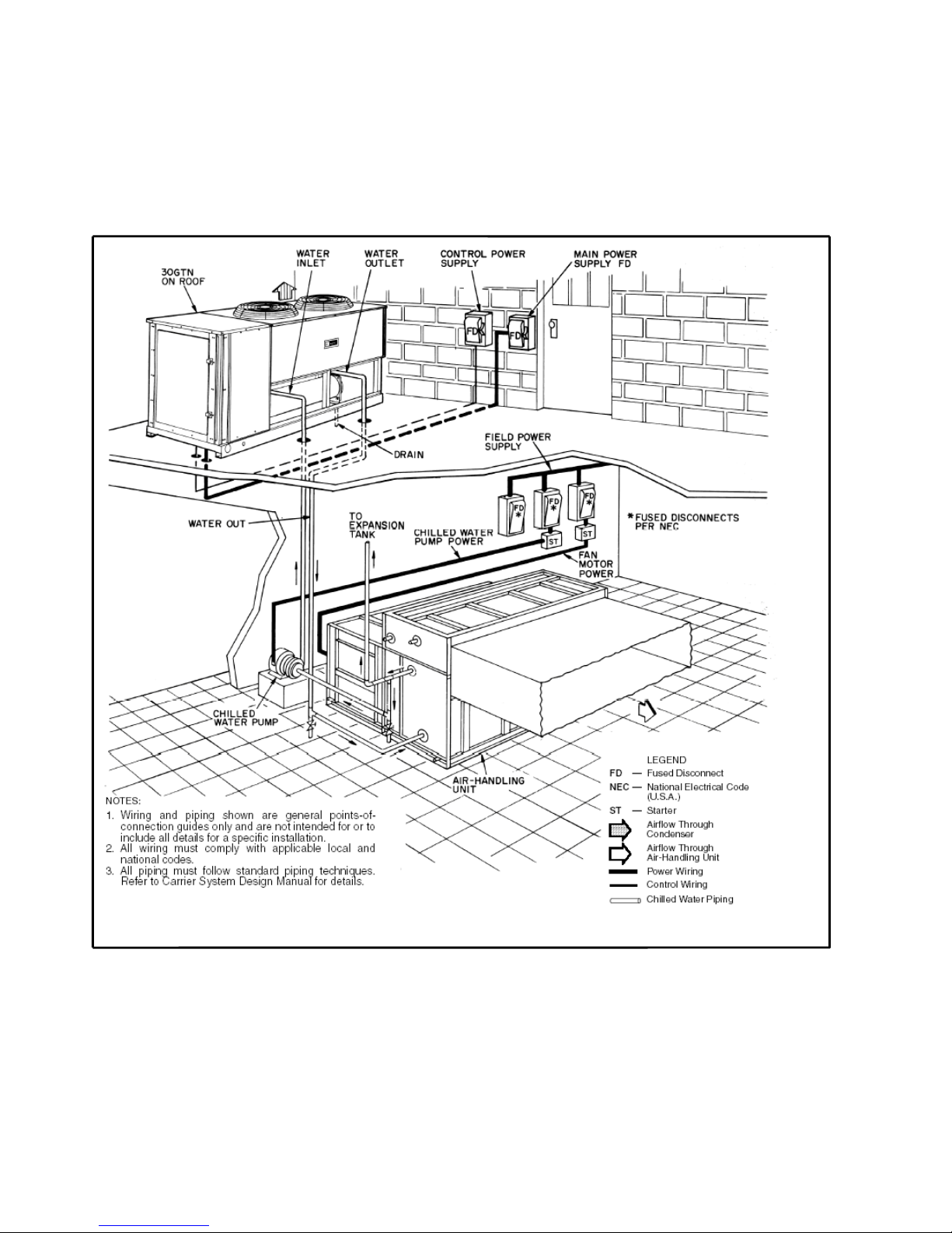
34
Typical piping and wiring — 30GTN,GTR050-110,
GBN,GBR150-200
Page 35
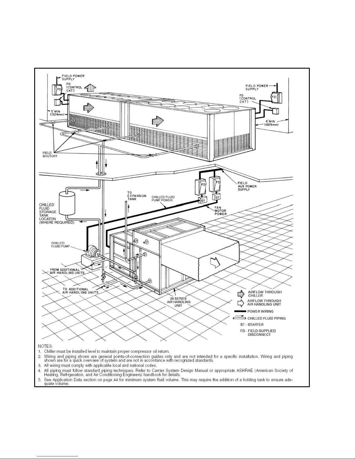
35
Typical piping and wiring — 30GBN,GBR300-400
Page 36

36
Guide specifications
Reciprocating Air-Cooled Liquid Chiller
HVAC Guide Specifications
Size Range: 50 to 400 Tons (176 to 1408 kW) Nominal
Carrier Model Number: 30GTN,GTR,GBN,GBR
Part 1 — General
1.01 SYSTEM DESCRIPTION
Easy-to-use, microprocessor-controlled air-cooled
liquid chiller utilizing reciprocating compressors and
long-stroke electronic expansion valves.
1.02 QUALITY ASSURANCE
A. Unit shall be manufactured in a facility
registered to ISO 9001 (International Standards
Organization) manufacturing quality standard.
E. Unit operation shall be fully tested at the factory.
1.03 DELIVERY, STORAGE, AND HANDLING
A. Unit shall be stored and handled per unit
manufacturer’s recommendations.
B. Unit controls shall be capable of withstanding
150 F (66 C) storage temperature in the control
compartment for an indefinite period of time.
Part 2 — Products
2.01 EQUIPMENT
A. General:
Factory-assembled, single piece, air-cooled
liquid chiller. Contained within the unit cabinet
shall be all factory wiring, piping, controls,
refrigerant charge (R-22), and special features
required prior to field start-up.
B. Unit Cabinet:
1. Frame shall be of heavy-gage galvanized steel
members.
2. Cabinet shall be galvanized steel casing with a
pre-painted finish.
3. Cabinet shall be capable of withstanding
500-hour salt spray test in accordance with the
ASTM B-117 standard.
C. Fans:
Condenser fans shall be direct-driven propeller
type discharging air vertically upward and shall be
equipped with the following features:
1. Permanently lubricated bearings.
2. Steel wire safety guards.
3. Statically and dynamically balanced fan blades.
D. Compressors:
1. Reciprocating semi-hermetic type only.
2. Each equipped with an automatically-reversible
oil pump, operating oil charge, suction and
discharge shutoff valves, and an insert-type
factory-sized crankcase heater to control oil
dilution.
3. Each mounted on spring vibration isolators
with an isolation efficiency of no less than
95%.
4. Speed shall not exceed 1750 rpm (29.2 r/s).
5. Cycles per hour per compressor shall not
exceed 6.
E. Cooler:
1. Shell-and-tube type with removable heads.
2. Tubes shall be internally enhanced seamless-copper
type rolled into tube sheets.
3. Equipped with flange type fluid connections.
4. Shell shall be insulated with
3/4-in. (19-mm) PVC
foam (closed-cell) with a maximum K factor of
0.28.
5. Design shall incorporate 2 independent direct expansion refrigerant circuits.
6. Cooler shall be tested and stamped in accordance
with ASME Code for a refrigerant working side
pressure of 278 psig (1916 kPa).
Cooler shall have a maximum fluid-side pressure
of 300 psig (2068 kPa).
F. Condenser:
1. Coil shall be air-cooled with integral subcooler,
constructed of aluminum fins mechanically bonded
to seamless copper tubes which are then cleaned,
dehydrated, and sealed.
2. Air-cooled condenser coils shall be leak tested at
150 psig (1034 kPa) and pressure tested at 450 psig
(3103 kPa).
G. Refrigeration Components:
Refrigerant circuit components shall include hot gas
muffler, high side pressure sw itch, liquid line shutoff
valves, suction and discharge shutoff valves, filter
drier, moisture-indicating sight glass, stepper motor
actuated electronic expansion valve (EXV) or
thermostatic expansion valve (TXV), and complete
operating charge of refrigerant R-22 and compressor
oil.
H. Controls, Safeties, and Diagnostics:
1. Controls:
a. Unit controls shall include the following
minimum components:
1) Microprocessor.
2) Power and control circuit terminal blocks.
3) ON/OFF control switch.
4) Replaceable solid-state relay panel.
5) Clear language, expandable, alpha numeric
diagnostic display/set point panel.
6) Thermistor installed to measure saturated
condensing temperature, cooler saturation
temperature, compressor return gas
temperature, and cooler entering and
leaving fluid temperatures.
b. Unit controls shall be capable of performing
the following functions:
1) Automatic circuit lead/lag (accessory
required for 040-070 sizes).
2) Pumpout at beginning and end of every
circuit cycle.
3) Capacity control based on leaving chilled fluid
temperature and compensated by rate of
change of return-fluid temperature.
4) Limiting of the chilled fluid temperature
pulldown rate at start-up to 1° F (.56° C) per
minute to prevent excessive demand spikes
(charges) at start-up.
5) Seven-day time schedule.
6) Leaving chilled fluid temperature reset from
return fluid, outdoor-air temperature, space
temperature, or 4 to 20 mA input.
7) Demand limit control with 2-stage control (0
to 100% each) or through 4 to 20 mA input (0
to 100%).
Page 37

37
2. Safeties:
a. Unit shall be equipped with thermistors and all
necessary components in conjunction with the
control system to provide the unit with the
following protections:
1) Loss of refrigerant charge protection.
2) Low fluid flow detection.
3) Low chilled fluid temperature protection.
4) Low and high superheat protection.
5) Low control voltage (to unit) protection.
6) High-pressure switch.
7) Low oil protection for each compressor circuit
8) Ground current compressor protection.
b. Compressors shall be equipped with the following
manual-reset type protections:
1) Pressure overload.
2) Electrical overload through the use of definite purpose contactors and calibrated, ambient
compensated, magnetic trip circuit breakers.
Circuit breakers shall open all 3 phases in the
event of an overload in any one phase (single phasing condition).
c. Fan motors shall have inherent overcurrent
protection.
3. Diagnostics:
a. The diagnostic display module shall be capable
of indicating the safety lockout condition by
displaying a code for which an explanation may
be scrolled at the display. Information included
for display shall be:
1) Compressor lockout.
2) Loss of charge.
3) Low fluid flow.
4) Low oil pressure.
5) Cooler freeze protection.
6) High or low suction superheat.
7) Thermistor malfunction.
8) Entering and leaving-fluid temperature.
9) Evaporator and condenser pressu re.
10) Electronic expansion valve positions.
11) All set points.
12) Time of day.
b. Display module, in co njunction with the
microprocessor, must also be capable of
displaying the output (results) of a service test.
Service test shall verify operation of every
switch, thermistor, fan, and compressor before
chiller is started.
I. Operating Characteristics:
1. Unit shall be capable of starting and running fully
loaded at outdoor ambient temperatures from 0° F
to 125 F (–18 to 52 C), without special controls.
2. Unit shall be capable of starting up with 95 F (35
C) entering-fluid temperature to the cooler.
3. Multi-step cooling capacity control shall be
accomplished through the use of unloaders and
compressor staging.
4. Two refrigerant circuits shall be provided to
protect against loss of total capacity.
5. Unit shall have automatic lead/lag feature to
automatically alternate the lead circuit to ensure
even compressor wear.
J. Motors:
1. Compressor motors shall be cooled by suction gas
passing around motor windings.
2. Condenser-fan motors shall be 3-phase type with
permanently lubricated bearings and Class B
insulation.
3. Fan motors are totally enclosed, air-over (TEAO)
type in accordance with IP-55.
K. Electrical Requirements:
1. Unit primary electrical power supply (3-phase)
shall be connected to a single location.
2. Unit control power (single-phase) shall be
connected to a separate entry point.
3. Unit shall be shipped with factory control and
power wiring installed.
Page 38

38
Manufacturer reserves the right to discontinue, or change at any time, specifications or designs without notice and without incurring obligations.
Carrier International Sdn. Bhd., Malaysia
A
United Technologies Compan
y
Carrier
 Loading...