

Page 1
Refrigerant Management System
Installation, Operating and Maintenance
Instructions
For Use With Low-Pressure Centrifugal Liquid Chillers
SAFETY CONSIDERATIONS
Refrigerant recovery devices are designed to provide safe
and reliable service when operated within design spec
ifications. When operating this equipment, use good judg
ment and safety precautions to avoid damage to equip
ment and property or injury to personnel.
Be sure you understand and follow the procedures and
safety precautions contained in this guide.
A DANGER
DO NOT VENT refrigerant relief valves within a building. Outlet
from rupture disc or relief valve must be vented outdoors in ac
cordance with the latest edition of ASHRAE 15 (Safety Code for
Mechanical Refrigeration). The accumulation of refrigerant in an
enclosed space can displace oxygen and cause asphyxiation.
PROVIDE adequate ventilation in accordance with ASHRAE 15,
especially for enclosed and low overhead spaces. Inhalation of
high concentrations of vapor is harmful and may cause heart ir
regularities, unconsciousness, or death. Misuse can be fatal. Va
por is heavier than air and reduces the amount of oxygen available
for breathing. Product causes eye and skin irritation. Decomposi
tion products are hazardous.
DO NOT USE OXYGEN to purge lines or to pressurize a ma
chine for any purpose. Oxygen gas reacts violently with oil, grease,
and other common substances.
NEVER EXCEED specified test pressures, VERIFY the allow
able test pressure by checking the instruction literature and the de
sign pressures on the equipment nameplate.
DO NOT USE air for leak testing. Use only tracer gases and dry
nitrogen.
DO NOT VALVE OFF any safety device.
BE SURE that all pressure relief devices are properly installed
and functioning before operating any machine.
A WARNING
DO NOT WELD OR FLAMECUT any refrigerant line or vessel
until all refrigerant (liquid and vapor) has been removed from chiller.
Traces of vapor should be displaced with dry air or nitrogen and
the work area should be well ventilated.
with an open flame produces toxic gases.
DO NOT USE eyebolts or eyebolt holes to rig machine sections
or the entire assembly.
DO NOT work on high-voltage equipment unless you are a qual
ified electrician.
DO NOT WORK ON electrical components, including control pan
els, switches, starters, or oil heater until you are sure ALL POWER
IS OFF and no residual voltage can leak from capacitors or solidstate components.
LOCK OPEN AND TAG electrical circuits during servicing. IF
WORK IS INTERRUPTED, confirm that all circuits are de
energized before resuming work.
DO NOT siphon refrigerant by mouth.
AVOID SPILLING liquid refrigerant on skin or getting it into the
eyes. USE SAFETY GOGGLES. Wash any spills from the skin
Refrigerant in contact
with soap and water. If any enters the eyes, IMMEDIATELY FLUSH
EYES with water and consult a physician.
NEVER APPLY an open flame or live steam to a refrigerant cyl
inder. Dangerous overpressure can result. When necessary to heat
refrigerant, use only warm (110 F [43 C]) water,
DO NOT REUSE disposable (nonreturnable) cylinders or
attempt to refill them. It is DANGEROUS AND ILLEGAL. When
cylinder is emptied, evacuate remaining gas pressure, loosen
the collar and unscrew and discard the valve stem. DO NOT
INCINERATE.
CHECK THE REFRIGERANT TYPE before adding refrigerant
to the machine. The introduction of the wrong refrigerant can cause
damage or malfunction to this machine.
Operation of this equipment with refrigerants other than those
cited herein should comply with ASHRAE-15 (latest edition). Con
tact Carrier for further information on use of this machine with
other refrigerants.
DO NOT ATTEMPT TO REMOVE fittings, covers, etc., while
machine is under pressure or while machine is running. Be sure
pressure is at 0 psig (0 kPa) before breaking any refrigerant
connection.
CAREFULLY INSPECT all relief devices, rupture discs, and other
relief devices AT LEAST ONCE A YEAR. If machine operates
in a corrosive atmosphere, inspect the devices at more frequent
intervals.
DO NOT ATTEMPT TO REPAIR OR RECONDITION any re
lief device when corrosion or build-up of foreign material (rust,
dirt, scale, etc.) is found within the valve body or mechanism.
Replace the device.
DO NOT install relief devices in series or backwards.
USE CARE when working near or in line with a compressed spring.
Sudden release of the spring can cause it and objects in its path to
act as projectiles.
A CAUTION
DO NOT STEP on refrigerant lines. Broken lines can whip about
and cause personal injury.
DO NOT climb over a machine. Use platform, catwalk, or stag
ing. Follow safe practices when using ladders.
USE MECHANICAL EQUIPMENT (crane, hoist, etc.) to lift or
move inspection covers or other heavy components. Even if com
ponents are light, use such equipment when there is a risk of slip
ping or losing your balance.
BE AWARE that certain automatic start arrangements CAN EN
GAGE THE STARTER. Open the disconnect ahead of the starter
in addition to shutting off the machine or pump.
USE only repair or replacement parts that meet the code require
ments of the original equipment.
DOUBLE-CHECK that coupling nut wrenches, dial indicators, or
other items have been removed before rotating any shafts.
DO NOT LOOSEN a packing gland nut before checking that the
nut has a positive thread engagement.
PERIODICALLY INSPECT all valves, fittings, and piping for
corrosion, rust, leaks, or damage.
19QA
50/60 Hz
Manufacturer reserves the right to discontinue, or change at any time, specifications or designs without notice and without incurring obligations.
Book|2 |2 PC 221 Catalog No 531-963 Printed in U S A Form 19QA-2SI Pg 1 9-94 Replaces: 19QA-1 SI
Tab |5a|5d
Page 2

CONTENTS
Page
SAFETY CONSIDERATIONS
INTRODUCTION
.........................................................
.....................................
INSTALLATION ..........................................................2-7
Complete Pre-Installation Checks............................2
• IDENTIFY UNIT
• INSPECT SHIPMENT
Make Piping Connections
Make Electrical Connections
Optional Caster Installation
CONTROLS AND COMPONENTS
.........................................
....................................
......................................
.............................
7,8
Pump and Motor .........................................................7
Oil Separator...............................................................7
Heater ..........................................................................7
Tube-in-Tube Condenser...........................................7
Level Gage ..................................................................7
Water Separation Sight Glass
Purge Separator Assembly
..................................
.......................................
7
Refrigerant Hoses ......................................................8
Liquid Indicator
..........................................................
8
Filter Drier ...................................................................8
OPERATION .............................................................9-14
Evacuation ..................................................................9
Liquid Refrigerant Transfer.......................................9
• BEFORE TRANSFERRING LIQUID
REFRIGERANT
• TO TRANSFER LIQUID REFRIGERANT
Refrigerant Vapor Transfer
• BEFORE TRANSFERRING REFRIGERANT
VAPOR
• TRANSFER REFRIGERANT
......................................
10
Purge Separator Assembly ......................................12
Oil Separation ............................................................12
Water Separation .......................................................13
MAINTENANCE
Maintaining the Pump
Pump Coupling
High-Pressure Cutout Switches
.........................................................
..............................................
.........................................................
..............................
15
15
15
15
Refrigerant Storage Tank.........................................15
Refrigerant Hoses
.....................................................
15
TROUBLESHOOTING................................................16
Table 1 — Interconnecting Refrigerant Hoses,
Valves, and Fittings
NUMBER
1
2
2
2
2
1
2
1 KA73PS012
1 19QA020-152 Liquid Indicator
8
1 19QA015-142
NOTE: Refer to Fig. 1 for model number description and accessory
caster package part numbers.
PART NUMBER PART
KA73PS003 3 ft (.91 m) Hose
KA73PS006 6 ft (1.88 m) Hose
12 ft (3.66 m) hose
19QA020-132 Valve and Coupler
Chiller Vapor Valve
INSTALLATION
Complete Pre-Installation Checks
IDENTIFY UNIT — Identify the model number and serial
number printed on the nameplate. Check this information
against the job requirements.
7
INSPECT SHIPMENT — Inspect unit for damage before
removing unit from shipping conveyance. If unit appears
damaged, it should be inspected by a shipping inspector be
fore removal. File claim with shipping company if ship
ment is damaged or incomplete. The manufacturer is not
responsible for damage incurred during transit.
Check all components. Notify the supplier immediately
if any item is missing. To prevent loss or damage, leave all
parts in their original package until they are needed.
Make Piping Connections — All connections be
tween the pump, tube-in-tube condenser, storage tank, and
chiller can be made using the factory supplied refrigerant
hoses. A hand valve with coupler is factory supplied, but
must be field installed at each end of the 4 hoses. See
Fig. 5. Field supplied copper tubing and valve manifolds
must be used if a permanent installation is required.
The 19QA is factory equipped with a dual relief valve
assembly. See Fig. 4. The outlet of the valves is 1-1/2 in.
MPT. Vent the dual relief assembly outdoors in accordance
with ASHRAE 15 (Safety Code for Mechanical Refrigera
tion), latest edition, and all applicable local codes. Use a
minimum 1-1/2 in. pipe for the relief valve outlet. Provide
fittings so vent piping can be disconnected periodically for
inspection and testing of valves.
Cover the outdoor vent with a rain cap and place a field
supplied condensate drain at the low point in vent piping to
prevent water build up on the atmospheric side of the valve.
INTRODUCTION
The 19QA Refrigerant Management System (RMS) has
been designed to help owners and operators of centrifugal
chillers conserve low pressure refrigerants and prevent the
release of excessive amounts of refrigerant into the atmo
sphere. The proper use of this equipment will minimize the
loss of CFCs and HCFCs. The 19QA will also recycle re
frigerant contaminated with water, oil, or acid. See Fig. 1
and Table 1 for component information.
The 19QA is ARI (Air Conditioning & Refrigeration In
stitute) certified as a refrigerant recovery/recycling device
and is registered with ETL (Electrical Testing Laboratory)
for safety. The Refrigerant Management System’s storage
tanks are rated for 20, 30, or 40 cu ft (.57, .85, 1.13 cu
meters). See Table 2. Casters are available as an option on
all storage tanks. See Fig. 1-3. See Fig. 4 and 5 for addi
tional RMS component descriptions and dimensions.
Make Electrical Connections — The 19QA has 2
electrical cords. See Table 3 and Fig. 6. One electrical cord
is attached to the pump and the other is attached to the stor
age tank heater. If both electrical cords are used at the same
time, separate outlets are required. Connect electrical power
in accordance with minimum circuit amps (MCA) and max
imum overcurrent protection amps (MOCP) as specified on
the unit nameplate. Be sure that the unit is connected and
grounded in accordance with all applicable electrical codes.
Optional Caster Installation — if optional casters
have been provided, bolt the 4 caster assemblies to the stor
age tank. See Fig. 1-3. Size 020 and 030 storage tanks have
2 rigid casters mounted on one end of the tank and 2 swivel
casters with brakes mounted on the other end of the storage
tank. The size 040 storage tanks have 2 swivel casters with
brakes mounted on one end of the storage tank and 2 swivel
casters with locks mounted on the other end of the storage
tank.
Page 3
Table 2 — Physical Data
19QA
DRY WEIGHT OF RMS
DRY WEIGHT OF RST
TANK SIZE
TANK STORAGE CAPACITY
CFC-11 Liquid
DESIGN PRESSURE
MAX. OPERATING PRESSURE
CONNECTION SIZES
HIGH-PRESSURE SWITCHES
Tank Heater and Pump
Cutout
Manual Reset
PUMP
Motor Hp
Max. Discharge Pressure
Min. Vacuum (Gage)
Flow Rate
60 Hz
50 Hz
RMS — Refrigerant Management System
RST — Refrigerant Storage Tank
ENGLISH
Size
lb 740
lb
cu ft 20 30 40
lb 1600 2450 3300
psig 15 kPa 103
psig 10 kPa 69
in. Va Flare in.
psig
psig
psig
in. Hg 29 kPa -98
cfm
020 030
841 942
495 546 586
10
<4
%
10 kPa
10.5
8.8
040
Size
kg
kg
CU m .57
kg
kPa
kPa
L/s
SI
020 030
336
225 248 266
727 1114
382
.85 1.13
У2 Flare
69
<28
%
69
4.96
4.16
040
428
1500
19QA - 020 - 2 74
19QA
Size
020 — 20 cu ft (.57 cu meters)
030 — 30 cu ft (.85 cu meters)
040 — 40 cu ft (1.13 cu meters)
- Refrigerant
Management
System
NOTE: Accessory caster packages are avaiiabie for use with the
19QA. Refer to the following table for specific part numbers.
ACCESSORY CASTER
PACKAGE PART NUMBER
19QA 020 213 020
19QA 030 213
19QA 040 213
RMS — Refrigerant Management System
RST — Refrigerant Storage Tank
Fig. 1 — Model Number Description
74 — Refrigerant Management
System
84 — Refrigerant Storage Tank
V-Ph-Hz
2 — 115-1-50/60
3 — 230-1-50/60
RMS/RST SIZE
030
040
Page 4
UNIT
SIZE
19QA020
19QA030
19QA040
A B
4'-9"
[1448]
7'-3"
[2209]
Q'-Q"
[2972]
5'-4%''
[1648]
7'-10%"
[2410]
10'-4%"
[3172]
NOTE: Dimensions in [ ] are in mm.
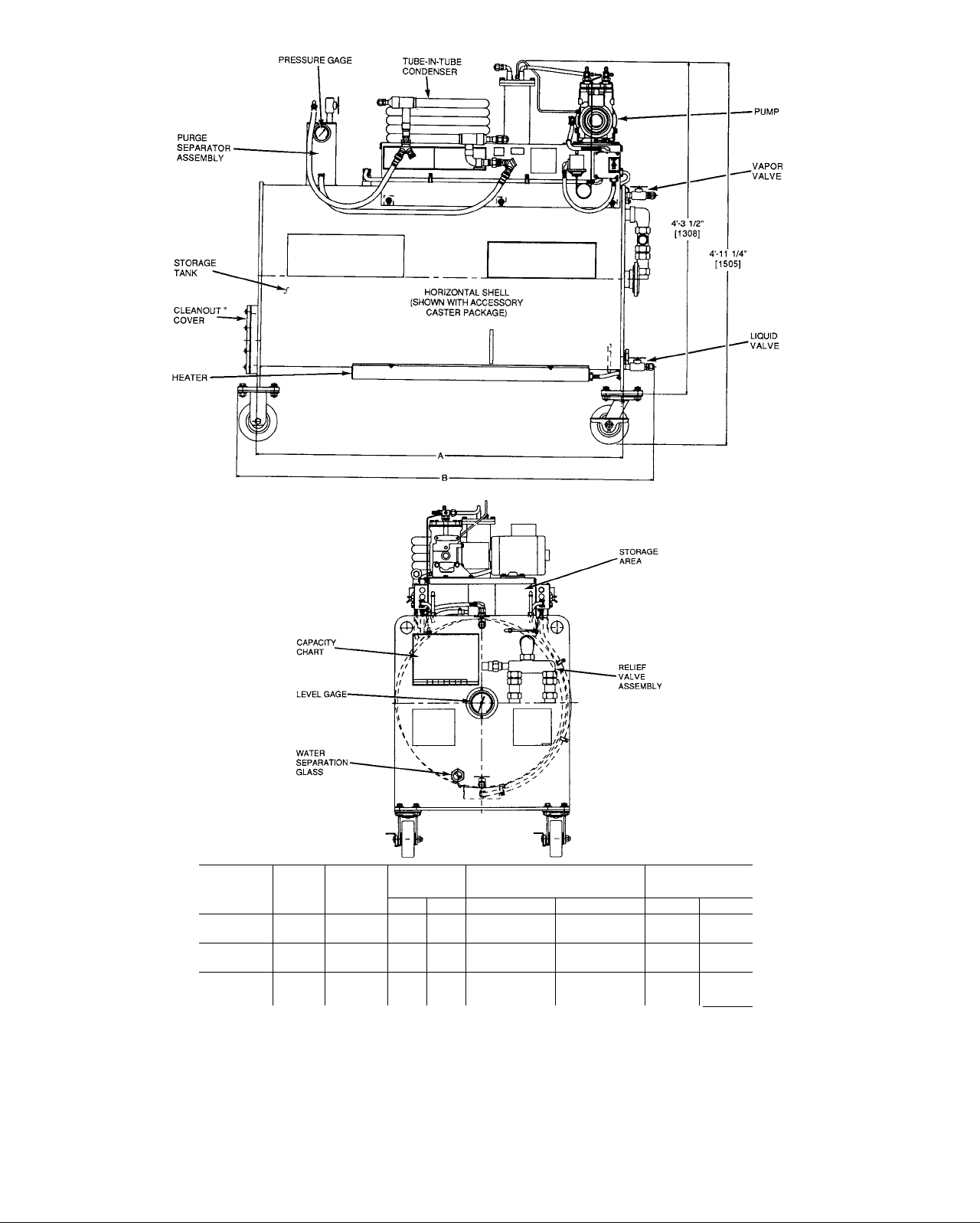
Fig. 2 — 19QA Refrigerant Management System Dimensions
WEIGHT
EMPTY
MAXIMUM REFRIGERANT
lbs kg lbs
740 336 1600
841 382 2450
942 428 3300
CHARGE
ACCESSORY
CASTERS
kg
727 34 15
1114 48
1500
lbs kg
62 28
22
Page 5

PRESSURE GAGE
VAPOR
VALVE
UNIT
SIZE
19QA020
19QA030
19QA040
A
4'-9"
[1448]
7'-3"
[2209]
Q'.Q"
[2972]
B
5'-4%"
[1648]
7'-10%”
[2410]
10'-4%"
[3172]
NOTE: Dimensions in [ ] are in mm.
WEIGHT
EMPTY
lbs
495 225 1600 727
546 248 2450 1114
586 266
MAXIMUM REFRIGERANT
kg
lbs kg
3300 1500 62
CHARGE
RELIEF
-VALVE
ASSEMBLY
■ LEVEL GAGE
ACCESSORY
CASTERS
lbs
34 15
48 22
kg
28
Fig. 3 — 19QA Refrigerant Storage Tank Dimensions
Page 6

NO. ITEM NO.
1 — Pressure Gage 12 —
2 — Purge Separator Assembly
3 — Refrigerant (Vapor) In 13 —
4 — Tube-in-Tube Condenser 14 —
5 — Filter Drier Vi SAE Flare (Hidden)
6 — Refrigerant (Liquid) Out
7 — Oil Separator
8 — Pump
9 — Pump Motor
10 — Heater High-Pressure
11 — Heater ON/OFF Switch (Hidden) 15 —
Cutout Switch (Hidden)
Fig. 4 — 19QA Refrigerant Management System Components
ITEM
Pump High-Pressure
Cutout Switch
Pump ON/OFF Switch
Storage Area
Components Included:
Refrigerant Hose, 3 ft
Refrigerant Hose, 6 ft (2)
Refrigerant Hose, 12 ft
Valve With Coupler (8)
Chiller Vapor Valve
Liquid Indicator With Coupler
Vapor Valve
NO. ITEM
16 — Refrigerant Capacity Chart
17 — Relief Valve Assembly
18 — Level Gage
19 — Liquid Valve
20 — Accessory Casters
21 — Water Separation Sight Glass
22 — Heater With Cover
23 — Storage Tank
24 — Water In
25 — Water Out
(Available On All Tank Sizes)
Table 3 — Electrical Data
Fig. 5 — Interconnecting Refrigerant Hoses,
Valves, and Fittings
VOLTS-PH-HZ 115-1-50
PUMP MOTOR
Hp 3/4
Amps 9.6 8.6 4.8 4.3
MCA
HEATER
Amps
MCA 12 12 11 11
MOCP 15* 15*
MCA — Minimum Circuit Amps
MOCP — Maximum Overcurrent Protection (Amps)
*Two circuits required for simultaneous operation.
NOTE: Use time-delay fuses.
10
12 12 6
LEGEND
115-1-60 230-1-50
3/4
10
3/4 3/4
5 5
15
230-1-60
6
15
Page 7

HUiH LEVEL
SWITCH
L2
MOTOR WIRING SCHEMATIC
Ll
TOGGLE
SWITCH
NOTE; The 115 and 230 v control wiring are identicai.
PRESSURE
SWITCH
HEATER WIRING SCHEMATIC
Fig. 6 — Typical Control Wiring Schematic
CONTROLS AND COMPONENTS
Pump and Motor — The pump is designed for vac
uum and pressure duty. The pump is splash lubricated and
operates in conjunction with an oil separator. It is directly
coupled to and driven by a 3/4-hp motor. The coupling be
tween the pump and motor has a rubber insert to compen
sate for slight misalignment. Start and stop the pump by
using the toggle switch located next to the pump. A tank
pressure switch set at 10 psig (69 kPa) and a tank level
switch set 90% full will shut off the pump if either limit is
reached. See Table 1 for additional information on the pump
and motor.
Oil Separator — The oil separator removes the oil that
is mixed with the discharge gas leaving the pump. The dif
ferential pressure between the oil separator and the pump
crankcase returns the oil to the pump through the float valve
in the oil separator when the specified oil level is achieved
in the oil separator.
Heater — A 1500 watt, etched-foil, electric heater is at
tached to the bottom of the storage tank. See Fig. 2. The
heater is encased in an insulated protective cover and is con
trolled by a toggle switch.
Use the heater when refrigerant recycling by distillation
is necessary. When the heater toggle switch is in the ON
position, the indicating light, located next to the toggle switch,
will be lit. A pressure switch will shut off the heater if the
tank pressure reaches 10 psig (69 kPa) when heating
refrigerant.
L2
-ORN-
-WHT
---^-------
HEATER
——
LAMP
WHT-
Tube-in-Tube Condenser — A tube-in-tube con
denser allows refrigerant vapor to be condensed when re
moving vapor from a chiller or when distilling refrigerant.
Garden hose connections (3/4 in.) are provided for condens
ing water. Condensing water temperature should be as low
as possible to minimize the time required to complete an
operation. A water flow rate of 2 gpm (.012 L/s) at 70 F
(21 C) is normally adequate.
Level Gage — A geared, float level gage displays the
storage tank’s percentage of full capacity of liquid refrig
erant. The actual level of refrigerant will vary based upon
temperature and the type of refrigerant used. See Fig. 4
and 7.
Water Separation Sight Glass — A water separa
tion sight glass is located above the liquid valve. Use the
water separation sight glass to view the refrigerant/water
interface when separating water from the refrigerant. See
Fig. 4.
Purge Separator Assembly — Use the manual hand
valve on the purge separator assembly to remove noncon
densable gases that may accumulate in the storage tank dur
ing vapor recovery. The purge separator assembly contains
a water coil, 1/16-in. orifice, and 1/2-in. ball valve. The
bottom of the purge separator assembly opens into the stor
age tank. See Fig. 8.
Page 8

CFC-11 or HCFC-123
CFC-113
Ib(Kg)
This graph is based on 70 F The following multipliers may be used to more accurately determine weights at temperatures
other than 70 F
TEMPERATURE F (C)
MULTIPLIER
40 (4.4)
1 026
50 (10) 60 (15 5)
1 018
1 009 1 000
70 (21,1)
80 (26.6) 90 (32 2) 100 (37 7)
991 982
973
Fig. 7 — Storage Tank Capacity
Refrigerant Hoses — Four, l/2-in. refrigerant hoses
and 8 ball valves with couplers are factory supplied with
the RMS unit. See Table 1. The refrigerant hoses are used
to transfer liquid and vapor through the Refrigerant Man
agement System. They are designed to withstand high vac
uum pressure without collapsing.
When used with the refrigerant hoses, the ball valve and
coupler assembly prevent refrigerant loss. Connect the ball
valve and coupler assembly to each end of the 4 refrigerant
hoses. Hand tighten the ball valve and coupler assembly to
the refrigerant hose. The ball valve and coupler assembly
connect to the RMS unit or chiller, depending upon the type
of operation. The coupler should be hand tightened to the
RMS unit or chiller. Excessive tightening will damage the
rubber gaskets.
Liquid Indicator — The 1/2 in. liquid indicator (in line
sight glass) is factory supplied. Use the liquid indicator dur
ing either the liquid refrigerant transfer or the vapor con
densing process to determine the end point of the process.
When liquid is no longer visible in the glass, the process is
almost complete.
Filter Drier — The filter drier should be used to recycle
refrigerant. Use the factory supplied filter drier when re
moving moisture and small particles from the refrigerant.
The filter drier is most effective when used with liquid re
frigerant. The filter drier holds approximately .39 oz
(11 g) of water. See Table 4.
When cleaning large quantities of saturated refrigerant,
use a field supplied, replaceable core filter drier assembly.
The assembly should have four, 100 in.^ cores. It will re
move approximately 4.2 oz (118 g) of water.
WATER OUT
WATER IN
NOTE: [ ] indicates millimeters
Fig. 8 — Purge Separator Assembly
Table 4 — Water Solubility In Refrigerant
SOLUBILITY
REFRIGERANT
TYPE
CFC-11,
CFC-113,
[HCFC-123]
LEGEND
ppm — Parts Per Million
TEMPERATURE
60 F 70 32
(16 C) [660]
70 F
(21 C) [770]
80 F
(27 C) [900]
90 F 140 64
(32 C) [1000]
OF WATER IN
REFRIGERANT
(ppm)
90
113 51 1 80
NOTE: [ ] indicates HCFC-123 refrigerant
GRAMS OF
WATER
PER
1000 LB
[303] [10.7]
41
[349] [12.3]
[408]
[453] [16 0]
OZ
1.13
1.15
[14.4]
2.26
Page 9

OPERATION
Evacuation — To minimize refrigerant loss, air must
not be allowed to mix with the refrigerant vapor. All spaces
that could contain refrigerant (such as chillers, storage tanks,
and refrigerant hoses) must be completely evacuated before
charging the RMS with refrigerant.
To evacuate air from the storage tank or chiller, connect
the suction service valve of the pump to a vapor valve on
the storage tank or chiller using the shortest possible 1/2-in.
diameter refrigerant hose. Use of hoses or fittings smaller
than 1/2 in. diameter will greatly increase the time required
to pull a complete vacuum of 29 in. Hg (25 mm Hg abso
lute). Refer to Table 5 for additional information. See
Fig. 9.
Once the connections are made, turn on the pump and
discharge the air into the atmosphere.
■ — Tank Size — 20 cu ft (.57 cu meters)
NOTE: A 29 in. Hg vacuum (25 mm Hg absolute) may be obtained
at a rate of approximateiy 1 minute per cu ft of volume.
Typical 400 Ton Chiller
Fig. 9 — Evacuation of Chiller and Storage Tank
Liquid Refrigerant Transfer
A CAUTION
To prevent release of refrigerant from the dual relief
valve assembly due to expansion, the storage tank must
not be filled above 90% full at 90 F (32 C).
The storage tank is 90% full when the level gage is read
ing 100%. See Fig. 7.
BEFORE TRANSFERRING LIQUID REFRIGERANT Before using the pump for liquid or vapor transfer, run the
pump using air only for approximately 15 minutes. Run
ning the pump on air will allow it to achieve a normal op
erating temperature of 120 F (49 C). If refrigerant is used
when the pump is cold, excessive amounts of refrigerant
will be absorbed into the oil, causing dilution of the oil.
This condition may cause oil loss and shorten the life of the
pump.
A WARNING
Do not connect the pump suction service valve directly
to a liquid refrigerant source. Liquid refrigerant will
cause damage to the pump.
Use the same process when transferring liquid refrigerant
from the chiller to the storage tank or from the storage tank
to the chiller. Completely evacuate any vessel that will have
refrigerant transferred to it.
A WARNING
Do not transfer liquid refrigerant into an evacuated chiller
that contains water in the cooler tubes. Freezing water
will cause the cooler tubes to rupture.
NOTE: Make sure the ball valve and coupler assembly are
connected to all refrigerant hoses.
Prior to transferring liquid refrigerant from the storage
vessel to the chiller, make sure all water is completely drained
from the cooler tubes or raise the chiller pressure by using
refrigerant gas (24 in. Hg [ — 81 kPa] for CFC-113,
18 in. Hg [-61 kPa] for HCFC-123, and 15 in. Hg
[-51 kPa] for CFC-11).
TO TRANSFER LIQUID REFRIGERANT
Storage Tank to Chiller — To transfer liquid refrigerant from
the storage tank to the chiller, connect a 6-ft refrigerant hose
from the liquid valve on the storage tank to the chiller charg
ing valve. Install the liquid indicator on the refrigerant hose.
See Fig. 10. Connect a 12-ft refrigerant hose to the vapor
service valve on the chiller and the suction service valve on
the pump. Copper tubing is factory installed from the pump
to the oil separator. Connect another 6-ft refrigerant hose
from the discharge connection on the oil separator to the
vapor valve on the storage tank. Open the liquid valve on
the storage tank, the charging valve on the chiller, and the
two interconnecting hose valves.
Once liquid refrigerant enters the chiller, open the chiller
vapor valve, the storage tank vapor valve, all valves be
tween the chiller vapor valve and the storage tank vapor
valve. Turn on the pump. The pump will remove refriger
ant gas from the chiller and discharge it into the storage
tank. This will create a pressure differential between the
chiller and the storage tank and provide the specified flow
rate.
The end of the liquid refrigerant transfer can be deter
mined by observing the liquid indicator. When liquid is no
longer visible, the transfer is complete. Close the liquid valve
on the chiller and turn off the pump.
Chiller to Storage Tank — To transfer liquid refrigerant from
the chiller to the storage tank, connect a 6-ft refrigerant hose
from the storage tank liquid valve to the chiller charging
valve. Install the liquid indicator to determine when liquid
transfer is complete. Connect a 12-ft refrigerant hose to the
vapor service valve on the chiller and the suction service
valve on the pump. Copper tubing is factory installed from
the pump to the oil separator. Connect another 6-ft refrig
erant hose from the discharge connection on the oil sepa
rator to the vapor valve on the chiller. Open the charging
valve on the chiller, the liquid valve on the storage tank,
and the two interconnecting hose valves.
Once liquid refrigerant enters the storage tank, open the
storage tank vapor valve, chiller vapor valve, and all valves
between the storage tank vapor valve and chiller vapor valve.
Turn on the pump. The pump will remove refrigerant gas
from the storage tank and discharge it into the chiller. This
will create a pressure differential between the storage tank
and provide the specified flow rate.
The end of the liquid refrigerant transfer can be deter
mined by observing the liquid indicator. When liquid is no
longer visible, the transfer is complete. Close the bottom
valve on the chiller and turn off the pump.
Page 10

Refrigerant Vapor Transfer
A WARNING
If the required vacuum level cannot be reached due to
the presence of a large leak in the chiller, the vapor
recovery process should be stopped. The constant in
filtration of air into the chiller may contaminate the
refrigerant.
Refrigerant vapor recovery is required after the liquid re
frigerant has been removed. Most refrigerant vapor can be
recovered by evacuating the chiller or storage tank and con
densing the vapor. The United States EPA requires the evac
uation level for low pressure chillers to be 29 in. Hg
(25 mm Hg absolute). Refer to Table 5 for additional
information.
Before using the pump for vapor recovery, make sure it
is at the correct operating temperature of 120 F (49 C). This
can be achieved by running the pump on air only for ap
proximately 15 minutes. If the pump is operating below op
erating temperature with refrigerant, excessive amounts of
refrigerant will be absorbed into the oil, causing dilution of
the oil. This condition may cause reduced vacuum capabil
ity and may shorten the life of the pump.
NOTE: If oil dilution is affecting the pump’s ability to achieve
29 in. Hg (25 mm Hg absolute), an oil change may be re
quired. See the Maintenance section on page 15.
BEFORE TRANSFERRING REFRIGERANT VAPOR When transferring refrigerant vapor from a chiller to a stor
age tank, connect the 12-ft refrigerant hose from the vapor
valve on the chiller to the suction service valve on the pump.
See Fig. 11. Copper tubing is factory installed from the
pump to the oil separator. Connect a 6-ft refrigerant hose
from the discharge connection of the oil separator to the in
let of the tube-in-tube condenser. See Fig. 4 for location.
Connect another 6-ft refrigerant hose from the refrigerant
outlet of the tube-in-tube condenser to the vapor valve on
the storage tank. See Fig. 4. Close the bottom valve on the
chiller and turn off the pump. The tube-ln-tube condenser
must be evacuated before starting this process.
The tube-in-tube condenser must be evacuated. Make sure
all refrigerant hose valves are closed. Remove the refriger
ant hose end connected to the pump suction service valve.
Remove the refrigerant hose end connected to the top valve
on the storage tank and connect it to the pump suction serv
ice valve. Close the pump discharge service valve and re
move the 1/4-in. cap on top of the pump discharge service
valve. Open all valves between the suction and discharge
service valves of the pump. Turn on the pump for about
5 seconds to evacuate the tube-in-tube condenser. The air
will be discharged through the 1/4 in. discharge port on the
pump discharge service valve. Once the evacuation is com
plete, reconnect the refrigerant hoses to their original con
nections. Replace the 1/4-in. cap on the pump discharge
service valve. Open the pump discharge service valve.
Connect a water hose to the water inlet connection (lo
cated on the bottom of the tube-in-tube condenser) and the
other water hose to the water outlet connection (located on
top of the tube-in-tube condenser). A water flow rate of ap
proximately 2 gpm (.012 L/s) is required at 70 F (21 C).
Refrigerant Hose
Direct Coupled Connection
Factory-Installed Copper Tubing
Fig. 10 — Liquid Refrigerant Transfer
(From Storage Tank to Chiller)
10
Page 11

WATER
CONNECTIONS
DISCHARGE
Refrigerant Hose
Water Hose
Direct Coupled Connection
Factory-Installed Copper Tubing
Fig. 11 — Refrigerant Vapor Transfer/Evacuation Connections
TO TRANSFER REFRIGERANT - Open all valves be
tween the chiller and storage tank. Turn on the water to the
tube-in-tube condenser. Turn on the pump. After a few min
utes, the condensed vapor will be seen in its liquid form
flowing through the liquid indicator to the storage tank. The
end of the vapor transfer can be determined by observing
the liquid indicator. When liquid is no longer visible, the
transfer is complete.
A CAUTION
Be sure to run the chiller water pumps when removing
refrigerant vapor. Trapped liquid may boil and can cause
tube freeze-up.
The vapor recovery process is complete when the vac
uum in the chiller has reached 29 in. Hg (25 mm Hg). Be
fore turning off the pump, shut off the water to the tubein-tube condenser and then drain the water from the condenser.
As the condenser warms up, it will help drain any liquid
remaining in the condenser and refrigerant hose into the stor
age tank. Turn off the pump. Close the valves to the stor
age tank and chiller. Disconnect the refrigerant hoses. Any
refrigerant vapor remaining in the refrigerant hoses and the
tube-in-tube condenser are considered to be de minimis. See
Fig. 12.
Use the same process when transferring vapor refrigerant
from the storage tank to the chiller.
10
20 30
WEIGHT (Kg OF CFC-11)
Fig. 12 — Refrigerant Vapor Remaining
in Chiller After Removal
of Liquid Refrigerant (400 Ton Unit)
40
11
Page 12

Purge Separator Assembly — A purge separator
assembly is used to remove noncondensable gases that may
be mixed with the refrigerant being recovered. See Fig. 4.
If vapor is being recovered from a leaking chiller, air will
enter the machine. The air will mix with the refrigerant gas
and collect in the storage tank. The air will raise the pres
sure of the storage tank until the pressure reaches 10 psig
(69 kPa). At this point, the high pressure cutout switch will
turn off the pump. To avoid this situation, a purge separa
tor assembly is factory installed. See Fig. 8.
During the vapor recovery process, the pressure in the
storage tank should not be higher than the corresponding
pressure/temperature relationship for a given refrigerant, based
on ambient conditions. If the room temperature is approx
imately 75 F (24 C) and CFC-11 is being recovered, the
pressure in the storage tank should be approximately 0 psig
(0 kPag). If the pressure is higher than 0 psig (0 kPag), a
noncondensable gas is present in the storage tank. See
Table 5.
A pressure gage is mounted on top of the purge separator
assembly. When the pressure reaches 8 psig (55 kPag) and
the pressure/temperature relationship shows this as exces
sive, the purge valve on top of the purge separator assem
bly should be opened to remove the noncondensable gas.
See Fig. 4. Based on the ambient temperature, the purge
separator assembly should be operated until the saturated
pressure is achieved. If the ambient temperature is 75 F
(24 C), the purge valve should be opened until the storage
tank pressure reaches 0 psig (0 kPa).
Oil Separation — The refrigerant management system
separates oil from refrigerant through distillation. The re
frigerant can be transferred from the chiller to the storage
tank and then distilled back to the chiller or another storage
tank.
Connect the 3-ft refrigerant hose from the storage tank
vapor valve to the pump suction service valve. See Fig. 13.
Copper tubing is factory installed from the pump to the oil
separator. Connect the 6-ft refrigerant hose from the oil sep
arator discharge connection to the top connection on the
tube-in-tube condenser. Connect the 12-ft refrigerant hose
with the liquid indicator to the refrigerant outlet connection
on the condenser and to the chiller charging valve or an
other storage tank. Provide water at approximately 2 gpm
(.012 L/s) and a maximum temperature of 70 F (21 C) to
the tube-in-tube condenser using suitable water hoses. Turn
on the pump and heater using the toggle switches provided.
If the distilled refrigerant is being returned to the chiller,
run cool water through the evaporator heat exchanger. Ap
proximately 1.2 lb per minute (.54 kg per minute) of CFC-11
can be distilled per hour. When liquid refrigerant is no longer
seen in the liquid indicator, the distillation process is
complete.
After the distillation process is complete, the oil remain
ing in the bottom of the storage tank should be drained us
ing the liquid valve on the storage tank. After the oil is
drained, the tank can be wiped clean by opening the access
cover located on the opposite end of the level gage.
WATER
CONNECTIONS
Refrigerant Hose
Water Hose
Direct Coupled Connection
Factory-lnstailed Copper Tubing
Fig. 13 — Oil Separation Connections
12
Page 13

Water Separation — Water is only slightly soluble in
refrigerant. See Table 4. If additional water is present, it
will float on top of the refrigerant and can be easily re
moved by the RMS unit.
Transfer the water contaminated refrigerant to the stor
age tank using the procedures described in the Liquid Re
frigerant Transfer section. If the refrigerant contamination
was caused by a chiller failure, the chiller must be repaired,
dehydrated, and vacuum broken with refrigerant. Use
24 in. Hg (-81 kPa) for CFC-113, 18 in. Hg (-61 kPa)
for HCFC-123, and 15 in. Hg (-51 kPa) for CFC-H to
avoid freezing the tubes in chiller before the cleaned liquid
refrigerant can be returned to the chiller. If the chiller is not
repaired, the clean refrigerant should be transferred to an
other clean tank.
Connect the 12-ft refrigerant hose from the chiller or clean
storage tank vapor valve to the suction service valve on the
pump. See Fig. 14. Copper tubing is factory installed from
the pump to the oil separator. Connect a 6-ft refrigerant
hose from the discharge connection of the oil separator to
the vapor valve on the storage tank. Connect the 3-ft refrig
erant hose and liquid level indicator from the liquid valve
of the storage tank to the filter drier canister. See Fig. 5.
Connect the remaining 6-ft refrigerant hose from the filter
drier canister to the chiller charging valve or the liquid valve,
if using a storage tank. Open all valves between the storage
tank and the chiller. Turn on the pump.
While the liquid refrigerant is being transferred into the
chiller or another storage tank, use the water separation glass
at the bottom of the tank to determine when the water/
refrigerant level is close to the liquid valve. See Fig. 4. Re
duce the liquid flow rate as the water level approaches the
liquid valve. Close the liquid valve when the water/
refrigerant level is at the bottom of the water separation
glass to prevent water from entering the other storage tank.
To prevent the loss of remaining refrigerant, transfer the
water/refrigerant mixture into an open container. Skim the
water off the top of the refrigerant. Transfer the remaining
refrigerant into the storage tank.
Refrigerant Hose
Direct Coupled Connection
Factory-Installed Copper Tubing
FILTER DRIER
Fig. 14 — Water Separation
13
Page 14

Table 5 — Vapor Pressure
TEMPERATURE
°F
-20
-15
-10
-5
0
5
10
15
20
25
30
35
40
45
50
55
60
65
70
75
80
85
90
95
100
105
110
115
120
125
130
135
140
145
150
NOTE: Italics indicates in. Hg vacuum.
°c
-28.9
-26.1
-23.3
-20.6
-17.8
-15.0
-12.2 23.0
-9.4
-6.7 21.0
-3.9
-1.1
-1.7
10.0
12.8
15.6
18.3
21.1
23.9
26.7
29.4
32.2
35.0
37.8
40.6
43.3
46.1
48.9
51.7
54.4
57.2
60.0
62.8
65.6
Psi
Gage
26.9
26.5
25.9
25.3
24.6
23.9
22.1 3.8
19.8
18.5
17.1
15.6
4.4
13.8 7.9
7.2
12.0
9.9
7.7 10.9
5.3
2.7
0.1
1.6
3.2
4.9
6.8
8.8
10.9
13.2 27.9 91.0
15.7 30.3 108.3
18.3
21.1
24.0
27.1
30.5 45.1 210.3
34.0
37.7
Psi kPa
Absolute Gage
1.4
1.7 -89.7 11.7
1.9
2.2 -85.7 15.2
2.6
2.9 -80.9^ 19.9
3.4 -77.9
4.3
4.9
5.6 -62.6 38.6
6.3 -57.9
7.0 -52.8 48.3
8.8
9.8 -33.5 67.6
12.0 -17.9
13.4 -9.1
14.7
16.2
17.9
19.6 33.8
21.5
23.5 60.7 162.0
25.6 75.2
32.9 126.2
35.7
38.7 165.5
41.8
48.6
52.7
CFC-11
145.5
186.9
234.4 335.1
259.9
kPa
Absolute Gage
-91.1
-87.7 13.1
-83.3 17.9
-74.8 26.2
-71.1 29.6
-67.0 33.8
-46.7 54.5
-40.6
-26.1
.6
11.0
22.1 123.4
46.9
9.7
23.4 27.5
43.4
60.7 22.9
75.2 20.9
82.7 19.8
92.4 18.6
101.4
111.7
135.1
148.2 10.5
176.5
192.4 3.8
208.9
226.8
246.2 2.2
266.8 3.8
288.2 5.5
310.9
363.4
CFC-113
Psi
29.0
28.8
28.6
28.4
28.1 08 -95.1
27.9
27.1
26.7
26.3 1.8 -89.1
25.7 2.0
25.1 2.4
24.4 2.7
23.7
21.9
17.2 6.2 -58.2
15.8 6.9
14.2
12.2 8.5
8.5
6.3
1.2
0.8
7.3
9.2 23.9
11.2 25.9
Psi
Absolute Gage
0.4
0.5
0.6
07 -96.2
0.9
1.1
1.3
1.5
3.1 -80.2
3.4
3.9
4.4
5.0
5.5
7.7
9.5
10.5
12.2 -21.3
13.8 -12.9
14.6
15.4 5.5
16.6
18.5 26.2
20.2
21.9 50.3
kPa
-98.2 2.8
-97.5
-96.8 4.1
-94.5
-93.1
-91.8 8.9
-90.4 10.3
-87.0 13.8
-85.0 16.5
-82.6 18.6
-77.6 23.4
-74.2 26.9
-70.8 30.3
-67.0 34.5
-62.9 37.9
-53.5
-48.1
-41.9
-35.6
-28.8
-4.1
15.2 114.5
37.9
63.4 164.8
77.2
kPa
Absolute
3.4 27.3
4.8
5.5
6.2
7.6
12.4
21.4 16.5
42.7 4.0
47.6
53.1
58.6
65.5
72.4
84.1 8.1
95.2 10.3
100.7
106.2 15.1
127.6
139.3
151.0
178.6
HCFC-123
Psi Psi kPa
Absolute Gage Absolute
Gage
27.6
26.8
26.3
25.8
25.1 2.3
24.4
23.3
22.7 3.5
21.7
20.6 4.5
19.4
18.0 5.8
14.9
13.0
11.0
8.9
6.6
1.2
0.9
2.5
4.2
6.1
12.6
17.7
20.6
23.4
26.8
30.2 45.0 208.2
33.8
1.1 -93.5 7.6
1.3
1.5
1.8
2.0
2.6 -82.6 17.9
3.1
4.0
5.2 -65.7 35.9
6.6
7.3
8.3
9.2 -37.2
10.3
11.4
12.8
14.1 -4.1
15.7 6.2 108.3
17.2 17.2
19.0 28.9
20.8 42.1
23.0
25.0
27.4
29.8
32.6 122.2
35.3 142.0
38.4
41.5 184.8
48.5 233.1
-92.4 9.0
-90.7 10.3
-89.1
-87.4 13.8
-84.9 15.9
-80.0 21.4
-76.8
-73.4 27.6
-69.8 31.0
-60.9 39.9
-55.9 45.5
-50.5 50.3
-44.0 57.2
-30.1
-22.3 78.6
-13.5 88.3
55.8
71.0
86.9
104.1
161.3
kPa
12.4
24.1
63.4
71.0
97.2
118.6
131.0
143.4
158.6
172.4
188.9
205.5
224.8
243.4
264.8
286.2
310.3
334.4
14
Page 15

MAINTENANCE
Periodic maintenance is necessary to keep all compo
nents functioning as designed. A maintenance log is rec
ommended to ensure a proper maintenance schedule is
followed.
Maintaining the Pump — Clean lubricating oil is es
sential to maintaining the required vacuum capabilities. If
the oil is diluted with refrigerant, it will not be able to ob
tain a 29 in. Hg (25 mm Hg absolute) rating. Refer to
Table 5 for additional information.
Change the oil in the pump and separator before each
use. Both the pump and the oil separator use 16 oz. of
300 SSU oil at 100 F (38 C). The pump and oil separator
have drain ports for oil removal. The drain port for the oil
separator is located on top of the separator. The drain port
for the pump is located on the bottom of the pump. Drain
the oil from the separator by using the pump to pressurize
the oil separator with air.
Install a 3-ft refrigerant hose on the discharge connection
of the oil separator and close the refrigerant hose valves.
Open the pump’s suction and discharge service valves. Turn
the pump on and let it run until it shuts down due to the
high pressure cutout at 10 psig (69 kPa). Use this pressure
to drain the oil from the separator. When this is complete,
drain the oil from the pump. Use the oil drain fittings and a
hand pump to add new oil to the pump and separator.
Check pump’s vacuum capability once per year. Place a
test gage capable of reading 29 in. Hg (25 mm Hg) on the
suction service valve. Open the pump suction and dis
charge service valves. Start the pump and measure the vac
uum. If the pump does not achieve the proper vacuum, a
new valve plate assembly should be installed. Installation
instructions are provided with the new valve plate assembly
from the manufacturer.
secured on a tapered shaft with a key and lock nut. The mo
tor half of the coupling is secured on a straight shaft with a
key and set screw. The rubber insert, found between each
coupling half, should be inspected for damage and replaced
as needed. Remove the coupling guard and pump to access
the pump coupling. Leave the base brackets in place.
High-Pressure Cutout Switches — Check the pres
sure cutout setting for the pump and heater pressure switches
once per year. Each switch should shut the pump off at
10 psig (69 kPa). To check the pump and heater switches,
disconnect the capillary tube and use a regulated pressure
source. Verify with an ohmmeter that the switch opened at
10 psig (69 kPa).
Refrigerant Storage Tank — The refrigerant stor
age tank contains a cleanout cover. Remove the cover to
clean the tank when required. Use a clean cloth to wipe the
inside of the tank. Reinstall cleanout cover.
Refrigerant Hoses — Each refrigerant hose has a fac
tory supplied, field installed ball valve and coupler assem
bly at each end. These couplers contain a rubber seat that
must be replaced periodically. Inspect the rubber seats be
fore each use. Replace the seats if they appear to be dam
aged. See Fig. 15.
Periodically check refrigerant hoses for cuts or abrasions
that may allow refrigerant to leak into the atmosphere.
Pump Coupling — The aluminum, self-aligning cou
pling should be inspected for wear at least once a year or as
required based on usage. The pump half of the coupling is
SIDE VIEW END VIEW
Fig. 15 — Refrigerant Hose Seats
15
Page 16

TROUBLESHOOTING
SYMPTOM
Unit hums and vibrates
excessiveiy.
Pump does not puli a 29 in.
Hg vacuum (25 mm Hg
absolute).
Unit is plugged into electri
cal outlet but does not
start.
Unit shuts off on the high
pressure switch.
Motor draws high amps at
start-up.
Compressor is damaged at
start-up.
Storage tank relief valve is
relieving refrigerant gas.
Liquid and vapor recovery
rates are slower than
specified.
Purge unit is constantly
open to remove noncon
densable gas from the stor
age tank.
PROBABLE CAUSE
Motor/pump assembly out of alignment.
Motor/pump assembly holddown bolts are
loose.
Pump and oil separator oil is diluted with
refrigerant.
Valves and valve plates are worn.
The ON/OFF switch, high-pressure switch,
motor thermal overload and/or motor wind
ing are faulty.
Unit is plugged into a nonoperational
outlet.
All valves on the discharge side of the
pump are not open.
Cutout setting on the switches is incorrect.
Inadequate water flow through the
condenser.
Noncondensable gas has accumulated in
the storage tank.
Pump oil is very cold. Warm up pump by running it with the suction and discharge
Liquid refrigerant entered the suction valve. Check pump for internal damage.
Storage tank contains excessive noncon
densable gas.
Storage tank is placed in a hot room
(above 115 F [46 C]).
Vapor valve connection on the chiller is
smaller than V2 inches in diameter.
There is a restriction in the refrigerant hose
system.
Chiller probably has a severe leak.
Check alignment and adjust if necessary.
Check hoiddown bolts and tighten as necessary.
Change oil in pump and oil separator as specified in mainte
nance section on page 15.
Replace valves and valve plates in pump.
Test all components for proper operation and replace as
needed.
Try another outlet and test for presence of voltage.
Open ail valves on the discharge side of the pump.
Adjust switch as necessary.
Increase water flow or use a colder water source.
Purge noncondensable gases from storage tank.
service valves open to the atmosphere.
Bleed noncondensable gases from storage tank.
Move storage tank to a cooler room.
Install a V2 in. vapor valve on the chiller.
Check all refrigerant hose valves and verify that they are open.
Stop the recovery process.
REMEDY
Copyright 1994 Carrier Corporation
Manufacturer reserves the right to discontinue, or change at any time, specifications or designs without notice and without incurring obiigations.
Book|2 |2 PC 221 Cataiog No 531-963 Printed in U S A. Form 19QA-2SI Pg 16 9-94 Replaces: 19QA-1 SI
Tab 5a 5d
 Loading...