

Humidifiers | Steam Humidifiers
COMMERCIAL, INDUSTRIAL
Humidifiers
AND INSTITUTIONAL
STEAM HUMIDIFIERS
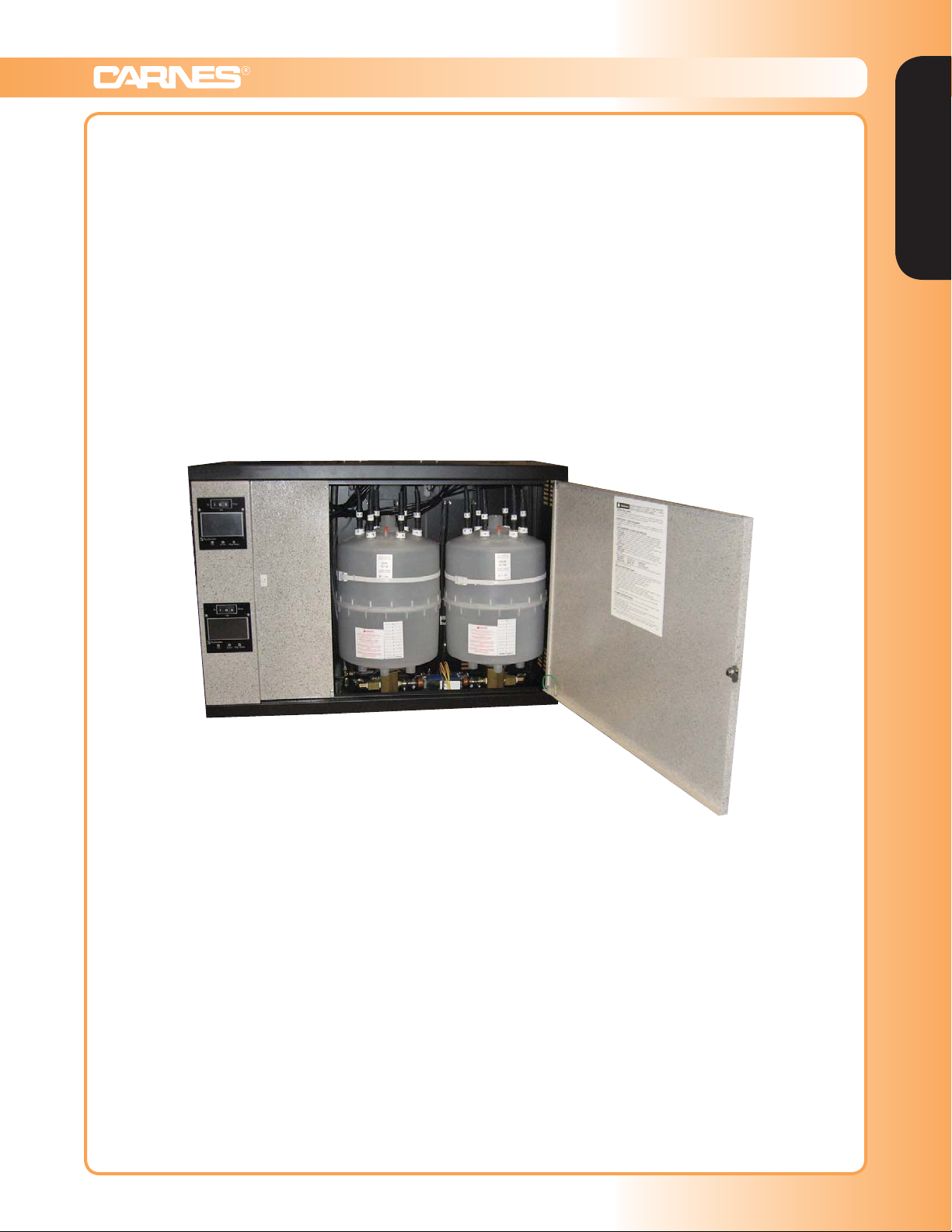
HCHH Shown
www.carnes.com G-1
Humidifiers | Steam Humidifiers
Humidifiers
CARNES MICROPROCESSOR CONTROLLED STEAM HUMIDIFIERS use ordinary
untreated tap water and convert it to mineral free steam for humidity control in commercial,
industrial, institutional and residential applications.
ECONOMICAL
Disposable Cylinders Eliminate Periodic Maintenance for Reduced Maintenance Costs
Fast and Easy Installation
Reliable Electronic Components for Long Life
EFFICIENT
Circuit Board Utilizes Microprocessor to Maximize Energy Conservation
Exclusive Circuit Board Design with Attached True Touchscreen Control Display
VERSATILE
Digital Output on a True Touchscreen Control Display Providing Status and Help Buttons For
Operational Details and Troubleshooting
Capacities up to 200 Pounds of Steam Per Hour Per Single Unit
Utilize any On-Off Humidistat, Carnes Proportional Humidistat or External Signal from DDC Controls
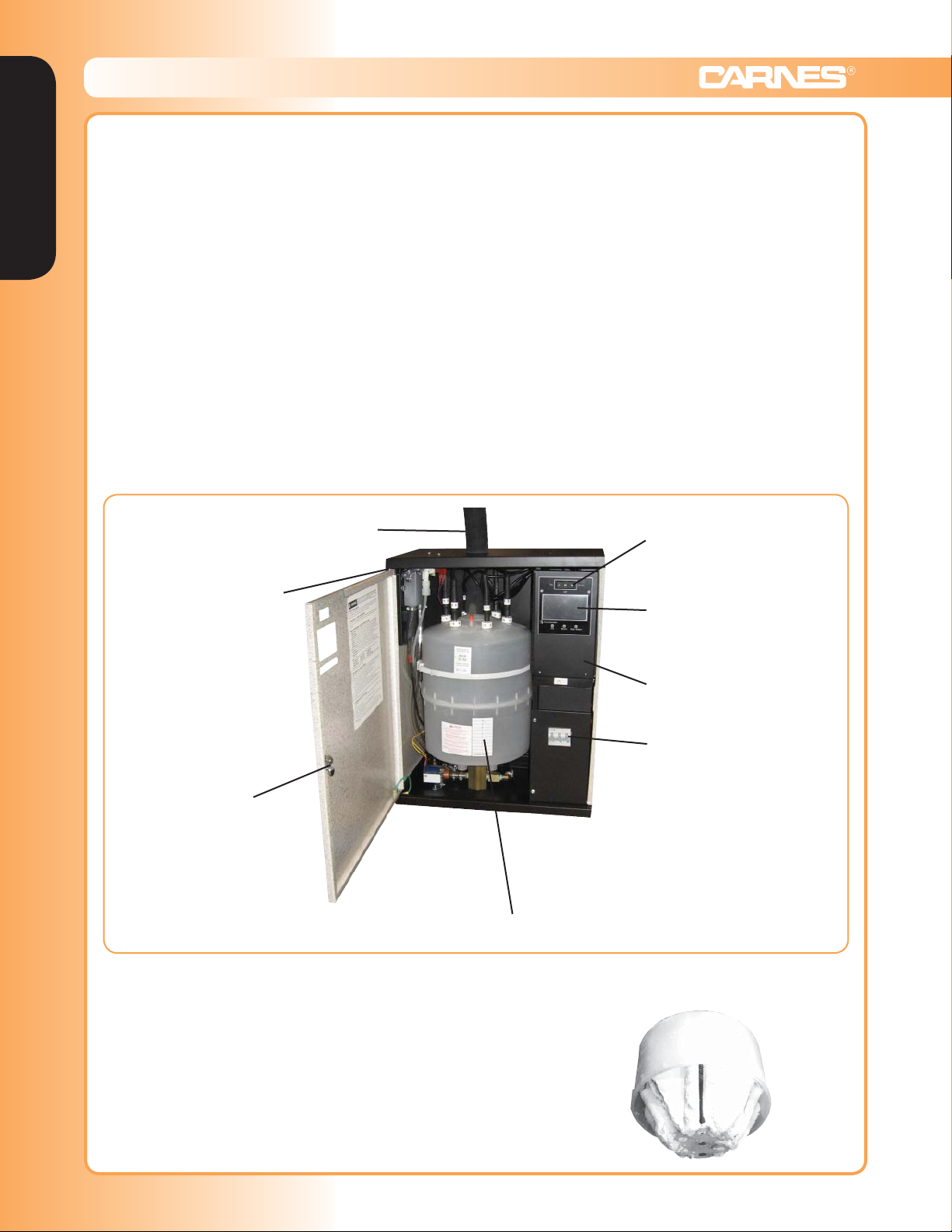
Flexible steam hose
distribution pipe.
Hinged and removable
door provides easy
access for service.
Door lock
prevents
unauthorized
adjustments.
connects to
HBGH Shown
Easy access
“On-Off-Drain”
Switch.
True Touchscreen
control display.
20 gauge metal partition
covers line voltage wiring
for added safety.
Optional internal circuit
breaker available. Please
note: certain units require
circuit breakers per NEC
48 amp guidelines.
Disposable plastic cylinder eliminates
periodic maintenance.
Cut-away used steam cylinder
The simplicity and unique advantages of humidity from
showing mineral deposits.
directly boiling water in disposable cylinders has been
well known since Carnes pioneered the concept in North
America in 1969. Pan type humidifiers require messy, time
consuming cleaning that may require the use of acids.
Electric heating elements in pan type units may also require
replacement. Easily changeable steam cylinders containing
electrodes can be replaced in less than five minutes.
G-2 www.carnes.com
Humidifiers | Displays & Internal Controls
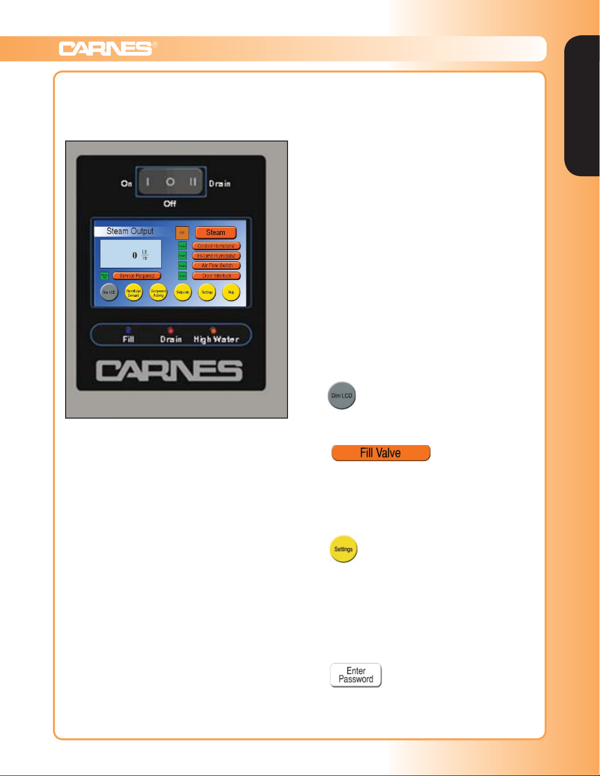
FRONT PANEL DISPLAYS & CONTROLS
The display on the front panel of the humidifier cabinet contains the “On-Off-Drain” switch, the LCD True
Touchscreen display and the “Fill”, “Drain” and “High
Water” LED’s.
“DRAIN” LED
The DRAIN LED is a red light illuminated when the
Drain Valve is activated. An activated Drain Valve
allows water to drain from the humidifier. An analogous
indicator, and a description of its operation, is offered in
the “Component Activity” menu.
“HIGH WATER” LED
The HIGH WATER LED is an orange light illuminated
when the High Water Sensor is activated. An activated
High Water Sensor indicates that the water has risen to
the maximum allowable level in the cylinder. This can
be a normal situation, particularly if the cylinder is being
filled with mostly unconditioned water. An activated High
Water Sensor can also be a sign that the cylinder is close
to end-of-life and needs replacing, or, in rarer cases, the
cylinder is not conductive enough for the fresh water
entering the humidifier. An analogous indicator, and a
description of its operation, is offered in the “Component
Activity” menu. More information on troubleshooting High
Water situations can also be found through the “Help”
menu on the home screen.
HUMIDIFIER TRUE TOUCHSCREEN MENU PAGES
The humidifier True Touchscreen user interface uses
color conventions to help the user navigate the controls.
The colors of different buttons indicate the following.
1. Gray —
Humidifiers
Figure P
“ON-OFF-DRAIN” SWITCH
In the “On” position the humidifier will operate if all controls are calling for humidity. The “Off” position is used
for seasonal shut down if desired. The “Drain” position
is used to drain water from the steam cylinder for maintenance. The fill solenoid valve will be on whenever the
drain is activated to reduce the drain water temperature.
LCD TRUE TOUCHSCREEN DISPLAY
This LCD True Touchscreen display offers the necessary interface to control and monitor many aspects of
the humidifier. On the home screen is the current steam
output in Lbs./Hr. (or Kg/Hr). To select either is available
in the settings menu. A “Service Required” indicator
and button outlining current service issues, indicators
for the four basic controls necessary for operation
(control humidistat, high limit humidistat, air flow switch and
door interlock), and various buttons which navigate to
other menu pages when pressed are also available
on the home page screen. The menu pages and their
capabilities are detailed further in “True Touchscreen
Menu Pages” section of this document.
“FILL” LED
The FILL LED is a blue light illuminated when the Fill
Valve is activated. An activated Fill Valve allows water
to flow into the cylinder of the humidifier. An analogous
indicator, and a description of its operation, is offered in
the “Component Activity” menu.
Dim LCD is the only gray button. More information is
available in the “home” page description.
2. Orange —
Orange buttons represent the object or subject
described across the button. Most orange buttons
have an indicator next to them, which can change
in color, e.g. green, yellow or gray. Pressing orange
buttons will bring you to a page which describes the
object or subject in question.
3. Yellow —
Yellow buttons navigate a user to a new page
dedicated to a set of functions. For example, the
“Humidistat Demand” button brings the user to a
page that shows what percentage demands both
the Control and High Limit Humidistats are currently
requesting, and details their functions. The bottom
of each page, other than the home screen, has
a square “Back” or “Home” button dedicated to
directing the user back to their previous page.
4. White —
White buttons are used for confirming or entering
data into the touchscreen. For example, they are
used to confirm a change to the “Max Output”
parameter, or entering a password to access the
“Settings” menu.
www.carnes.com G-3
Humidifiers | Displays & Internal Controls
Humidifiers
5. Maize —
Help buttons are used exclusively in the “Help”
page. These help buttons answer frequently asked
questions about the operation, maintenance
and troubleshooting of the humidifier. It is also a
convenient place to look at humidifier electrical data
when an IOM is not available.
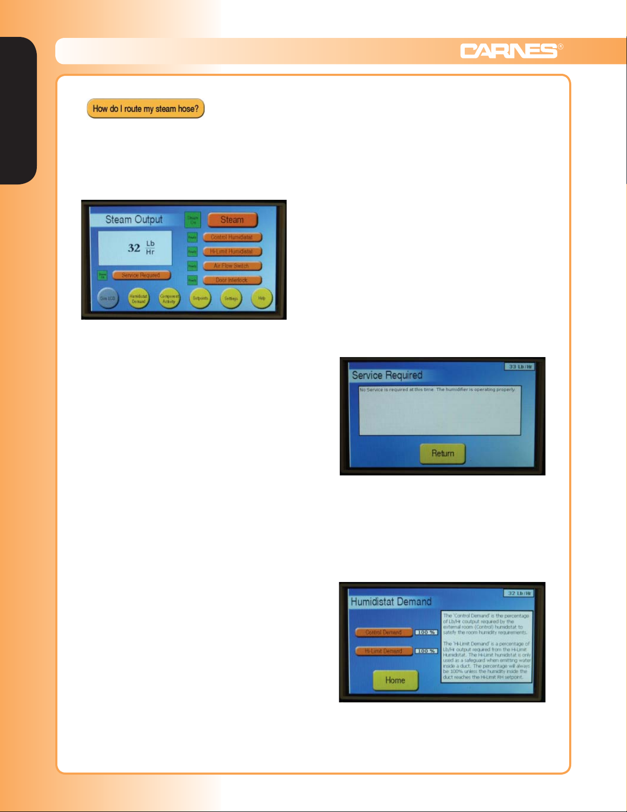
“HOME” PAGE
The home page is the main screen through which most
other pages can be accessed. The large blue square to
the left shows the steam output. The orange and yellow
buttons on the home page are considered “Operational
& Status” indicators. Touching any of these displays will
show dialog explaining the subject or status of that button.
The orange buttons also have indicator boxes to the left
showing actual status. Green shows ready to operate.
1. Dim LCD (gray) - As a power saving feature, press-
2. Humidistat Demand (yellow) - Brings the user to
3. Component Activity (yellow) - Button lists the
4. Setpoints (yellow) - The three setpoints of the unit
5. Settings (yellow) - Any settings of the humidifier,
6. Help (yellow) - Frequently asked questions about
7. Service Required (orange) - Invokes a page that
ing the Dim LCD button will shut the backlight of the
LCD off. Once off, pressing anywhere on the True
Touchscreen will turn the backlight on. The humidifier can also automatically turn off the backlight after
15 minutes. See the “Settings” page for more information on enabling/disabling the Auto-Dim feature.
a page that shows what percentage demands both
the Control and High Limit Humidistats are currently requesting, and further details their functions.
internal components used in the humidifier.
Their respective indicators showing whether the
components are activated or not. From this
page, the user can view more information on the
components and their functions.
are listed on this page. The setpoint is the target
Lb./Hr. output of the humidifier.
e.g. Max Output, Timers or Fan Speed, can be
accessed through this page. This page is password protected. For more information, refer to the
“Settings” page section.
the humidifier can be answered through the Help
page. It is a convenient resource to resolve many
issues quickly and effectively.
describes what service is needed by the humidifier,
if any. Indicator light to the left of the button turns
red when service is needed, and will otherwise
remain green. Refer to the separate “Service
Required” page for more information.
8. Steam (orange) - Explains the status of the “Steam”
indicator light. The humidifier will only produce
steam if the “Steam” indicator light is green. The
indicator will be brown when the On/Off/Drain
switch is in the “Off” position. It will turn yellow if
the switch is in the “On” position, but one or more
of the four basic controls are not satisfied (Control
Humidistat, High Limit, Air Flow, Door Interlock).
The light will turn green if all of the above switches
and controls are satisfied.
9. Control Humidistat (orange) - Explains the
status of the Control Humidistat indicator light,
and also shows the current demand of the Control
Humidistat.
10. High Limit Humidistat (orange) - Explains the
status of the High Limit Humidistat indicator light,
and also shows the current demand of the High
Limit Humidistat.
11. Air Flow (orange) - Explains the status of the Air
Flow switch.
12. Door Interlock (orange) - Explains the status of the
Door Interlock switch.
“SERVICE REQUIRED” PAGE
“SERVICE REQUIRED” PAGE
The “Service Required” page outlines any service issues
that are in need of being resolved. Many issues can be
traced back to variability in water parameters, and often
the solution can be dealt with through the changing of
cylinders or modifying timer values within the “Settings”
page. This page is used to alert the user and direct them
on the right path towards resolution.
“HUMIDISTAT DEMAND” PAGE
The Humidistat Demand page lists both the Control
Demand and the High Limit Demand of the humidifier.
Each demand signal is represented by an orange button,
and next to each button is a numerical box specifying
the percentage of demand each humidistat is currently
calling for.
G-4 www.carnes.com
Humidifiers | Displays & Internal Controls
The Control humidistat, which provides the Control
Demand, is normally the humidistat in the room being
humidified. It is either installed in the room itself or the
return air duct. The High-Limit humidistat, which provides
the Hi-Limit Demand, is a safe-guard humidistat installed
in the supply duct roughly 10-15 feet past the distribution
tube. This humidistat is usually set to a high level (8090%), and will shut down the humidifier if the humidity
gets too high in the supply duct. Without a High-Limit
humidistat properly installed, the supply duct could reach
a humidity level where any steam entering the duct would
readily condense.
Both Control humidistats and High-Limit humidistats
are wired in the same way, only Control humidistats
are wired to port J16 of the circuit board and High-Limit
humidistats are wired to port J17. Both ports have the
same number of pins and connection layout.
When using an on/off humidistat, the percentage
should be either 100% or below 20%. In this case the
control is either calling for full output or no output. On-Off
humidistats are dry-contact switches. They will have two
wires; each connected to pins 2 and 4 (in no particular
order/polarity).
For a proportional humidistat, any percentage value is
possible between 0% and 100%. In this case the humidifier can be modified to output any fraction of its max
output. If the proportional control falls to 20% or below,
the humidifier is shut off. The input signal of a proportional
humidistat must be of the 0-10V DC variety. Proportional
humidistats will have three wires, with ‘power’ going to
pin 1, ‘signal’ to pin 3, and ‘ground’ to pin 4.
In lieu of a humidistat, a DDC signal from a building
management system may also be used. Here, the ‘signal’
should be connected to pin 3, and ‘ground’ to pin 4. In
this case, ‘power’ can be ignored. A DDC signal must be
of a 0-10V DC variety, though a 4-20 mA control signal
can be converted to a 0-10V signal by adding a 470 Ohm
resistor between the ‘signal’ (pin 3) and ‘ground’ (pin 4).
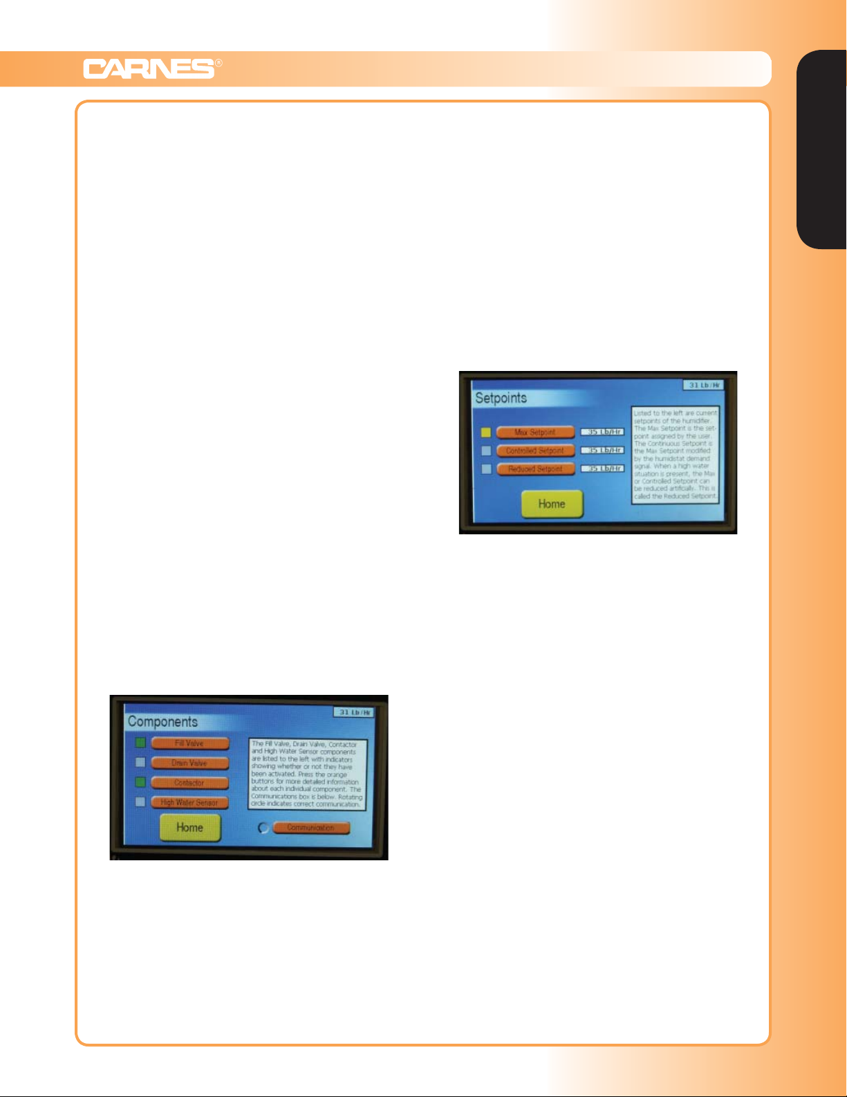
“COMPONENT ACTIVITY” PAGE
The Component Activity page lists all internal components that can switch on and off during operation. This
includes the Fill Valve, Drain Valve, Contactor, and High
Water Sensor. Each orange button in the component
list is accompanied by a colored indicator representing
whether or not the component is currently ‘on’. Green
indicates that the component is ‘on’, whereas gray
indicates the component is ‘off’. The Fill Valve is on
when the unit is either filling or draining the cylinder.
The Drain Valve is on when the humidifier is draining
the cylinder. The Contactor is on when the humidifier is
producing steam. The High Water Sensor is on when
the humidifier has identified a high water situation. When
in a high water situation, the fill valve is disabled for 5
minutes. At the end of 5 minutes the high water sensor
light will go out, the fill valve will open, if there is a call for
more humidity, and unit will continue normal operation.
High water sensors can be cumulative depending on the
condition of the water.
The other item present on this screen is the
Communication button. The Communication button has
a rotating indicator that represents whether the True
Touchscreen controller on the circuit board is properly
communicating with the microcontroller. If this icon is not
rotating and has a red ‘X’ through it, the information on
the screen is invalid and you should contact the factory.
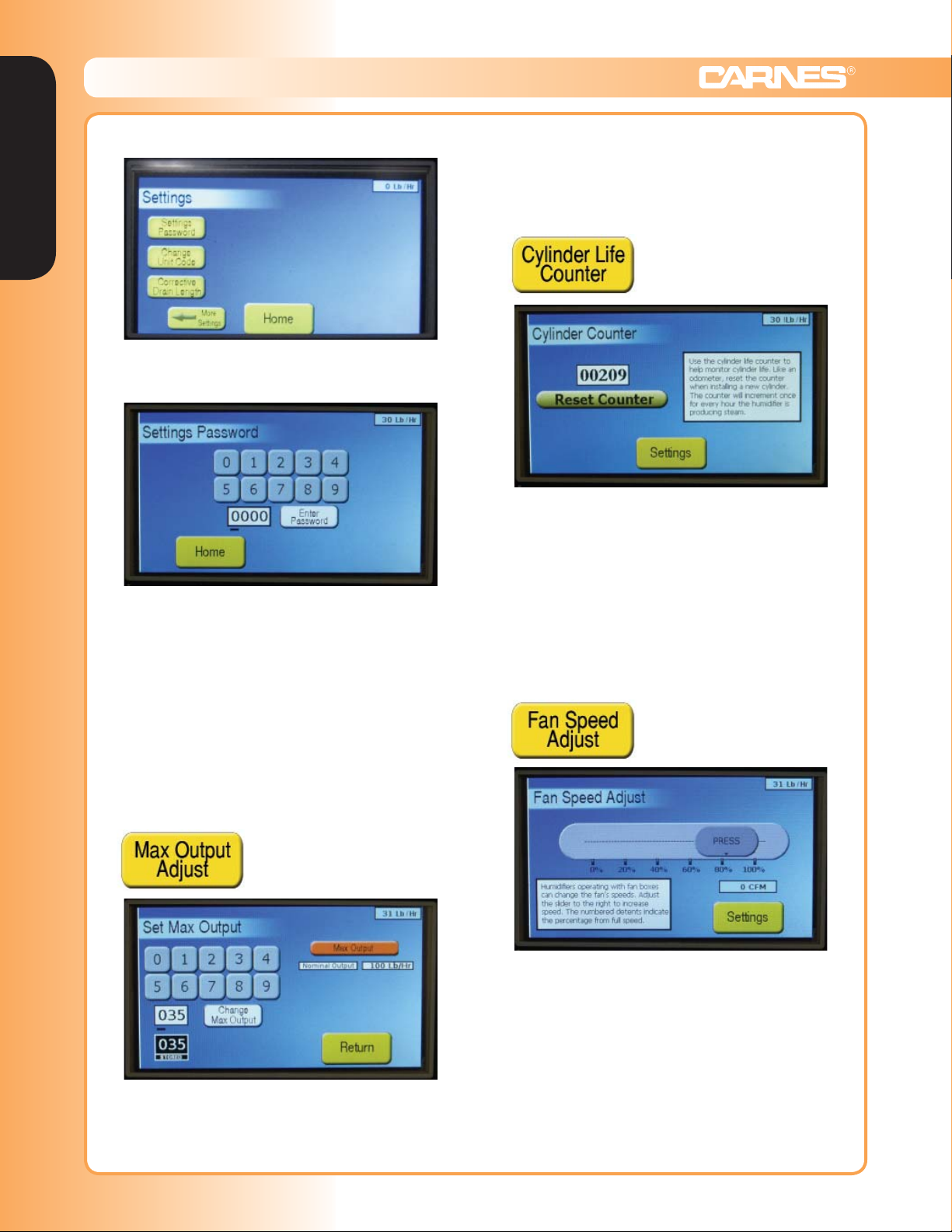
“SETPOINTS” PAGE
The Setpoints page displays the setpoints (the target
steam output of the humidifier) associated with the unit.
There are three different setpoints, but only one setpoint
is active at any given time. Each setpoint is accompanied
by the current value of the setpoint to the right, and an
indicator that represents its status. For all setpoints, the
following colors represent the status of the setpoints:
Gray – The setpoint is inactive because it is not
currently necessary.
Green – The setpoint is active, and the humidifier is
producing steam at or above the setpoint value.
Yellow – The setpoint is active, but the humidifier is
producing steam below the setpoint value.
Yellow/Black X – The setpoint is inactive because it is
being overridden by a setpoint with a higher priority.
The three different types of setpoint are as follows: The
Max Setpoint is the user-specified setpoint active when
no external controls or internal reduction is taking place.
The Max Setpoint is always modifiable via the “Max
Output Adjust” within the settings menu. The Controlled
Setpoint is the setpoint when a humidistat (Control or
High Limit), reduces the target output of the humidifier
due to changing room requirements. The Reduced
Setpoint is active when the unit requires a reduction in
output due to a high water situation.
The setpoints have the following priorities: The Reduced
Setpoint has the highest priority and always overrides the
Controlled Setpoint and the Max Setpoint when active.
The Controlled Setpoint has the next highest priority, and
always overrides the Max Setpoint. It should be noted
that the Reduced Setpoint is always lower than or equal
to the Max Setpoint (or Controlled Setpoint, if active),
and the Controlled Setpoint is always lower or equal to
the Max Setpoint.
Humidifiers
www.carnes.com G-5
Humidifiers | Displays & Internal Controls
Humidifiers
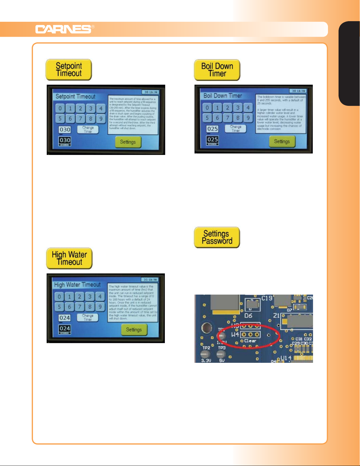
“SETTINGS”
The Settings menu is the page where all operational
values can be set. It is password protected by default,
with a default password of ‘1212’.
The password can be disabled under the ‘Settings
Password’ on the second Settings page. See ‘Settings
Password’ section for more details.
of the humidifier. The Maximum Output value, when
changed, also changes the Max Setpoint value on the
Setpoints page.
Cylinder Life Counter –
This page consists of a counter where the user can
monitor the life, in hours, of the cylinder. When changing
a cylinder, press the ‘Reset’ button on this page to reset
the timer. The Cylinder Life Counter only counts the
amount of actual runtime of the cylinder (the time when
the contactor is pulled in). The counter value is saved
even when the humidifier is powered down. The national
average cylinder life is about 1150 hours, but this can
vary greatly depending on individual water conditions.
Any adjustment made to any setting can be done ‘on-thefly’. Which means when a change occurs, the humidifier
will react accordingly without the need of shutting off the
unit or even stopping steam output. In general, any page
within the True Touchscreen system can be accessed,
monitored, or changed ‘on-the-fly’.
Max Output Adjust –
This page adjusts the Maximum Output of the humidifier.
The Maximum Output can be adjusted lower from the
nominal output value of the unit (set at the factory). The
unit cannot be set lower than 20% of the nominal value
Fan Speed Adjust –
This page consists of a slider bar that can change the
speed of the fans when the humidifier is connected to
an optional blower box. This slider bar will not affect the
operation of the humidifier if no blower box is attached.
The bar can change the speeds of the fans from 0 to
100% of the max fan speed. Also displayed on this page
is an estimate of the current fan air output, in Cubic Feet
per Minute (CFM). This adjustment is particularly useful
if the humidifier is of a smaller capacity, and less noise
from the fans is appreciated.
G-6 www.carnes.com
Humidifiers | Displays & Internal Controls
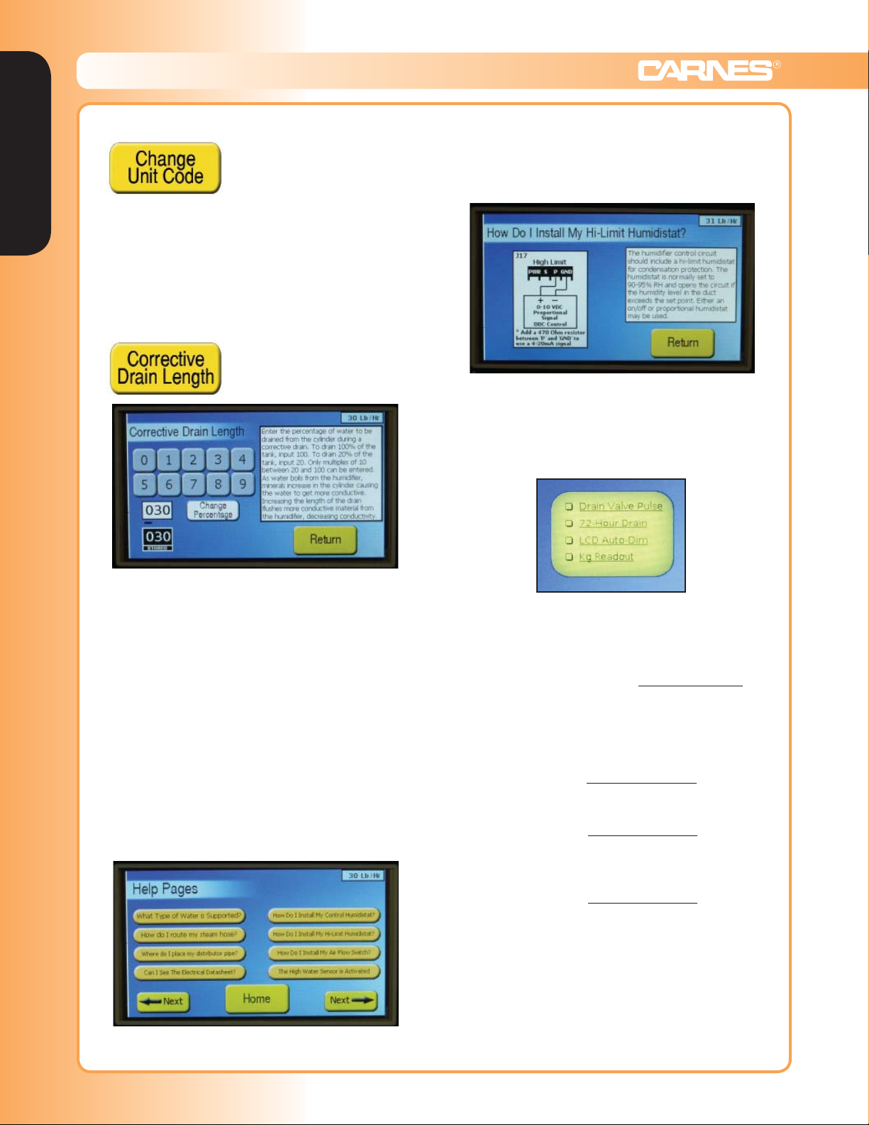
Setpoint Timeout –
This page is where the Setpoint Timeout value is set. The
maximum amount of time allowed for the unit to reach
setpoint during a fill sequence is designated by the
Setpoint Timeout. Its default value is 30 minutes, but
can be set as high as 255 minutes. After the timer
expires during a fill sequence, the humidifier assumes
the drain valve is stuck open (due to sediment buildup),
and begins pulsing the drain valve to attempt to unclog
it. After the pulsing routine, the humidifier will attempt to
reach setpoint for a second and third time. After the third
attempt without reaching setpoint, the unit will shut down.
Boil Down Timer –
Humidifiers
This page is where the Boil Down Timer is set. The Boil
Down Timer is variable between 0 and 255 seconds,
with a default value of 25 seconds. Setting the Boil Down
Timer higher will result in an increased water level, and
less-conditioned water. This may be helpful in reducing
low water level induced arcing and corrosion of cylinders.
More water is consumed by the humidifier when the Boil
Down Timer value is increased.
Settings Password –
High Water Timeout –
This page is where the High Water Timeout value is
set. This is the maximum amount of time allowed for
the unit to run in a ‘Reduced Setpoint’ mode (See
Setpoints page). The timeout has a range from 0 to 168
hours, with the default being 24 hours. If the humidifier
setpoint is artificially reduced due to a high water situation, the humidifier will continue to run. If the humidifier
cannot work it’s way back up the normal max/controlled
setpoint, the humidifier will shut down after the High
Water Timeout value elapses.
This page is where the password for the settings menu
can be changed or disabled.
If the password for the Settings menu is forgotten, it can
be reset. To do this, remove power to the humidifier,
move the jumper on W4 from pins ‘1 and 2’ to ‘2 and 3’,
and power the unit back on.
Return the jumper to pins ‘1 and 2’ afterward. Pins ‘1 and
2’ are to the left, and pins ‘2 and 3’ are to the right.
The different yellow buttons on both setting pages allow
for the changing of different values. Below is a brief
summary of each, and more information can be accessed
within the page itself.
www.carnes.com G-7
Humidifiers | Displays & Internal Controls
Humidifiers
Calibration Password –
This page is where the Humidifier Unit Code, the four
digit number identifying the humidifier, is programmed
into the unit. This page is password protected, and
number should not be modified by the end user. Contact
the factory if further information is needed.
Corrective Drain Length –
The help pages consist of maize color buttons labeled
with questions. When a button is pressed, information
will be given answering and/or giving information about
the subject in question. A basic help page consists of text
and/or diagrams to help the user through basic problems.
For example, in the picture above the question of how to
install a high limit humidistat is answered with a diagram
and corresponding text. Some pages consist of more
buttons to help guide a user through different processes.
These buttons can be used and referenced as needed.
Checkboxes –
This page is where the Corrective Drain Length is set.
This value represents how much water should be drained
from the cylinder when the humidifier senses a corrective drain is needed. As water boils from the humidifier,
minerals increase in the cylinder causing the water to
get more conductive. Increasing the length of the drain
flushes more conductive material from the humidifier,
decreasing the water conductivity.
The input here is a percentage value. To set the
Corrective Drain Length to drain 20% of the cylinder
during a corrective drain, input 020. To drain all of the
tank, input 100. 30 is the default value, and only multiples
of 10 between 20 and 100 can be entered.
“HELP”
There are a few operational options that do not need
separate pages, and therefore are only enabled/disabled via checkboxes on the main Settings Page. Their
functionality is described as follows:
The Drain Valve Pulse option is enabled by default. This
option allows the drain valve to pulse when the humidifier executes a corrective drain. This actuates the water
within the drain piping, allowing for minerals buildup to
be discharged more easily. Enabling this option will make
the unit noisier whenever a corrective drain is executed.
The 72-Hour Drain is disabled by default. This option,
when enabled, allows the humidifier to drain the cylinder
completely after 72 hours of idle operation.
The LCD Auto-Dim is disabled by default. This option,
when enabled, will automatically turn off the backlight of
the LCD after 15 minutes of idleness. This feature can
save on energy consumed.
The Kg./Hr Readout is disabled by default. This option,
when enabled, will turn the steam readout on home page,
and in the upper right hand corner of other pages, into
Kg/Hr instead of Lb/Hr.
G-8 www.carnes.com
Humidifiers | Steam Humidifiers
APPLICATIONS
COMFORT
Temperature and relative humidity affect the comfort and
well being of all living things. High temperatures require
low humidity to maintain comfort conditions, while low
temperatures can more easily be tolerated at high
relative humidity. Humidification occurs when air is
moisturized by a humidification unit or when hygroscopic
materials (materials containing moisture) lose moisture
to drier air. Proper humidification is widely accepted as
healthy, minimizing employee illness and lost work time.
MATERIALS STORAGE
Paper, fabrics, wood, plastic, chemicals and most other
materials are hygroscopic. Their water content depends
on the humidity of the air around them. If air is too dry,
these substances lose moisture until an equilibrium is
reached between hygroscopic materials and the air.
PROCESS
Process operations, such as data processing areas, are
affected by two major humidity factors: hygroscopic
material and generation of static electricity.
Hygroscopic material used in the process influences
material weights, dimensions and workability.
Static Electricity can totally disrupt high speed process
operations as found in a data processing center, paper or
film handling business. Created by friction between two
substances, static electricity can be prevented by proper
humidification of the process environment.
RECOMMENDED TEMPERATURE AND HUMIDITY
RANGE - Table 1
APPLICATION TEMP F° RH %
Computer Rooms 72+2 50+5
Office Buildings 70-74 20-30
Libraries & Museums 68-72 40-55
Archival Libraries & Museums 55-65 35
Art Storage 60-72 50+2
Stuffed Animals 40-50 50
Bowling Centers 70-74 20-30
Health Facilities
Full Term Nursery 75 30min.-60max.
Special Care Nursery 75-80 30min.-60max.
Patient Rooms 75 30
Intensive Care 75-80 30min.-60max.
Operating Rooms 68-76 50min.-60max.
Recovery Rooms 75 50min.-60max.
Lasik Eye Centers
Electrical Instrument Mfg. 70 50-55
Fur Storage 40-50 55-65
Photo Film Darkroom 70-72 45-55
Photo Print Darkroom 70-72 45-55
Photo Drying Room 90-100 35-45
Photo Finishing Room 72-75 40-55
Cellophane Wrapping 75-80 45-65
Animal Laboratories
Mouse, Rat 64-79 40-70
Cat 65-85 30-70
Dog 65-85 30-70
Primate 65-84 30-70
Clean Rooms 67-77 40-55
Printing Plants
Lithography 76-80 43-47+2
Rotogravure 45-50+2
Collotype 80+2 85+2
Platemaking 75-80+2 45+2
Telephone Terminal Rooms 72-78 30-40
Radio and TV Studios 74-78 30-40
Reprinted with permission of the American Society of Heating, Refrigerating
and Air Conditioning Engineers, Inc., Atlanta, GA 30329.
+ = plus or minus
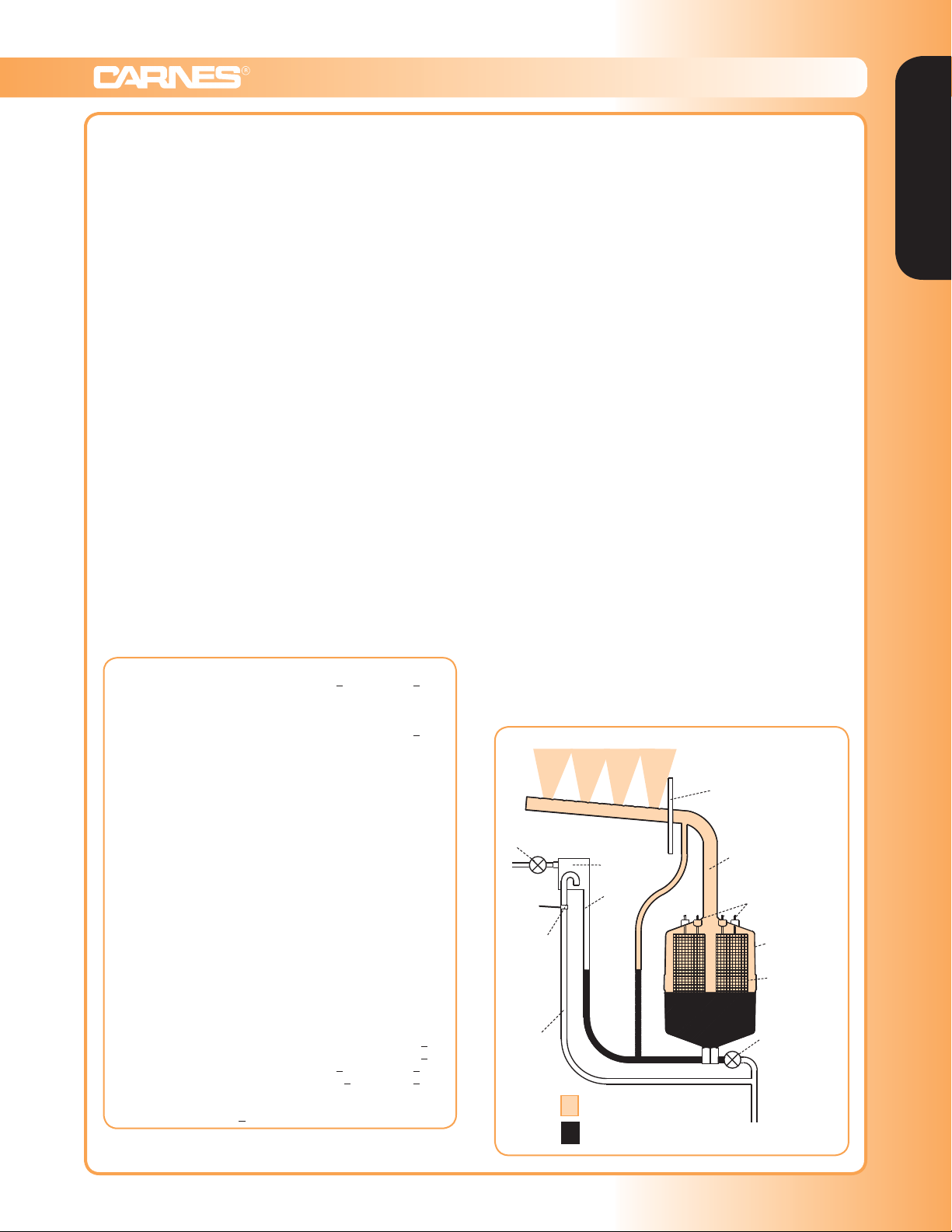
OPERATION
Upon a signal from external controls the circuit board
opens a fill solenoid valve, allowing water to flow across
an air gap into a standpipe. The standpipe provides a
column of water to be fed into the cylinder using gravity.
The air gap prevents back flow into the water supply
and prevents the cylinder from becoming a pressure
vessel. The steam cylinder operates at a pressure of
approximately 1/2 psi.
The circuit board also closes a power contactor allowing
current to flow to vertical electrodes sealed inside the
cylinder. Current flows between the electrodes using
minerals in the water as a conductor. The water is
heated to boiling and converted to steam which leaves
the cylinder through the flexible steam hose which is
connected to the steam distributor pipe.
The circuit board reacts to current flow between the
electrodes and automatically opens the fill solenoid valve
when more water is required to maintain the desired
output rate, and closes when the desired rate is
reached. The operation of the drain solenoid valve
is automatically controlled by the circuit board which
responds to any changes in water conditions and drains
the required quantity of water to provide stable operation
and long cylinder life.
As mineral deposits build up within the cylinder the water
level will slowly rise to contact clean electrode surfaces
to maintain the desired steam output rate. When mineral
deposits have covered all available electrode surface
areas, current flow will be reduced to a level where the
desired steam output cannot be reached and the service
light will signal the need for maintenance. When the
cylinder is filled with minerals it is easily changed in less
than five minutes.
Figure A
Steam
Distributor
Pipe
Fill
Solenoid Valve
Air Gap
Stand
Pipe
Non Contact
High Water
Sensor
Overflow
Tube
STEAM
WATER
Steam
Hose
From Power
Contactor
Cylinder
Vertical
Electrodes
Drain
Solenoid
Valve
To Drain
Humidifiers
www.carnes.com G-9
 Loading...