

Page 1
READ AND SAVE THESE INSTRUCTIONS
MODEL HRAA TECHNICAL MANUAL
INSTALLATION, OPERATION AND MAINTENANCE INSTRUCTIONS
CARNES COMPANY, 448 S. Main St., P. O. Box 930040, Verona, WI 53593-0040 - Phone: 608/845-6411 - Fax: 608/845-6470 [email protected] www.carnes.com
FORM 16799
ISSUED: 06-08
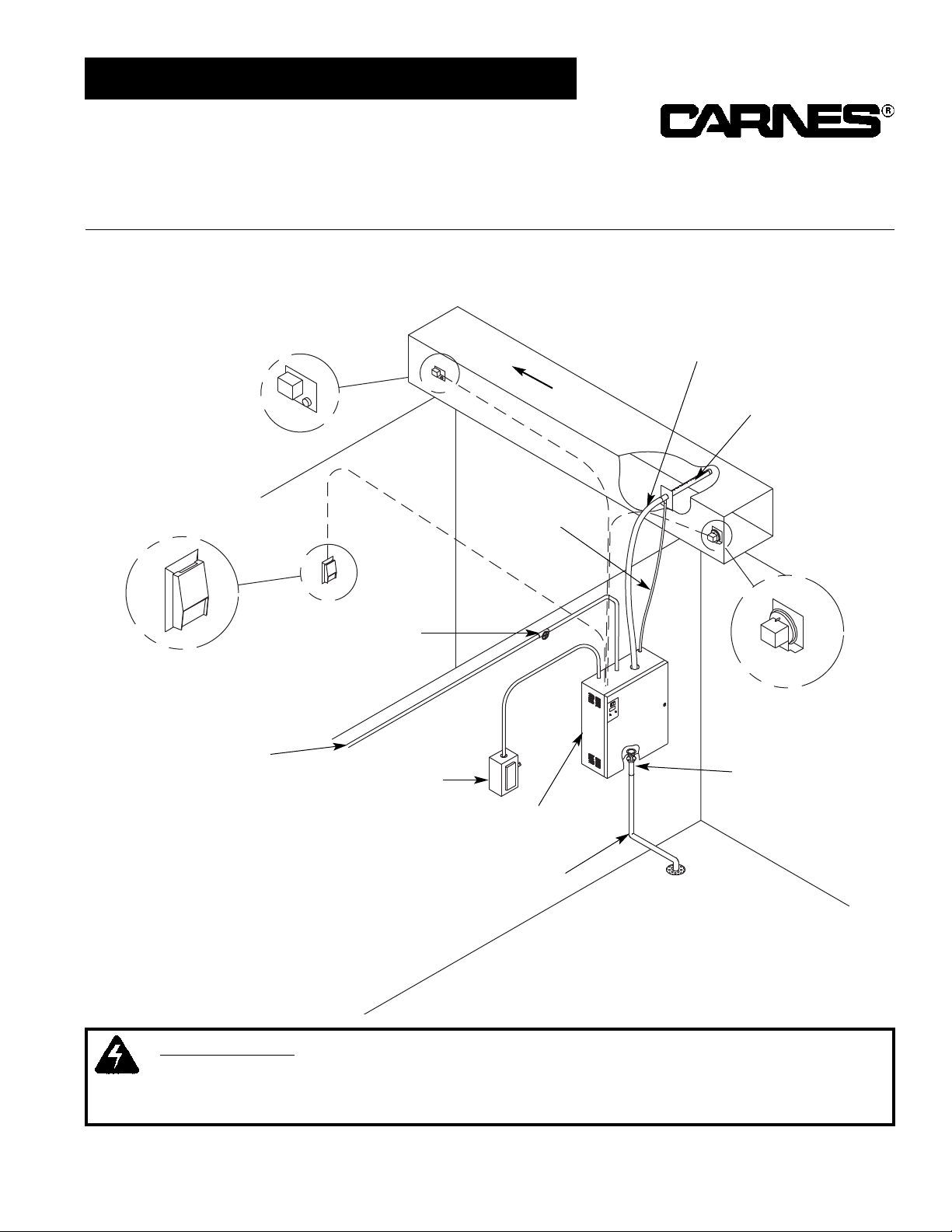
TYPICAL INSTALLATION
Figure A
High Limit
Humidistat
Steam
Hose
Steam Distributor
Pipe
Condensate
Return Line
Water Shutoff
Valve (By Others)
Wall Humidistat
Cold Water Line
Fused Disconnect
or Circuit Breaker
(By Others)
Air Flow Switch
Air Flow
Humidifier
Cabinet
Drain Line
Air Gap
Drain Fitting
WARNING:
THE HUMIDIFIER CABINET CONTAINS HIGH VOLTAGE WIRING AND HOT
SURFACES. THE CABINET DOOR INCLUDES A LOCK AND ACCESS MUST BE LIMITED TO
TRAINED AND QUALIFIED PERSONNEL ONLY. THE DOOR MUST BE LOCKED AND KEY MUST
BE KEPT IN A SECURE LOCATION AWAY FROM THE HUMIDIFIER
Page 2
2
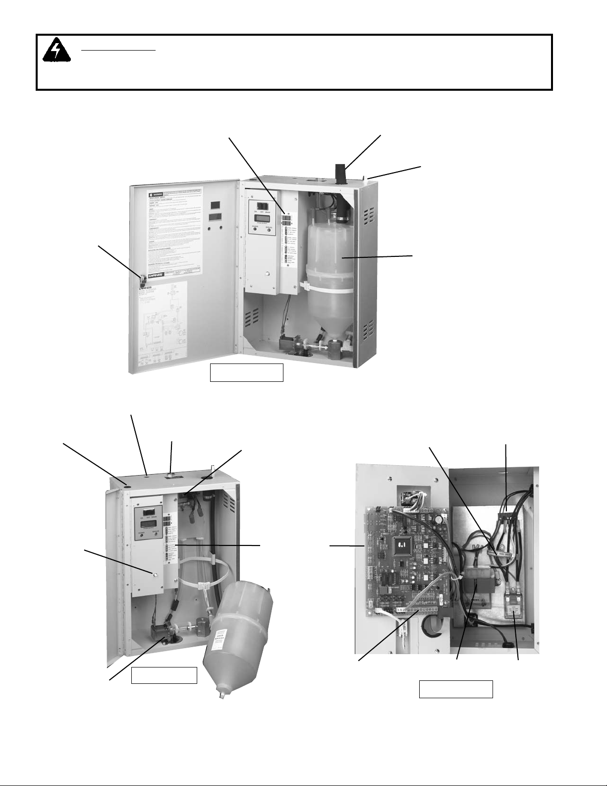
Steam
Cylinder
Hinged Door
with Key Lock
Steam Hose
Diagnostic
Display Panel
Condensate
Return Inlet
Figure B
Hole For
Power Wiring
Hole for
Control Wiring
Water Inlet
Fill Solenoid
Valve
Door
Interlock
Switch
Drain Solenoid
Valve
Figure C
Wiring Access
Panel
Electric Power
Terminals
Current
Sensing
Transformer
Control Connection
Terminals
Power
Contactor
(Relay)
Power Transformer
Figure D
WARNING:
INSTALLING AND SERVICING THIS EQUIPMENT CAN BE HAZARDOUS DUE TO
ELECTRICAL COMPONENTS AND HOT SURFACES. ONLY TRAINED AND QUALIFIED PERSONNEL
SHOULD INSTALL, REPAIR OR SERVICE THIS EQUIPMENT. INSTALLATION MUST BE MADE IN
ACCORDANCE WITH ALL APPLICABLE CODES AND STANDARDS.
Page 3
INSTALLATION
UNPACKING AND INSPECTION
1. An envelope shipped with the cabinet contains the
cabinet keys and Installation, Operation and
Maintenance Instructions.
2. The following optional components are packed in a
separate shipping carton for connection when
installing the humidifier.
A. Steam Distributor Pipe.
B. Steam Hose.
C. Condensate Return Line.
D. Humidistats and Air Flow Switches.
E. Steam Hose Clamps.
F. Condensate Return Clamps.
G. Air Gap Drain Fitting.
The distributor pipe should be located to insure best
distribution of steam into the airstream. A minimum
clearance of 4” must be maintained between the top of
the duct and the distributor pipe.
The steam distributor pipe is usually located in the supply
duct downstream of the fan. It is important to locate the
distributor as far upstream as possible from any obstructions in the ductwork so that air can absorb the steam
before it impinges on a surface and condenses. There
must be minimum of three feet between the distributor
and any fans, coils, filters, dampers, elbows or outlets
downstream to reduce the possibility of condensation.
Duct air temperatures below 60°F may require a condensate drain pan, supplied by others, below the steam
distributor pipe.
STEAM DISTRIBUTOR PIPE LOCATION
In a typical installation the humidifier is located below a
duct as shown in Figure A. The distance between the
humidifier cabinet and the steam distributor pipe should
be the shortest possible.
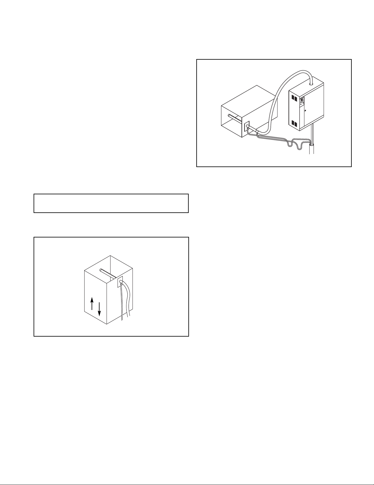
In a vertical duct with either upward or downward air flow
the distributor pipe should be installed horizontally.
The maximum length of steam hose that may be
installed is 10 feet.
Figure E
AIR
FLOW
The distributor pipe may be located below the humidifier
if the installation is made as shown in Figure F. A trap
may be necessary to prevent steam from flowing back
through the condensate return line.
Figure F
INSTALL STEAM DISTRIBUTOR PIPE
The steam distributor pipe must be mounted on a plumb
surface so that it is inclined upward. This is required so
the condensate, which forms in the distributor pipe, will
drain into the return line.
Insert the distributor pipe into duct and secure with four
sheet metal screws, not provided.
3
Page 4
DRAIN LINE CONNECTION
1. Remove the large nut and plastic gasket located on
the fitting on the bottom of the cabinet. The nut and
gasket may be used with standard type drain fitting if
an air gap fitting is not required by local codes.
2. Connect the air gap drain fitting to the cabinet drain
connection. It may be necessary to cut off some of the
air gap fitting depending on available space.
3. Connect the drain or air gap fitting to S or P trap or run
piping to a floor drain. Use plumbing material capable
of handling hot water, such as copper or CPVC.
CONNECT THE STEAM HOSE & CONDENSATE
RETURN LINE
COPPER TUBE IS THE ONLY ACCEPTABLE SUBSTITUTE FOR STEAM HOSE OR CONDENSATE RETURN
LINE.
1. The steam hose should be installed so there is a
continuous rise from the humidifier to the distributor
pipe. The rise should be 2” in 12” to allow proper
condensate drainage.
Support the steam hose at intermediate points to prevent
dips or pockets. It is very important that both the steam
hose and condensate return line be installed so that sags
are prevented. The steam is at very low pressure and it
cannot overcome resistance caused by water standing in
the steam hose. Water accumulating in sags in the return
line will restrict the flow and may cause water to enter the
duct from the distributor pipe.
If it is difficult to install the steam hose to prevent sags, it
is recommended that copper tube be used as a substitute. Size 3/4” copper tube can be used. Any 90° elbows
are approximately equivalent to three feet of steam hose.
If copper tube is used, a minimum of one inch of
insulation must be applied to prevent excessive
condensation and contact with the hot pipe. A short
length of steam hose must be used to connect the
cylinder in the humidifier to the copper tube. Another
short length should be used to connect the copper tube
to the distributor pipe. Any turns in the hose should have
a minimum radius of 8” to prevent kinking.
2. Fasten the steam hose to the distributor pipe with one
of the hose clamps provided.
3. Push the steam hose through the opening on the top
of the humidifier cabinet and slip over the outlet stub
on the top of the cylinder. Fasten with the hose clamp
provided.
4. Fasten the condensate return line to the distributor pipe with
the hose clamp provided. Connect the return line to the
condensate return inlet with the hose clamp provided.
If it is impossible to maintain a drop to the top of the
cabinet, it will be necessary to run the condensate return
line directly to the air gap drain fitting or some other drain.
A trap (usually 8” is sufficient) may be necessary to prevent loss of steam through the return line. Do not install
a trap if condensate is returned to the top of the cabinet.
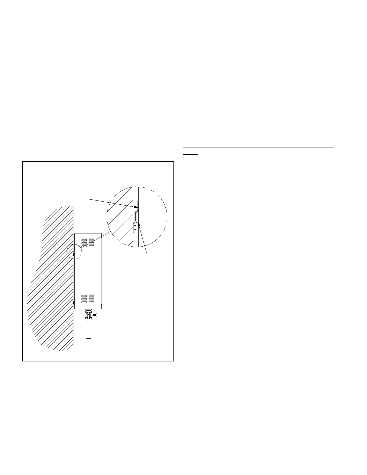
MOUNTING THE HUMIDIFIER
Locate the humidifier cabinet level and plumb on a
surface as close to the steam distributor as possible at a
convenient height for servicing. Allow 1” or more on the
sides for ventilation and 16” from the bottom to the floor
to allow for drain connections. Allow at least 16” in front
of cabinet for door opening. Consult local and national
codes prior to installation and comply with any provisions
they require.
The humidifier must never be located outside or where it
may be exposed to freezing temperatures unless a
heated, ventilated, weatherproof enclosure by others is
provided. Do not mount humidifiers on a hot or vibrating
surface.
Maximum operating weight is 70 pounds. Fasten the
mounting bracket to wood studs or solid wood.
Recommended fasteners: Four 1/4” x 1” long lag screws.
Fasteners are not provided.
Place the mounting flange on the humidifier cabinet over
the mounting bracket. A sheet metal screw should be
installed through the back of the humidifier cabinet to
secure the humidifier to the mounting bracket.
WATER SUPPLY CONNECTION
DO NOT
use hot water, deionized water, or water
that has been treated by a water softener without
consulting the factory.
Use ordinary tap water (20 to 120 psi). A 1/4” FPT fitting
is provided at the top of the humidifier. A shutoff valve,
not provided, must be installed ahead of this fitting.
MOUNTING FLANGE
MOUNTING BRACKET
AIR GAP
DRAIN FITTING
Figure G
4
Page 5
5
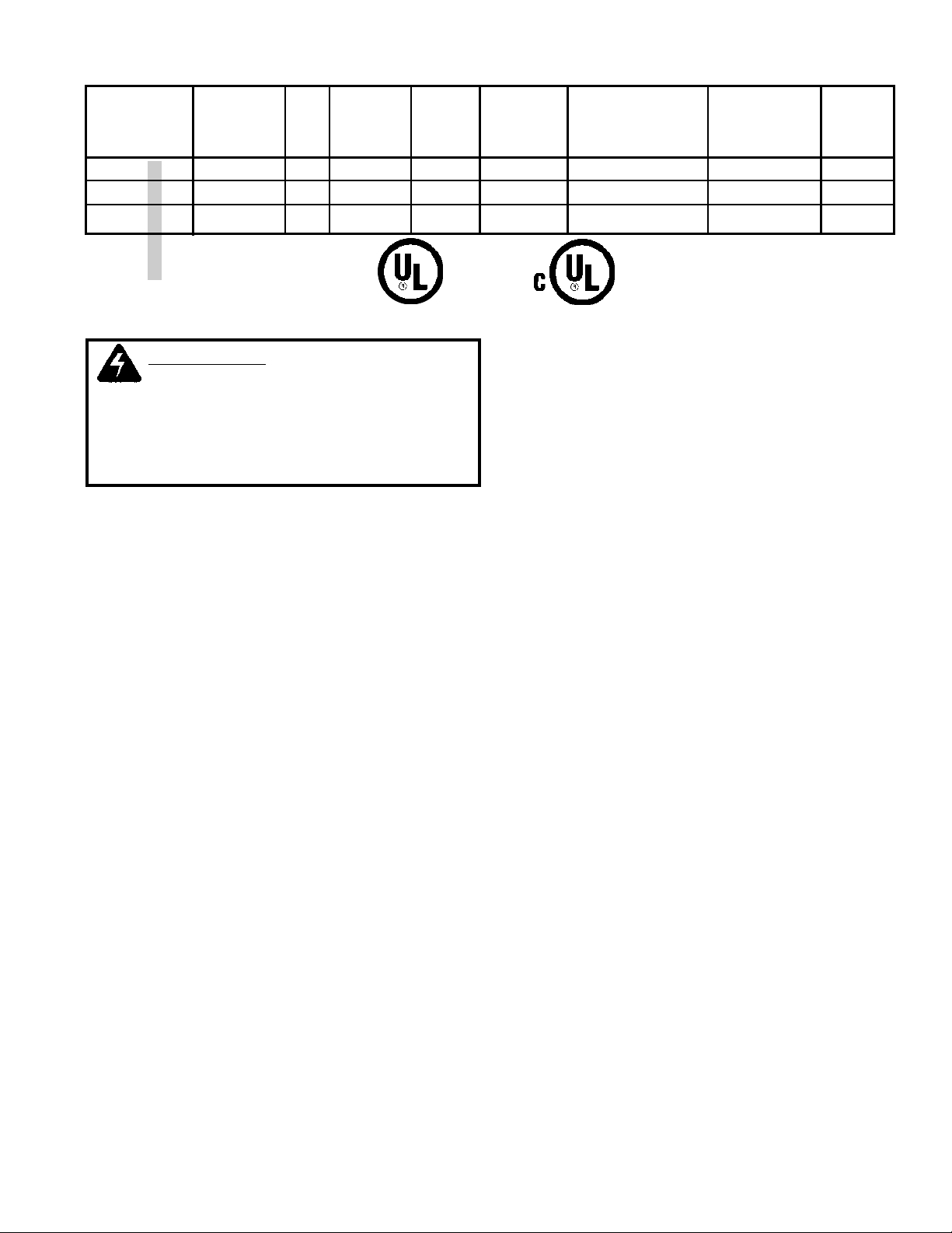
Line Recommended Digital
Maximum Amp Disconnect Steam Display
Model Lb./Hr. kW Voltage Phase Rating Size (Amps) Cylinder Code
HRAAA U 005 5 1.7 120 1 14.4 20 HXCBAX220 0005
HRAAD U 005 5 1.7 230 1 7.5 15 HXCBAX380 3005
HRAAD U 010 10 3.4 230 1 15.0 20 HXCBAX380 3010
U = UL
C = cUL
ELECTRICAL DATA
Check unit electrical characteristics on label outside of
cabinet. They must agree with power provided to the unit.
A fused disconnect or circuit breaker, not provided, must
be installed per local and national codes.
1. Remove screws securing hinged panel for access to
wiring.
2. An opening is provided on the top of the electrical
section. Bring electrical power lines through this
opening and connect to the electric power terminals
as shown on wiring diagram.
3. Replace electrical cover panel.
CONTROLS
CONTROL HUMIDISTAT
Either a wall-mounted humidistat or duct-mounted
humidistat in the return air may be used. The wall-mounted humidistat is the most common as it allows the setting
to be easily adjusted to accommodate changing requirements or to lower the level of relative humidity in the
space to prevent condensation on windows during
extremely cold weather. Room humidity is usually set in
range of 30-40% RH. Other settings may be necessary
for certain conditions.
If an on-off humidistat is used the humidifier will generate
steam at the preset output rate and cycle on or off as
necessary to satisfy the conditioned area requirements.
If a proportional humidistat is used the humidifier will
automatically vary the steam output rate in the range of
25-100% of the humidifiers maximum rating in response
to the humidistat. Proportional control provides less on-off
cycling of the humidifier.
ELECTRICAL CONNECTIONS
WARNING:
BEFORE MAKING ANY
ELECTRICAL CONNECTIONS SWITCH
POWER OFF AT SERVICE PANEL, FUSED
DISCONNECT OR CIRCUIT BREAKER AND
LOCK THE DISCONNECTING MEANS TO
PREVENT POWER FROM BEING
SWITCHED ON ACCIDENTALLY.
AIR FLOW DETECTION
The humidifier control circuit should include some method
to confirm air flow. If the steam distributor pipe were
“located in a duct where there is no air flow and the
control humidistat is calling for humidity, steam would be
discharged into the duct where it would immediately
condense.
Air flow may be detected by using a pressure differential
switch that detects air flow by sensing static pressure in
the duct.
CONDENSATION PROTECTION
An additional device may be used to provide condensation protection in the duct system. A high limit humidistat
may be installed 10 feet downstream from the steam
distributor pipe. This humidistat is normally set to 90-95%
RH and opens the circuit if the humidity level in the duct
exceeds the set-point. Once the humidity level returns
below the set-point, humidifier operation will resume
following a delay of several minutes after reclosure of the
circuit. Use of this device is recommended particularly
when the humidifier is used in applications where cooling
air is being humidified.
Either an on-off or proportional high limit humidistat may
be used. If a proportional humidistat is used the output of
the humidifier will automatically be decreased to reduce
the possibility of condensation. Two proportional humidistats may be used. One may be located in the area to be
humidified or its return duct and another as a high limit in
the supply duct. The humidifier will automatically select
the lowest signal to control the humidifier output.
EXTERNAL MONITORING
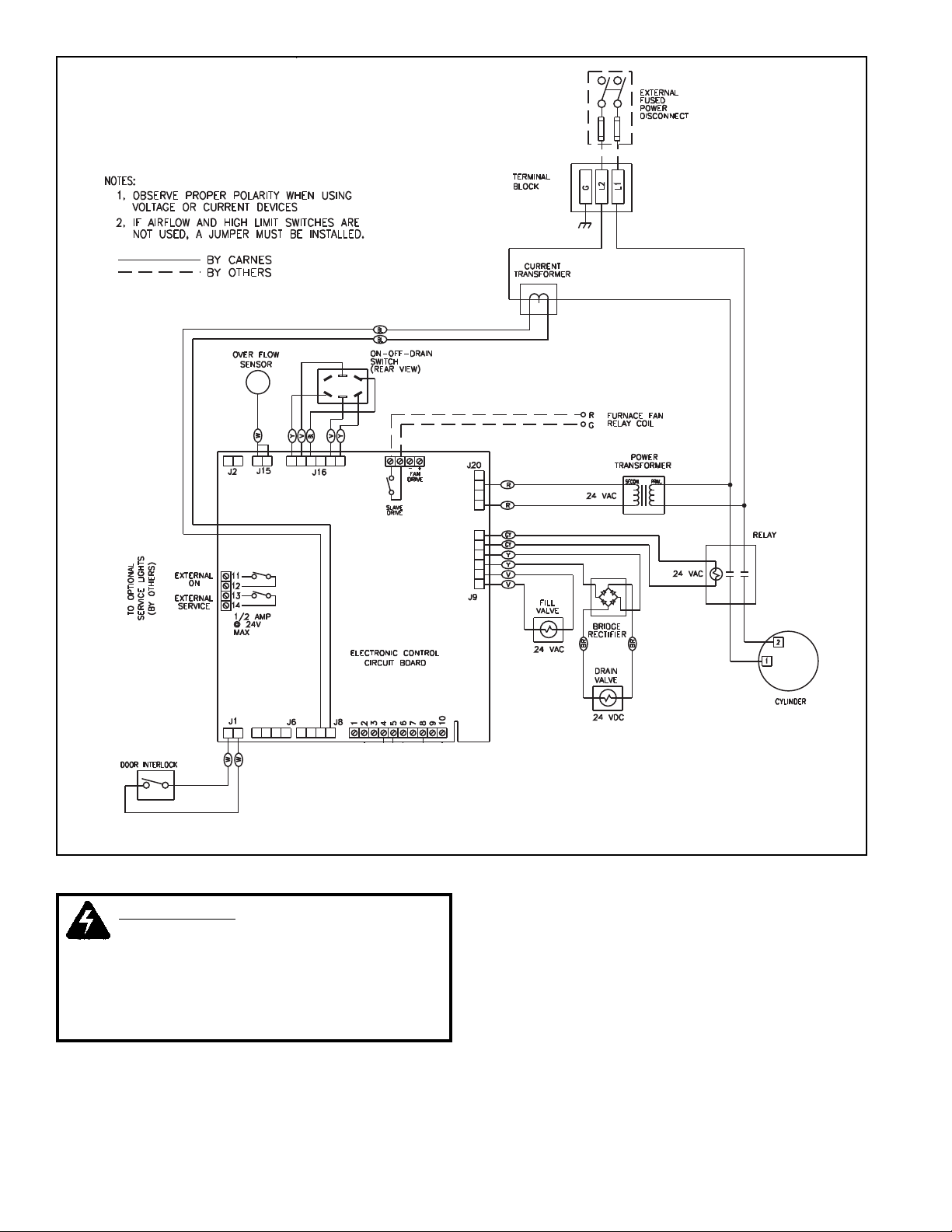
Terminals 11 and 12, shown in Figure H are provided for
remote monitoring of the status of the humidifier if
desired. When the unit is on terminals 11 and 12 are
closed. When the output of the humidifier is less than
50% of set-point terminals 13 and 14 are closed indicating a need for service. Each set of terminals is capable of
switching 1/2 amp at 24 volt maximum.
Page 6
WARNING:
BEFORE MAKING ANY
ELECTRICAL CONNECTIONS SWITCH
POWER OFF AT SERVICE PANEL, FUSED
DISCONNECT OR CIRCUIT BREAKER AND
LOCK THE DISCONNECTING MEANS TO
PREVENT POWER FROM BEING
SWITCHED ON ACCIDENTALLY.
CONTROL CONNECTIONS
1. A 7/8” opening is provided on top of the cabinet. The
control wiring should pass through the opening to the
terminal strip.
NOTE: A built-in transformer provides power for the
control circuit. No outside power supply is required for the
control circuit.
2. If an air flow switch or high limit humidistat is not used
jumpers must be installed before the humidifier will
operate.
Controls should be connected to the terminals on the
electronic circuit board as shown Figure H using #18
AWG wire. Avoid running control wiring near high voltage
wires.
Figure H
6
Page 7
7
OPTIONAL ACCESSORY CONTROLS
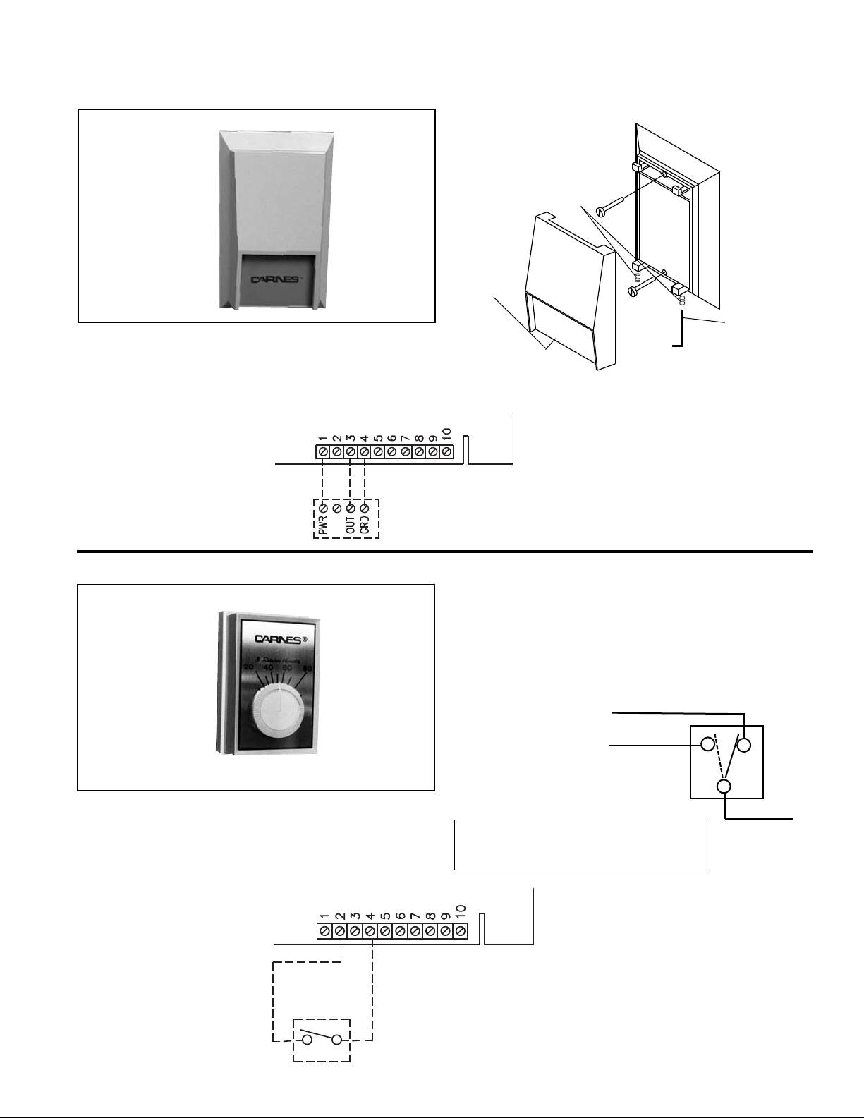
WALL HUMIDISTAT, PROPORTIONAL CONTROL
The wall mounted HXHCG humidistat uses a special sensor
and electronic circuity to modulate the output of the humidifier.
The humidistat automatically adjusts the humidifier output to
match the humidity requirements. This humidistat has a
concealed set-point adjustment with a locking cover. Set-point
range is from 10-90% RH.
Lift cover up
from base
Allen
Screws
Use Allen
wrench to
unlock cover
Unit may be installed on either a flush switch box, or a surface
switch box, or directly on a wall.
Mount with Number 6 screws provided for switch box mounting.
Different screws are required for wall mounting.
RED (N. C.)
BROWN (N . O.)
(To Terminal 2 or 4)
ORANGE (COMMON)
(To Terminal 2 or 4)
RED MAKES TO ORANGE
on a R. H. Rise.
BROWN MAKES TO
ORANGE
on a R. H. Drop.
NOTE: The HXHAA has 6” (152mm) leads and a green
grounding wire for use with non-conducting
conduit.
Mount this humidistat four or five feet above the floor in freely
circulating air of the temperature and humidity about average for
the entire space to be controlled. Avoid locations near hot or
cold air ducts and discharge air from the humidifier. Scale range
is from 10-90% RH. Differential is 5% non-adjustable.
WALL HUMIDISTAT, ON-OFF CONTROL
Model HXHCG
Model HXHAA
Page 8
8
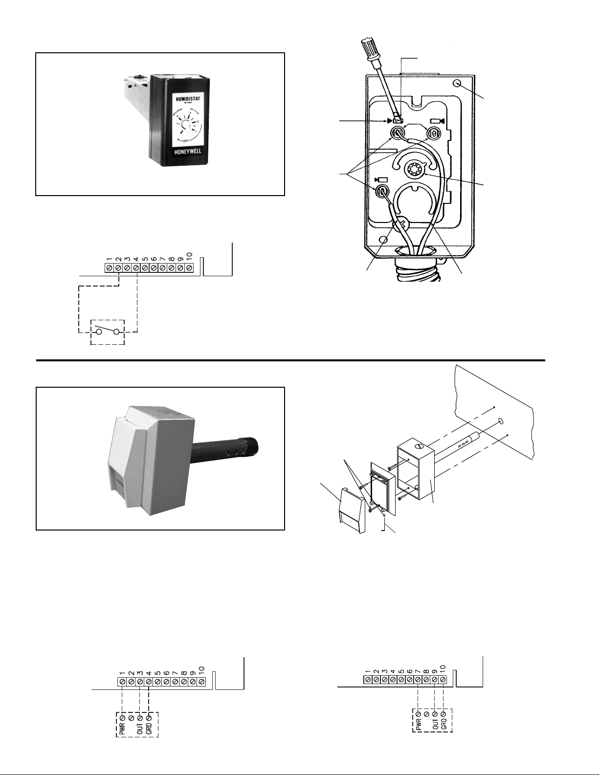
DUCT HUMIDISTAT, ON-OFF CONTROL
This duct mounted humidistat is installed in the return air duct to
sense the humidity level in the area being served. Scale range
is 15-50% RH. Differential is 4-6% non-adjustable.
The control should be located in the duct where it will be affected by normal air flow. The control can
be mounted in any position, but where possible locate it on the side of the duct to make the set-point
adjustment easily accessible.
MOUNTING
HOLES - 2
SET-POINT
ADJUSTMENT
PUSH SCREWDRIVER
IN AND HOLD
PUSH IN
RELEASE - 3
WIRE TO
HUMIDIFIER TERMINAL
2 OR 4
WIRE TO
HUMIDIFIER
TERMINAL 2 OR 4
PUSH IN
TERMINAL - 3
PUSH TO
RELEASE
COM.
DUCT HUMIDISTAT, PROPORTIONAL CONTROL
The model HXHCH can be mounted in either the return air duct
when used to sense the humidity in the area being served or in
the supply duct a minimum of 10 feet downstream of the steam
distributor pipe when used as a high limit control. Set-point
range is 10-90% RH.
Snap-on
plastic
cover
Aluminum housing
DUCT
Allen screws
Use Allen wrench
to unlock cover
Remove any excess insulation from the duct that would prevent
the probe from extending a minimum of 4” (106mm) into the air
stream.
Make a 1-1/2” (38mm) hole in the duct for inserting the probe.
Use a gasket, sealer, or other means to seal the area between
the unit and the duct to ensure proper operation.
WHEN USED TO CONTROL ROOM RELATIVE HUMIDITY
WHEN USED AS HIGH LIMIT HUMIDISTAT
Model HXHAB
Model HXHCH
Page 9
9
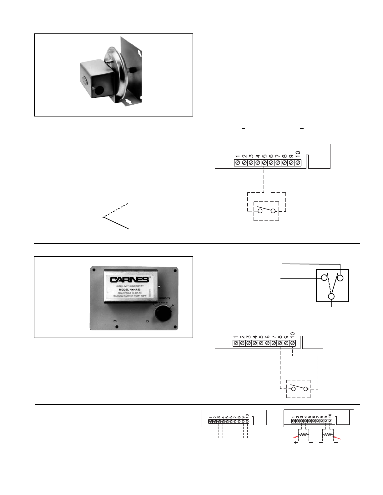
AIR FLOW SWITCH, PRESSURE DIFFERENTIAL TYPE
HIGH LIMIT HUMIDISTAT
EXTERNAL DDC CONTROL SIGNALS
The humidifiers can also accept a 0-10 volt DC signal to
modulate the output of the humidifier. Polarity must be
observed. Input impedance is 20K ohms. If a 4-20 mA input
signal is provided to the humidifier a 470 ohm 1/4 watt resistor
must be installed as shown.
Air flow in the duct may be sensed by using this differential pressure switch. The differential in pressure between the interior of
the duct closes a switch when air is moving. Air pressure
differential as low as .07 w.g. may be sensed with this switch.
Environment:
Ambient Temperature Limits,
Shipping -40 to 140
O
F (-40 to 60OC).
Operating 35 to 140OF (0 to 60OC).
Humidity, 5 to 95% R.H., non-condensing.
Locations, NEMA Type 1 indoor only.
Mounting: In vertical position on any surface free of vibration
N.O. makes on increase of pressure
(N.C.)
(N.O.)
To Terminal 5 or 6
To Terminal 5 or 6 COMMON
•
•
•
On an increase of air pressure to above set-point, common
contact of switch is made to normally open contact. On a
decrease of air pressure to below set-point, common contact of
switch is made to normally closed contact. Avoid locations
where excessive moisture, corrosive fumes or vibrations are
present.
Set-point:
Factory Set, 0.07” (1.8mm) W.C.
Field Adjustable, 0.07 to1” (1.8 to 25.4mm) W.C.
Sensing Element: Neoprene diaphragm.
Adjustment
Note: Units are shipped at minimum set-point.
To increase set-point, turn adjustment screw clockwise.
Adjustable 0.05 +
0.02” to 1.0” (1.25mm +
0.5mm to 25mm) W.C.
To decrease set-point, turn adjustment screw counterclockwise.
The Model HXHAD is available to reduce the potential of
condensation occurring in the supply duct. The control must be
mounted a minimum of 10 feet downsteam of the steam
distributor pipe. Set-point range is 15-95% RH. Differential is
5% non-adjustable.
The HXHAD may be mounted in any position on the outside
surface of the supply air duct where it is exposed to freely
circulating air (horizontal mounting is preferred).
RED MAKES TO ORANGE
on a R. H. Rise
BROWN MAKES TO ORANGE
on a R. H. Drop.
ORANGE (COMMON)
To Terminal 8 or 10
BROWN (N.O.) To Terminal 8 or 10
RED (N.C.)
Model HXAAE
Model HXHAD
0-10 VDC
PROPORTIONAL
SIGNAL
0-10 VDC
PROPORTIONAL
HI-LIMIT
HUMIDISTAT
4-20ma
PROPORTIONAL
HI-LIMIT
HUMIDISTAT
470 OHM
RESISTOR
(BY OTHERS)
470 OHM
RESISTOR
(BY OTHERS)
4-20ma
PROPORTIONAL
SIGNAL
Page 10
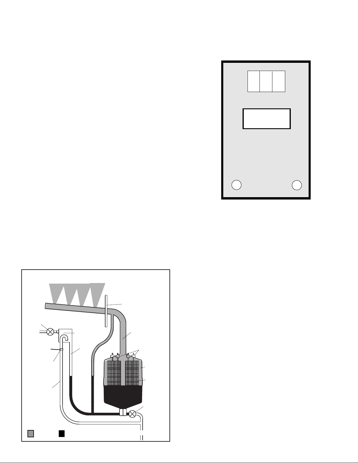
OPERATION
Upon a signal from external controls the circuit board
opens a fill solenoid valve, allowing water to flow across
an air gap into a standpipe. See Figure K. The standpipe
provides a column of water to be fed into the cylinder
using gravity. The air gap prevents back flow into the
water supply and prevents the cylinder from becoming a
pressure vessel. The steam cylinder operates at a
pressure of less than 1/2 psi.
The circuit board also closes a power contactor allowing
current to flow to vertical electrodes sealed inside the
cylinder. Current flows between the electrodes using
minerals in the water as a conductor. The water is heated to boiling and converted to steam, which leaves the
cylinder through the flexible steam hose, which is
connected to the steam distributor pipe.
The circuit board monitors current flow between the
electrodes and automatically opens the fill solenoid valve
when more water is required to maintain the desired
output rate, and closes when the desired rate is reached.
The operation of the drain solenoid valve is automatically
controlled by the circuit board, which responds to any
changes in water conditions and drains the required
quantity of water to provide stable operation and long
cylinder life.
As mineral deposits build up within the cylinder the water
level will slowly rise to uncovered electrode surfaces to
maintain the desired steam output rate. When mineral
deposits have covered all available electrode areas,
current flow will be reduced to a level when the desired
steam output cannot be reached and the service light will
signal the need for maintenance. When the cylinder is
filled with minerals it is easily changed to less than five
minutes.
STEAM
DISTRIBUTOR
PIPE
STEAM
HOSE
FROM POWER
CONTACTOR
CYLINDER
VERTICAL
ELECTRODES
DRAIN
SOLENOID
VALVE
TO DRAIN
STEAM
WATER
AIR GAP
FILL
SOLENOID VALVE
NON CONTACT
HIGH WATER
SENSOR
STAND
PIPE
OVERFLOW
TUBE
Figure K
FRONT PANEL DISPLAYS & CONTROLS
The display on the front panel of the humidifier cabinet
contains the “On-Off-Drain” switch, the LCD digital
display and the “Power” and “Service” LED’s.
“ON-OFF-DRAIN”
In the “On” position the humidifier will operate if all
controls are calling for humidity. The “Off” position is used
for seasonal shut down if desired. The “Drain” position is
used to drain water from the steam cylinder for
maintenance. The fill solenoid valve opens whenever the
drain is activated to reduce the drain water temperature.
DIGITAL DISPLAY
This LCD display shows the steam output rate during
normal operation. The display is factory set for pounds
per hour.
“SERVICE” LED
This LED is on whenever actual steam output is less than
50% of set-point. Both “Power” and “Service” may be
monitored remotely if desired. See “External Monitoring”
for additional information.
DIAGNOSTIC DISPLAY PANEL
PUSH BUTTONS
“Mode” button selects “Normal Operation”, “Display
Demand %”, “Set Max Output” and “Calibration”. “Enter”
button is used with “Mode” button to reset maximum
steam output.
“MODE”
“Normal Operation” shows steam output rate in pounds
per hour on the digital display.
ON OFF DRAIN
STEAM OUTPUT
POWER
SERVICE
Figure L
10.0
10
Page 11
11
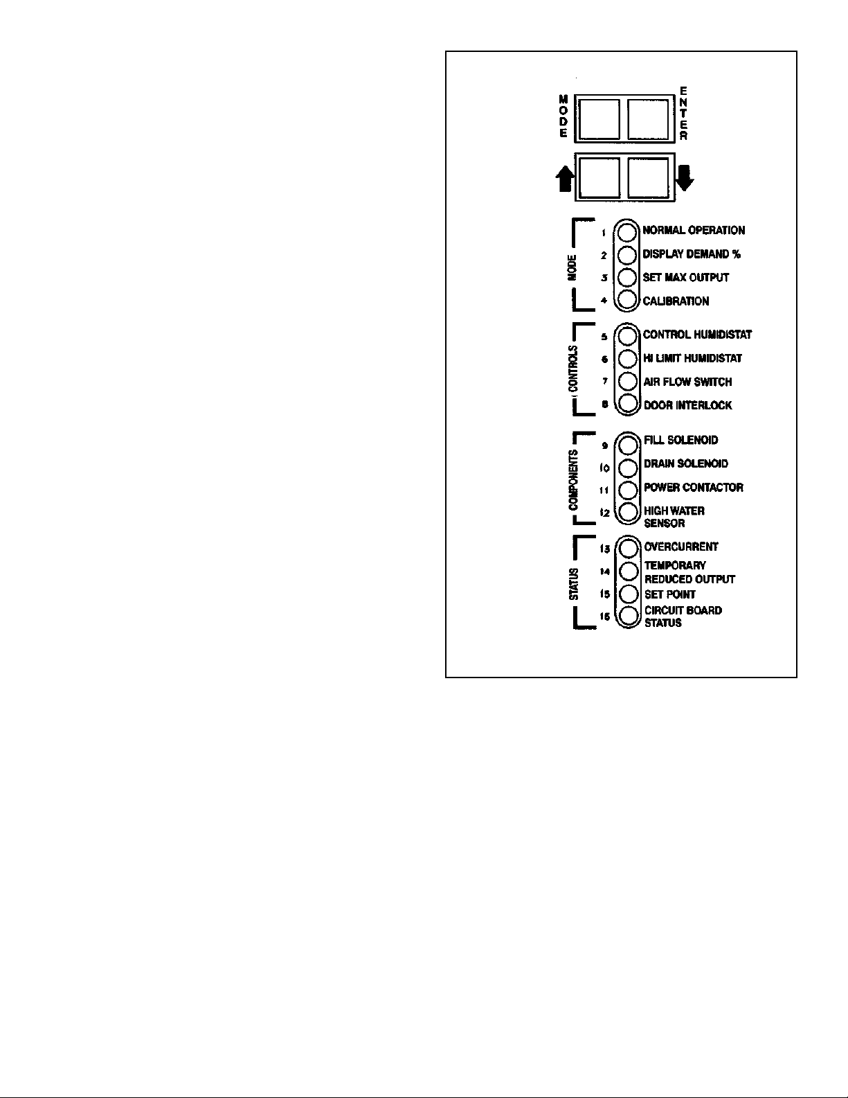
“Display Demand %” is selected by pressing the “Mode”
button once. The digital display will then show the %
demand from the humidistat. If an on-off type humidistat
is used the display will read approximately “100”. If an
proportional humidistat is used the display will show the
percent demand from 0 to 100%. For example if the input
voltage between terminals 3 and 4 is 8 volts DC the
display would indicate “80”.
“Set Max Output” is selected by pressing the “Mode”
button once from “Display Demand %”. The steam output
may be set to a new maximum by first pressing “Enter”
and then pressing the UP or DOWN buttons. When the
desired maximum rate is shown on the digital display
pressing the “Enter” again sets the value into the
memory of the circuit board. The steam output is normally left in the factory set maximum capacity and only
limited if necessary to prevent condensation in the duct.
“Calibration” is selected by pressing the “Mode” button
once from “Set Max Output”. The digital display then
shows a four-digit code indicating the voltage and
maximum capacity of the humidifier. See Electrical Data
Table for code numbers. Pressing “Mode” again returns
to “Normal Operation”. The humidifier will automatically
return to “Normal Operation” after approximately five
minutes.
“CONTROLS”
Separate LED’s indicate that a signal is being received by
the humidifier to operate. An unlit LED indicates that the
specific control is not calling for humidity. All four LED’s
must be on before the humidifier will operate.
“Control Humidistat” LED lights if an on-off humidistat
connected to terminals 2 and 4 is calling for humidity. It
will also be on if a voltage from a proportional humidistat
is connected to terminals 3 and 4 and the signal is above
3 volts DC. A 10-volt DC signal will call for maximum
output and modulate proportionally down to 2 volts DC.
The humidifier will be off below 2 volts DC.
“High Limit Humidistat” LED lights if an on-off high limit
humidistat is connected to terminals 8 and 10 and is
allowing the humidifier to operate. It will also be on if an
voltage from a proportional high limit humidistat is connected to terminals 9 and 10 and the signal is above 3
volts DC. A 10-volt DC signal will call for maximum output and modulate proportionally down to 2 volts DC. The
humidifier will be off below 2 volts DC. If a high limit
humidistat is not used, a jumper must be installed
between terminals 8 and 10.
“Air Flow Switch” LED lights if an air flow switch is
connected to terminals 5 and 6 and is allowing the
humidifier to operate. If an air flow switch is not used, a
jumper must be installed between terminals 5 and 6.
“Door Interlock” LED lights if the door interlock switch has
been activated by pulling the button out for temporary
manual operation or closing the door.
Figure M
“COMPONENTS”
“Fill Solenoid” LED lights whenever the circuit board is
sending 24 volts to the fill solenoid valve. The fill solenoid
will cycle as necessary to provide the proper amount of
water to operate. The fill solenoid is also open whenever
the drain solenoid is activated to mix cooler water to lower
the drain water temperature.
“Drain Solenoid” LED lights when the circuit board is
sending 24 volts to the drain solenoid valve. The valve is
opened to drain some of the high mineral content water
from the cylinder and replace it with fresh water. This is
not a preset repetitive cycle but is automatically
determined by the circuit board and only occurs when
necessary to maintain proper mineral content in the
steam cylinder. The drain solenoid also will open if the
circuit board detects that high current is flowing to the
steam cylinder. Opening the drain solenoid will lower the
water level in the cylinder and reduce the current.
Page 12
12
“Power Contactor” LED lights when the circuit board is
sending 24 volts to the power contactor to supply
primary voltage to the cylinder electrodes.
“High Water Sensor” LED lights when water has been
detected by the sensor located on the overflow tube. This
sensor detects water flowing through the tube without
making physical contact with the water. When overflow is
detected, the fill solenoid valve is temporarily prevented
from opening. The set-point if temporarily reduced to
prevent water from reaching the top of the steam cylinder.
The LED labeled “Temporary Reduced Output” will come
on. This cycle may be repeated several times if the
incoming water is very low in mineral content. As
minerals build up in the water in the cylinder increasing its
conductivity the set-point will gradually increase until the
full output is reached. The length of this process will vary
depending on the conductivity of the incoming water and
may require several hours under certain conditions.
“STATUS”
“Overcurrent” LED lights if the circuit board has detected
over-current in the steam cylinder and has been unable to
reduce the current by operating the drain solenoid valve.
The humidifier is placed in standby mode to prevent
unsafe operation. The “Service” LED on the front panel
will also be on to signal this condition. The “Overcurrent”
LED is usually an indication that the drain solenoid valve
or related plumbing is restricted and requires cleaning. A
defective valve could also cause this failure.
“Temporary Reduced Output” LED is described in the
Components” section of this manual. This light may also
be on with the “Service” LED at the end of steam cylinder
life.
“Set-point” LED lights whenever the actual steam output
is at or above the set-point of the humidifier or when the
demand from a proportional humidistat is reached. This
light will be on and off during the normal operating cycle
of the humidifier as water fills the steam cylinder and is
boiled away and filled again.
“Circuit Board” LED pulsing is normal and indicates that
the microprocessor on the board is functioning.
START UP & OPERATION
INITIAL START UP
While the external disconnect switch is off, be sure that
the terminal connectors on the top of the cylinder are
firmly secured and pushed completely down over the pins
in the cylinder.
1. Open all water supply valves external to the
humidifier.
2. Turn external disconnect switch on.
3. For safety, the door interlock disconnects power to
cylinder when the door is opened. Humidifier may be
temporarily operated for service purposes by pulling
out white button.
CAUTION:
HIGH VOLTAGES AND
HOT SURFACES ARE PRESENT.
4. Turn “On-Off-Drain” switch to “On” position. Green
“On” LED should now be on.
5. Unit will now begin to operate if external controls are
calling for humidity. See “Controls” for details.
6. As water slowly fills into cylinder the digital display will
begin to increase when water contacts electrodes.
7. The “Service” LED may come on until sufficient water
has entered cylinder to provide 50% of set-point.
8. Water will continue to fill until output is 10% above
set-point. If water reaches top of cylinder before setpoint is reached “High Water Sensor” will be activated
and fill will stop. See “High Water Sensor” for details.
9. When starting with a new cylinder and fresh water the
fill and drain solenoid valve may cycle for brief periods
until water has come to a complete boil.
10.In areas with low conductivity water full output may
not be reached until humidifier has conditioned the
water by repeated cycles of filling, boiling and refilling.
The length of this process will vary but may require
several hours under certain conditions.
Page 13
13
AUTOMATIC DRAIN CYCLE
The electronic circuit board automatically controls the
operation of the drain solenoid valve to react to two situations:
CONTROLLING MINERAL CONTENT:
1. When current reaches 10% above set-point the fill
solenoid valve closes and water gradually boils away
in the cylinder. Because the quantity of water covering
the electrode surface is being reduced, current slowly
falls.
2. A timer in the electronic circuit board starts when
current drops 95% of set-point.
3. The timer runs for a predetermined time or until 90%
of set-point is reached.
4. If current changes too rapidly during the drop from 95
to 90% it indicates that a drain is necessary to reduce
the mineral concentration of the water.
5. If current changes slowly it indicates that mineral
concentration is satisfactory and a drain is not
necessary.
6. The circuit board opens the fill solenoid valve to refill
the cylinder to proper levels.
REDUCING OVERCURRENT
1. If current to the electrodes in the cylinder reaches
more than 20% above the set-point the drain solenoid
valve opens.
2. Draining water from the cylinder reduces current by
covering less electrode surface.
3. If current is successfully reduced to acceptable levels
normal operation continues.
4. If current is not reduced because of mineral blockage
in the drain lines or solenoid valve the power
contactor will be opened for approximately 15 seconds
while the drain valve is open.
5. If current is not reduced the cycle is repeated 8 more
times. If still unsuccessful unit is placed in standby
mode and “Overcurrent” LED lights.
ADJUSTING STEAM OUTPUT RATE
To reset the maximum output value from the factory
preset maximum follow the steps below.
1. Press the ‘Mode” button until “Set Max Output” LED
lights.
2. Press “Enter” once.
3. Press either UP or DOWN buttons until desired new
maximum setting is shown on the digital display.
4. Press “Enter” once.
5. Press “Mode” until “Normal Operation “LED” lights.
ROUTINE MAINTENANCE
REPLACING THE STEAM CYLINDER:
Normal indication to replace cylinder is “Service” light on
after extended period of operation (500-2000 hours).
1. Turn “On-Off-Drain” switch to “Drain” and completely
drain water from cylinder.
2. Turn “On-Off-Drain” switch to “Off”. Turn power
disconnect switch ahead of humidifier off.
3. Remove terminal connectors from top of cylinder by
twisting and pulling straight up.
4. Remove steam hose and open cylinder retaining
band.
5. Remove cylinder by turning counter-clockwise.
6. It is advisable to check drain lines and solenoid valve
and clean if necessary before replacing cylinder.
7. Install new cylinder by using Teflon tape or pipe
dope.
8. Reconnect hose, retaining band and terminal
connectors. Turn on all power to humidifier.
CLEANING THE WATER STRAINER:
The water strainer may require cleaning if “Service” and
“Fill Solenoid” LED’s are on and water is not flowing or is
flowing slowly.
1. Turn “On-Off-Drain” switch to “Off”. Turn off power
disconnect switch ahead of humidifier.
2. Shut off water valve ahead of the unit. Disconnect
flexible tube, brass fitting, and electrical connections
from fill valve. Remove fill valve by loosening two
mounting nuts.
3. Strainer is located inside threaded connection on fill
solenoid valve.
4. Rise strainer screen. Do not attempt to remove
screen from valve body.
5. Replace valve and reconnect brass fitting, flexible
tube, and electrical connections. Turn on all power
to humidifier.
CAUTION:
HIGH VOLTAGES AND
HOT SURFACES ARE PRESENT. ALLOW
CYLINDER TO COOL BEFORE HANDLING.
W
ARNING:
THE ABILITY TO SAFE-
LY PERFORM MAINTENANCE ON THIS
EQUIPMENT REQUIRES TRAINING,
MECHANICAL SKILLS AND TOOLS. IF
YOU DO NOT POSSESS THESE, DO NOT
ATTEMPT TO PERFORM MAINTENANCE
ON THIS EQUIPMENT. FAILURE TO FOLLOW THIS WARNING COULD RESULT IN
DAMAGE TO THIS EQUIPMENT, SERIOUS
PERSONNEL INJURY, OR DEATH.
Page 14
6. If water is near the top of the cylinder and overflow is
occurring the cylinder may be in need of replacement.
SYMPTOM: WATER DOESN’T FILL INTO CYLINDER
1. Confirm that four LED’s on “Control” section of
diagnostic display are on.
2. If all four LED’s are not on consult “Controls” info.
3. If all four LED’s are on check LED labeled “Fill
Solenoid”. If LED is on, check 24 V AC at coil of fill
solenoid valve. If 24 V AC is present water should be
flowing. Be sure all shut off valves ahead of the unit
are open.
4. If water is available check strainer on solenoid valve
for sediment. Clean if necessary.
5. If 24 V AC is present and strainer is clean solenoid
valve may be defective.
6. If “High Water Sensor” LED is on the “Fill Solenoid”
LED and valve will be off for one minute. See “High
Water Sensor” for details.
SYMPTOM: DRAINS CONTINUOUSLY
1. The most common cause is to have a piece of
mineral in the drain solenoid valve that prevents the
valve from closing properly. Simply cycling the “OnOff-Drain” switch back and forth between “On” and
“Drain” may dislodge the sediment. In extreme cases
it may be necessary to disassemble drain lines to
clean them out.
2. The “Drain Solenoid” LED indicates if the electronic
circuit board is sending 24 V DC to the valve. If the
LED is off but 24 V is present at the drain solenoid coil
the circuit board may be defective.
SYMPTOM: WATER IN THE DUCT
Note: This is usually an installation problem. The first
step is to determine whether water is spitting from the
steam distributor pipe or if steam is condensing on some
object downstream from the steam distributor pipe.
If water is spitting from the steam distributor pipe there
may be several causes.
1. The steam hose and condensate return line MUST
have continuous slopes without any sags or low areas
where water could accumulate. If water accumulates
in the steam hose it may be suddenly pushed into the
distributor pipe and the condensate return line may be
unable to handle the volume.
2. Make sure that the condensate return line is not
restricted. Areas where the hose bends or where it is
tied using cable ties are often the problem.
3. The distributor pipe must be installed so that far end
of the distributor pipe is higher than the incoming end
where the condensate return connection is located.
The mounting plate on distributor pipes should be
mounted on a plumb surface to provide proper pitch.
4. If the condensate return line has a drop of less than
12” from the distributor pipe to the top of the humidifi
er cabinet it may be better to route to the drain below
the unit rather than connecting at the top of the cabinet.
TROUBLE SHOOTING
SYMPTOM: NONE OF THE LIGHTS ARE ON
1.
Verify that voltage being supplied to unit is same as
listed on rating label on front left hand corner of
cabinet.
2. Verify that 24 V AC is being supplied by power trans
former by taking voltage reading at terminal strip J20
on two red wires coming from secondary of
transformer. J20 is located on the top right hand
corner of the electronic control board.
3. If 24 V AC is not present reset the overload located on
the transformer and recheck.
4. If 24 V AC is present the electronic control board may
be defective.
SYMPTOM: “SERVICE” LIGHT IS ON
Normal reason is time for steam cylinder replacement
caused by gradual mineral build up inside plastic cylinder.
Water gradually rises to cover unused electrode surfaces
until output begins to decline. If cylinder has been
operating for an extended period of time and water is high
replace with new cylinder.
If cylinder is not at end of life other items to be checked:
1. Check “Overcurrent” LED. If on, switch “On-Off-Drain”
switch to “Drain”. Verify water is draining freely from
cylinder. Clean internal drain lines and drain solenoid
valve if necessary.
2. If “Overcurrent” LED is off, check “Fill Solenoid” LED.
If on, verify that water is flowing from fill solenoid valve
and then into standpipe connected to bottom of steam
cylinder. If water is not flowing verify that all shut off
valves ahead of unit are open. Check water strainer in
fill solenoid valve and clean if necessary.
3. If water is flowing through fill solenoid, and standpipe
but not into the steam cylinder check to determine if
drain solenoid valve is partially open. See “Drains
Continuously” section on next page.
4. If water is not flowing check “High Water Sensor” LED.
If LED is on, wait a minimum of one minute. Every 60
seconds the high water sensor resets and rechecks
for water flow through the overflow tube. The sensor is
touch and proximity sensitive so touching the wire or
sensor will cause it to activate.
5. If water is flowing through the overflow tube it can be
caused by an obstruction blocking the inlet to the
cylinder fitting. If water is low in the cylinder but over
flow is occurring cleaning of the plumbing is recommended.
WARNING:
THE ABILITY TO SAFELY PERFORM MAINTENANCE ON THIS
EQUIPMENT REQUIRES TRAINING,
MECHANICAL SKILLS AND TOOLS. IF
YOU DO NOT POSSESS THESE, DO NOT
ATTEMPT TO PERFORM MAINTENANCE
ON THIS EQUIPMENT. FAILURE TO FOLLOW THIS WARNING COULD RESULT IN
DAMAGE TO THIS EQUIPMENT, SERIOUS
PERSONNEL INJURY, OR DEATH.
14
Page 15

3. A defective drain solenoid valve will prevent proper
draining. The solenoid should be checked to verify
that it moves freely when 24 V DC is applied to the
coil. When placed in the “Drain” position both the drain
and fill valves open and it is very important the water
level falls in the cylinder even with the fill solenoid
open.
4. Insufficient flow of incoming water will cause arcing by
causing low water levels. Since an automatic drain is
not initiated until set-point is reached a drain will not
occur if the flow rate is too low. Therefore, if low water
pressure at the humidifier (below 20 psi) or a clogged
water strainer restricts the flow of water, arcing will
result.
5. High back pressure, caused by an obstruction in the
steam hose, prevents fresh water from entering the
cylinder and results in arcing. Care must be taken to
prevent kinking of steam hose when making bends.
6. Excessive lengths of steam hose cause low water
levels and arcing.
7. Frequent cleaning of the steam cylinder by removing
and flushing or by striking the side of the cylinder
potentially dislodges flakes that can build up a “dam”
in the drain lines. It is not recommended that the
cylinder be removed except for replacement.
8. Chemicals should not be used to attempt to prevent
mineral build up in the cylinder or to dissolve minerals
that accumulate. Chemical treatment may affect
conductivity. Only untreated tap water is
recommended for use in the humidifier.
5. If the condensate return line is connected to fitting at
the top of the humidifier cabinet make sure that traps
have not been installed in the return line. A trap is only
needed if the return line is routed to a separate drain
and it is necessary to prevent steam from being dis
charged from the line.
If water is condensing on an object in the duct or on the
duct itself it will be necessary to take other steps.
1. The distributor pipe must be a minimum of 3 feet
upstream from any elbow, split, coil, turning vane,
grille or diffuser. The lower the air temperature is in
the duct the further upstream the pipe must be
located. If the air temperature is 60°F it may be
necessary to have 10 feet between the pipe and any
obstruction.
2. If it is not possible to have the required distance from
the distributor pipe to an obstruction a drain pan may
be required to accommodate the water.
3. It may be that air in the duct simply can’t hold the
volume of steam that is being added. Normally the
only practical solution is to reduce the steam output of
the humidifier, as it is usually not feasible to increase
the air temperature or quantity. See “Adjusting Steam
Output Rate” for procedure.
SYMPTOM: ARCING IN THE STEAM CYLINDER
An occasional arc is not a problem. When a cylinder is
restarted after a long period of off time arcing may occur
as pieces of mineral flake off the electrode surface.
During a drain cycle arcing may occur if water is very low
in the cylinder. Arcing is a problem if it occur frequently or
if it causes dark brown or red discoloration in the cylinder.
The dark deposits are caused by deterioration of
electrode material and must be prevented. Arcing may be
caused by several conditions:
1. Incoming water may have high conductivity.
Conductivity, the ability to conduct current, is
measured in “Micromhos”. In an electrode type
humidifier there are maximum values of conductivity
that may be used in the humidifier. It is very unusual
for any naturally occurring water to have conductivity
that is too high for operation. If water is treated by a
water softener its conductivity will be higher than
untreated water. As it is boiled away its conductivity
also increases at a higher rate than untreated water.
Softened water may be too high in conductivity to
operate without arcing.
2. Drain lines within the humidifier that have become
restricted by mineral deposits prevent proper drain
rates. This causes minerals to concentrate inside the
cylinder, which in turn causes low water levels. Low
water levels cause arcing. Drain lines should be
inspected when cylinders are changed and
thoroughly cleaned if necessary.
15
Page 16
16
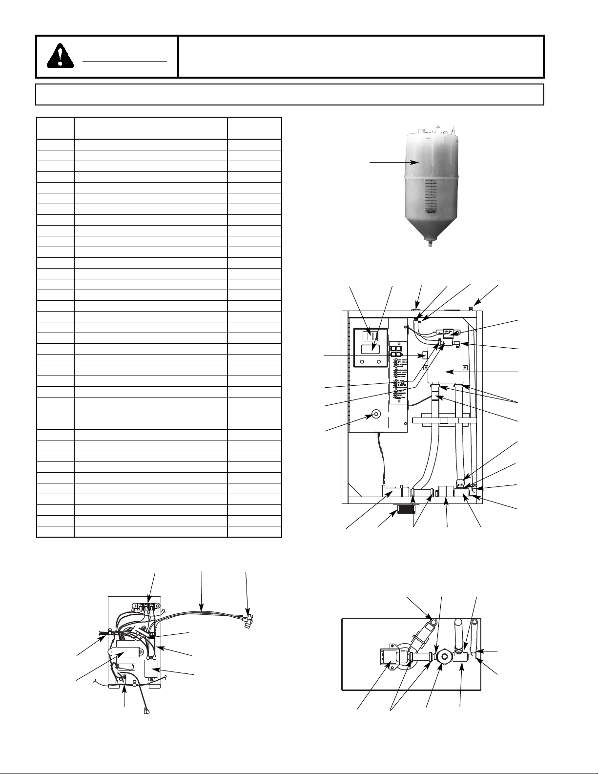
Item
Number Description Part Number
1 Steam Cylinder (120V) HXCBAX220
1 Steam Cylinder (230V) HXCBAX380
2 Circuit Board with LCD Display H-690-0080
3 Water Inlet Fitting, 1/4” NPT H-999-4055
4 Barbed Connector, 1/4” NPT (Straight) H-999-4057
5 Metal Hose Clamp H-999-7166
6 Plastic Fitting H-999-4062
7 Fill Solenoid Valve H-999-7447
8 Barbed Connector, 1/8” NPT (Elbow) H-999-4059
9 Molded Fill Cup H-690-4139
10 Plastic Hose Clamp H-999-7161
11 Barbed Connector, 3/8” NPT (Straight) H-999-4058
12 Plastic Hose Clamp H-999-7162
13 Barbed Connector, 3/8” NPT (Elbow) H-999-4060
14 Brass Tee, 3/8” NPT H-999-4061
15 “AX” Cylinder Connector H-998-5703
16 Sink Fitting H-999-8676
17 Drain Solenoid Valve H-999-7448
18 High Level Sensor Including Overflow Tube H-690-1352
19 Door Interlock Switch H-801-7801
20 Barbed Connector, 1/8” NPT (Straight) H-999-4056
21 Plastic Cap H-999-8310
22 On-Off-Drain Switch H-999-7330
23 Plastic Elbow H-999-9690
24 Terminal Block H-999-7992
25 Power Wire with Cylinder Terminal H-690-2991
Connector
26 Terminal Connector - Red H-998-1256
27 Current Sensing Transformer H-999-9429
28 Power Wire H-690-2990
29 Power Contactor (Relay) H-999-6126
30 Bridge Rectifier H-999-6127
31 Power Transformer H-998-9537
32 Low Voltage Wiring Harness H-998-7008
* Air Gap Drain Fitting H-690-0176
* Door Lock with Key H-999-9141
* Key for Door Lock H-999-5106
POPOWERWER
STEAM OUTPUTSTEAM OUTPUT
SERSERVICEVICE
OFFOFF
ONON
DRAINDRAIN
11
12
13
17 16 10 15 14
19
20
23 11 10
24 26
21
5
18
1
2
22
3 4
5
6
10
8
9
10
7
POWER
STEAM OUTPUT
SERVICE
OFF
ON
DRAIN
17 10 15 14
12
13
25
32
31
27
28
29
30
Model HRAA - Replacement Parts
W
ARNING:
* Not Shown
UNAUTHORIZED MODIFICATION OF THIS HUMIDIFIER OR USING UNAUTHORIZED REPLACEMENT PARTS MAY CAUSE MALFUNCTION WITH RISK OF
SERIOUS PERSONAL INJURY AND WILL VOID ALL PRODUCT WARRANTIES.
Page 17
READ AND SAVE THESE INSTRUCTIONS
ADDENDUM (1) TO FORM #’S - 16799, 16828, 16789, 16831
INSTALLATION, OPERATION AND MAINTENANCE INSTRUCTIONS
CARNES COMPANY 448 S. Main St., P. O. Box 930040, Verona, WI 53593-0040 Phone: (608)845-6411 Fax: (608)845-6470 www.carnes.com
In an attempt to improve quality and ease of maintenance, certain performance enhancements have been added
to the Microprocessor chip, located on the back side of Circuit Board H-690-0080. The new version installed as
of the week of May 19, 2008 is 1.5. THis version will replace all previous versions of the “G” model design series.
It is also available as a replacement part (H-998-5928).
“SET-POINT” LED:
(Current 1.5 Version Microprocessor)
Flashing LED indicating an error condition where the drain valve is stuck open, typically due to large flakes or chunks of
solid mineral deposits broken free from the cylinder and lodged within the valve body. This program will attempt corrective
action and, if unsuccessful, will shutdown the unit and signal user.
CORRECTIVE ACTION TO TAKE: Clean or replace solenoid valve.
“OVER-CURRENT” LED:
(Current 1.5 Version Microprocessor)
Steady LED indicating an inoperative drain system, due to plugging with mineral deposits or inoperative drain valve
mechanics. Flashing LED will no longer be included in fault indications.
CORRECTIVE ACTION TO TAKE: Clean or replace drain solenoid valve and/or clean out drain plumbing.
“HIGH WATER” LED:
(Current 1.5 Version Microprocessor)
Flashing LED distinguishes between overflows caused by abnormal operating conditions (excessive back-pressure,
drain valve stuck closed, aged cylinder) versus overflows caused by normal, allowable conditions (start-up with low
conductivity water).
CORRECTIVE ACTION TO TAKE: If cylinder has been in use for a period of time, replace cylinder. Check and clean or
replace as necessary the drain solenoid valve. Check and clean as necessary the drain plumbing.
If cylinder is new, check the following and take corrective action as shown. Back-pressure can be fixed by removing any
elbows or sags in hoses, or reduce the length of hose between humidifier and distribution pipe by moving them closer
together.
OTHER PROGRAM CHANGES:
(Version 1.5)
The fill delay at each overflow detection for past and current microprocessor version is as follows: 1.1 Version is 1 minute,
1.2 Version is 10 minutes & 1.3 Version is 5 minutes. 1.5 Version is 5 minutes like 1.3 & 1.4 and will now be the current
version of all “G” model design series. It can also replace any previous versions as necessary.
DISPLAY DEMAND % FOR CONTROL HUMIDISTAT & HIGH LIMIT HUMIDISTAT:
(Version 1.5)
To display demand from High Limit Humidistat, in addition to control humidistat, which previous version did not provide.
When user selects Display Demand % mode, the following will be displayed as XX.YY: XX = Demand from control
humidistat in %, YY = Demand from high limit humidistat in %. (the highest value that the control humidistat or high limit
humidistat will show is 99. 99 will be defined as 100% value. 2 is the maximum characters available for each control value
on the digital LCD).
New program feature available with 1.5 version microprocessor chip. In the event of humidifiers being used in areas where
the potable tap water supply is questionable, based on bad water, high hardness, high mineral content, etc, the 1.5 version offers the following. With the input of a specific digital operating code in the software of the circuit board, a pulsing
drain cycle can be activated whenever a self correcting cycle is initiated on the low side of operating cycle during boil down.
Contact technical rep for details.
FORM 16833-B
 Loading...