

Page 1
READ AND SAVE THESE INSTRUCTIONS
ELECTRONICALLY CONTROLLED STEAM HUMIDIFIER
DESIGN SERIES HB
INSTALLATION, OPERATION
AND MAINTENANCE MANUAL
CARNES COMPANY, 448 S. Main St., P. O. Box 930040, Verona, WI 53593-0040 Phone: 608/845-6411 Fax:608/845-6470 [email protected] http://www.carnes.com
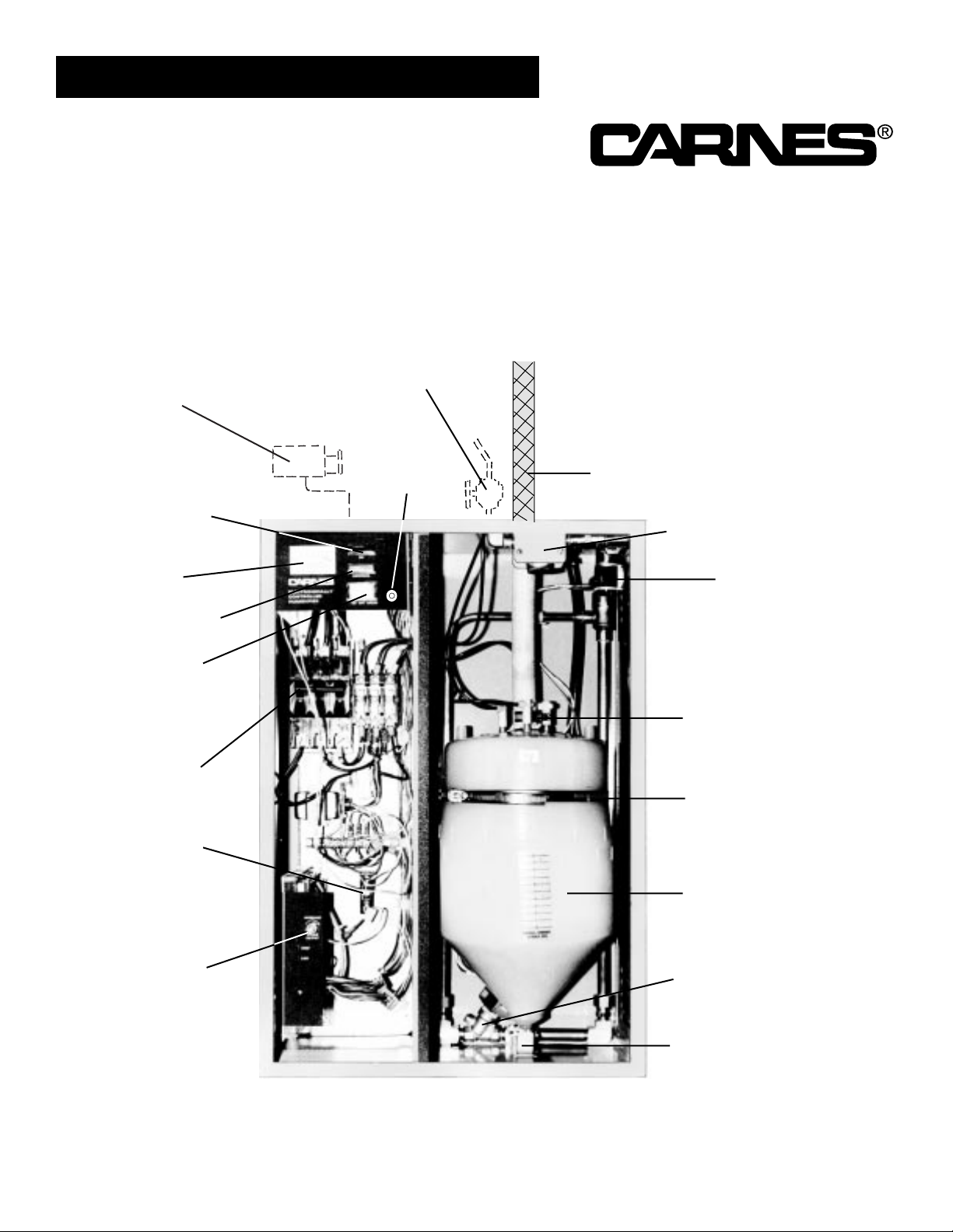
External Disconnect
or Circuit Breaker
(Not Provided by Carnes)
Water Shutoff Valve
(Not Provided by Carnes)
FORM 16632-B
Steam Hose
Water Strainer
Fill Solenoid
Valve
Door
Interlock
“On” Lamp
Steam Output
Rate Meter
“Abnormal” Lamp
“On-Off-Drain”
Switch
Magnetic
Overload
Switch
Low V oltage
Fuse
Steam Output
Control
Hose Clamp
Cylinder
Retaining
Band
Steam
Cylinder
Drain Solenoid
Valve
Brass Cylinder
Fitting
Photo A
MODEL HBDA SHOWN
Page 2

INSTALLATION
UNPACKING AND INSPECTION
1.
2.
3.
4.
5.
A manila envelope attached to the outside of the cabinet contains the following items:
A. Installation instr uctions
B. One cabinet key
Open the cabinet and check for concealed shipping
damage. Report any damage immediately to the carrier who delivered shipment.
The following components are packed in a shipping
carton for connection when installing humidifiers:
A. Distributor pipe
B. Steam hose
C. Condensate return line
Optional accessories may be packed with the cabinet
or in the same shipping carton. Large accessories
ship in separate cartons.
Inside the cabinet are the following items:
A. Steam hose clamps
B. Condensate return line clamps
C. Air gap drain fitting
1.
2.
3.
Remove the large nut and plastic gasket located on
the fitting on the bottom of the cabinet (Photo B). The
nut and gasket may be used with standard type drain
fitting if an air gap drain fitting is not required by local
codes.
Connect the air gap drain fitting to the cabinet drain
connection. Drop plastic insert into the top of the air
gap drain fitting before connecting. It may be necessary to cut off some of the air gap fitting depending on
available space.
Connect the drain or air gap fitting to S or P Trap.
Note: If the drain water pump accessory package is
used, follow instructions included with the drain water
pump package.
MOUNTING THE HUMIDIFIER
Mount the humidifier cabinet securely on a level and
plumb surface near the ductwork. Allow 6” or more on
each side for proper ventilation and a minimum of 16”from
the bottom of th cabinet to the floor to allow space for the
drain connection. The humidifier must never be mounted
outside or where it may be exposed to freezing temperatures. Maximum operating weights for the humidifier are
shown below.
TABLE 1
MAXIMUM OPERATING WEIGHT
MODEL WEIGHT (Pounds)
HBDA 85
HBEA 130
HBFA 175
HBGA 105
HBHA 185
HBJA 260
WATER SUPPLY CONNECTION
Use ordinary tap water (20 to 120 psi) — DO NOT use hot
or deionized water. A 3/8” FPT fitting is provided at the
top of the humidifier for connection to tap water supply. A
shut-off valve, not provided by Car nes, must be installed
just ahead of this fitting.
DRAIN LINE CONNECTION
Drain Line
Connection
Photo B
MODEL HBDA SHOWN
TYPE OF WALL
6 FASTENERS REQUIRED (Models HBDA, HBEA & HBFA)
8 FASTENERS REQUIRED (Models HBGA, HBHA, & HBJA)
Wood Studs or Solid Wood 1/4” Lag Screws
Hollow Plaster 1/4” Molly Bolts or Toggle Bolts
Sheet Metal 1/4” Thread Forming Screws
Cement or Masonery 1/4” Lead Type Anchor and Bolts
FASTENER RECOMMENDATION
Page 3
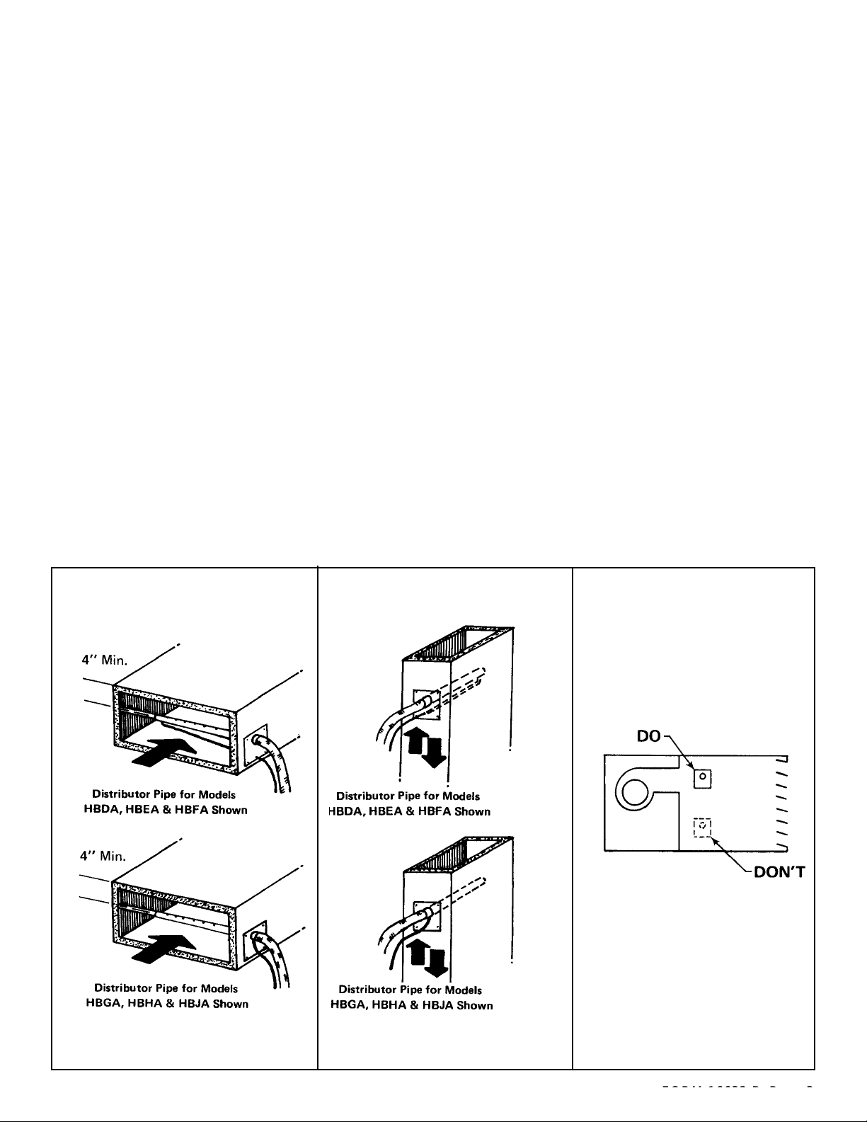
1.2.Steam distributor pipe must be mounted on a plumb
surface. When mounted on a plumb surface the standard distributor pipe for Models HBDA, HBEA and
HBFA pitches downward and is inclined upward for
Models HBGA, HBHA and HBJA. This is required so
the condensate which forms in the distributor pipe will
drain to the return line and back to the unit.
Steam distributor pipe should be mounted in the duct
to insure even distribution of steam across the center
portion of the duct (Figure A). The condensate return
line must always be kept on the bottom. A minimum
clearance of 4” must be maintained between the duct
and distributor pipe. The steam distributor pipes are
designed with a steam outlet hole pattern which gives
even distribution, y et k eeps steam a w a y from the sides
of the duct.
The standard humidifier steam distributor pipe must
never be installed v ertically. If air flows are vertical, the
steam distributor pipe should be installed horizontally
(Figure B).
The steam distributor pipes should be installed in the
supply air stream, downstream of the fan (Figure C).
When installed in packaged units (central station air
handlers, multizone units, make-up air units, etc.) the
distributor pipe should be mounted just downstream of
the fan discharge in the primary air stream.
INSTALL STEAM DISTRIBUTOR PIPE
3.
4.
5.
6.
In multizone applications it is preferable to have a separate humidifier serving each zone. However, steam
can be introduced into the hot deck upstream of the
zone dampers. In this case, good distribution of steam
across the entire hot deck is very important.
It is preferable to locate the steam distributor pipes
downstream from any obstructions in the ductwork so
that air can absorb moisture before it impinges on a
surface and accumulates. There must be a minimum
of three feet between the steam distributor pipes and
any fans, coils , filters , z one dampers, elbo ws or outlets
which may be installed downstream of the distributor
pipe. Howe v er, in all cases, the steam distributor pipes
should be located as far upstream from any such
obstruction as possible.
An adhesive backed template is provided for each distributor pipe. This provides the hole pattern for mounting each steam distributor pipe. Using the template(s),
cut necessary holes in ductwork at desired location of
distributor pipe.
Inset any distributor pipe into duct and secure tightly
with four sheet metal screws, not provided by Car nes.
Special distributor pipes are shipped with specific
instructions on how to mount them.
If the accessory fan distribution unit is to be used, follow the instructions included with the unit.
INSTALLATION
Figure A
Figure B Figure C
Page 4
INSTALLATION
CONNECTING THE STEAM HOSE
Refer to Figures D, E and F
EACH CYLINDER REQUIRES SEPARATE STEAM
HOSE, CONDENSATE RETURN LINE, AND STEAM
DISTRIBUTOR PIPE.
COPPER OR BRASS TUBE IS THE ONLY ACCEPTABLE SUBSTITUTE FOR CARNES STEAM HOSE OR
CONDENSATE HOSE
1.
2.
The steam hose should be installed so there is a continuous rise from the humidifier to the distributor pipe.
Support the steam hose at intermediate points to prevent dips or pockets. If it is necessary to mount the
distributor pipe below the top of the humidifier , a “T”fitting must be installed at the lowest point in the steam
hose to drain any condensate from the steam hose.
Any turns should have a minimum radius of 8” to prevent the hose from kinking.
3.
2.
Fasten the steam hose to the distributor pipe with one
of the hose clamps provided.
Push the steam hose through the opening on the top
of the humidifier cabinet and slip over the outlet stub
on the top of the cylinder, or over the copper fitting in
2 or 3 cylinder models. Fasten with the hose clamp
provided.
1.
2.
3.
4.
Fasten the condensate return line to the distributor
pipe with the hose clamp provided.
Follow the steam hose to the humidifier cabinet and
secure the return line to the steam hose.
Connect the return line to the condensate return inlet
with hose clamp provided (Photo C).
If it is impossible to maintain a drop to the top of the
cabinet, it is permissible to run the condensate line
directly to the air gap drain fitting or some other drain.
CONDENSATE RETURN LINE
Refer to Figures E, F and G
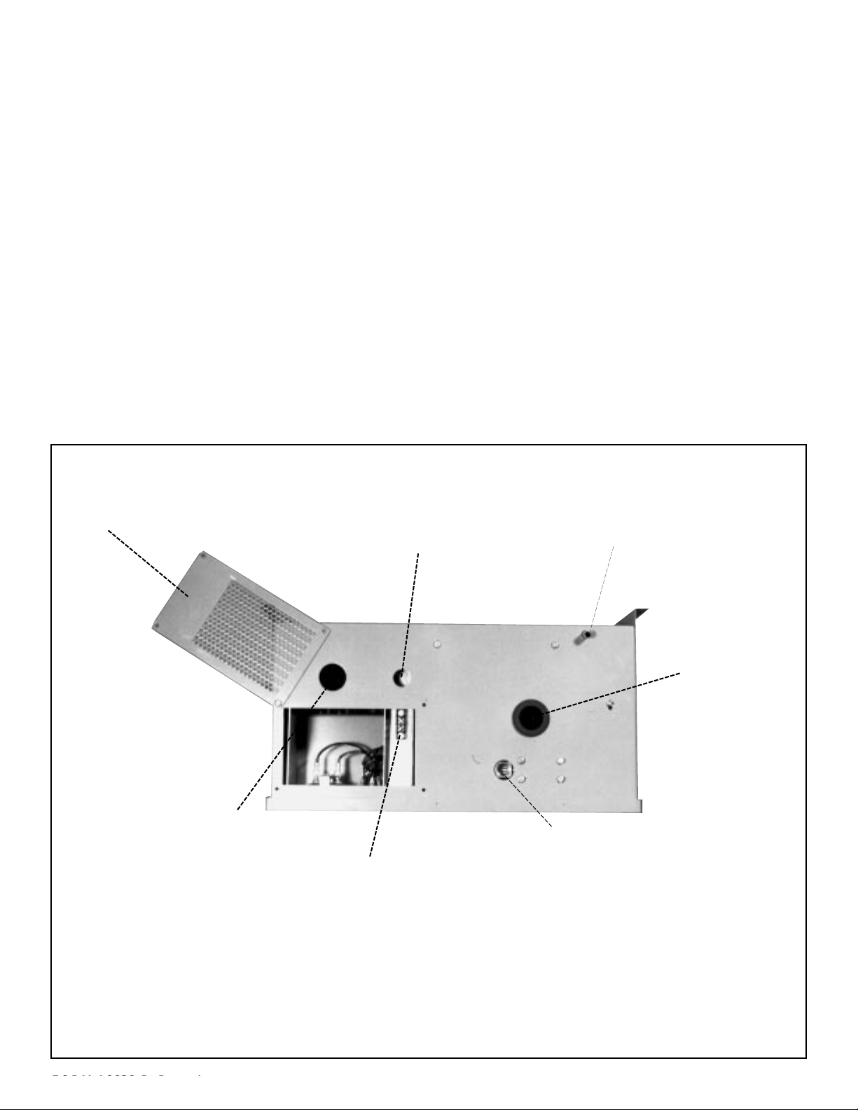
Photo C
Humidistat Terminal Strip Slightly Different
for Models HBGA, HBHA & HBJA
Condensate Return Line
[One for each cylinder]
Humidistat Wiring Opening
Electric Power Wire Opening
Access Panel
Steam Hose
Outlet
(One for each
cylinder)
Humidistat Terminal Strip for Models
HBDA, HBEA & HBFA (Model HBDA Shown)
Water Inlet
Page 5
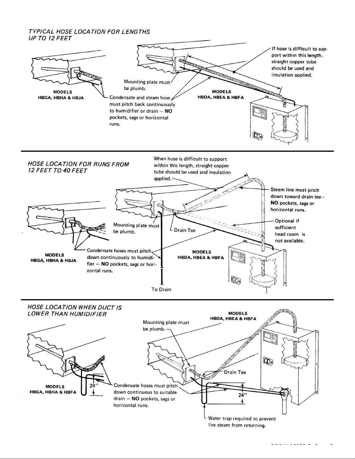
Figure D
Figure E
Figure F
Page 6
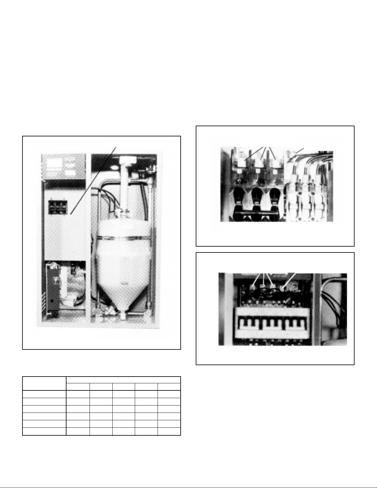
ELECTRICAL CONNECTIONS
POWER MUST BE OFF BEFORE MAKING ANY ELECTRICAL CONNECTIONS
Check unit electrical characteristics on label on outside of
cabinet. It must agree with the power provided to the unit.
If it does not, contact your Carnes Representative.
1.2.Remove screws securing electrical cover panel for
access to wiring (Photo D).
Remove perforated access panel on top of unit
(Photo C).
CONTROL CONNECTIONS
1.
2.
3.
A 7/8” opening is provided on the top of the cabinet. The
control wiring should pass through the opening to the terminal strip (Photo C). Note: A built-in transformer provides 24-volt power for the control circuit. No outside
power supply is required for the control circuit.
When the humidistat completes the circuit between the
humidifier terminal strip, the humidifier will operate. Wire
any auxiliary controls such as high limit humidistat or air
flow switch in series with the humidistat.
Replace perforated access panel.
4.
5.
6.
A fused disconnect or circuit breaker not provided by
Carnes, MUST be installed per local and national
electrical codes. See Table 2 f or recommended circuit
ratings. The magnetic overload switch in the humidifier is NOT for use as a disconnect switch.
An opening is provided on the top of the electrical section (Photo C). Bring electric power wire thru this
opening and connect to electric terminals (Photos E
and F).
Replace electrical cover panel.
3. Connect cabinet ground terminal to an independent
ground (Photos E or F).
DO NOT
use the neutral of
a four-wire power supply.
Electrical Cover Panel
Model HBDA Shown
Photo D
TABLE 2
RECOMMENDED CIRCUIT RATINGS IN AMPERES
VOLTAGE
Model 208 230 460 550 600
HBDA 35 35 20 15 15
HBEA 70 70 35 30 25
HBFA 110 100 50 45 40
HBGA 90 80 40 35 35
HBHA 150 150 70 60 60
HBJA 225 200 100 90 80
Electrical Power Terminals
Ground Terminal
Model HBDA Shown
MODELS WITHOUT SEPARATE TERMINAL BOARD
Photo E
Electrical Power Terminals
Ground Terminal
Model HBFA Shown
MODELS WITH SEPARATE TERMINAL BOARD
Photo F
Page 7
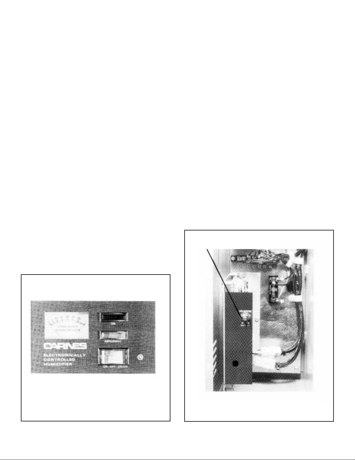
While the external disconnect switch is off, be sure terminal connectors are firmly secured to the top of the cylinder.
1.
2.
3.
4.
5.
6.
7.
8.
9.
Open all water supply valves exter nal to unit.
Turn external disconnect switch to “On” position.
Turn magnetic overload switch(es) to “On” position.
For safety, door interlock disconnects power to cylin-
der(s) when door is open. Humidifier may be operated for service purposes when door is open by pulling
out white button located next to “ON-OFF-DRAIN”
switch. CAUTION: HIGH VOLTAGES ARE PRE-
SENT.
Turn “On-Off-Drain” switch to “On” position. Green
“On” light should now be on.
Unit will now be in operation if humidistat is calling for
humidity. If humidistat is not calling for humidity,
adjust humidistat control upward to check operation.
When humidistat is calling for humidity water will slowly flow into cylinder. Steam output meter will slowly
rise as water enters cylinder.
The “Abnormal” light will remain on until sufficient
water has entered cylinder to provide 50% to 75% of
set output.
NOTE: Unit has been preset at factory for maximum
output as shown by red line on steam output meter.
When full output is reached the fill solenoid valve will
close.
NOTE: When starting unit with new cylinder the
“Abnormal” light may come back on and the drain
solenoid valve and contactor may open for brief periods until water has come to full boil.
10. Humidifier will now cycle ON and OFF in response to
humidistat. Drain solenoid valve will periodically open
to drain small quantity of mineral enriched water from
cylinder.
1.
2.
3.
4.
5.
Drain water from cylinder by turning “On-Off-Drain”
switch to “Drain” position.
Loosen lock nut on steam output control.
Turn steam output rate control fully clockwise.
Turn “On-Off-Drain” switch to “On” position. Steam
output rate will gradually increase as shown on steam
output rate meter. When desired output is reached,
slowly adjust until inlet water valve closes and stops
incoming water.
Tighten lock nut on steam output control.
Models HBDA, HBEA & HBFA Shown
Photo G
ADJUSTING STEAM OUTPUT RATE
Steam output is regulated by adjusting steam output control (Photo H).
To change steam output:
If water boils above line 10 (on cylinder) several hours
after startup of humidifier or installation of new cylinder,
order next lower size model cylinder when replacing. If
water boils below line 3 on Models HBDA, HBEA or HBFA
or below line 0 on Models HBGA, HBHA or HBJA order
one higher size model cylinder when replacing.
Steam Output Control
Photo H
Page 8

1.
2.
3.
For safety, door interlock disconnect power to cylinder(s)
when door is open. Humidifier may be operated when door
is open by pulling out white button located next to “ON-OFFDRAIN” switch. CAUTION: HIGH VOLTAGES ARE PRE-
SENT.
Green “On” light should be on whenever power is supplied
to the humidifier, and “On-Off-Drain” switch is in “On” or
“Drain” position. If green light is not on, check the following
items:
a. Overload switch(es) must be in “On” position.
b. Check glass fuse near circuit board. Replace with prop-
er size as shown on wiring diagram.
c. Check each incoming power wire for proper voltage as
shown on humidifier rating plate. CAUTION: HIGH
VOLTAGES ARE PRESENT.
d. Check green “On” light bulb (24 volt) using voltmeter.
When amber “Abnormal”light is continually on check the fol-
lowing items: (NOTE: Abnormal light will occasionally
be on for short periods during operation such as startup and whenever switch is in “Drain” position).
a. Clean water strainer.
b. All valves in water supply must be open and water pres-
sure above 20 psi.
c. Check drain to be sure water is not constantly draining.
Disassemble and clean drain valve if necessary.
d. Replace cylinder if incoming water is flowing continually
but desired output cannot be reached.
e. Check incoming power wire for proper voltage as shown
on humidifier rating plate. CAUTION: HIGH V OL T A GES
ARE PRESENT.
f. Check voltage at fill solenoid valve. Replace valve is 24
volts are present but valve is not open.
g. Check steam hose for any restriction.
1.
2.
3.
4.
5.
6.
7.
8.
Turn “ON-OFF-DRAIN” switch to “Off.”
Turn magnetic overload switch(es) to “Off”.
Shut off water supply valve ahead of unit.
Remove brass nut by turning counter-clockwise. (A small
amount of water will drain when nut is removed. Use a small
container to catch this water).
Rinse strainer screen to remove deposits.
Replace screen, nut, and gasket in strainer housing.
Turn water supply on — check for leakage.
Turn magnetic overload switch(es) to “On”.
9.
Turn “On-Off-Drain” switch to “On”.
1.
2.
3.
4.
5
6.
7.
8.
9.
10.
11.
12.
13.
14.
Turn “ON-OFF-DRAIN” switch to “Drain”. Completely drain
cylinder.
Turn magnetic overload switch(es) to “Off”.
Slip off cylinder terminal connectors.
Remove steam hose.
Loosen cylinder retaining band.
For Models HBDA, HBEA & HBFA remove cylinder by turn-
ing cylinder counter clockwise. For Models HBGA, HBHA &
HBJA remove cylinder by lifting it from the cylinder holder.
Models HBDA, HBEA & HBFA apply teflon tape or pipe dope
to the threaded portion of new cylinder. Models HBGA,
HBHA & HBJA remove the “O” ring which may have
remained in the holder and clean the “O” ring seat in the
holder.
Models HBDA, HBEA & HBFA screw cylinder into brass
cylinder fitting. Models HBGA, HBHA & HBJA make sure
new “O” ring is on cylinder base and insert cylinder into
holder with enough pressure to seat “O” ring in holder.
Tighten cylinder retaining band.
Replace steam hose and tighten clamp.
Replace terminal connectors on Models HBDA, HBEA &
HBFA in any sequence. On Models HBGA, HBHA & HBJA
match the numbers on the terminal connectors with the
numbers on the cylinders.
Turn magnetic overload switch(es) to “On”.
Turn “On-Off-Drain” switch to “On”.
“Abnormal” light will remain on until water fills cylinder.
MAINTENANCE
NOTE: It is advisable to inspect the humidifier visually at
approximately two week intervals.
CLEANING WATER STRAINER
CHANGING STEAM CYLINDER
NOTE: On two and three cylinder models all cylinders must be
replaced at the same time.
After replacing humidifier cylinder, order a replacement immediately. This will insure having a spare cylinder on hand when the
next change is required.
MISCELLANEOUS
If humidification is not going to be required for a long period of
time, e.g. during summer cooling cycle in a comfort application,
it is recommended the steam cylinders be completely drained
before switching off power and closing water supply valve.
448 South Main Street
P. O. Box 930040
Verona, WI. 53593-004
Phone: 608/845-6411 Fax: 608/845-6470 [email protected] http://www.carnes.com
Copyright © 1998 by Carnes Company
“Due to ongoing research and development CARNES reserves the right to change specifications without notice.”
 Loading...