

Page 1
COPYRIGHT © 2011 CARNES COMPANY
ALL RIGHTS RESERVED
17165, pg 1
SPECIFICATION SHEET
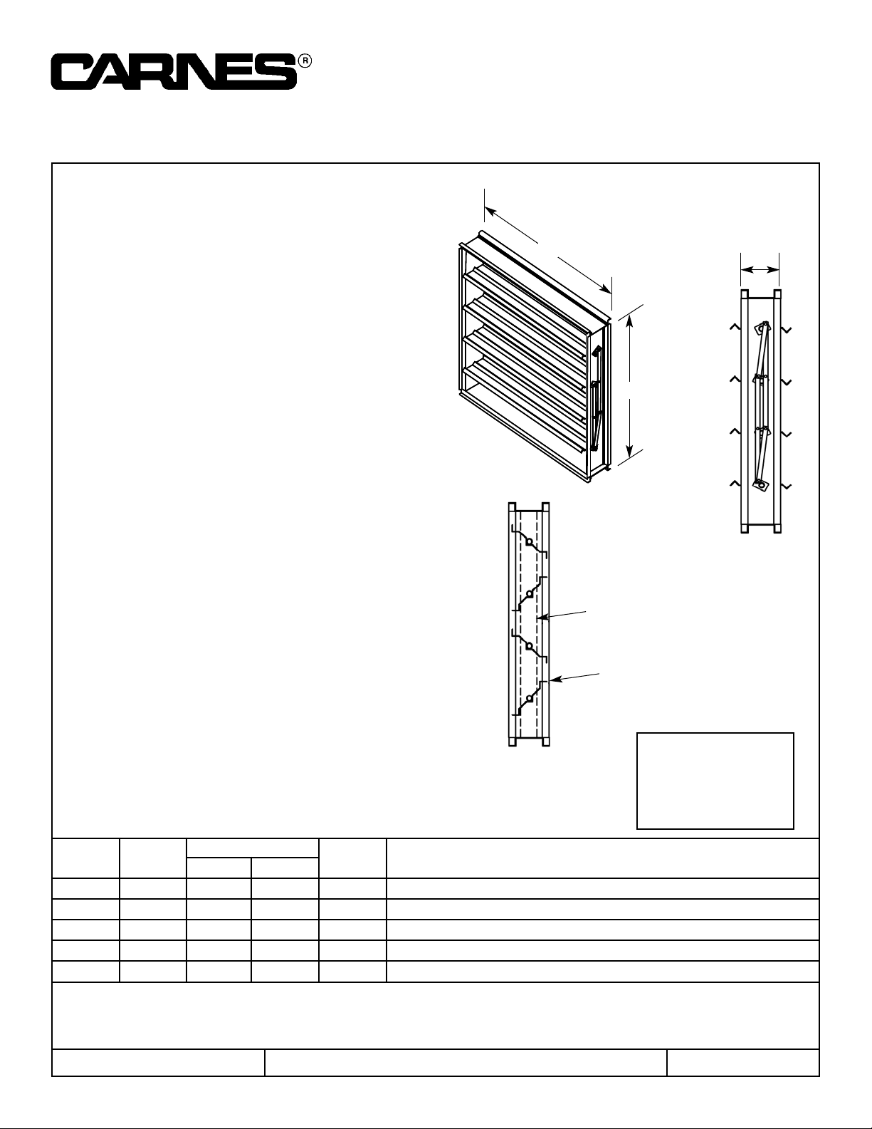
Galvanized 3V Blade Control Damper
Model FNDB - Opposed Blade, Model FDQB - Parallel Blade
CARNES COMPANY, 448 S. Main St., P. O. Box 930040, Verona, WI 53593-0040 Phone: (608)845-6411 Fax: (608)845-6504 [email protected]
Model FDNB & FDQB
Standard Specifications
Frame: roll formed galvanized steel
Blades: 4” - 7” wide, 16 gauge galvanized steel
Bearings: nylon
Linkage: concealed in frame
Axles: 3/8” square plated steel
Control Shaft: Ø1/2” x 4-1/2” long shaft supplied with
all single section dampers for field mounted actuators.
Factory-installed jackshaft supplied with all multiple
section dampers.
Maximum Panel Size: 48”w x 60”h (single section)
Maximum multi-section: unlimited
Minimum Panel Size: 6”w x 6”h
9”h and under - single blade
Options
- Vinyl Blade Seals
- Compression Jamb Seals (stainless steel)
- Header Plates (end flange)
- Hand Quadrant
- Factory Installed Actuators
- Position Switch
- Face and By-pass Damper
- Chain Operator
- Single Flange
- Double Flange
- Bolt Holes in Flange
- Stainless Steel Bushings
- Heresite Coated (air dry)
- Epoxy Coated (powder coated)
- Stand Off Bracket, 2”
Tag Qty.
Size
Frame Variations
Width Height
Project Location
Arch./Engr. Contractor
Representative Date
W
H
5”
Optional
Stainless steel
jamb seals
Vinyl blade seals
12” wide -3500 FPM
24” -2800
36” -2300
48” -2100
FPM Table
Page 2
17165, pg 2
Model FDNB & FDQB Performance Data
Ratings shown are based on tests made in accordance with AMCA standard 500.
Damper
Width x Height
1 in. w.g. Class 4 in. w.g. Class 8 in. w.g. Class
*Torque
(per sq. ft.)
36” x 36” Class III Class III Class III 5.55 lbs-in
Imperial Units (Forward Flow)
*Torque applied to hold damper in closed position.
Damper
Width x Height
1 in. w.g. Class 4 in. w.g. Class 8 in. w.g. Class
*Torque
(per sq. ft.)
36” x 36” Class III Class III Class III 5.55 lbs-in
Imperial Units (Back Flow)
*Torque applied to hold damper in closed position.
Damper
Width x Height
(mm)
250 Pa Class 1 kPa Class 2 kPa Class *Torque
915 x 915 Class III Class III Class III 6,394 grams-cm
Standard International Units (Forward Flow)
*Torque applied to hold damper in closed position.
Damper
Width x Height
(mm)
250 Pa Class 1 kPa Class 2 kPa Class *Torque
915 x 915 Class III Class III Class III 6,394 grams-cm
Standard International Units (Back Flow)
*Torque applied to hold damper in closed position.
Air leakage is based on operation
between 50°F to 104°F. All data
corrected to represent air density
of 0.075 lbs/ft.
3
Air leakage is based on operation
between 10°C to 40°C. All data
corrected to represent air density
of 1.201 kg/m.
3
PL-1
PL-7 PL-X
PL-Y
M
AIRFLOW
AIRFLOW
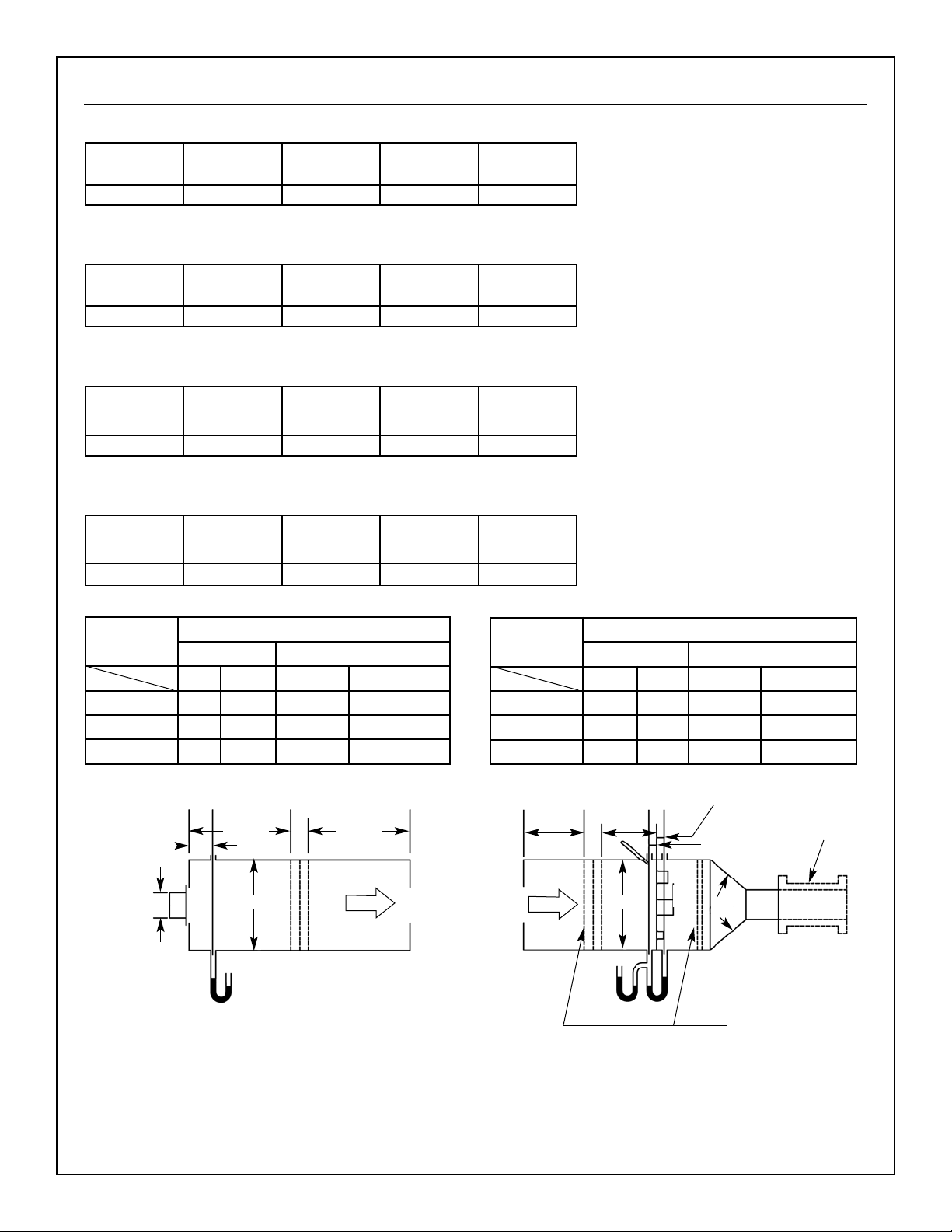
Figure 5.4 - Test Device Setup with Outlet Chamber
Note: For pressure drop testing an outlet
chamber shall have a cross sectional
area at least fifteen times the free
area of the device being tested.
P
s7
W + H
75mm ± 6mm
(3 in. ± .025 in.)
Device
being
tested
M/2 min.
M/2 min.
Figure 6.3 - Airflow Rate Measurement Setup -
Multiple Nozzle Chamber on Fan Inlet
M
M/2 min.
P
s7ΔPn
PL-A
PL-B PL-5 PL-6
Any
angle
Variable
exhaust
system
Settling means
M/2 min.
38mm ± 6mm
(1.5 in. ± .025 in.)
38mm ± 6mm
(1.5 in. ± .025 in.)
t
d5
Leakage, ft.3/min/ft.
2
Required Rating Extended Ranges (optional)
Class
Pressure
1” 4” 8” 12”
I 4 8 11 14
II 10 20 28 35
III 40 80 112 140
All data corrected to represent standard air at a density of 0.075 lbs/ft.
3
Leakage, L/s/m.
3
Required Rating Extended Ranges (optional)
Class
Pressure
0.25 kPa 1.0 kPa 2.0 kPa 3.0 kPa
I 20.3 40.6 55.9 71.1
II 50.8 102 142 178
III 203 406 569 711
D6= Throat dia. of largest nozzle
2.5 D
6
min.
Page 3
17165, pg 3
Model FDNB & FDQB Performance Data
PL-1
PL-2
PL-4
PL-Z
AIRFLOW
AIRFLOW
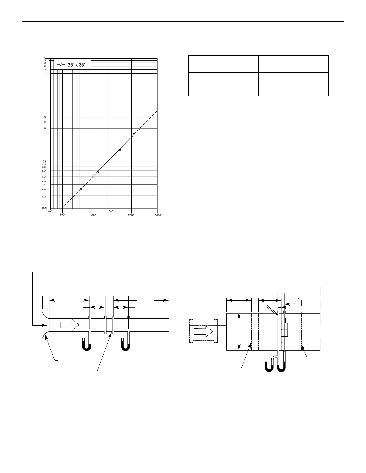
Figure 5.3 - Test Device Setup with Inlet and Outlet Ducts
P
s9
D ± 0.02D
Device being tested
6D min.
Figure 6.5 - Airflow Rate Measurement Setup -
Multiple Nozzle Chamber on Fan Inlet
M
M/5 min.
P
s5ΔPn
PL-A
PL-B
PL-5
PL-6
Variable
exhaust
system
Settling means
M/2 min.
38mm ± 6mm
(1.5 in. ± .025 in.)
38mm ± 6mm
(1.5 in. ± .025 in.)
t
d5
PL-9PL-YPL-X
P
s4
Inlet cone required
if attached to plenum
10D min.
D ± 0.02D
D
6
= Throat dia. of
largest nozzle
Settling means
2.5 D
6
min.
Pressure Drop
Static Pressure Drop (inches w.g.)
FREE AREA VELOCITY (FT/MIN)
Standard air - .075 lbs per cu ft
Ratings do not include the effects of a wire birdscreen
Test based on a 48” x 48” test size, 15 min test duration
Free Area Velocity
ft/min (m/s)
Pressure Drop
in w.g. (Pa)
1000 (5.08) 0.055
1500 (7.62) 0.100
2000 (10.16) 0.175
36 x 36
From supply system and
flow measuring section
 Loading...