

Carnes ARRE Installation Manual
READ AND SAVE THESE INSTRUCTIONS
INSTALLATION and OPERATION MANUAL
VAV RETROFIT
Models ARRE and ARSB
HIGH and LOW VELOCITY UNITS
COPYRIGHT © 2010
All Rights Reserved
18641-F
SUPERSEDES 18641-E
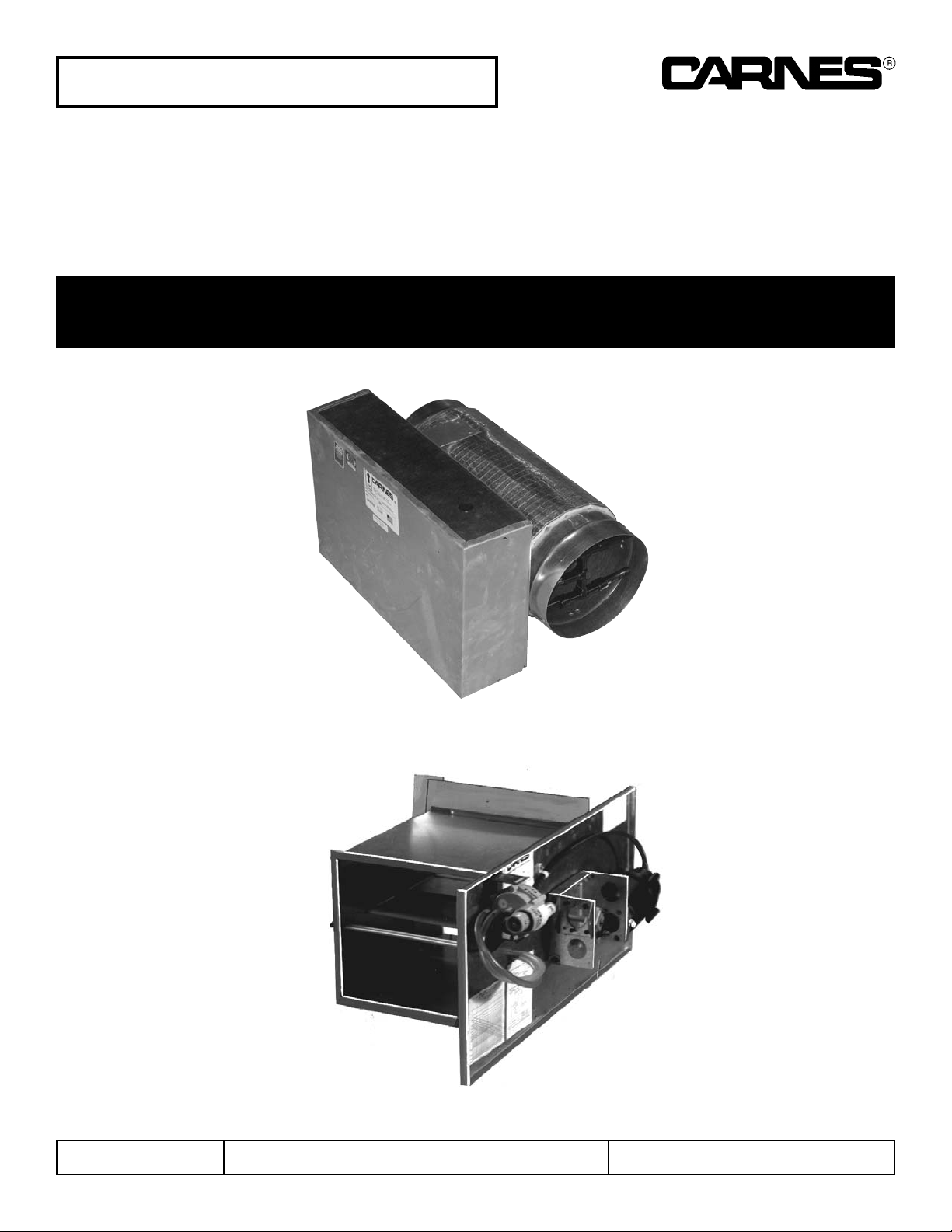
Model ARRE
Model ARSB
CARNES COMPANY 448 S. Main St., P. O. Box 930040, Verona, WI 53593-0040 Phone: (608)845-6411 Fax: (608)845-6470 www.carnes.com
INSPECT UNIT
UNPACKING AND INSPECTION
1. Open shipping carton and check for concealed
ship-ing damage. Report damage immediately to the
carrier that delivered the shipment.
2. Inspect the unit for loose or missing components.
3. Optional accessories may be packed within the unit or
in the same shipping carton
INSTALLATION
GENERAL
1. Each VAV unit and accessory is shipped with an
identification label showing the Carnes order number,
unit item number from the order, unit model number,
maximum and minimum CFM Setting on terminal units
with pressure independent control options, and unit
tagging (or mark).
MODEL ARRE
MOUNTING THE ARRE TERMINAL UNIT
(Round-to-Round)
1. The diameter of the inlet duct in inches must be equal
to the listed size of the ARRE Terminal Unit, e.g., a
duct diameter that measures six (6) inches must be
fitted to a unit Size 06.
2. The control unit must be mounted such that the
velocity sensor is at the inlet of the terminal unit,
upstream of the damper blade.
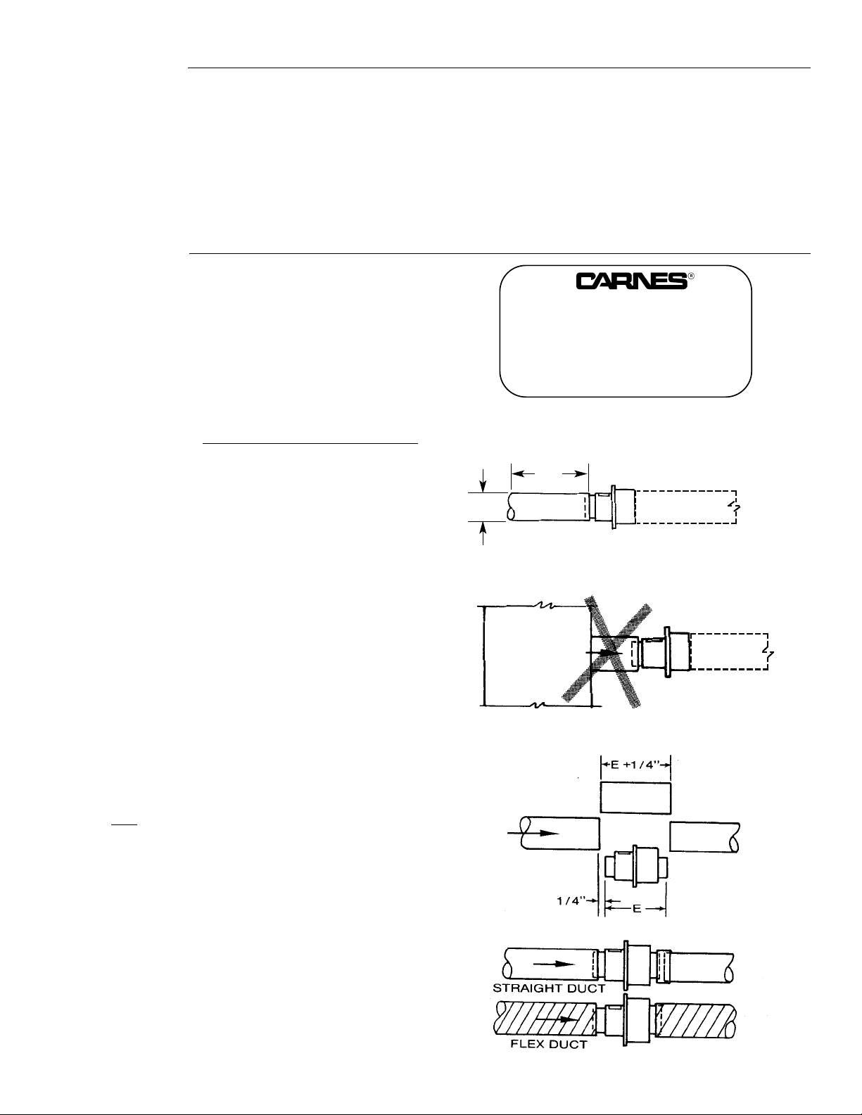
3. It is preferred that the installer attempt to obtain a
minimum of three (3) inlet diameters of straight duct
ahead of the terminal unit inlet to achieve optimum
control accuracy. (Figure 1)
NOTE: Close coupling the terminal unit inlet to the side of
the main duct is not recommended. (Figure 2)
4. Remove the section of duct equal to the length of the
ARRE terminal unit as specified in the Dimensional
Data plus
1/4” for working room. (Figure 3)
5. Facing the ARRE Terminal Unit inlet, mount the
terminal unit in a horizontal level position.
6. Insert the inlet of the ARRE Terminal Unit into the
upstream duct and secure the outlet end to the
downstream duct with a collar (field supplied) or, in the
case of flex duct, with tie bands and duct tape
provided by others, or as prescribed by the job
specifications. (Figure 4).
Figure 2
Figure 3
Figure 4
Figure 1
MAIN DUCT
SUPPLY
3D
MIN
D
STRAIGHT DUCT UPSTREAM
FORM 18641-F, Page 2
CLOSE COUPLING NOT RECOMMENDED
CARNES COMPANY, VERONA, WISCONSIN
ORDER ITEM
MODEL
MAX. CFM / MIN. CFM
MARK
 Loading...