

Page 1
READ AND SAVE THESE INSTRUCTIONS
INSTALLATION and OPERATION MANUAL
PRESSURE VALVE
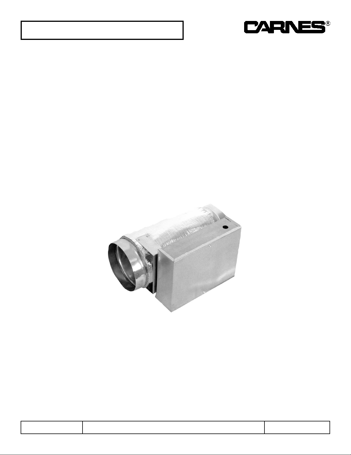
Model AVRA
COPYRIGHT © 2010
All Rights Reserved
18643
Model AVRA
CARNES COMPANY 448 S. Main St., P. O. Box 930040, Verona, WI 53593-0040 Phone: (608)845-6411 Fax: (608)845-6470 www.carnes.com
Page 2
INSPECT UNIT
UNPACKING AND INSPECTION
1. Open shipping carton and check for concealed
shipping damage. Report damage immediately to the
carrier that delivered the shipment.
2. Inspect the unit for loose or missing components.
3. Optional accessories may be packed within the unit or
in the same shipping carton
INSTALLATION
GENERAL
1. Each VAV unit and accessory is shipped with an
identification label showing the Carnes order number,
unit item number from the order, unit model number,
maximum and minimum CFM Setting on terminal units
with pressure independent control options, and unit
tagging (or mark).
MOUNTING THE AVRA TERMINAL UNIT
1. The diameter of the inlet duct in inches must be equal
to the listed size of the AVRA Terminal Unit, e.g., a
duct diameter that measures six (6) inches must be
fitted to a unit Size 06.
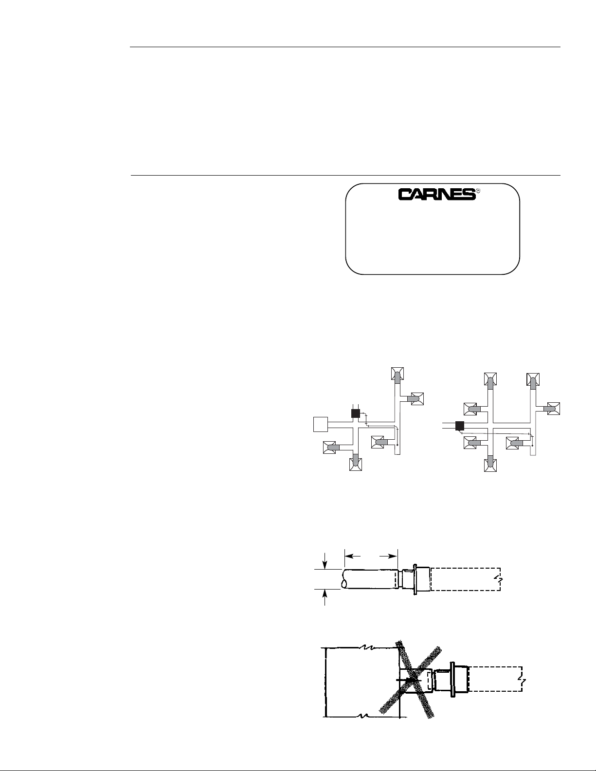
2. It is preferred that the installer attempt to obtain a
minimum of three (3) inlet diameters of straight duct
ahead of the terminal unit inlet. (Figure 2)
NOTE: Close coupling the terminal unit inlet to the side of
the main duct is not recommended. (Figure 3)
Figure 3
Figure 2
MAIN DUCT
SUPPLY
3D
MIN
D
STRAIGHT DUCT UPSTREAM
FORM 18643, Page 2
CLOSE COUPLING NOT RECOMMENDED
CARNES COMPANY, VERONA, WISCONSIN
ORDER ITEM
MODEL
MAX. CFM / MIN. CFM
MARK
PRESSURE VALVE PLACEMENT
1. Determine if the unit will be used as By-pass Pressure
Control or Discharge Pressure Control. By-pass
Pressure Control will open the valve to relieve
excess pressure to a return or plenum. Discharge
Pressure Control will close the valve decreasing
pressure being delivered to downstream air devices.
2. If By-pass Pressure Control is used, mount the unit
off to the side of the main duct as far downstream
from the central fan as possible but still upstream of
any air devices. If Discharge Pressure Control is
used, mount the unit inline with the main duct as far
downstream from the central fan as possible but still
upstream of any air devices. See Figure 1 for a
sample layout.
Figure 1
By-pass Pressure Control
Discharge Pressure Control
Page 3
FORM 18643, Page 3
PITOT TUBE PLACEMENT
1. If By-pass Pressure Control is used, mount the pitot
tube roughly 2/3 down the main duct but on the
upstream side of the pressure valve. If Discharge
Pressure Control is used, mount the pitot tube
roughly 2/3 down the main duct but on the
downstream side of the pressure valve. For best
results, the pitot tube should be at least 7 duct
diameters away from the pressure valve. Again, refer
to Figure 1 for a sample layout.
2. Ten feet of tubing is included with the unit. If
additional tubing is required, it shall be field supplied.
3. Run tubing back to the Pressure Valve and connect
tubing to the High Side of the controller.
CHECKOUT & CALIBRATION OF FACTORY
SUPPLIED ANALOG CONTROLS (ET option)
Checkout
1. The following applies to factory supplied and mounted
controls (ET control option).
2. Regardless of the application, the actuator shall be
mounted Clockwise to CLOSE. Press the clutch
release button on the side of the actuator and rotate
the damper fully Clockwise. If this is not correct,
loosen up allen screws on the actuator and mount the
actuator in a way that the damper shaft is totally
closed when the actuator is fully CW.
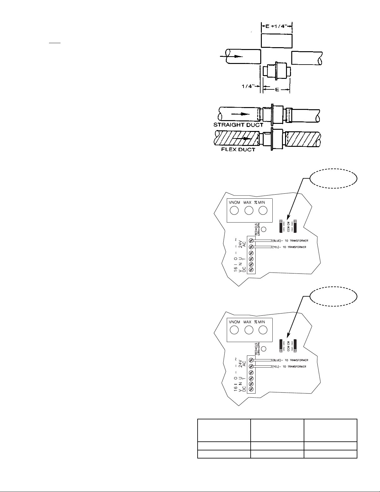
3. Confirm the location of the rotational pins inside the
controller (two pins). For By-pass Pressure Control
units, the two pins shall be on the CCW setting. For
Discharge Pressure Control units, the two pins shall
be on the CW setting. See Figure 6 for proper configuration and Figure 7 for a chart of configurations.
4. If a transformer is supplied with factory controls,
confirm wiring to the controller.
Calibration (make sure to follow the above steps before
attempting to calibrate the unit).
APPLICATION
DAMPER
SHAFT
MOUNTING
ROTATIONAL
PINS (2 Pins)
By-Pass CW to CLOSE CCW
Discharge CW to CLOSE CW
Figure 7
Figure 6
By-pass Pressure
(Pitot tube upstream)
Rotational
Pins to CCW
Discharge Pressure
(Pitot tube downstream)
Rotational
Pins to CW
(2 Pins)
(2 Pins)
3. Remove the section of duct equal to the length of the
AVRA terminal unit as specified in the Dimensional
Data plus
1/4” for working room. (Figure 4)
4. Facing the AVRA Terminal Unit inlet, mount the
terminal unit in a horizontal level position.
5. Insert the inlet of the AVRA Terminal Unit into the
upstream duct and secure the outlet end to the
downstream duct with a collar (field supplied) or, in the
case of flex duct, with tie bands and duct tape
provided by others, or as prescribed by the job
specifications. (Figure 5).
Figure 4
Figure 5
Page 4

FORM 18643, Page 4
CALIBRATION PROCEDURE FOR BY-PASS
PRESSURE CONTROL
1. Remove the cover from the actuator/controller.
2. Confirm the MAX dial is set to 100. This dial will
remain at 100 and never change.
3. The MIN dial should start out at 0 (full CCW).
4. Ensure that the damper begins in a full OPEN
position.
5. “T” into the pressure tubing between the pitot tube and
the controller with a pressure meter (manometer).
6. Turn the MIN dial slowly CW towards 90. At some
point, the damper should start to close and pressure
start to increase. Continue to turn the MIN dial CW
until you reach the desired pressure.
CALIBRATION PROCEDURE FOR
DISCHARGE CONTROL
1. Remove the cover from the actuator/controller.
2. Confirm the MAX dial is set to 100. This dial will
remain at 100 and never change.
3. The MIN dial should start out at 90 (full CW).
4. Ensure that the damper begins in a full OPEN
position.
5. “T” into the pressure tubing between the pitot tube and
the controller with a pressure meter (manometer).
6. Turn the MIN dial slowly CCW towards 0. At some
point, the damper should start to close and pressure
start to decrease. Continue to turn the MIN dial CCW
until you reach the desired pressure.
 Loading...