

Page 1
COPYRIGHT © 2010
SUPERSEDES 18647-L 18647- M, Page 1
All Rights Reserved
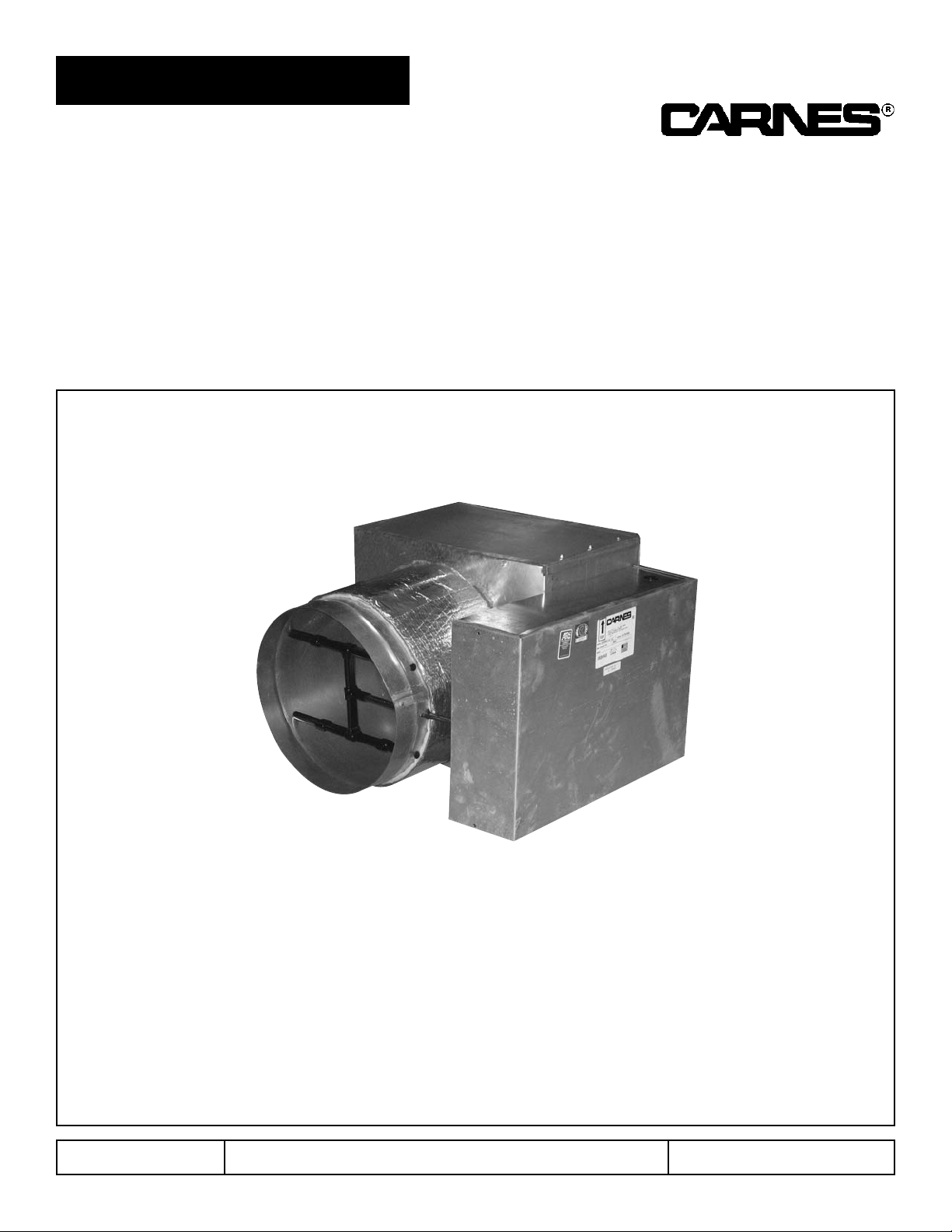
Models AVCD, AVWE, AVED, ABBD, ABWD,
ADCC and ADCD
READ AND SAVE THESE INSTRUCTIONS
INSTALLATION and OPERATION MANUAL
FOR
VAV
THROTTLING UNITS
CARNES COMPANY, 448 S. Main St., P.O.Box 930040, Verona, WI 53593-0040 Phone: 608/845-6411 Fax: 608/845-6470 [email protected] www.carnes.com
Page 2
FORM 18647-M, Page 2
INSPECT UNIT
UNPACKING AND INSPECTION
1. Open shipping carton or crate and check for concealed
shipping damage. Report damage immediately to the carrier
that delivered the unit.
2. Inspect the unit for loose or missing components.
3. Optional accessories may be packed within the unit or in the
same shipping carton.
GENERAL
1. Each VAV unit and accessory is shipped with an
identification label showing the Carnes order number,
unit item number from the order, unit model number,
maximum and minimum CFM settings on terminal
units with pressure independent control options, and
unit tagging (or mark).
INSTALLATION
MOUNTING
1. Units are to be supported in a horizontal and level
position. For convenience, it is suggested that the
units be installed prior to installation of the ceiling tile
grid system.
2. Avoid abrupt transitions or duct turns at the inlet of the
unit that would alter the cross-section area.
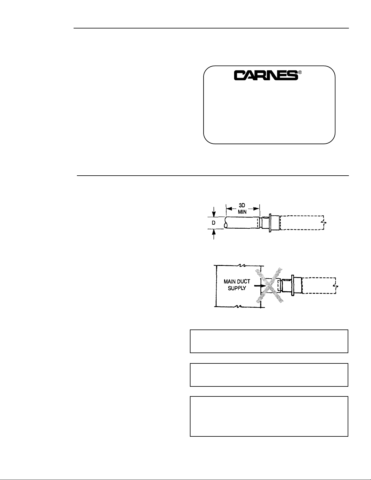
3. A minimum of three duct diameters of straight duct
upstream of inlet sensor is recommended. (i.e., 6” inlet
dia. = 18” or more straight upstream duct.) Figure 1
4. Close coupling the terminal unit inlet to the side of the
main duct is NOT recommended. Figure 2
5. The control unit must be mounted such that the
velocity sensor is at the inlet of the terminal unit,
upstream of the damper blade.
6. Dual duct units may have a velocity sensor mounted
downstream at the discharge opening. The dual duct
unit should be mounted with the two inlets upstream of
the damper blades.
7. The diameter of the inlet duct in inches must be equal
to the listed inlet collar diameter of the terminal unit.
8. A minimum clearance of six inches (6”) is required at
the top discharge opening (by-pass) on Models ABB
and ABW.
9. All control enclosures require adequate clearance to
allow for field adjustments and service.
10. Terminal units may be provided with optional hanger
brackets which are suitable for supporting the terminal
unit by wire hangers or threaded rods.
11. Strap hangers may be used for supporting the units
when hanger brackets are not provided.
CAUTION: Do not install hangers so as to impair the
movement or performance of control
components.
CAUTION: Do not install hangers with screws into
the uninsulated coil casing. Permanent
coil damage may result.
CAUTION: Do not install hangers so as to impair or
restrict the movement of the slide
balancing damper on By-Pass terminal
units. (Models ABB & ABW).
Figure 1
Figure 2
CARNES COMPANY, VERONA, WI
ORDER ITEM
MODEL
MAX. CFM/MIN. CFM
MARK
STRAIGHT DUCT UPSTREAM
CLOSE COUPLING NOT RECOMMENDED
Page 3
FORM 18647-M, Page 3
DUCT CONNECTIONS
1. Units are provided with slip and drive discharge duct
connections.
2. It is suggested that discharge ductwork be lined with
a minimum of 1/2” thick, 1-1/2 lb. density fiberglass
insulation with an erosion resistant surface in
accordance with NFPA 90A (non-residential type air
conditioning and ventilating systems) to provide both
thermal and acoustical insulation.
3. Attenuators are field mounted with slip and drive cleats
provided by others.
4. Sealing of duct work to preclude air leaks should be
done in accordance with the job specifications.
5. It is recommended that flexible ductwork connected to
the inlet be secured using compression band. Rigid
duct should be slipped over the inlet, secured in place
with sheet metal screws, and sealed in accordance
with the job specifications.
BALANCING THE MODELS ABB and ABW
BY-PASS TERMINAL UNITS
I. SYSTEM BALANCING
Prior to setting design flow conditions at each unit the bypass slide dampers must be balanced against downstream
duct resistance.
1. Adjust all thermostats for full cooling so that there is a
maximum air flow to the zone.
2. Using the two air flow pressure taps at each unit, green
(high pressure) and yellow (low pressure), read and
record the air flow pressure to the zone (this value may
be in excess of design flow requirements).
3. After this reading has been taken, adjust the
thermostat for full heat (full by-pass position).
4. When unit is in full by-pass position, adjust the by-pass
slide damper so that the pressure reading is the same
as it was for full cooling to the zone.
5. Continue this procedure at each ABB and ABW unit.
II. SYSTEM DESIGN FLOWS
Once the by-pass slide dampers have been balanced, then
the zone design flow conditions can be set.
1. Again, adjust zone thermostats to full cool (maximum
air flow to the zone).
2. Adjust actuator to the maximum CFM as measured at
the diffusers.
3. Adjust zone thermostat to full heat (minimum air flow to
zone).
4. Adjust actuator to the minimum CFM as measured at
the diffusers.
5. Continue this procedure at each ABB and ABW unit.
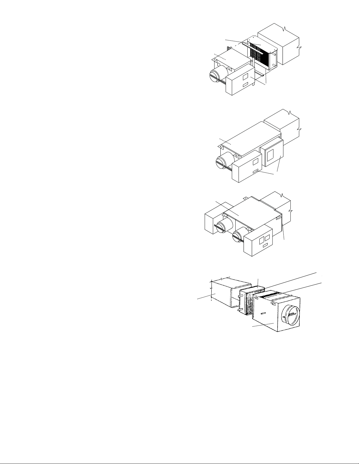
HOT WATER COIL
FIELD or FACTORY
MOUNTED
BASIC UNIT
BASIC UNIT
(Model ABB)
HOT WATER COIL TUBING CONNECTIONS
ARE LOCATED ON CONTROL SIDE OF
TERMINAL UNIT
SINGLE DUCT
DUAL DUCT
BY-PASS
BASIC UNIT
(Model ADC)
ATTENUATOR, RECTANGULAR
DUCT (All Field Mounted)
HOT WATER COIL,
FACTORY MOUNTED
(Model ABW)
6” MINIMUM VERTICAL
CLEARANCE
ATTENUATOR
RECTANGULAR DUCT
(All Field Mounted)
SINGLE DUCT WITH ELECTRIC REHEAT
ATTENUATOR,
RECTANGULAR
DUCT (All Field
Mounted)
ATTENUATOR,
RECTANGULAR
DUCT (All Field Mounted)
BASIC UNIT
ELECTRIC HEATER CONTROL
PANEL IS LOCATED ON CONTROL
SIDE OF TERMINAL UNIT
Page 4
FORM 18647-M, Page 4
COMPANY
448 South Main Street
P. O. Box 930040
Verona, WI 53593-0040
Phone: 608/845-6411
Fax: 608/845-6470
[email protected]
www.carnes.com
HOT WATER COIL CONNECTIONS
ELECTRIC DUCT HEATER CONNECTIONS
ELECTRICAL CONNECTIONS
Hot water coils are factory mounted to the control unit with
coil connections on the same side of the terminal units as
the damper controls.
1. Hot water coil casings are uninsulated. Insulation
requirements must be field applied with material
supplied by others.
2. Water supply valve should be installed on the bottom
coil connection. (Coil shall fill from the bottom.)
Electric duct heaters may be shipped attached or loose
from the terminal unit.
1. When shipped factory mounted to the terminal unit, the
electric heater control panel is on the same side of the
terminal unit as the damper controls.
2. When shipped loose for field mounting, the electric
heater should be mounted as indicated by the “AIRFLOW” arrow and the “UP” arrow on the electric
heater control panel cover.
3. Electric duct heater casings are uninsulated. Insulation
requirements must be field applied with material
supplied by others.
1. Electric duct heater wiring should be done in
accordance with local codes and job specifications.
2. Follow the wiring/piping diagram found on the side of
the unit or the inside of the electric heater control
panel cover.
3. Supply connections must be made using wires rated
for 75°C minimum. DO NOT USE ALUMINUM
CONDUCTORS.
4. If supply connections are for 250 volts or greater, all
wiring must be insulated for 600V.
5. All field and factory made connections should be
checked for tightness before operation.
6. Size wiring conductors for 125% of rated combined
load.
Single Phase KW x 1000
Line Current
=
Voltage
Three Phase KW x 1000
Line Current
=
1.73 x Voltage
7. The following table shows the maximum current for
the supply overcurrent protection device.
Maximum Maximum Overcurrent
Unit Amperage Device Rating
12 15
16 20
20 25
24 30
28 35
32 40
36 45
40 50
48 60
3. Coil tubes are suitable for sweat connections to the
field water pipe system.
4. Hot water coils may be reversed in the field by
removing the slip and drive cleats and rotating the coil
water connections to the other side and reinstalling the
slip and drive cleats.
CAUTION: Plumbing heat sink methods should be used
when soldering near existing joints.
CAUTION: Do not mount electric heaters upside down.
Heater will not function properly and may overheat
causing a serious fire hazard.
CAUTION: Maximum heater discharge temperature
must not exceed 125OF to avoid nuisance tripping.
Discharge Temperature = [(KW x 3160) / CFM] +
Entering Air Temperature.
CAUTION: All sources of supply power must be disconnected before working on this equipment. More
than one disconnect may be required to de-energize
equipment.
 Loading...