

Page 1
READ AND SAVE THESE INSTRUCTIONS
INSTALLATION, OPERATION & MAINTENANCE MANUAL
FOR
Balance and Calibration of
Pneumatic Controls
Models ADCC and ADCD
DUAL DUCT
CARNES COMPANY 448 S. Main St., P. O. Box 930040, Verona, WI 53593-0040 Phone: (608)845-6411 Fax: (608)845-6470 www.carnes.com
COPYRIGHT © 2010 CARNES COMPANY
ALL RIGHTS RESERVED
SUPERSEDES 20225-C 20225-D, Page 1
Page 2
FORM 20225-D, Page 2
Model ADCC - With or Without Airflow Mixing
Model ADCD - Constant Volume Airflow
BALANCE AND CALIBRATION OF MODEL ADCC DUAL DUCT UNITS WITH NO AIRFLOW
MIXING CONTROL.
1. For units that require no HOT or COLD airflow mixing, refer to Installation and Operation Manual for Pressure
Independent Controls - Form 18675.
2. Calibration of these units is the same as setting two Single Duct Throttling Units.
1. Determine the following system parameters:
a. Satisfied set point pressure of the pneumatic thermo
stat (P).
b. Set point temperature of the thermostat (T).
c. Sensitivity output of the thermostat (S).
d. Desired temperature mixing range (M).
2. Calculate the reset start point and reset span for both the
hot and cold deck controllers based on system
parameters.
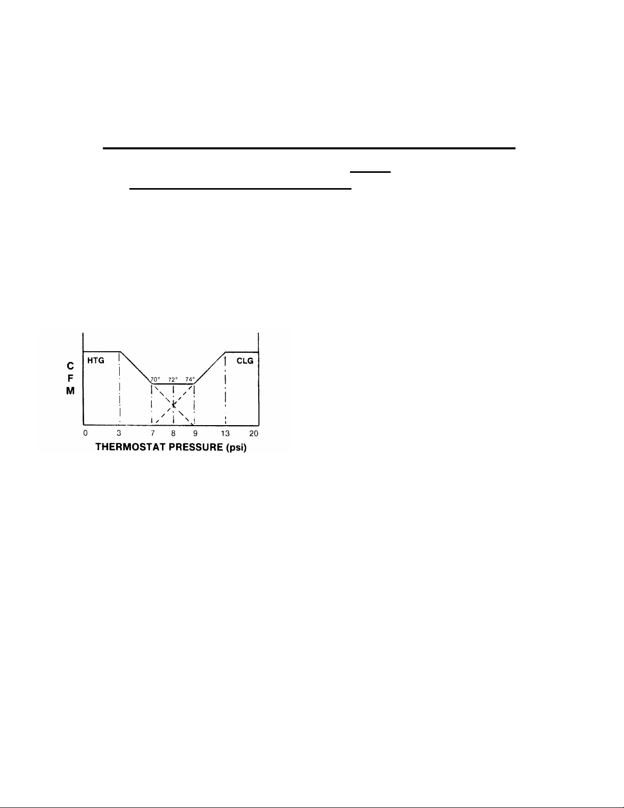
EXAMPLE:
P = 8 psi
T = 72oF
S = 2oF/psi
M = 4oF: (70-74oF)
Based on the desired system parameters the control diagram
can be drawn (see above). Calibration of the reset start point
and reset span can be initiated based on information taken
from the control diagram:
Cold Deck: Reset Start Point = 7 psi
Reset Span = 6 psi
Hot Deck: Reset Start Point = 3 psi
Reset Span = 6 psi
3. Setting the reset start point (if other than 8 psi):
a. Remove the cap on the “G” port of the controller and
connect an accurate 0-30 psi (max.) gauge.
b. Regulate the thermostat pressure to the “T” port of the roller
to the desired start point pressure.
c. Adjust the “Reset Start” on the controller to indicate 0 psi on
the “G” port gauge. Then adjust the “RESET Start” to indicate a pressure slightly higher than 0 psi (i.e. 0.1 psi) to
ensure that this setting is not over-adjusted.
d. Remove the auxiliary gauge from the “G” port and replace
the cap over the “G” port tap.
4. Adjusting the reset span (if other than 5 psi).
a. Remove the cap on the “G” port of the controller and
connect an accurate 0-30 (max.) gauge.
b. Regulate the thermostat pressure to the “T” port of the
controller to 20 psi.
c. Adjust the “Reset Span” on the controller to indicate the
desired span on the “G” port gauge.
d. Remove the auxiliary gauge from the “G” port and replace
the cap over the “G” port tap.
5. Calibration Procedures: Setting maximum and minimum
CFM.
a. Direct Acting Thermostat -- Cold Deck
1. Set zone thermostat call for full heating (0 psi) at the “T”
port of controller.
2. Connect a differential pressure gauge across the
Cold Deck inlet sensor tubes. The green tube is the
total pressure (“HI” signal) and the yellow tube is the
static pressure (“LO” signal).
3. Adjust the “LO stat DP” to the desired minimum cooling
airflow limit. REFER TO CALIBRATION CHART ON
INLET.
4. Set zone thermostat to call for full cooling (20 psi) at the
“T” port of controller.
5. Adjust the “HI stat DP” to the desired maximum cooling
airflow limit. REFER TO CALIBRATION CHART ON
INLET.
b. Direct Acting Thermostat -- Hot Deck
1. Set zone thermostat to call for full heating (0 psi) at the
“T” port of controller.
2. Connect a differential pressure gauge across the Hot
Deck inlet sensor tubes. The green tube is the total
pressure (“HI” signal) and the yellow tube is the static
pressure (“LO” signal).
3. Adjust the “LO stat DP” to the desired maximum cool-
ing airflow limit. REFER TO CALIBRATION CHART ON
INLET.
4. Set zone thermostat to call for full cooling (20 psi) at the
“T” port of controller.
5. Adjust the “HI stat DP” to the desired minimum cooling
airflow limit. REFER TO CALIBRATION CHART ON
INLET.
c. Reverse Acting Thermostat -- Cold Deck
1. Set zone thermostat to call for full cooling (0 psi) at the
“T” port of controller.
2. Connect a differential pressure gauge across the Cold
Deck inlet sensor tubes. The green tube is the total
pressure (“HI” signal) and the yellow tube is the static
pressure (“LO” signal).
3. Adjust the “LO stat DP” to the desired maximum cool-
ing airflow limit. REFER TO CALIBRATION CHART ON
INLET.
4. Set zone thermostat to call for full heating (20 psi) at the
“T” port of controller.
5. Adjust the “HI stat DP” to the desired minimum cooling
airflow limit. REFER TO CALIBRATION CHART ON
INLET.
d. Reverse Acting Thermostat -- Hot Deck
1. Set zone thermostat to call for full cooling (0 psi) at the
“T” port of controller.
2. Connect a differential pressure gauge across the Hot
Deck inlet sensor tubes. The green tube is the total
pressure (“HI” signal) and the yellow tube is the static
pressure (“LO” signal).
3. Adjust the “LO stat DP” to the desired minimum heating
airflow limit. REFER TO CALIBRATION CHART ON
INLET.
4. Set zone thermostat to call for full cooling (20 psi) at the
“T” port of controller.
5. Adjust the “HI stat DP” to the desired maximum heating
airflow limit. REFER TO CALIBRATION CHART ON
INLET.
BALANCE AND CALIBRATION OF MODEL ADCC DUAL DUCT UNITS WITH
ADJUSTABLE AIRFLOW MIXING
CONTROL OPTIONS
Page 3

FORM 20225-D, Page 3
NOTES:
1. Allow 3-4 minutes between “HI” and “LO” limit adjustments for
controller and damper to stabilize.
2. “LO” stat DP adjustment will affect the “HI” stat DP setting. The
“LO” stat DP adjustment must be adjusted first or the “HI” stat
DP will require readjustment.
3. Reset start point and reset span must be adjusted (if necessary)
before calibrating the max. and min. of the controller.
(Adjustment of the reset span will effect the “HI” stat DP”
setting).
4. Deviation from the factory set 5 psi reset span will effect the
differential pressure range of 1.0” w.g.
BALANCE AND CALIBRATION OF MODEL ADCD DUAL DUCT UNITS WITH
CONSTANT VOLUME CONTROL OPTIONS
NOTES:
1. Set the zone thermostat to call for full cooling.
2. Remove caps from the tees in the sensor tubing near the unit discharge.
3. Connect a differential pressure gauge across the discharge sensor tubing. The green tube (or black with green stripe) is the
total pressure (“HI” signal) and the yellow tube (or black with yellow stripe) is the static pressure (“LO” signal).
4. Wait 3-4 minutes and the visually verify that the hot deck damper is closed. (Slot on the hot deck damper shaft should be vertical). If
the hot deck damper is not closed, decrease the “LO Adj” knob on the hot deck multi-function controller as necessary to close just the
damper - DO NOT OVER ADJUST.
5. Read the differential pressure signal across the discharge sensor and verify that the cold deck airflow is equal to the recommended
constant volume design CFM. Reference the airflow calibration chart on the unit discharge for delta P versus CFM values. If the CFM
is not equal to design flow - adjust the “HI” limit on the cold deck controller to obtain the desired flow.
6. Set the zone thermostat to call for full heating.
7. Wait 3-4 minutes and the visually verify that the cold deck damper is closed. (Slot on the cold deck damper shaft should be vertical).
If the cold deck damper is not closed, decrease the “LO” limit on the cold deck controller as necessary to close just the damper - DO
NOT OVER ADJUST.
8. Read the differential pressure signal across the discharge sensor and verify that the hot deck airflow is equal to the recommended
constant volume design CFM. Reference the airflow calibration chart at the discharge of the unit for delta P versus CFM values. If
the CFM is not equal to design flow - adjust the “LO adj” dial on the hot deck controller to obtain the desired flow.
9. Set the zone thermostat to call for full cooling.
10. Wait 3-4 minutes and verify that the unit controls back to full cooling.
11. Read the differential pressure signal across the discharge sensor and fine tune the flow adjustments if necessary.
12. Set the zone thermostat to full heating.
13. Wait 3-4 minutes, verify that the unit controls back to full heating and fine tune adjustments if necessary.
14. Set zone temperature to desired room temperature.
15. Remove the differential pressure gauge from the discharge flow sensor.
16. Replace the caps on the tees in the discharge sensor tubing.
NOTES:
1. Set the zone thermostat to call for full cooling.
2. The cold deck damper can go to the full open position and still not satisfy the space cooling requirements when there is insufficient
cooling air in the unit. The discharge sensor on the dual duct unit may then start to open the hot deck damper to satisfy the total air
volume requirement. This causes additional hot air to enter the space causing under cooling.
3. To obtain optimum performance throughout the control range of the unit the hot deck CFM should be set approximately 5% lower than
the cold deck CFM.
EXAMPLE: Design Flow = 400 CFM
Cold Deck Setting = 410 CFM
Hot Deck Setting = 390 CFM
4. An excessive difference of inlet static pressure between the hot and cold deck may cause less than optimum control performance.
 Loading...