

Page 1

KODAK 9000 3D Extraoral Imaging System
Installation Guide
Page 2

Notice
Congratulations on your purchase of the KODAK 9000 3D Extraoral Imaging System. Thank you for your confidence
in our products and we will do all in our power to ensure your complete satisfaction.
The Installation Guide for the KODAK 9000 3D Extraoral Imaging System includes information both on the
Panoramic features as well as the 3D features. If you have purchase only the KODAK 9000 Panoramic system,
information relevant to 3D does not apply to yo ur radiol og ical syst em. We recommend that you thoroughly familiarize
yourself with this Guide in order to make the most effective use of your system.
The information contained in this Guide may be subject to modification without notice, justification or notification to
the persons concerned.
No part of this Guide may be reproduced without the express permission of Carestream Health, Inc.
This document is originally written in English.
Manual Name: KODAK 9000 3D Extraoral Imaging System Installation Guide
Part Number: SM711
Revision Number: Edition 01
Print Date: 12/2007
The brand names and logos reproduced in this Guide are copyright.
KODAK is a trademark of KODAK used under License.
KODAK 9000 3D Extraoral Imaging System, complies with Directive 93/42/CEE relating to medical equipment.
0086
Page 3

Contents
1—About This Guide
Conventions in this Guide. . . . . . . . . . . . . . . . . . . . . . . . . . . . . . . . . . . . . . . . . . . . . . . . . . . . . . . . . . . . . . . . . . . . . . .1–1
Note to the User. . . . . . . . . . . . . . . . . . . . . . . . . . . . . . . . . . . . . . . . . . . . . . . . . . . . . . . . . . . . . . . . . . . . . . . . . . . . . . .1–2
Warning and Safety Instructions . . . . . . . . . . . . . . . . . . . . . . . . . . . . . . . . . . . . . . . . . . . . . . . . . . . . . . . . . . . . . . . . . .1–2
Marking and Labeling Symbols . . . . . . . . . . . . . . . . . . . . . . . . . . . . . . . . . . . . . . . . . . . . . . . . . . . . . . . . . . . . . . . . . .1–4
Responsibility and Warranty . . . . . . . . . . . . . . . . . . . . . . . . . . . . . . . . . . . . . . . . . . . . . . . . . . . . . . . . . . . . . . . . . . . . .1–5
2—KODAK 9000 3D DIGITAL IMAGING UNIT OVERVIEW
Functional Overview. . . . . . . . . . . . . . . . . . . . . . . . . . . . . . . . . . . . . . . . . . . . . . . . . . . . . . . . . . . . . . . . . . . . . . . . . . .2–1
Control Panel Overview . . . . . . . . . . . . . . . . . . . . . . . . . . . . . . . . . . . . . . . . . . . . . . . . . . . . . . . . . . . . . . . . . . . . . . . .2–4
X-Ray Remote Control Overview. . . . . . . . . . . . . . . . . . . . . . . . . . . . . . . . . . . . . . . . . . . . . . . . . . . . . . . . . . . . . . . . .2–5
3—KODAK 9000 3D PACKAGING
Standard Packaging. . . . . . . . . . . . . . . . . . . . . . . . . . . . . . . . . . . . . . . . . . . . . . . . . . . . . . . . . . . . . . . . . . . . . . . . . . . .3–1
Head Assembly . . . . . . . . . . . . . . . . . . . . . . . . . . . . . . . . . . . . . . . . . . . . . . . . . . . . . . . . . . . . . . . . . . . . . . . . . . . . . . .3–2
Box (A) Components . . . . . . . . . . . . . . . . . . . . . . . . . . . . . . . . . . . . . . . . . . . . . . . . . . . . . . . . . . . . . . . . . . . . . . .3–2
Box (B) Components . . . . . . . . . . . . . . . . . . . . . . . . . . . . . . . . . . . . . . . . . . . . . . . . . . . . . . . . . . . . . . . . . . . . . . .3–3
Column Assembly. . . . . . . . . . . . . . . . . . . . . . . . . . . . . . . . . . . . . . . . . . . . . . . . . . . . . . . . . . . . . . . . . . . . . . . . . . . . .3–5
4—SITE PREPARATION BEFORE INSTALLATION
Standard Compliance . . . . . . . . . . . . . . . . . . . . . . . . . . . . . . . . . . . . . . . . . . . . . . . . . . . . . . . . . . . . . . . . . . . . . . . . . .4–1
Environmental Requirements . . . . . . . . . . . . . . . . . . . . . . . . . . . . . . . . . . . . . . . . . . . . . . . . . . . . . . . . . . . . . . . . . . . .4–1
Unit Dimensions . . . . . . . . . . . . . . . . . . . . . . . . . . . . . . . . . . . . . . . . . . . . . . . . . . . . . . . . . . . . . . . . . . . . . . . . . . . . . .4–2
Electrical Requirements . . . . . . . . . . . . . . . . . . . . . . . . . . . . . . . . . . . . . . . . . . . . . . . . . . . . . . . . . . . . . . . . . . . . . . . .4–3
X-Ray Room Requirement . . . . . . . . . . . . . . . . . . . . . . . . . . . . . . . . . . . . . . . . . . . . . . . . . . . . . . . . . . . . . . . . . . . . . .4–7
PC System Requirements . . . . . . . . . . . . . . . . . . . . . . . . . . . . . . . . . . . . . . . . . . . . . . . . . . . . . . . . . . . . . . . . . . . . . . .4–9
5—INSTALLING THE KODAK DENTAL IMAGING SOFTWARE
6—INSTALLING THE UNIT
Tool Requirements . . . . . . . . . . . . . . . . . . . . . . . . . . . . . . . . . . . . . . . . . . . . . . . . . . . . . . . . . . . . . . . . . . . . . . . . . . . .6–1
Technical Staff Requirements . . . . . . . . . . . . . . . . . . . . . . . . . . . . . . . . . . . . . . . . . . . . . . . . . . . . . . . . . . . . . . . . . . . .6–1
Opening the Boxes . . . . . . . . . . . . . . . . . . . . . . . . . . . . . . . . . . . . . . . . . . . . . . . . . . . . . . . . . . . . . . . . . . . . . . . . . . . .6–2
Installing the Unit . . . . . . . . . . . . . . . . . . . . . . . . . . . . . . . . . . . . . . . . . . . . . . . . . . . . . . . . . . . . . . . . . . . . . . . . . . . . .6–4
Installing the Column . . . . . . . . . . . . . . . . . . . . . . . . . . . . . . . . . . . . . . . . . . . . . . . . . . . . . . . . . . . . . . . . . . . . . . .6–4
Installing the Head . . . . . . . . . . . . . . . . . . . . . . . . . . . . . . . . . . . . . . . . . . . . . . . . . . . . . . . . . . . . . . . . . . . . . . . . .6–6
Installing the Fixed Arm. . . . . . . . . . . . . . . . . . . . . . . . . . . . . . . . . . . . . . . . . . . . . . . . . . . . . . . . . . . . . . . . . . . . .6–8
Connecting the General Wiring . . . . . . . . . . . . . . . . . . . . . . . . . . . . . . . . . . . . . . . . . . . . . . . . . . . . . . . . . . . . . . .6–9
Fitting the Covers . . . . . . . . . . . . . . . . . . . . . . . . . . . . . . . . . . . . . . . . . . . . . . . . . . . . . . . . . . . . . . . . . . . . . . . . . . . .6–11
7—Maintenance
Annual Maintenance . . . . . . . . . . . . . . . . . . . . . . . . . . . . . . . . . . . . . . . . . . . . . . . . . . . . . . . . . . . . . . . . . . . . . . . . . . .7–1
KODAK 9000 3D Extraoral Imaging System_Installation Guide (SM711)_Ed 01 iii
Page 4

Contents
8—TECHNICAL SPECIFICATIONS
Compliance with International Standards . . . . . . . . . . . . . . . . . . . . . . . . . . . . . . . . . . . . . . . . . . . . . . . . . . . . . . . . . . .8–1
Unit Technical Specifications . . . . . . . . . . . . . . . . . . . . . . . . . . . . . . . . . . . . . . . . . . . . . . . . . . . . . . . . . . . . . . . . . . . .8–2
Unit Electronic Specifications . . . . . . . . . . . . . . . . . . . . . . . . . . . . . . . . . . . . . . . . . . . . . . . . . . . . . . . . . . . . . . . . . . .8–4
X-Ray Generator Technical Specifications . . . . . . . . . . . . . . . . . . . . . . . . . . . . . . . . . . . . . . . . . . . . . . . . . . . . . . . . .8–5
iv
Page 5
Chapter 1
About This Guide
Conventions in this Guide
The following special messages emphasize information or indicate potential risk to persons or
equipment:
WARNING
Warns you to avoid injury to yourself or others by following the
safety instructions precisely.
CAUTION
Alerts you to a condition that might cause serious damage.
IMPORTANT
Alerts you to a condition that might cause problems.
NOTE
Emphasizes important information.
TIP
Provides extra information and hints.
KODAK 9000 3D Extraoral Imaging System_Installation Guide (SM711)_Ed 01 1–1
Page 6
Note to the User
Note to the User
WARNING
X-rays can be harmful and dangerous if not used properly. The
instructions and warnings contained in this guide must be therefore
carefully followed.
As a manufacturer of radiology units that conform to stringent radiological protection
standards in force throughout the world, we guarantee a maximum degree of protection against
radiation hazards. Nonetheless, you are handling a radiology unit specially designed to emit
x-ray doses in order to carry out a medical diagnosis.
The room in which your radiology Unit is to be installed must comply with all official
regulations applicable to protection against radiatio n. You must install your radiology unit in a
room protected against x-ray emission. This room must reduce the frequency interferences of
the 30MHz to 1GHz band to at least 12db.
Your local representative will assist you in the initial use of your radiology Unit and will
supply any relevant information you may require.
T o use and operate your pano ramic unit and your digital imaging software you must follow the
instructions contained in this guide.
Warning and Safety Instructions
When operating the Kodak 9000 unit, observe the following warning and safety instructions:
DANGER OF ELECTRIC SHOCK
This is an electrical Unit. DO NOT expose it to water spray. Such action
may cause an electric shock or a malfunction of the Unit.
LASER WARNING
For maximum safety, advise the patient not to look at the beam.
Before turning on the beams, lower the Frankfurt plane beam to
LASER RADIATION
DO NOT STARE INTO BEAM
CLASS 2 LASER PRODUCT
Maximum laser output:1mW,650nm
IEC60825-1:1993+A1:1997+A2:2001
the lowest level. While making adjustments, ensure that the beam
is not directed into the patient's eyes.
1–2 About This Guide
Page 7

Warning and Safety Instructions
WARNINGS:
• You are responsible for the operation and maintenance of this unit. Only legally
qualified persons can operate this unit. DO NOT open the cover of the unit.When
necessary, have a trained authorized service technician carry out inspection and
maintenance operations.
• Install this Unit in an x-ray room that complies with current installation
standards. From this location, you must be able to maintain visual or audio
communication with the patient and be able to access the Acquisition interface
module during exposure. This Unit must be permanently connected to the
ground with a fixed power supply cable.
• DO NOT place the PC and the peripheral equipment connected to it in the
immediate vicinity of the patient in the Unit. Leave at least 1.5 m distance
between the patient and the Unit. The PC and the peripheral equipment must
conform to the IEC60950 standard.
• See your computer installation guide for details of the data processing system,
PC and screen. Leave a sufficient amount of clear space around the CPU to
ensure that it is properly ventilated.
• To obtain maximum image quality and visual comfort, position the screen to
avoid direct light reflections from internal or external lighting.
• DO NOT operate the Unit if there is the threat of an earthquake. Following an
earthquake, ensure that the Unit is operating satisfactorily before using it again.
Failure to observe this precaution may expose patients to hazards.
• X-ray equipment is hazardous to patients and the operator if you do not observe
the exposure safety factors and operating instructions.
• DO NOT place objects within the field of operation of the Unit.
• The patient should wear a protective lead-lined shoulder apron, unless other
Radiation Protection Protocols apply locally.
• Disinfect any parts of the Unit that come into contact with the patient and the
operator after each patient has been exposed to x-rays.
• While adjusting the height of the Unit, ensure that the patient is kept clear of the
mechanism.
• When the Unit is not in use, ensure that the ON/OFF switch is set to OFF (O).
• If the Unit develops a fault, switch it to off (O), display an “Unserviceable” notice
and contact a service technician.
• To dispose of the Unit or its components, contact a service technician.
• Ask the patient to refrain from moving during the entire period of exposure.
• Ask the patient to remain still until the Unit arm has stopped moving and the
RESET movement has completed.
• DO NOT use this Unit in conjunction with oxygen-rich environments. This Unit
is not intended for use with flammable anesthetics or flammable agents.
KODAK 9000 3D Extraoral Imaging System_Installation Guide (SM711)_Ed 01 1–3
Page 8
Marking and Labeling Symbols
Marking and Labeling Symbols
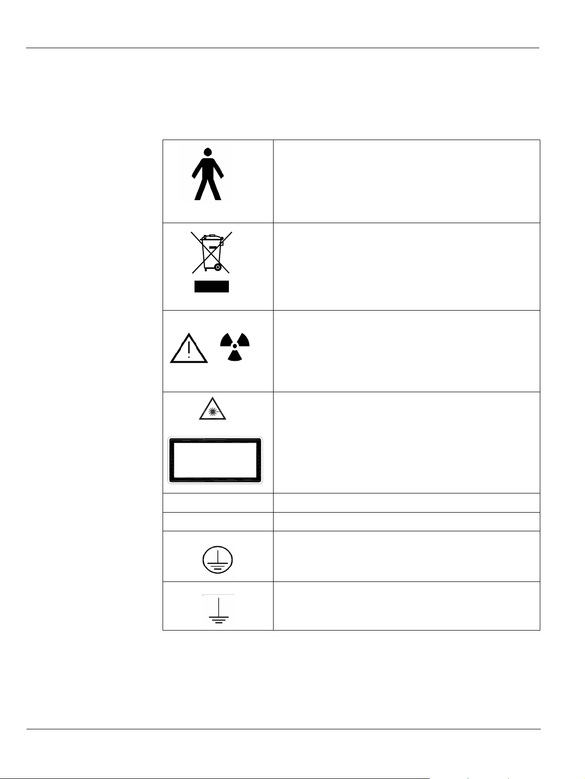
Type B device symbol complying with the IEC 60601-1
standard
In the EEC, this symbol indicates: DO NOT discard this
product in a trash receptacle; use an appropriate recovery
and recycling facility .
Contact your local sales representative for additional
information on the collection and recovery programs
available for this product
WARNING and IONIZING RADIATION symbols warn
you about radiation dangers.
LASER RADIATION
DO NOT STARE INTO BEAM
CLASS 2 LASER PRODUCT
Maximum laser output:1mW,650nm
IEC60825-1:1993+A1:1997+A2:2001
N Connecting point to the neutral conductor
L Connecting point to the live conductor
LASER WARNING
Laser radiation. DO NOT stare into the beam.
Class 2 laser product.
Maximum output power: 1mW, 650 nm (IEC 60825-1
standard)
This Unit emits laser radiation.
Protection ground (G)
Functional ground
1–4 About This Guide
Page 9

Responsibility and Warranty
Only damage affecting products themselves will be considered. The client can in no case claim
damage compensation if it does not purely concern the product itself and provided that this
exclusion of responsibility does not infringe any legal measures.
This warranty does not cover damages and faults due to accident, incorrect usage, improper
use, negligence, or wear and tear due to normal use.
Carestream Health, Inc. can not be held liable for the consequences resulting from the
non-application of the instructions contained in the installation and user manuals, name ly
bodily harm, profit loss, operational interruptions, data loss, loss of a financial nature, or any
direct or indirect damage.
Carestream Health, Inc. reserves the right to examine any presumed defect.
Clients are not entitled to delay the payment of their bills or any financial deductions by way
of products reputed to be faulty.
Due to the continuous development of its products, Carestream Health, Inc. reserves the right
to amend at any time the manual and products mentioned therein, without justification or
notification to the people involved.
Responsibility and Warranty
Our products are guaranteed in their original packaging. Carestream Health, Inc. cannot be
held liable for damages resulting from transportation.
Consumable spares, software and accessories are excluded from the warranty.
KODAK 9000 3D Extraoral Imaging System_Installation Guide (SM711)_Ed 01 1–5
Page 10

Responsibility and Warranty
1–6 About This Guide
Page 11
Chapter 2
KODAK 9000 3D DIGITAL IMAGING UNIT OVERVIEW
The KODAK 9000 3D digital imaging unit is compliant with the requirements of the EEC and
international medical standards.
The KODAK 9000 3D Unit has been designed to carry out the following radiological
examinations:
• Panoramic
• Maxillary Sinus
• Temporomandibular Joints (TMJ)
• 3D images
The KODAK 9000 3D Unit is composed of the following functional components:
• Control Panel
• Remote Control
Functional Overview
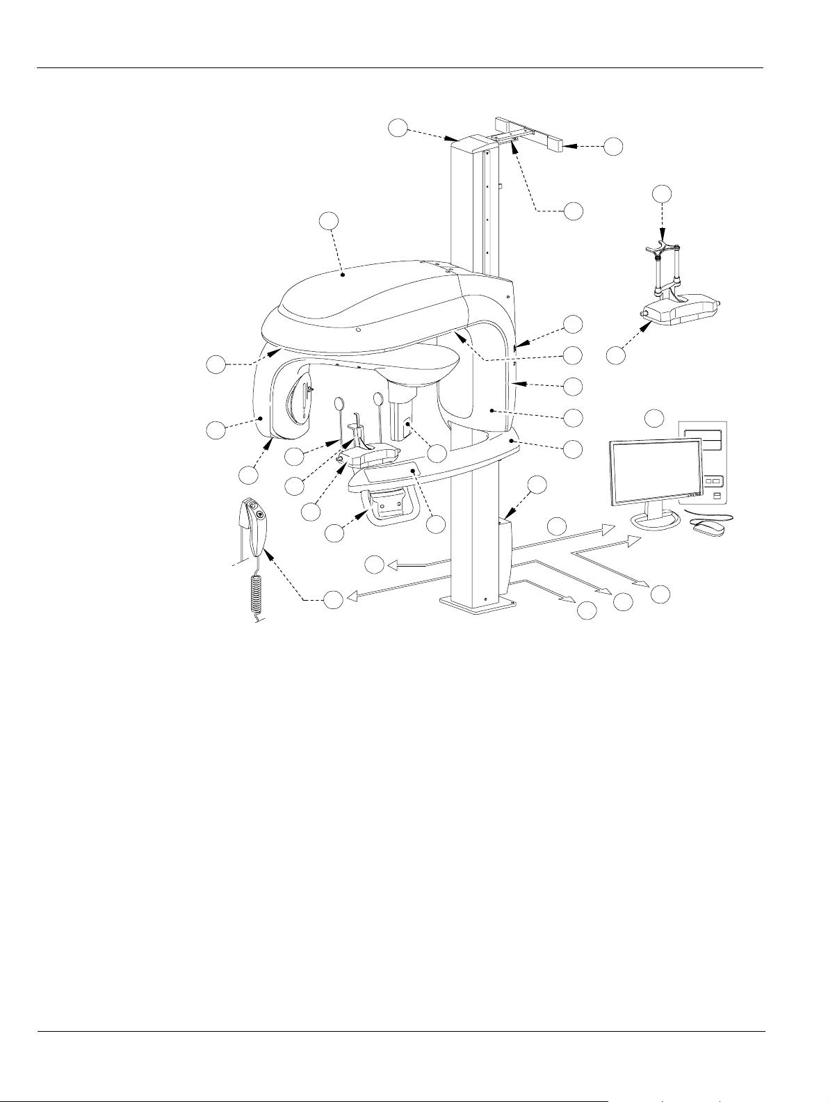
The following figures illustrate the components of the KODAK 9000 3D Unit.
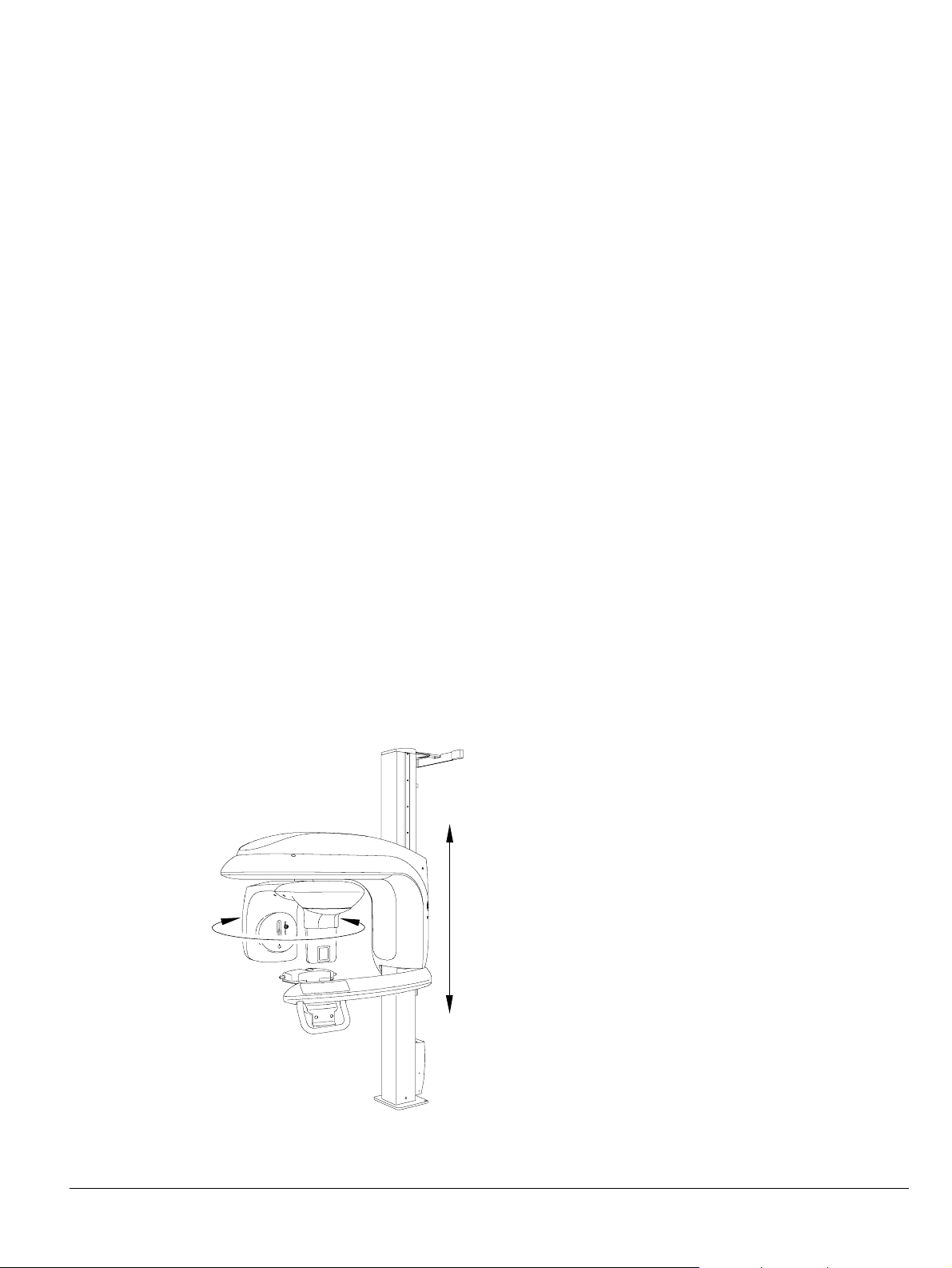
Figure 2-1 illustrates the up and down movement of the Unit mobile component and the 180°
rotation of the rotative arm.
Figure 2–1 KODAK 9000 3D Unit
KODAK 9000 3D Extraoral Imaging System_Installation Guide (SM711)_Ed 01 2–1
Page 12
Functional Overview
Figure 2–2 KODAK 9000 3D Unit functional components
25
19
24
5b
23
22
17
16
15
4
5a
18
20
21
14
5
3
10
9
2
1
8
12
RJ45/1
6
5
RJ45/2
7
1 Unit fixed arm 13 LAN RJ45/2
2 Control panel 14 Sensor
3 Hand grips 15 Generator
4 Temple supports 16 Unit rotativ e arm
11
13
5 Chin rest base 17 Under the head front cover
5 a Panoramic chin rest 18 Under the head back cover
5 b 3D chin rest and forehead support 19 Head cover
6 Unit mains connecting terminal 20 Column side cover
7 Green warning lamp (x-ray emission indicator) 21 Column inside cover
8 Column connecting terminals 22 ON/OFF button
9 X-Ray remote control 23 Wall mounting brackets
10 Door safety switch 24 Wall mounting brackets cover
11 PC hosting the imaging and acquisition software 25 Column upper cover
12 Ethernet outlet RJ45/1
2–2 KODAK 9000 3D D IGITAL IMAGING UNIT OVERVIEW
Page 13
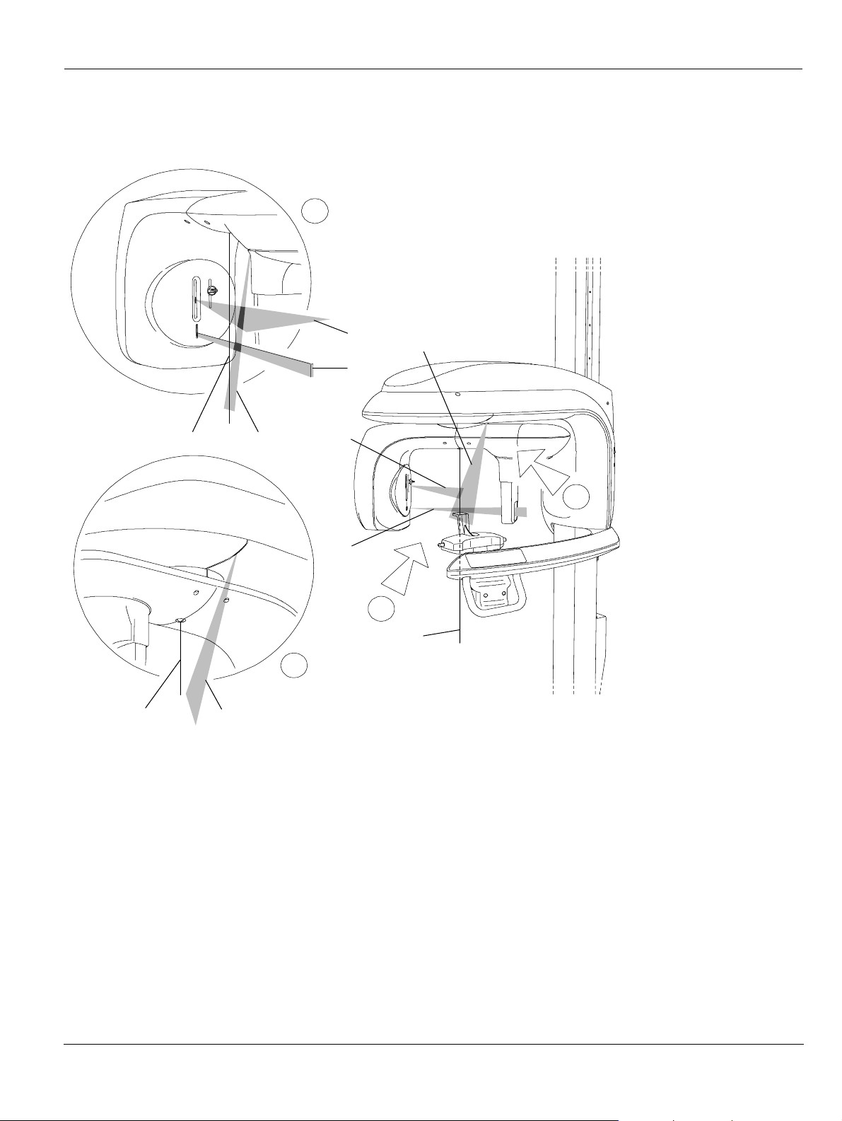
Figure 2–3 KODAK 9000 3D Unit Positioning Laser Beam components
A
Functional Overview
3
4
1
2
B
21
3
4
A
2
B
1
1 3D central positioning laser beam
2 Mid-sagittal positioning laser beam
3 Horizontal positioning laser beam
4 3D Field of View (FoV) positioning
laser beam
KODAK 9000 3D Extraoral Imaging System_Installation Guide (SM711)_Ed 01 2–3
Page 14
Control Panel Overview
Control Panel Overview
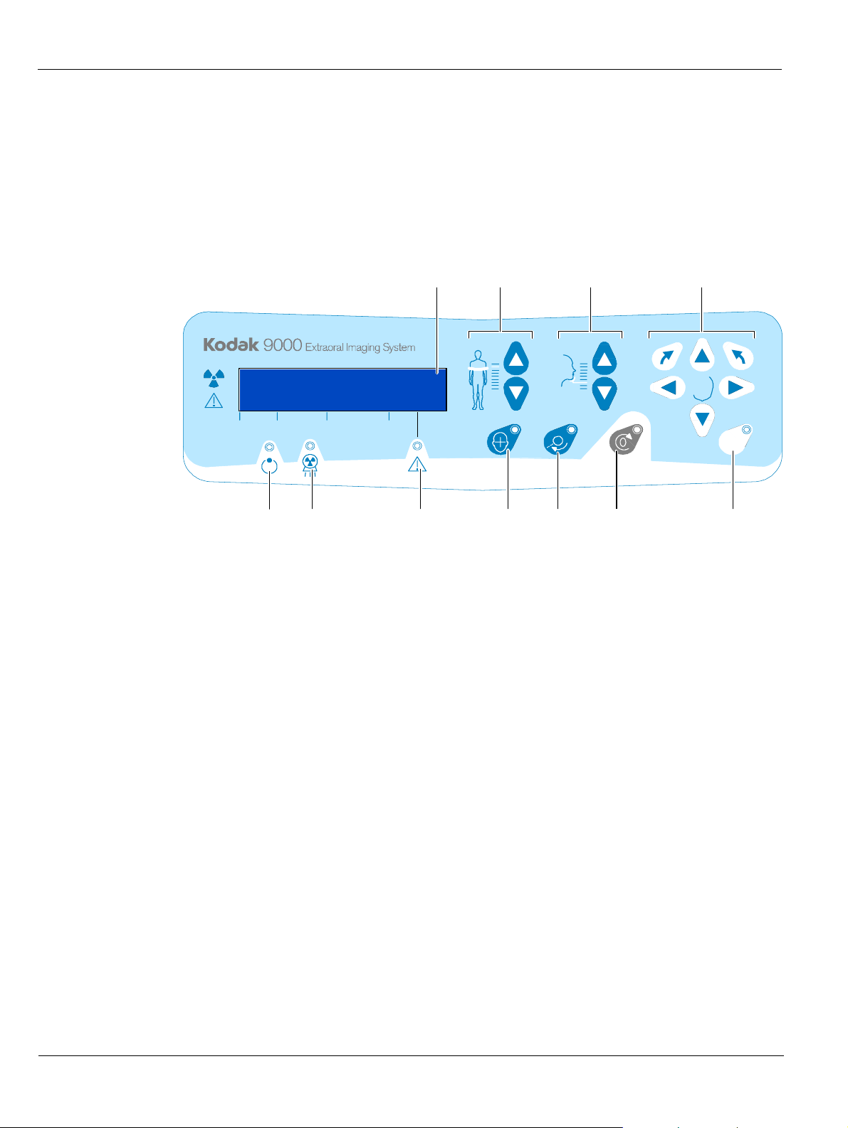
The Control Panel is an alphanumeric digital soft touch console. It allows the operator to
control certain Unit functions. It also displays the operating parameters and error messages.
Figure 2–4 Unit Control Panel
23
5410911
kV
mA S
8
1
1 Height Adjustment button: Adjusts the height of the unit to the height of the
patient.
2 Head Adjustment button: Adjusts the patient head to the x-ray beams.
3 3D Adjustment button: Adjusts the Unit arm movements to correctly position
the patient for 3D acquisition.
4 Laser Beam button: Activates the beams to correctly position the patient.
mem
76
5 3D Position Verification button: Verifies the correct 3D positioning.
6 Reset button: Resets the Unit arm to the initial position to enable the patient to
enter and exit the Unit.
7 3D Memorization button: Memorizes the 3D current positioning parameter
settings that override the default parameters.
8 Display Screen: Displays the current acquisition parameters and the error
messages.
9 Ready Indicator LED: Green indicates the Unit is ready for acquisit ion .
10 X-Ray Emission LED: Yellow indicates x-rays are being emitted.
11 System Status LED: Red indicates error alerts.
2–4 KODAK 9000 3D D IGITAL IMAGING UNIT OVERVIEW
Page 15
X-Ray Remote Control Overview
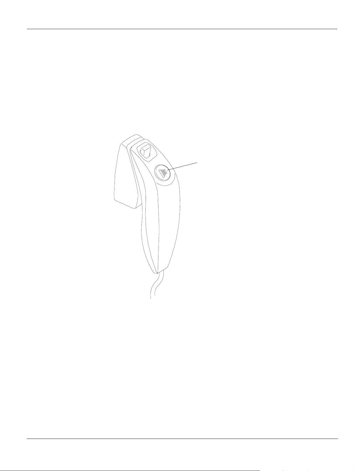
The x- ray remote control enables you to launch a radiological image acquisition via the
exposure button from outside the x-ray room. You must press and hold the exposure button
until the end of acquisition. Premature release of the exposure button interrupts the
acquisition.
Figure 2–5 X-Ray Remote Control
1
X-Ray Remote Control Overview
1 Exposure button: launches image acquisition.
KODAK 9000 3D Extraoral Imaging System_Installation Guide (SM711)_Ed 01 2–5
Page 16

X-Ray Remote Control Overview
2–6 KODAK 9000 3D D IGITAL IMAGING UNIT OVERVIEW
Page 17
Chapter 3
KODAK 9000 3D PACKAGING
Standard Packaging
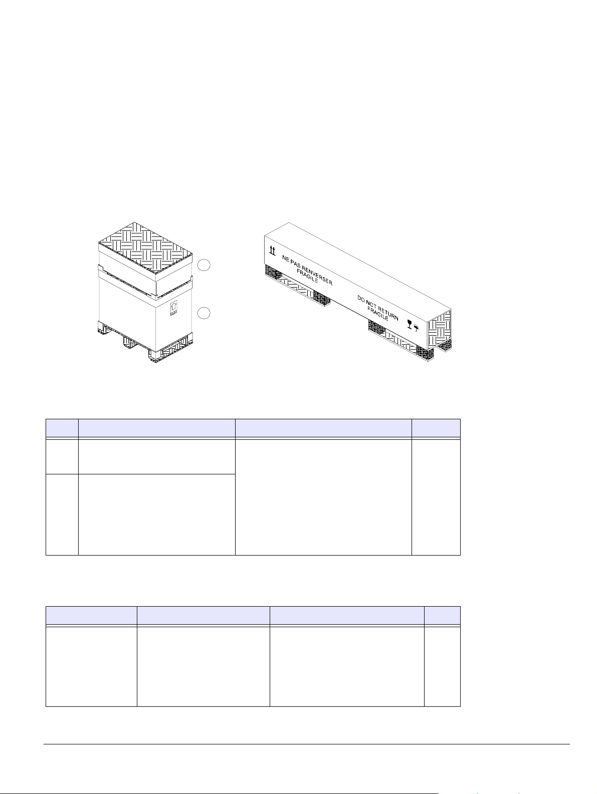
When unpacking the boxes, ensure that you received the following components.
• Head assembly components (A & B)
• Column assembly component
A
B
Table 3–1 Head Assembly Components
Box Components Dimension (cm) Weight
(A)
• Fixed arm
• Unit covers
(B)
• Unit head
• X-ray remote control
800mm (D) x 1200mm (L) x 1540mm (H) 190 kg
• Positioning accessories
• Technical accessories
• Documentation
Table 3–2 Column Assembly Components
Box Components Dimension (cm) Weight
• Unit column
• Wall mounting bracket
Column assembly
• Wall bracket cover
350mm (D) x 2300mm (L) x 460mm (H) 74 kg
• 3 meter mains power cable
• Upper column cover
KODAK 9000 3D Extraoral Imaging System_Installation Guide (SM711)_Ed 01 3–1
Page 18
Head Assembly
Head Assembly
The head assembly is composed of 2 boxes (A & B) superposed.
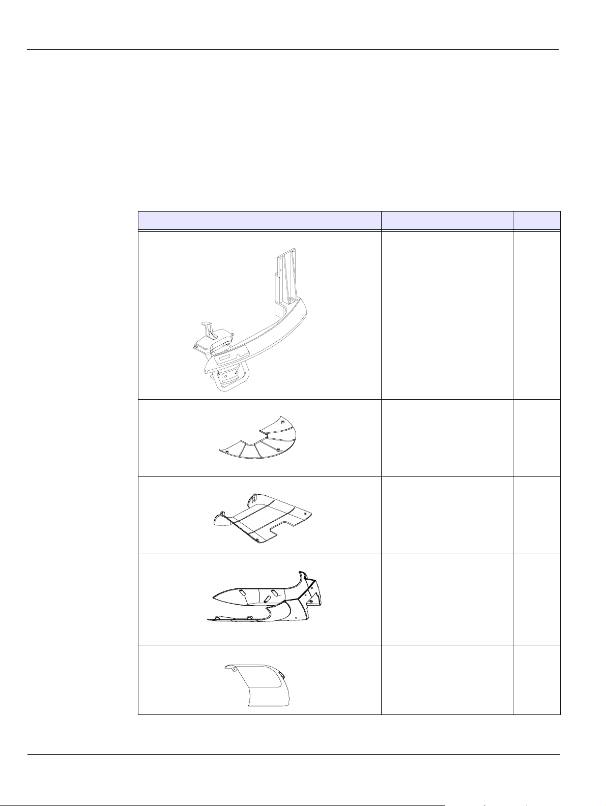
Box (A) Components
Table 3-3 lists the box A components.
Table 3–3 Box (A) Components
Product Description Quantity
Unit fixed arm 1
Under the head front cover 1
Under the head back cover 1
Column side cover 1
Column inside cover 1
3–2 KODAK 9000 3D PACKAGING
Page 19
Box (B) Components
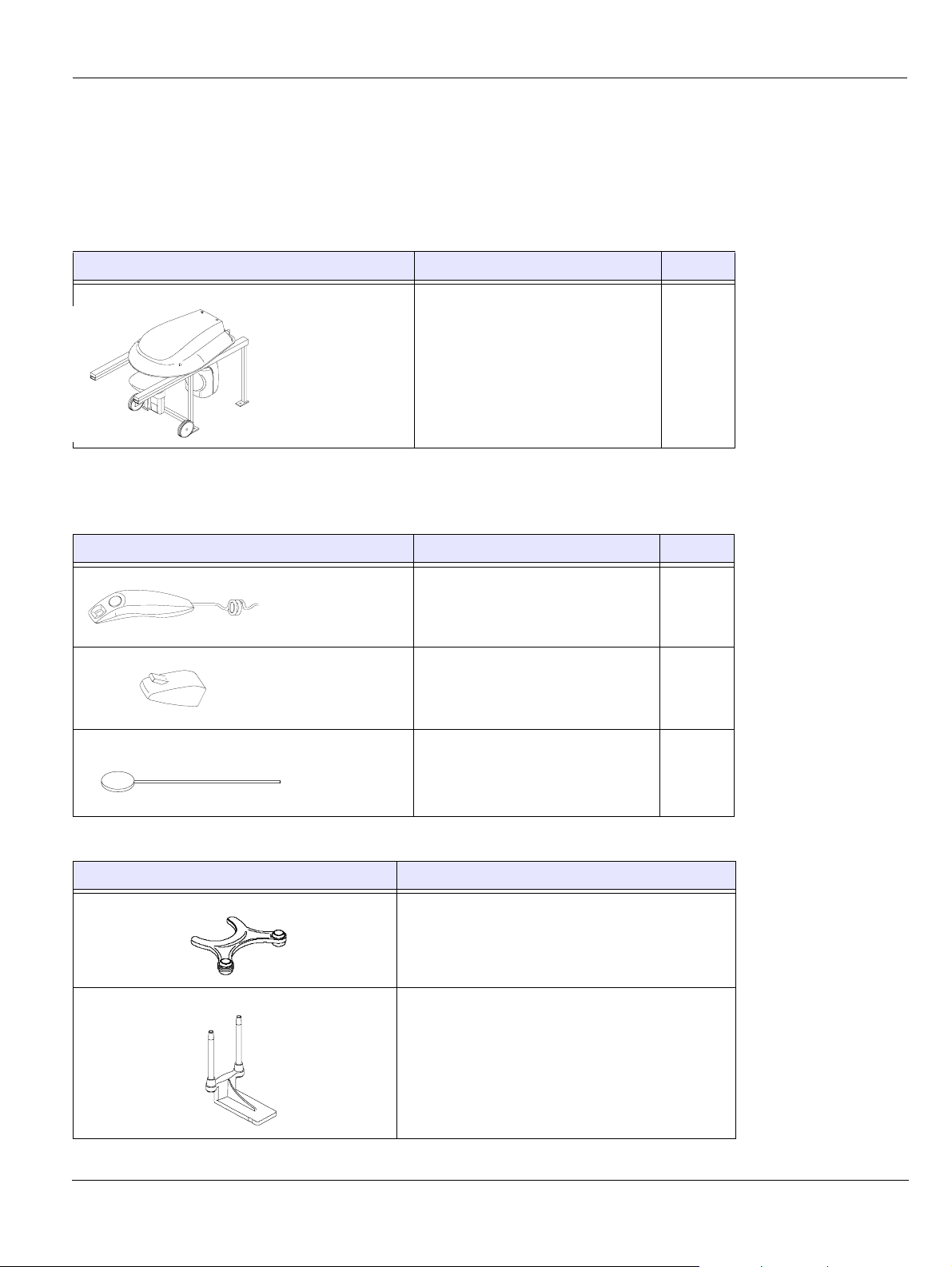
The following Tables list the box B components.
Table 3–4 Unit Head
Product Description Quantity
Table 3–5 Different Components
Head Assembly
3D Head assembly and the head cover 1
Product Description Quantity
X-ray remote control 1
Mounting hook for the x-ray
remote control
A set of right and left temple supports 2
x2
Table 3–6 3D Positioning Accessories and Replacement Parts
Accessory Description
3D bite block
1
3D chin rest
KODAK 9000 3D Extraoral Imaging System_Installation Guide (SM711)_Ed 01 3–3
Page 20
Head Assembly
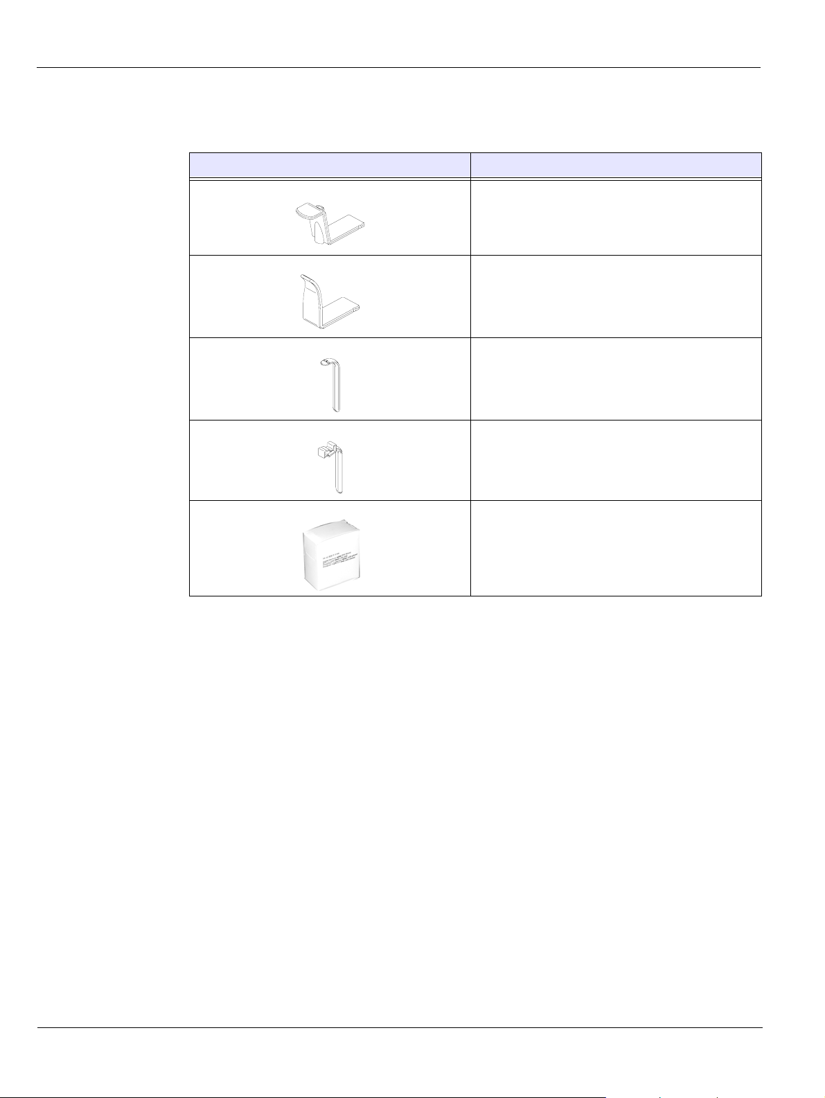
Table 3–7 Panoramic Positioning Accessories and Replacement Parts
Accessory Description
• Panoramic chin rest
• TMJ x2 chin rest
• Sinus chin rest
TMJ x4 nose rest
Panoramic standard bite block
Bite block for edentulous patients
Single use sheaths for bite blocks (500 pcs
box)
3–4 KODAK 9000 3D PACKAGING
Page 21
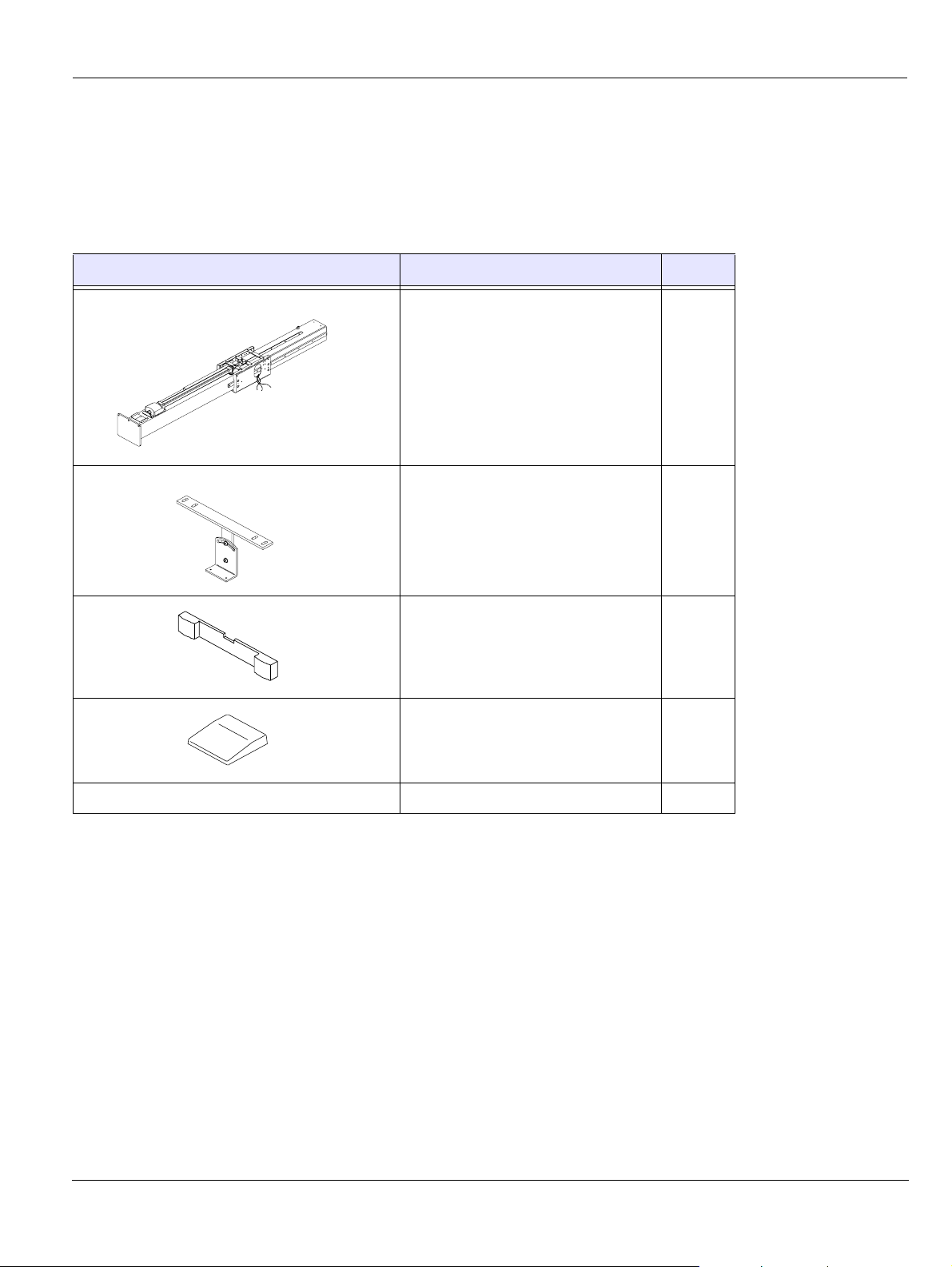
Column Assembly
Table 3-8 lists the column assembly components.
Table 3–8 Column Assembly
Product Description Quantity
Column assembly 1
Wall mounting brackets 1
Column Assembly
Wall mounting brackets cover 1
Column upper cover 1
3 meter mains power cable 1
KODAK 9000 3D Extraoral Imaging System_Installation Guide (SM711)_Ed 01 3–5
Page 22

Column Assembly
3–6 KODAK 9000 3D PACKAGING
Page 23

Chapter 4
SITE PREPARATION BEFORE INSTALLATION
IMPORTANT
Prior to placing the order and before installation, carefully check the
following requirements for the x-ray room.
Standard Compliance
Install the Unit in an x-ray room compliant with all official regulations appli cable to protection
against radiation. This room must reduce the frequency interferences of the 30MHz to 1GHz
band to at least 12db.
Environmental Requirements
Check the following ambient operating condition requirements of the x-ray room before
installing the Unit:
Temperatures: 5 ~35 °C
•
• Relative humidity: 30 ~ 85%
• Atmospheric pressure: 700 ~ 1060 hpa
KODAK 9000 3D Extraoral Imaging System_Installation Guide (SM711)_Ed 01 4–1
Page 24
Unit Dimensions
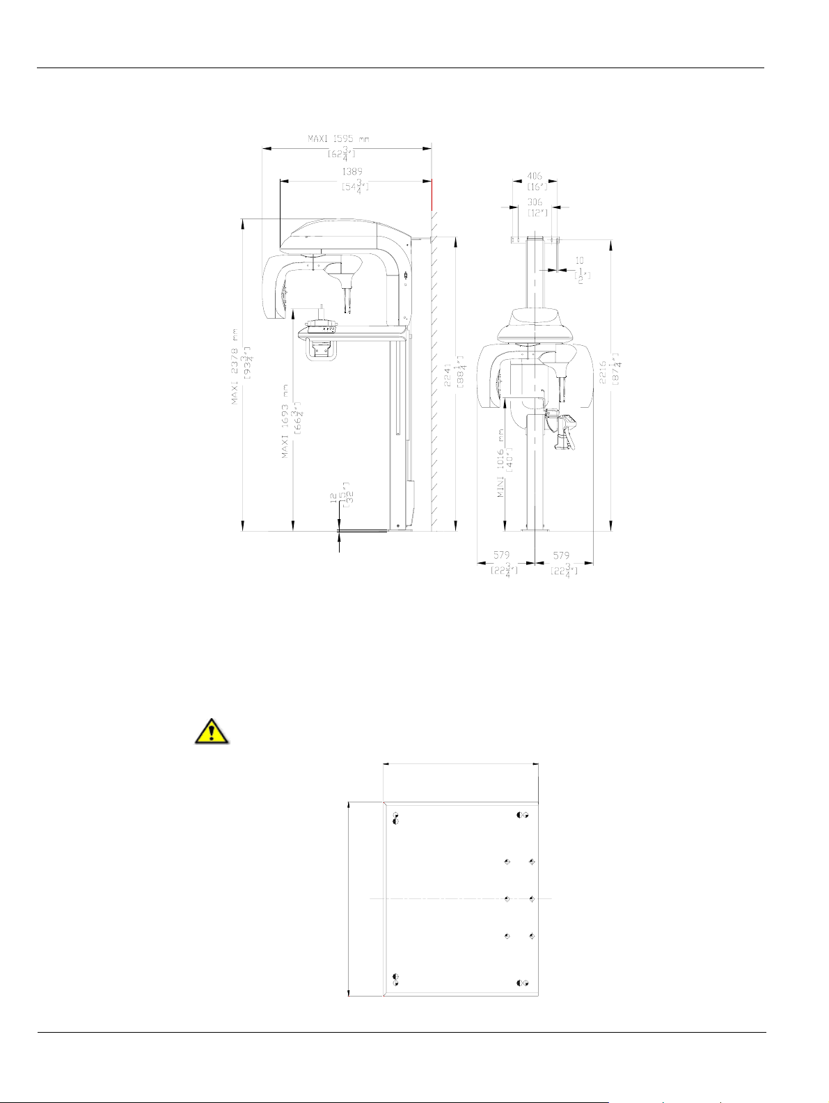
Unit Dimensions
The Unit dimensions illustrated in the above figure are as follows:
• Maximum height of the Unit (2378mm)
• Minimum (1016mm) and maximum (1693mm) height of the chin rest
• Width (1158mm) and depth (1595mm) of the Unit
• Dimensions of the column and attaching parts
WARNING
If you need to add a base plate you must add 15mm to the height of the Unit.
500
600
4–2 SITE PREPARATION BEFORE INSTALLATION
Page 25
Electrical Requirements
WARNING*
You MUST select the operating voltage when placing an order. The
operating voltage CANNOT be modified on site.
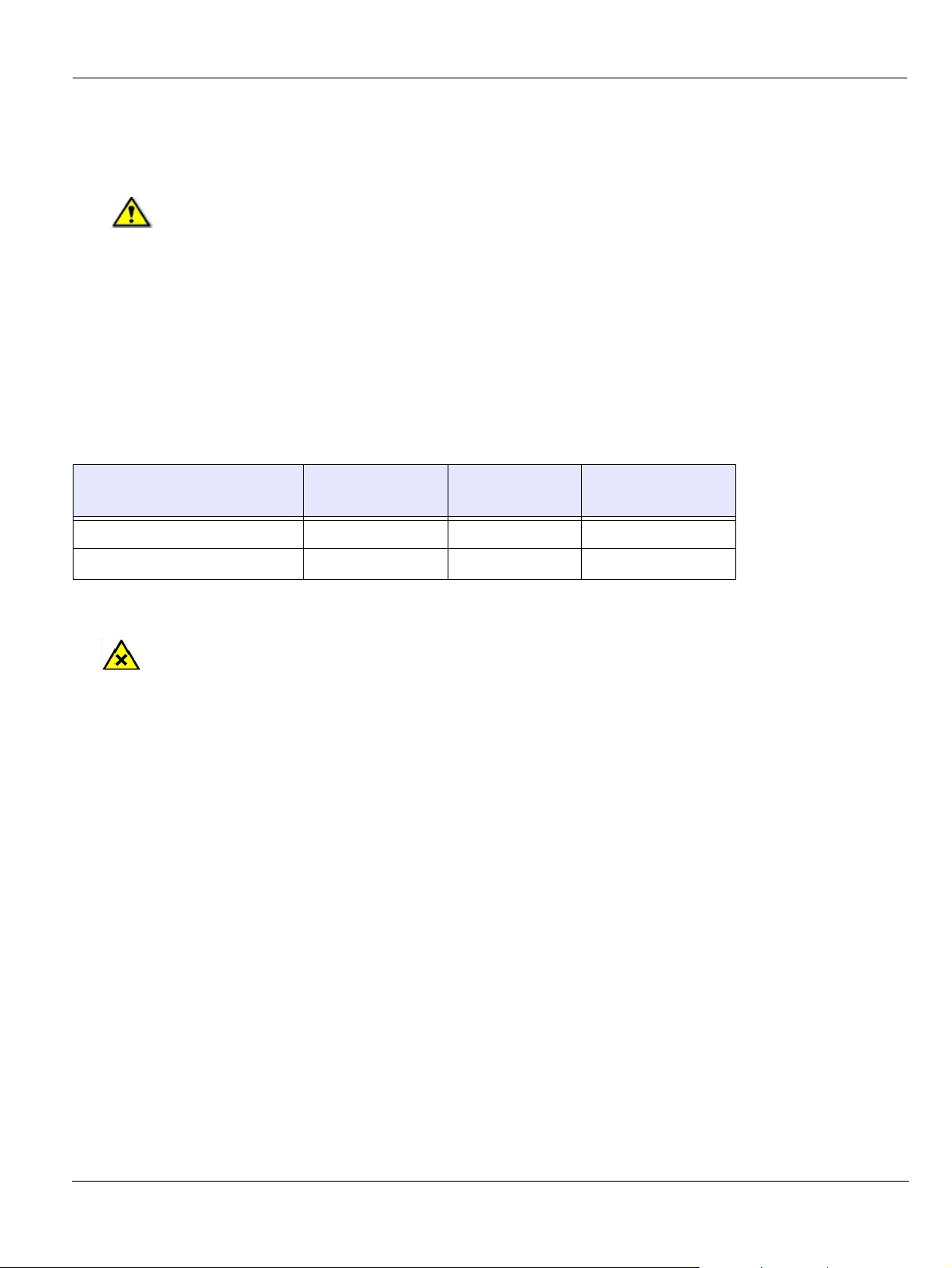
The Unit can operate at:
• 100/110/130 V 50/60 Hz
• 230/240 V 50/60 Hz
Table 4–1 Optional Operating Voltages of the Unit
Electrical Requirements
Nominal voltage *
(no load)
100 V - 130 V 90 V 143 V 20 A
230 V - 240 V 207 V 264 V 10 A
CAUTION
The power supply line must be equipped with a connection box that ensures a constant connection. It must not be possible to connect the Unit to the power supply without using a tool. The Unit must be protected against any accidental disconnection.
If other units are installed on the same line, interference and voltage fluctuations can cause the
radiological Unit to operate abnormally . We strongly recommend that a separate electrical line
be dedicated to supply power to the KODAK 9000 3D Unit.
This line should be protected by a circuit breaker with a maximum current of:
• 16 A at 230/240 V
• 20 A at 110/130 V
• A differential circut breaker of 30 mA
Minimum Maximum
Maximum line
current
KODAK 9000 3D Extraoral Imaging System_Installation Guide (SM711)_Ed 01 4–3
Page 26
Electrical Requirements
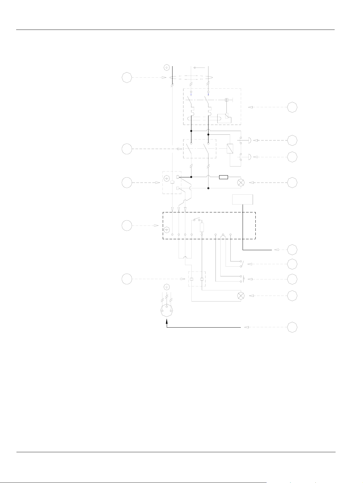
Figure 4–1 Electrical Diagram of the X-ray Room and KODAK 9000 3D Connections
G NL
1
2
3
13
4
6
8
7bis
L
1A
5
N
RJ45
K9000
N
L
1A
12
10
9
L
N
7
11
1 General mains 7bis X-ray warning lamp connecting
2 Differential circuit breaker 8 Column connecting terminals
3 Red color actuator emergency stop push-button 9 X-ray remote control
4 Red color actuator emergency stop push-button 10 Door safety switch
5 Red warning lamp, power ON indicator 11 Mains outlet (for electric tools)
6 Unit mains connecting terminal 12 Ethernet outlet (RJ45/1)
7 Green warning lamp, x-ray emission indicator 13 Contactor
4–4 SITE PREPARATION BEFORE INSTALLATION
terminal
Page 27
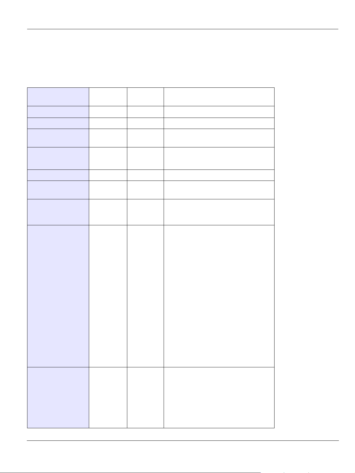
A single-phase alternating current power supply is required and the electrical installation
specifications should be as follows:
Table 4–2 Electrical Installation Specifications
Electrical Requirements
Supply Voltage
230V/240V
100V/110V/
130V
Frequency 50/60 Hz 50/60 Hz
Electrical supply 6 kW 6 kW
Line current
16A 20A
required
Cable cross-section
according to length
For 30 m:
2.5 mm2
For 10 m:
2.5 mm2
Max. line impedance 0.5 0.12
Differential circuit
breaker (2)
Maximum current to
trip circuit breaker
30 mA 30 mA
16A 20A Protect the power supply line with a
differential circuit breaker that trips at
maximum current.
Specifications of 2
red color actuator
emergency stop
250V 6A
UL listed
250V 6A
UL listed
• Install these stop push-buttons to
push-button
(3) and (4)
• Locate (3) inside the x-ray room,
• Locate (4) outside the x-ray room,
• Maintain them in OFF (open)
simultaneously, switch off the
current to the active conductors of
the radiological installation and
exclude any other electric
equipment.
near the Unit, for the patient to
quickly cut the power supply if
necessary.
near the x-ray remote control for
the operator to quickly cut the
power supply if necessary.
position until a deliberate action is
performed.
Specifications of the
warning lamps
(5) and (7)
60 W 60 W
KODAK 9000 3D Extraoral Imaging System_Installation Guide (SM711)_Ed 01 4–5
• Locate the red warning lamp (5)
outside the x-ray room to indicate
the Unit is active (1 lamp at each
access point).
• Locate the green warning lamp (7)
outside the x-ray room to indicate
the x-ray emission.
Page 28
Electrical Requirements
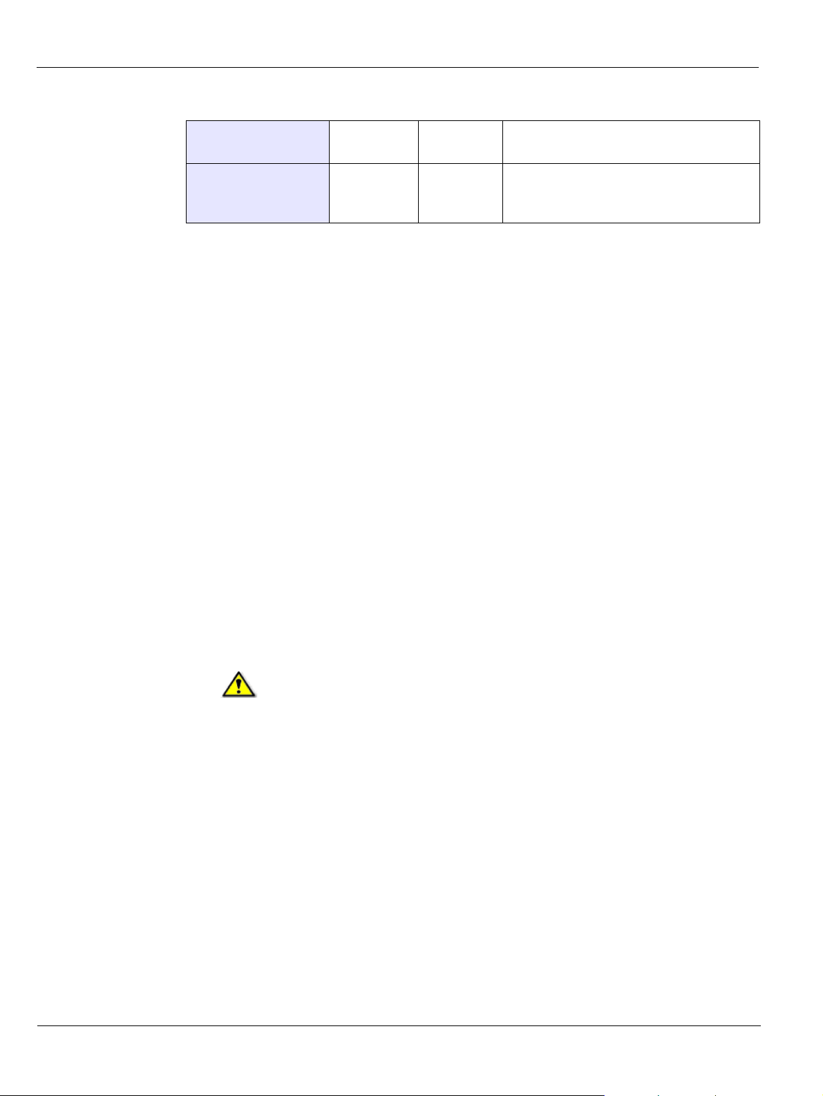
Table 4–2 Electrical Installation Specifications
Contactor (13) 16A-250V
UL listed
Door Safety Switch
1A / 250V 1A / 130V Optionally, connect the door safety
(9)
Use the following switches:
Emergency Stop Switch:
Manufacturer: Cutler-Hammer
Ref:
Contactor:
Manufacturer: Telemecanique
20A-250V
UL listed
switch (9) that deactivates the x-ray
remote control if the door remains open.
• E22AT111
• E22AT112
Ref: LC1 D4011
• F6 (110/130 V - 60 Hz)
• P5 (230/240 V - 50 Hz)
• U6 (230/240 V - 60 Hz)
IMPORTANT
If you cannot use the above manufacturer devices, use an equivalent
emergency switch and contactor in the UL list with the same specifications.
For more information, see UL 2601.1 clause 22.7.
4–6 SITE PREPARATION BEFORE INSTALLATION
Page 29
X-Ray Room Requirement
IMPORTANT
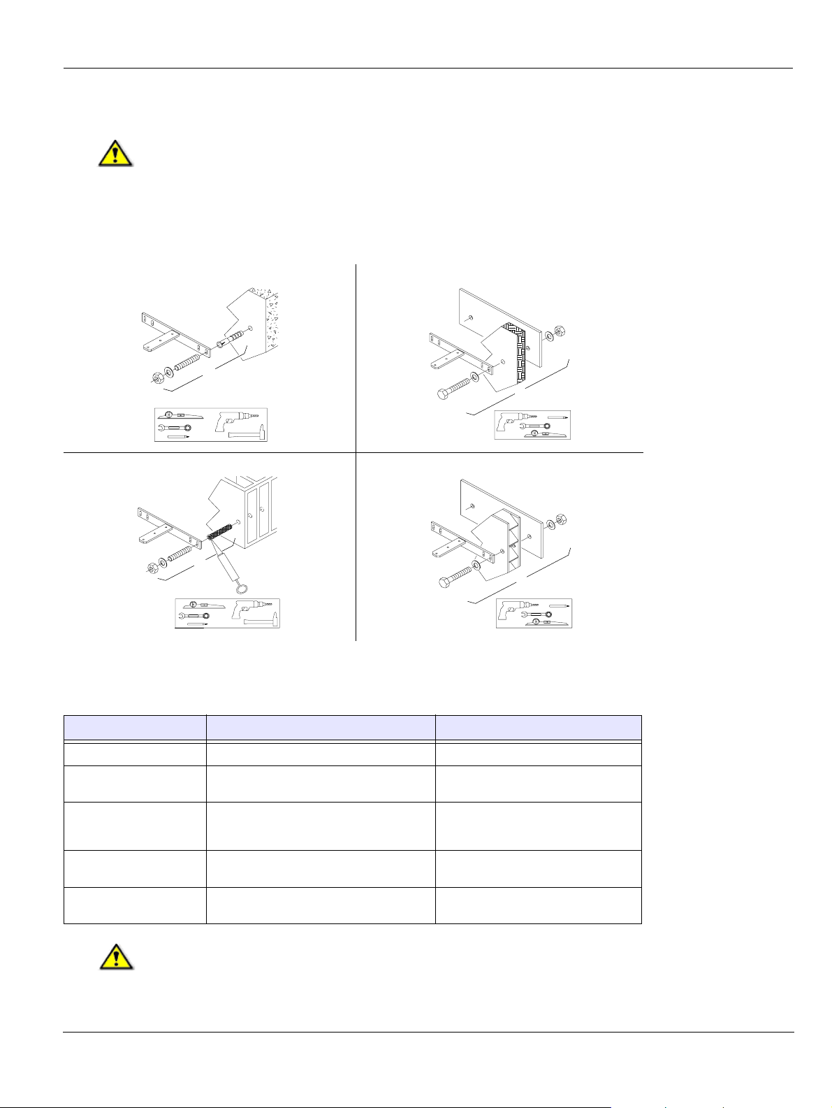
Use an appropriate wall fixing system suitable for the type of wall
construction. See the examples below.
The following illustrations provide examples of wall types and fixations.
2 x
X-Ray Room Requirement
2 x
16 mm
2 x
16 mm
16 mm
2 x
16 mm
Table 4–3 X-Ray Room Requirements
Room Components Minimum Requirement Comments
Width of the door 75 cm (30")
Height of the ceiling 240 cm (95") If needed, a shorter column is possible
Strength of the wall Withstanding an extraction force of 150 kPa
at each point of attachment.
Load-bearing capacity of
500 kg/m2 The floor must be solid and flat.
the floor
Required space for the
1500 (L) x 2000 (D) x 2400 (H) mm
KODAK 9000 3D Unit
by special order.
It is the responsibility of the installer to
choose an appropriate fixing system that
withstands the extraction force.
IMPORTANT
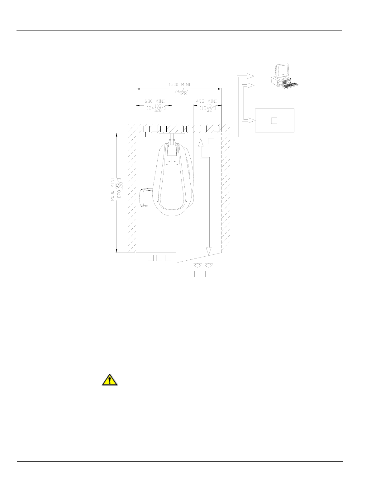
Install the Unit where a minimum amount of space is provided to allow
easy access for the patient or the maintenance technician (see Figure 4-2).
KODAK 9000 3D Extraoral Imaging System_Installation Guide (SM711)_Ed 01 4–7
Page 30
X-Ray Room Requirement
Figure 4–2 Minimum X-Ray Room Space Configuration
12 10
9
57bis
6
11
3
RJ45/1
RJ45/2
13
910
4
57
3 Red color actuator emergency stop push-button 9 X-ray remote control
4 Red color actuator emergency stop push-button 10 Door safety switch
5 Red warning lamp, power ON indicator 11 Mains outlet (for electrical tools)
6 Unit mains connecting terminal 12 Ethernet outlet (RJ45/1)
7 Green warning lamp, x-ray emission indicator 13 Local Area Network (LAN), (RJ45/2)
7bis X-Ray warning lamp connecting terminal
WARNING
You MUST prepare the appropriate electrical requirements and
configurations of the x-ray room before installing the Unit. You MUST
locate separately the following low voltage and high voltage connections:
- Low Voltage: (12), (9), (10)
- High Voltage: (6), (5), (7bis)
4–8 SITE PREPARATION BEFORE INSTALLATION
Page 31
PC System Requirements
This section specifies the minimum PC system requirements for KODAK 9000 3D digital
imaging software.
IMPORTANT
It is MANDATORY to check that the PC system configuration is
compatible with the PC system requirements for the KODAK 9000 3D
software. If necessary you MUST update your PC system configuration.
KODAK 9000 3D MUST be connected to the PC via a point-to-point
Ethernet link and not via a LAN. DO NOT place the PC and the peripheral
equipment connected to it in the immediate vicinity of the patient in the
Unit. Leave at least 1.5 m distance from the Unit. The PC and the
peripheral equipment must conform to the IEC 60950 standard.
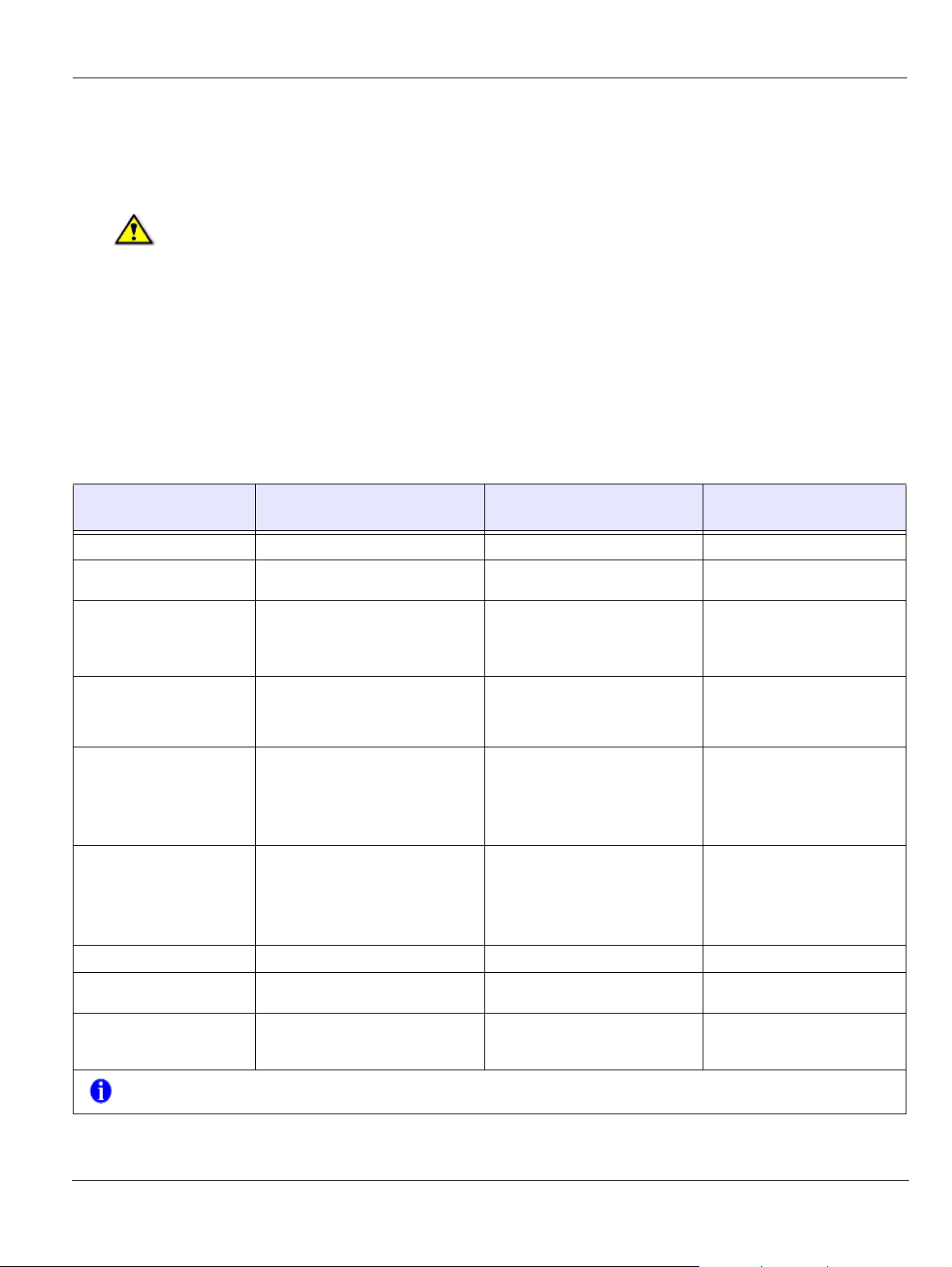
Table 4–4 Minimum PC System Requirements
PC System Requirements
Item
CPU 2 GHz Intel Duo Core 3 GHz Intel Pentium 4
RAM 2 GB 2GB RAM has a major impact on
Hard disk drive
Minimum Workstation Image
Viewing Requirements
• 1.2 GB for software installation
Minimum Workstation
Acquisition Requirements
1.2 GB for software installation
Comments
system performance.
• 80 GB free space to use the
software
Graphic board Nvidia / ATI based board supporting
Monitor
Open Glide 1.2 with 256 MB of video
RAM on AGP x8 video bus (example:
Nvidia GeForce 6800 GT)
• 1 monitor
• 17" or larger
• 1024 x 768 minimum screen
resolution - 32 bits color mode
Operating system
• Windows 2000 SP4
• Windows XP Home / Pro
edition SP2
• Windows Vista 32 bits
Ethernet interface 1 Ethernet interface 2 Ethernet interfaces (100Mbits)
Nvidia board on PCI Express video
bus, minimum GeForce 8800 GTS
640 MB of video RAM, or Quadro
FX 4600 768 MB of video RAM
• 1 monitor
• 17"
• 1024 x 768 minimum screen
resolution
• Windows 2000 SP4*
•
Windows XP Home / Pro
edition SP2
• Windows Vista 32 bits*
The video RAM has major impact
on system performance.
Your monitor is a vital component
in displaying quality images.
Low-quality screens will prevent
you from proper diagnoses and
treatment.
CD/DVD drive A CD-ROM drive is required to install
the product.
Backup Media Removable/portable, external hard
disk drive
* NOTE: The indicated operating systems consid er ably increase the 3D volume image reconstruction time. The normal
duration of a few minutes is increased by more than an hour.
KODAK 9000 3D Extraoral Imaging System_Installation Guide (SM711)_Ed 01 4–9
A CD-ROM drive is required to
install the product.
Removable/portable, external hard
disk drive.
We strongly recommend a daily
backup of x-ray images and
patient records.
Page 32

PC System Requirements
4–10 SITE PREPARATION BEFORE INSTALLATION
Page 33
Chapter 5
INSTALLING THE KODAK DENTAL IMAGING SOFTWARE
Before installing the KODAK Dental Imaging Software, check that:
• The computer has all the PC system requirements
• You have the software CD
To install the KODAK Dental Imaging Software, follow these steps:
1. Insert the software CD in the CD-ROM drive of the computer. Wait for the installation program to start. If the program does not start automatically, click
Start > Run and enter D:\setup.exe if D is the letter for the CD-ROM drive, or the letter
of the relevant drive on the computer.
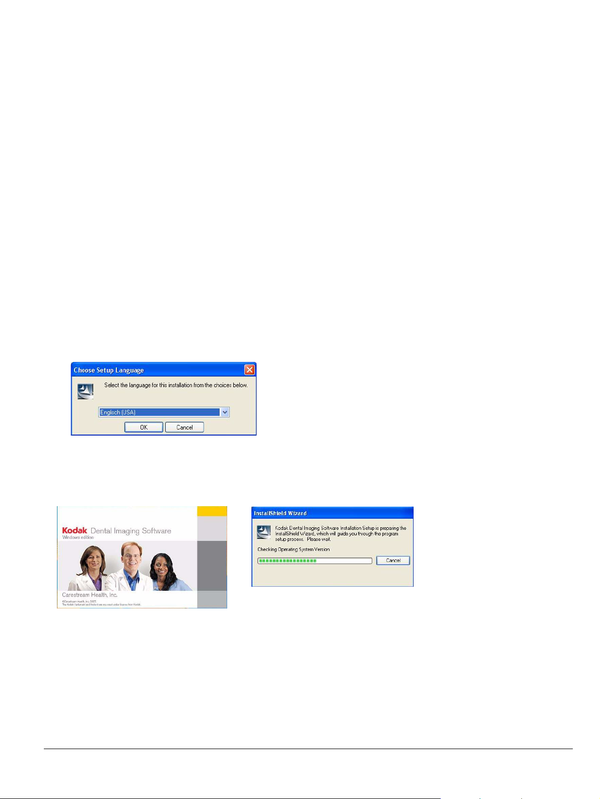
2. The Choose Setup Language dialog box is displayed. Select the installation language and click OK.
3. The Kodak Dental Imaging Software welcome page and the InstallShield wizard are displayed.
KODAK 9000 3D Extraoral Imaging System_Installation Guide (SM711)_Ed 01 5–1
Page 34
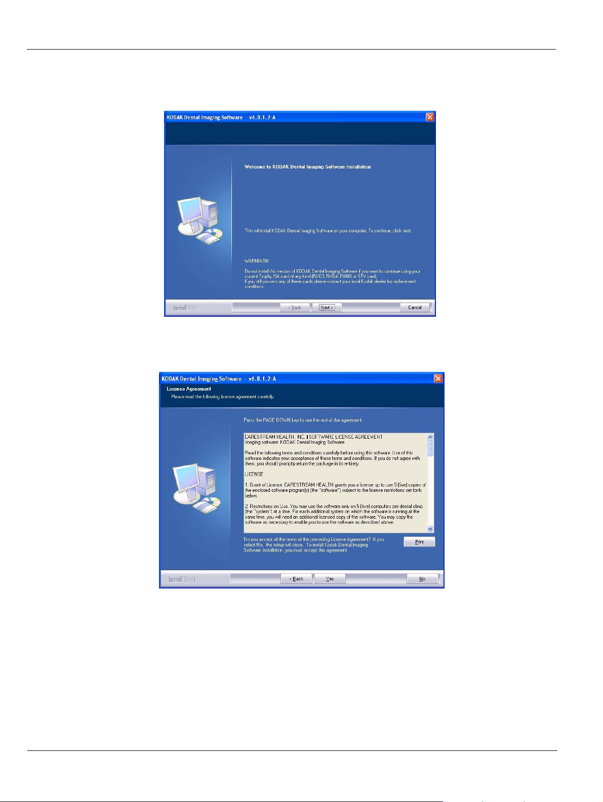
4. The Welcome to KODAK Dental Imaging Software Installation dialog box is displayed. Click Next to launch the installation.
5. The Li cense Agreement dialog box is displayed. Accept and click Yes.
5–2 INSTALLING THE KODAK DENTAL IMAGING SOFTWARE
Page 35
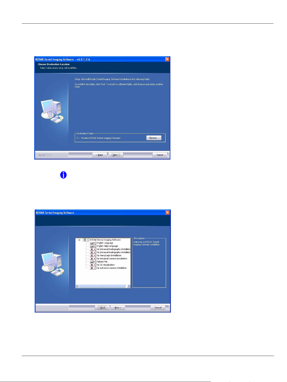
6. The Choose Destination Location dialog box is displayed. Click Next if you accept the
default destination folder (c:\program files\Kodak\Kodak Dental Imaging Software) or
browse to choose another destination folder.
NOTE
If you are upgrading the software, the default destination folder is the
previously selected destination folder.
7. The KODAK Dental Imaging Software dialog box is displayed.
KODAK 9000 3D Extraoral Imaging System_Installation Guide (SM711)_Ed 01 5–3
Page 36
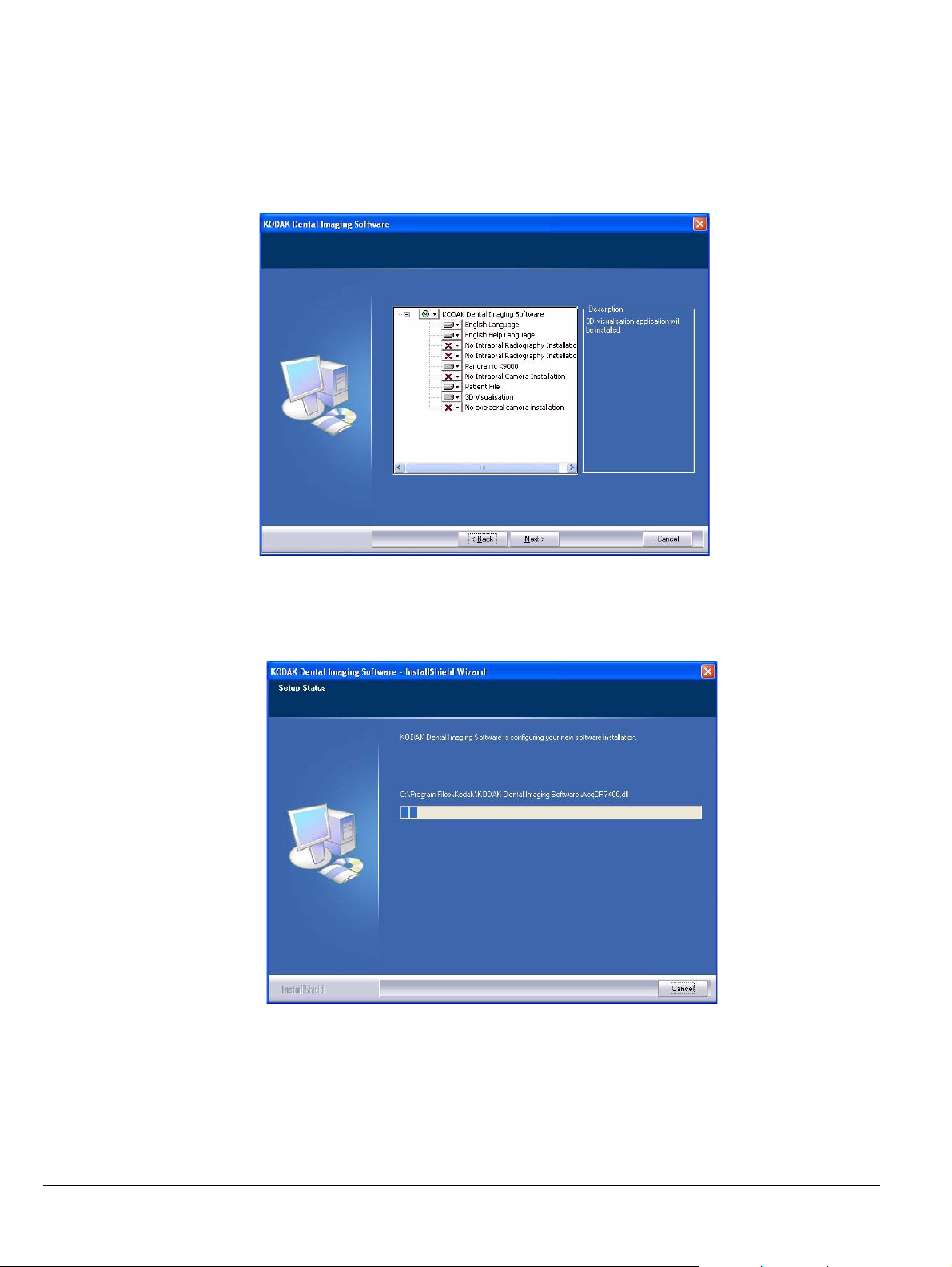
The Patient file is selected by default but you must select the radiological device. Click on
the drop-down list of No Pano/Ceph Installation and select Panoramic K9000. Click on
the drop-down list of No 3D Visualization and select 3D Visualization. Check that you
have selected correctly.
Click Next to begin the installation.
8. The InstallShield Wizard is displayed. Let the installation process run automatically.
5–4 INSTALLING THE KODAK DENTAL IMAGING SOFTWARE
Page 37
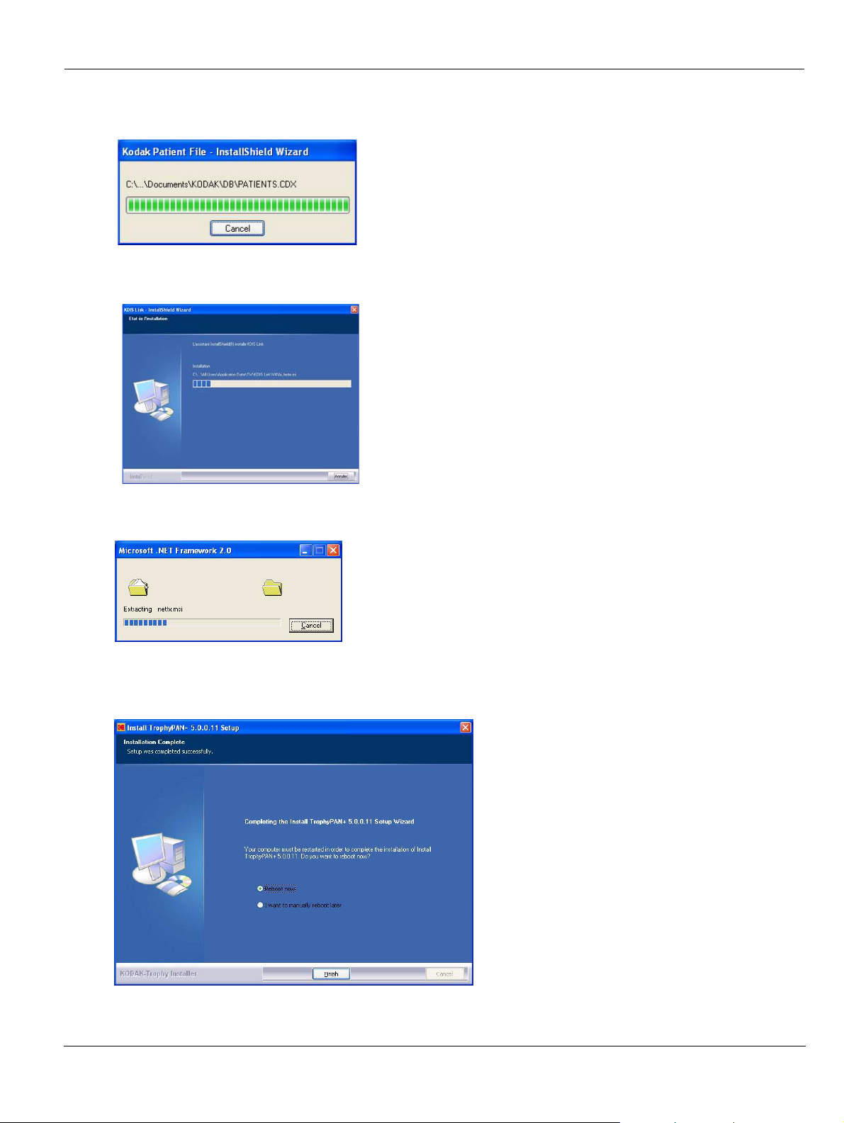
The Kodak Patient file - InstallShield Wizard is displayed while the patient files are
installed on the hard drive..
The KDIS Link - InstallShield Wizard is displayed while the KDIS link is installed on
the hard drive.
The Microsoft .NET Framework 2.0 is displayed while this software is being installed
on your hard disk for 3D visualization.
The Installation Complete dialog box is displayed when th e installation is finished. Click
Reboot now and click Finish.
KODAK 9000 3D Extraoral Imaging System_Installation Guide (SM711)_Ed 01 5–5
Page 38
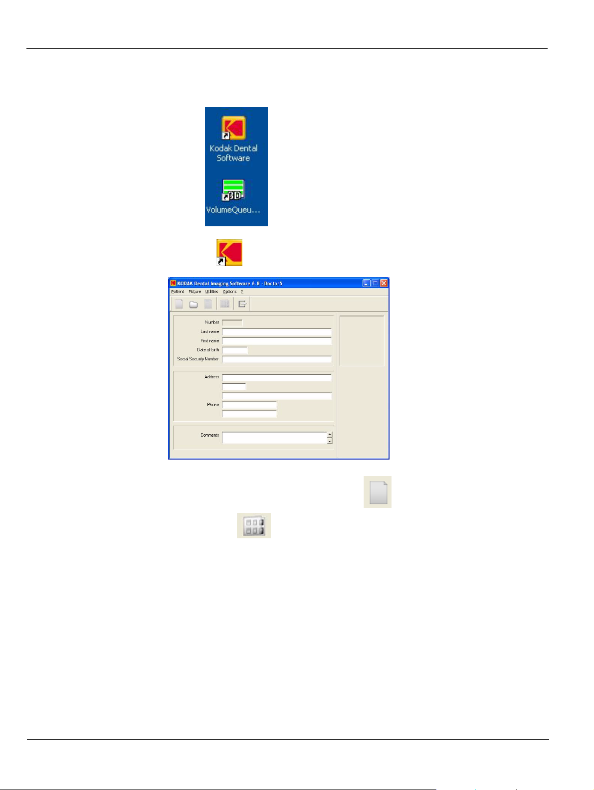
9. The KODAK Dental Software and 3D Volume Queu... icons are installed on your desktop after the reboot.
10. Double-click to open the Patient Window.
11. Create a patient record. From the toolbar, click and enter the required patient
information. Click to access the Imaging Window.
5–6 INSTALLING THE KODAK DENTAL IMAGING SOFTWARE
Page 39
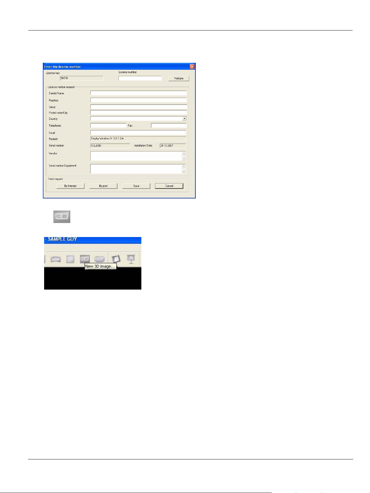
12. The Enter the licence number dialog box is displayed. Enter the licence number and click Validate if you have the licence number or click Cancel to continue.
13. The icon appears on the toolbar of the Imaging Window. The installation is finished.
KODAK 9000 3D Extraoral Imaging System_Installation Guide (SM711)_Ed 01 5–7
Page 40

5–8 INSTALLING THE KODAK DENTAL IMAGING SOFTWARE
Page 41
Chapter 6
INSTALLING THE UNIT
Tool Requirements
The installer must supply the following tools:
• Power drill
• Screws and heavy duty fixings
• Spirit level
• Measuring tape
• Cutter
• Metric Allen keys
• Metric spanners
IMPORTANT
The tool references mentioned in this manual are ISO tool
references.
Technical Staff Requirements
The installation requires the following number of technicians:
Unit Component Technicians
Head 3
Column 2
Fixed arm 2
KODAK 9000 3D Extraoral Imaging System_Installation Guide (SM711)_Ed 01 6–1
Page 42
Opening the Boxes
Opening the Boxes
To unpack the boxes, follow the instructions for each box.
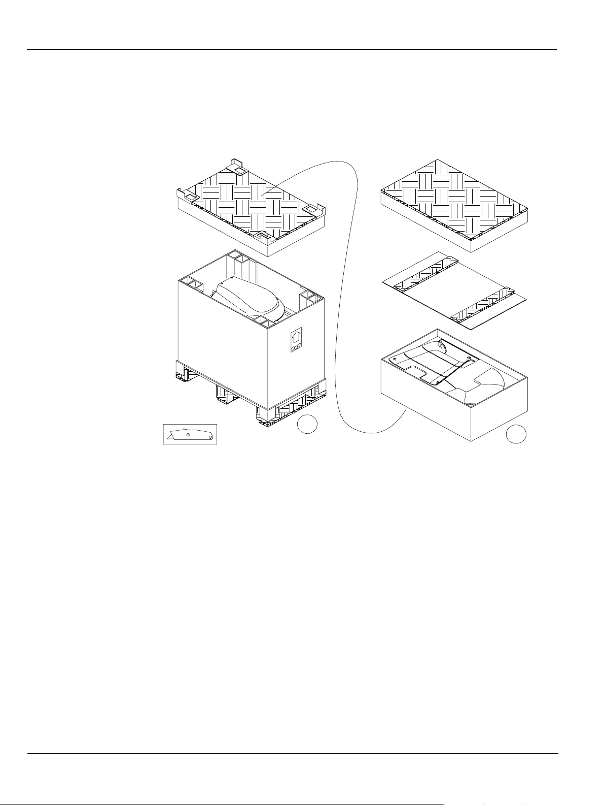
Opening the Head Assembly Box
B
Before opening the head assembly box make sure that you have the required tool.
To open the head assembly box, follow these steps:
1. Remove the upper cardboard from the packaging and lift off the packaging carton. DO NOT cut through the cardboard. Remove the upper box (A).
2. Remove the upper cardboard of the lower box (B). Remove with the help of 3 persons the Unit head transport pallet and place it on the ground. Remove the other component boxes.
3. Release the 4 screws securing the metal transport trolley frame to the pallet. Place the transport trolley with the Unit head at the side of the pallet. You can now safely transport the Unit head.
A
6–2 INSTALLING THE UNIT
Page 43
Opening the Column Assembly Box
Opening the Boxes
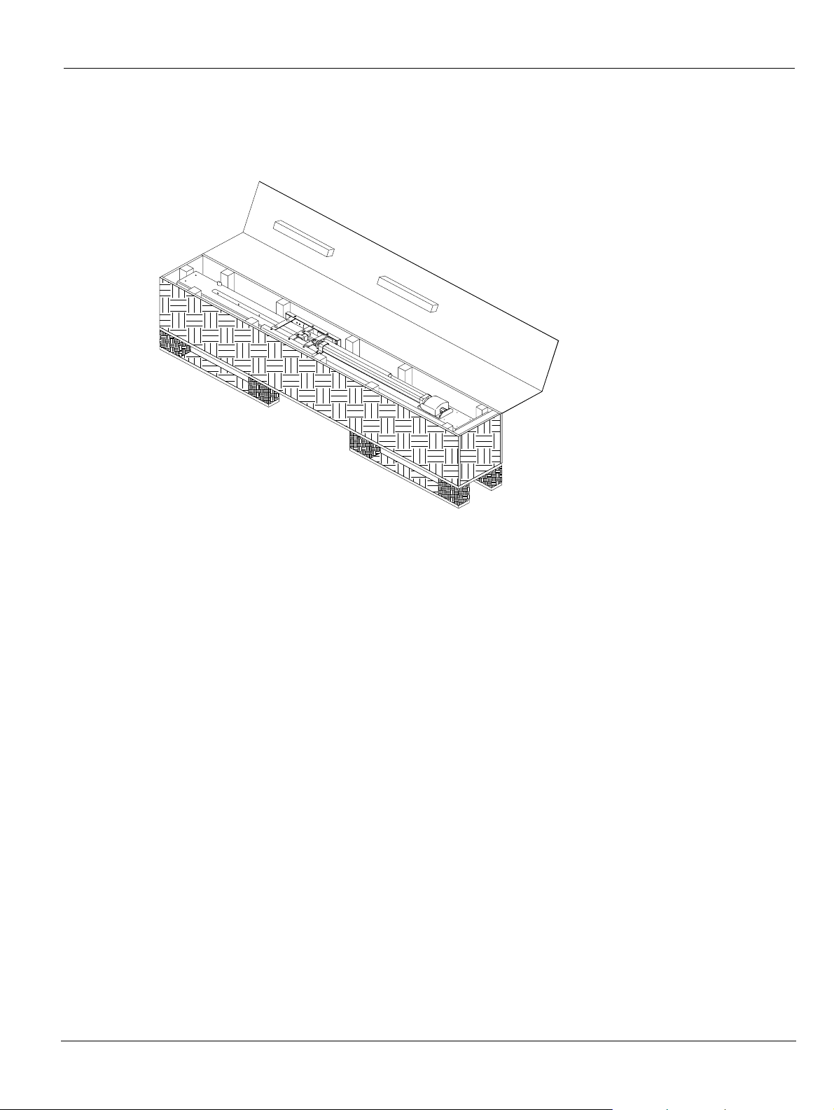
Before opening the column assembly box make sure that you have the required tool.
To open the column assembly box, follow these steps:
1. Open the carton from the side.
2. Remove with the help of 2 persons the column from its box, using one at each end of the column.
3. Place the column on the floor in a horizontal position. Unwrap the column.
KODAK 9000 3D Extraoral Imaging System_Installation Guide (SM711)_Ed 01 6–
Page 44
Installing the Unit
Installing the Unit
Before installing the Unit, check that you have:
• All the necessary tools
• All the cables
• All the switches
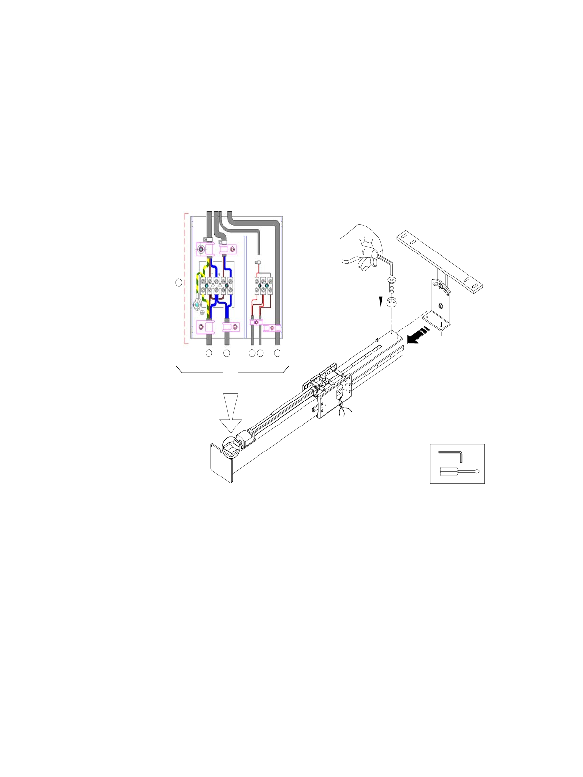
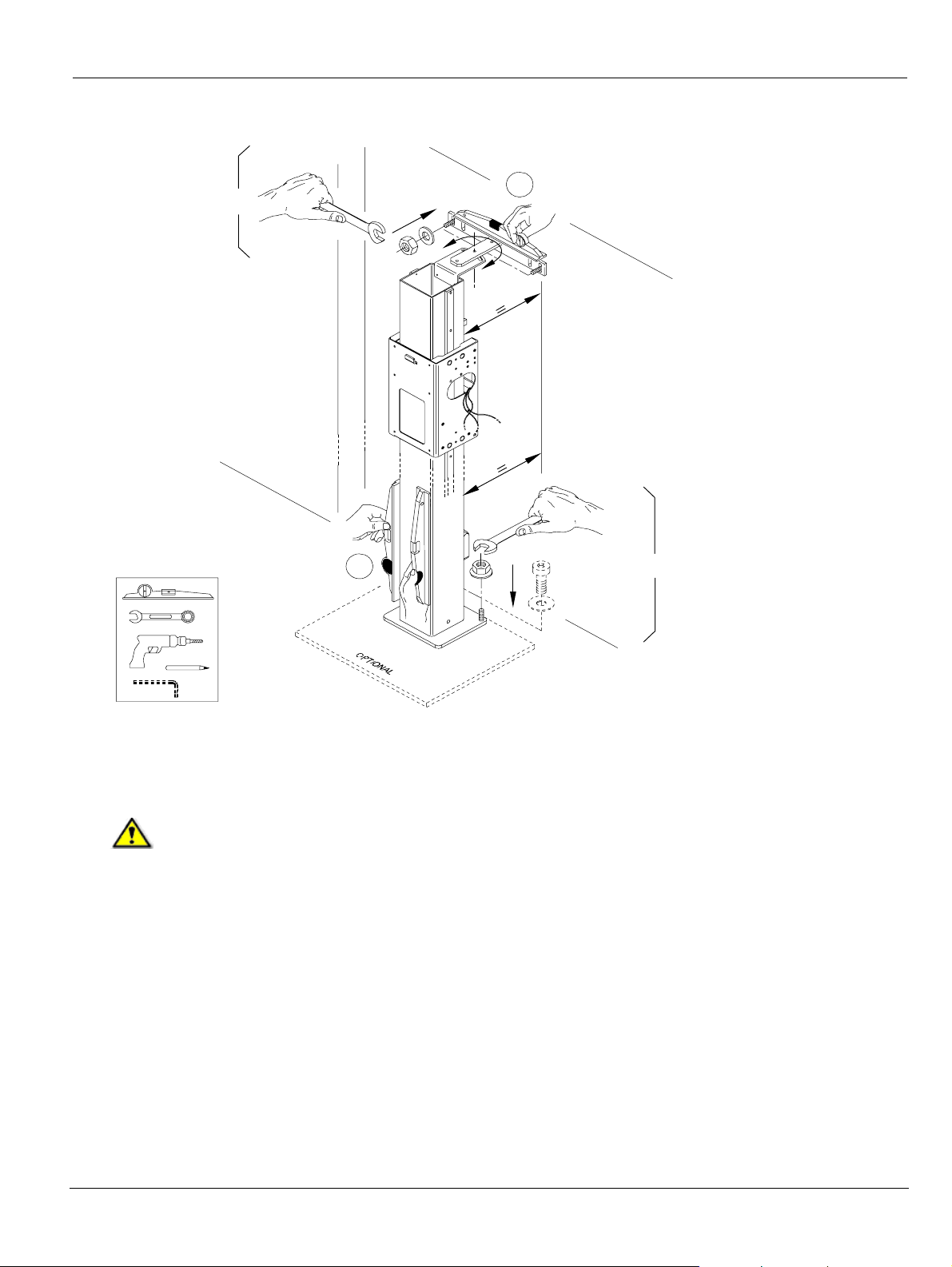
Installing the Column
8
x2
6 7 9 10 12
2
RJ45
6 mm
To install the column, follow these steps:
1. While the column is still on the floor, in a horizontal position, fit the wall bracket lips
inside the column and tighten the 2 screws. If necessary, attach the column to the steel
base plate at this time.
2. Connect the following wiring in the column connecting terminal (8):
• Unit mains connecting terminal (6)
• Green lamp x-ray emission indicator (7)
• X-ray remote control (10)
• Door safety switch (9) (optional)
• Ethernet outlet (12)
6–4 INSTALLING THE UNIT
Depending on the standards in force in your country, we recommend that you also provide
the door safety switch (10).
Page 45
Installing the Unit
A
3
x2
6 mm
A
x3
16
x3
4
3. Place the column in a vertical position, taking care not to trap any cables between the
column and the floor. Hold the mounting bracket against the wall at the top of the col umn
and mark the position of the fixing holes. Move the column to one side and drill the holes.
IMPORTANT
You MUST fix the column to the wall. Use the appropriate wall fixing
system suitable for the type of wall construction.
Attach the mounting bracket to the wall and check that the column is correctly positioned
using a spirit level (A); then, screw the mounting brackets securely to the wall.
4. Mark the position of the fixing holes at the base of the column. Move the column slightly
forward to drill the holes. Place the column in position. Check that the column is correctly
positioned using a spirit level (A) and screw the base to the floor tightly.
You can use the optional base plate if:
• The floor is inappropriate for column fixation.
• The client requests no floor fixation.
The column is ready for the Unit head attachment.
KODAK 9000 3D Extraoral Imaging System_Installation Guide (SM711)_Ed 01 6–
Page 46
Installing the Unit
Installing the Head
5 mm
3 mm
6
5
x4
A
x2
A
x2
6
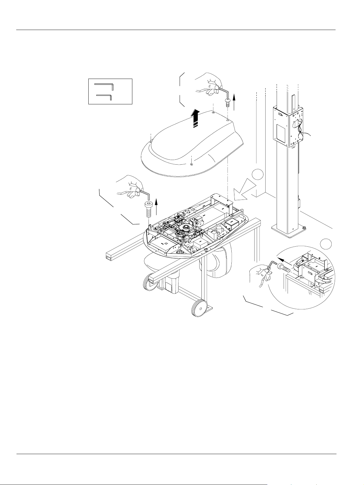
To install the head, follow these steps:
5. Remove the head cover by unscrewing the 4 screws that attaches the head cover to the head chassis.
6. Remove the restraining screws securing the Head to the transport trolley (A).
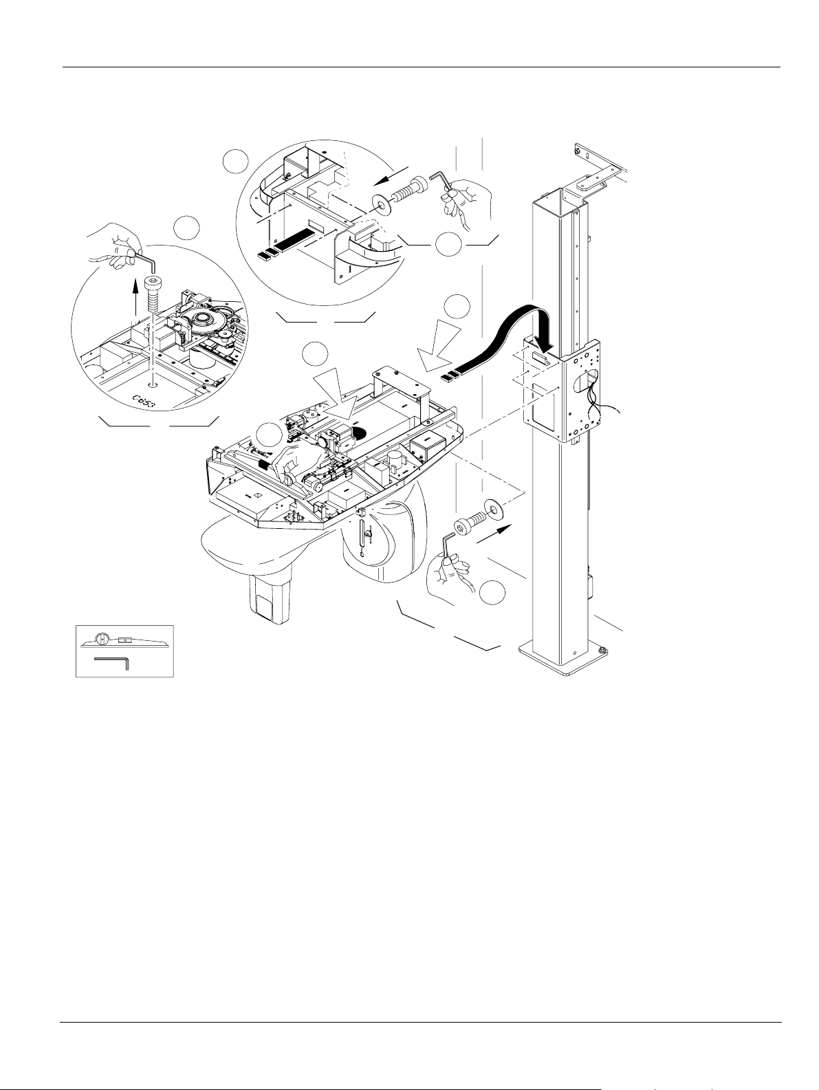
7. With the help of 3 persons, grasp the Unit head, mount and position it on the hook of the column sliding unit (A). Screw, but do not tighten, the 2 upper screws with washers (B).
8. Release the Unit rotating arm by removing the transit locking screw (C) that passes through the CJ 653 board. Place the screw in the chassis, so that it can be retrieved quickly if the Unit is dismantled at a later date.
6–6 INSTALLING THE UNIT
Page 47
Installing the Unit
A
x2
C
B
x1
6 mm
A
7
C
8
E
x2
D
9
9. Rotate the Unit rotating arm by hand. Screw, but do not tighten, the 2 screws with washers located under the Unit head (D).
Relieve the weight of the head at the front with the help of 1 person. Check that the head is
correctly positioned using a spirit level (E). Tighten the 2 upper (B) and the 2 lower (D)
screws with washers of the head assembly.
The column is ready for the fixed arm attachment.
KODAK 9000 3D Extraoral Imaging System_Installation Guide (SM711)_Ed 01 6–
Page 48
Installing the Unit
Installing the Fixed Arm
B
x1
B
A
x4
C
10
6 mm
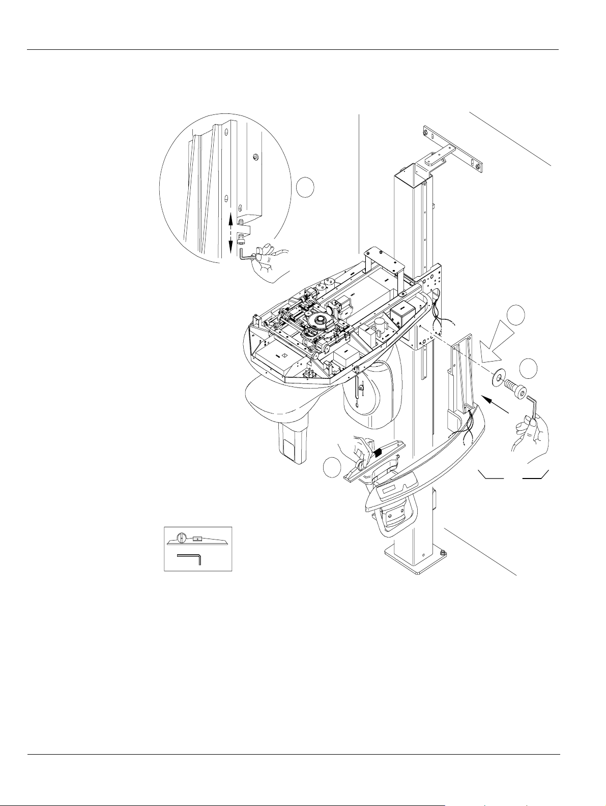
To install the fixed arm, follow these steps:
10. With the help of 2 persons, lift the fixed arm and attach it to the column with 4 screws with
washers (A), but do not tighten. Use the level adjustment screw (B) and the spirit level (C)
to correctly position the fixed arm; then, tighten the 4 screws with washers (A).
6–8 INSTALLING THE UNIT
The Unit is now ready for the general wiring connection.
Page 49
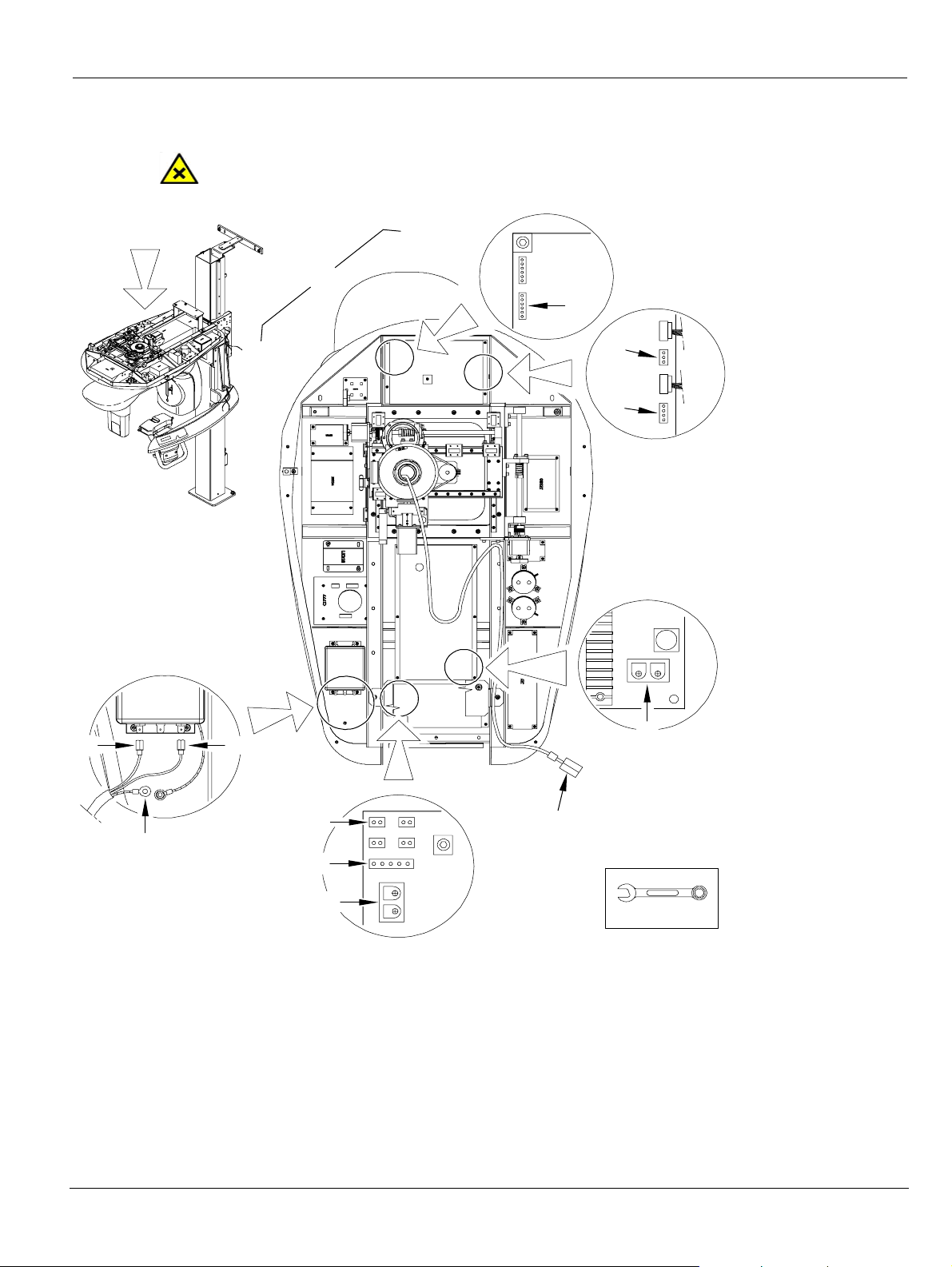
Connecting the General Wiring
CAUTION
Make sure that the circuit breaker of the Unit is switched off.
Installing the Unit
LF440
11
LF440
CJ732
CJ699
CJ653
CJ732
J20
F
J3
H
CJ732
J7
J8
J16
G
J19
CJ653
J9
A
C
B
J7
E
L
J6
J11
J10
J8
K
CJ699
J
J5
To connect the wiring, follow these steps:
11. Connect the following wiring in the indicated order: Connect the cables on the right side of the column to the head in the following order:
• Connect the blue (A) and the brown (B) wires to the line filter input terminals.
• Connect the yellow-green (C) wire (ground) to the ground post on the side of the
KODAK 9000 3D Extraoral Imaging System_Installation Guide (SM711)_Ed 01 6–
D
10 mm
Page 50

Installing the Unit
line filter.
• Connect cable 23 to J9 (D) of the CJ653 board
Connect the cables on the fixed arm to the head in the following order:
• Connect cable 5 to J6 (E) of the CJ699 board.
• Connect cable 1 to J3 (F) of the CJ732 board.
• Connect cable 4 to J19 (G) of the CJ732 board.
Connect the cables on the left side of the column to the head in the following order:
• Connect cable 12 to J8 (H) of the CJ732 board.
• Connect cable 36 to J5 (J) of the CJ699 board.
• Connect the Ethernet cable (K).
• Connect cable 37 to J8 (L) of the CJ699 board.
The Unit is ready for the post-installation control.
6–10 INSTALLING THE UNIT
Page 51
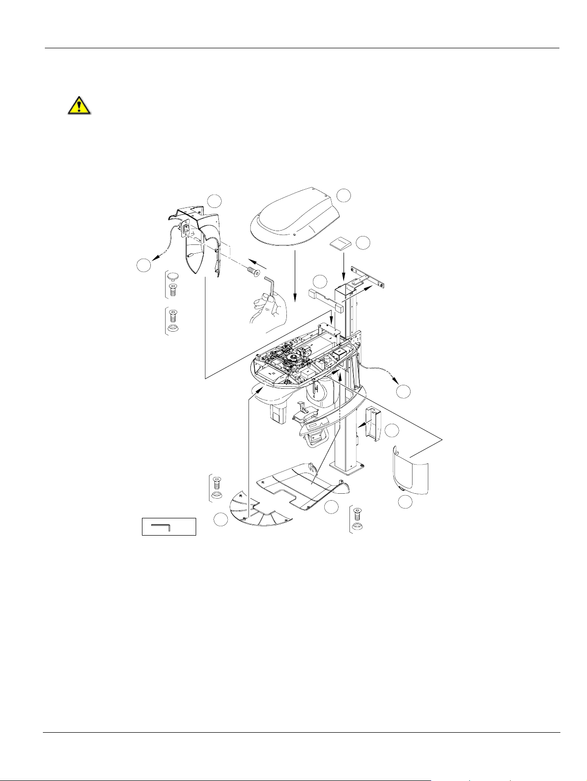
Fitting the Covers
WARNING
Before fitting the covers, you MUST switch off the Unit.
Before fitting the covers check that:
• All the screws in the wall and the floor have been tightened
• All the screws attaching the head and the fixed arm to the column have been tightened
Fitting the Covers
D
1
2 x
4 x
M5x25
M5x50
2 x M5x12
H
A
B
1
C
M5x12
3 x
E
3 mm
F
G
4 x
M5x12
To fit the covers, follow these steps:
1. Fit the upper cover (A) on the column. Fit the cover on the wall-bracket (B). Fit the cover on the column connecting terminal (C) and tighten the 4 screws.
2. Fit the side covers (D) on the column. Position and attach the ON/OFF button to the cover securely with the 2 screws. Fit the cover (E) to the inside of the column. Tighten the screws.
3. Fit the 2 covers (F) and (G) under the head and tighten the screws.
4. Fit the Head cover (H) of the Unit to the head chassis and tighten the 4 screws. You can switch on the Unit now.
KODAK 9000 3D Extraoral Imaging System_Installation Guide (SM711)_Ed 01 6–
Page 52

Fitting the Covers
6–12 INSTALLING THE UNIT
Page 53

Chapter 7
Maintenance
Annual Maintenance
We recommend that a general inspection of the Unit should be carried out every year by an
approved dental systems technician.
The inspection should cover the following points:
• Check the attachment points to the floor and the wall.
• Check all the mobile components of the Unit.
• Check the X-ray generator.
• Check the alignment of the x-ray.
• Make an image acquisition with the test tools and check the image.
• Check the focal trough and the symmetry.
• Check the degree of legibility of the labels.
• Check for damage to cables, covers, oil leaks, etc.
If the results of any of these inspections are unsatisfactory, refer to the Service Manual in order
to rectify any problems.
If there is any doubt, do not operate the Unit.
KODAK 9000 3D Extraoral Imaging System_Installation Guide (SM711)_Ed 01 7–1
Page 54

Annual Maintenance
7–2 Maintenance
Page 55

Chapter 8
TECHNICAL SPECIFICATIONS
Compliance with International Standards
The KODAK 9000 3D digital imaging Unit is compliant with the International and EEC
standards.
Manufacturer
TROPHY
A subsidiary of Carestream Health, Inc.
4, Rue F. Pelloutier, Croissy-Beaubourg
77435 Marne la Vallée Cedex 2, France
Model
KODAK 9000 3D Unit, KODAK 9000 Unit.
Compliance with International Regulations
• Medical Device directives 93/42/ European Economic Community (EEC), Class II b
• ElectroMagnetic Compatibility (EMC) directive 89/336/EEC
Compliance with International Standards
• International Electrotechnical Commission (IEC) 60601-1 Class I Type B
• IEC 60601-1-2, Group I, Class B +12db
• IEC 60601-1-3
• IEC 60601-2-7
• IEC 60601-1-28
Ambient Operating Conditions
• Temperatures: 5 ~35 °C
• Relative humidity: 30 ~ 85%
• Atmospheric pressure: 700 ~ 1060 hpa
Storage Conditions
• Temperatures: -10 ~ 60 °C
• Relative humidity: 10 ~ 95%
• Atmospheric pressure: 700 ~ 1060 hpa
Transport Conditions
• Temperatures: -10 ~ 60 °C
• Relative humidity: 10 ~ 95%
• Atmospheric pressure: 700 ~ 1060 hpa
KODAK 9000 3D Extraoral Imaging System_Installation Guide (SM711)_Ed 01 8–1
Page 56
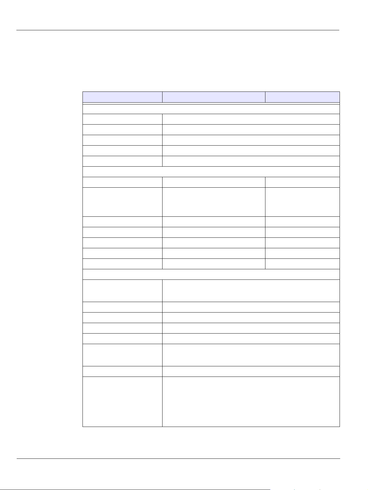
Unit Technical Specifications
Unit Technical Specifications
Table 8-1 describes the technical specifications for the KODAK 9000 3D digital imaging unit
and Kodak 9000 digital imaging unit.
Table 8–1 Unit Technical Specification
Kodak 9000 3D Kodak 9000
X-Ray Generator
Tube voltage 60 - 90 kV (max), pulsed mode for 3D modality
Tube current 2 - 15 mA (max)
Frequency 140 kHz (max)
Tube focal spot 0.5 mm (IEC 60336)
Total filtration > 2.5 mm eq. Al
3D Modality
Technology Digital Volumetric Tomography (DVT) NA
Sensor technology
• CMOS
• Optical fiber sensor with Csi
coating
NA
Gray scale 16384 - 14 bits NA
Volume size 50 x 37 mm NA
Voxel size 76.5 x 76.5 x 76.5 µm NA
Reconstruction time Depends on the PC NA
X-ray pulse time 30 ms
Panoramic Modality
Sensor technology
• CCD
• Optical fiber sensor with Csi coating
Sensor matrix 61 x 1244 pixels
Image field 6.3 x 129.4 mm
Gray scale 16384 - 14 bits
Magnification 1.27
Exposure time
• Adult panoramic 13.9 sec.
• Pediatric panoramic 13.2 sec.
Programs 12 anatomical settings
Radiological exam options
• Panoramic
• Segmented panoramic
• Maxillary sinus
• LATMJ x2
• LA TMJ x4
8–2 TECHNICAL SPECIFICATIONS
Page 57
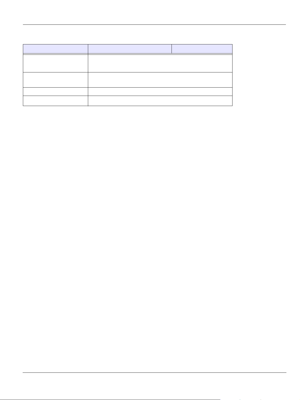
Table 8–1 Unit Technical Specification
Kodak 9000 3D Kodak 9000
Input voltage
• 230 / 240 V - 50/60 Hz
• 100/110/130 V - 50/60 Hz
Unit dimensions 1158mm (L) x 1595mm (D) x 2378mm (H)*
* Unit with shorter column is available on special order
Required space 1500 (L) x 2000 (D) x 2400 (H) mm
Unit Technical Specifications
Weight
160 kg (353 lb
)
KODAK 9000 3D Extraoral Imaging System_Installation Guide (SM711)_Ed 01 8–3
Page 58
Unit Electronic Specifications
Unit Electronic Specifications
Type of Electrical Power Supply
Acceptable fluctuation ± 10% ± 10%
Apparent resistance of the power
supply circuit
Permanent absorbed current 0.45 A 0.9 A
Current absorbed during the x-ray
emission
Maximum absorbed power 2.2 kVA 2.2 kVA
Protection for the power supply
system
Nominal high voltage 90 kV 90 kV
Maximum corresponding tube
current
Nominal tube current 15 mA 15 mA
Maximum corresponding high
voltage
Tube current/voltage combination
for maximum output power
Nominal power for an exposure time
of 0.1 s.
230/240 V (± 10%) 50/60 Hz,
Single-Phase
0.5
(max.) 0.12 (max.)
ΩΩ
9.5 A 22 A
By shutter release at a maximum
current of 16A and a differential
current of 30 mA
10 mA 10 mA
80 kV 68 kV
80 kV, 15 mA 85 kV, 12 mA
at 80 kV, 15 mA: 1200 W at 85 kV, 12 mA: 1020 W
100/110/130V (± 10%) 50/60 Hz,
Single-Phase
By shutter release at a maximum
current of 20A and a differential
current of 30 mA
Utilization Rate in Continuous Mode (for
example: one exposure - 85 kV, 5 mA - 13.9
second, every 3 minutes)
33 W 93 W
Selection of the Load Parameters:
kV (in increments of 1 kV) From 60 to 90 kV
mA (in increments of 25%) From 2 to 15 mA
Cooling Conditions
Maximum dissipation of heat from the x-ray
radiogenic assembly into the ambient air (for
utilization rate in continuous mode)
Accuracy of the Load Parameters
High voltage kV ± 10%
Current in the tube mA ± 20%
Exposure time seconds Seconds ± (10% + 1ms)
Utilization Rate in Intermittent Mode (for example: on e
exposure - 80 kV, 15 mA - 13.9 second, every 3 minutes)
33 W
8–4 TECHNICAL SPECIFICATIONS
Page 59
X-Ray Generator Technical Specifications
Measurement Conditions
kV Indirect on the peak kilovolt meter
mA Direct measurement in the circuit using an oscilloscope
Exposure time Measurement at 75% of the kV values with peak kilovolt meter
X-Ray Generator Technical Specifications
Table 8–2 Filtration of the Material in the X-ray Field
Standard Compliance
IEC 60601.1.3 Compliant
Nominal value of the inherent filtration at 70 kV 2.5 mm (0.10'') eq. Al
Nominal value of the supplementary filtration at 70 kV NA
Nominal value of the total filtration at 70 kV 2.5 mm (0.10'') eq. Al
Filtration value for the enclosure of the x-ray tube (at 100 kV) 0.2 mm (0.008")
Filtration value for the enclosure of the image receiver unit (at 100
kV)
Filtration value for the sensor case 0.8 mm (0.031") eq. Al
0.2 mm (0.008")
The x-ray generator comprises the following:
• A transformer and an x-ray tube and their associated electronic components immersed in oil
• An aluminum filter, which enhances the quality of the beam and reduces the dose received by the patient
• A lead collimator, which limits the size of the beam at the image receiver unit
• A thermal cutout, which trips at an operating temperature between 63 to 70° C ( ± 5° C)
Table 8–3 Technical Specifications of the X-ray Generator
Standard Compliance
IEC Standard 60601.2.28 Compliant
Manufacturer Trophy
Degree of protection against electric shock Class I
Degree of patient protection from the parts applied to the leakage current Type B
Maximum accumulated heat 110 kJ
Maximum continuous heat dissipation 33 W
Tolerances on the position of the focal spot +/- 2.5mm
Radiation leakage after one hour's operation (maximum utilization rate of
93W, i.e. 90 kV, 10 mA, 13.9 sec. every 2 minutes 15 sec.)
< 1 mGy
Weight 8.2 kg
Dimensions 235 x 245 x 120 mm
KODAK 9000 3D Extraoral Imaging System_Installation Guide (SM711)_Ed 01 8–5
Page 60
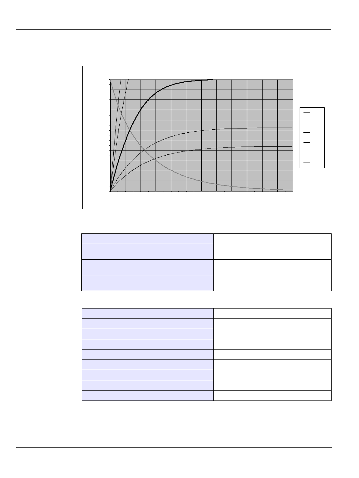
X-Ray Generator Technical Specifications
Figure 8–1 Heating and Cooling Curves of the X-ray Generator.
110,0
100,0
90,0
80,0
70,0
60,0
50,0
40,0
Accumu late d h eat in kJ
30,0
20,0
10,0
0 60 120 180 240 300 360 420 480 540 600 660 720
Time in m in utes
100 W
66 W
33 W
15 W
10 W
Cooling
Table 8–4 Beam Limitations of the X-ray Generator
Manufacturer Trophy
Heating and cooling curves
Type Rigidly mounted unit with fixed window dimensions,
Maximum symmetrical field of radiation at a distance of
613 mm from the focal point (Panoramic mode)
not removable, and integrated x-ray generator
4 (-0.5/+1) x 128 (± 2) mm
Maximum symmetrical field of radiation at a distance of
690 mm from the focal point (3D mode)
Table 8–5 Characteristics of the X-ray Tube
Manufacturer’s n ame CEI
Type OPX 105
Nominal high voltage 90 kV
Nominal anode power 810 W
Maximum amount of heat accumulated in the anode 30 kJ
Nominal focal spot diameter (IEC 60336) 0 .5 mm (0.020'')
Anode materials Tungsten
Target angle 5°
Inherent filtration 0.5 mm (0.20 ") eq. Al
8–6 TECHNICAL SPECIFICATIONS
47 (± 1) x 59 (± 1) mm
Page 61
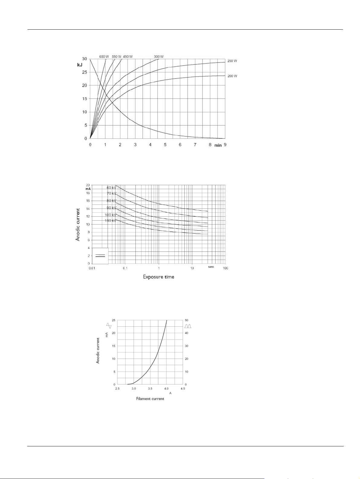
Figure 8–2 Heating and Cooling Curves of the X-ray Tube
Figure 8–3 Single Load Chart of the X-ray Tube
X-Ray Generator Technical Specifications
Figure 8–4 Filament Emissions of the X-ray Tube
KODAK 9000 3D Extraoral Imaging System_Installation Guide (SM711)_Ed 01 8–7
Page 62

X-Ray Generator Technical Specifications
8–8 TECHNICAL SPECIFICATIONS
 Loading...