

Page 1

Infant Flow® LP nCPAP system
Clinical training workbook
Page 2

Table of contents
Infant nasal CPAP ..............................................................................................1– 6
CPAP over view .....................................................................................................1–3
CPAP modalities .......................................................................................................4
Variable flow technology ..........................................................................................5
Self assessment ........................................................................................................6
Infant Flow
Infant Flow LP system ...............................................................................................7
Infant Flow SiPAP configurations ..............................................................................8
Infant Flow SiPAP display screen ............................................................................... 9
Infant Flow CPAP and circuit set-up ........................................................................ 10
Humidification and nCPAP ......................................................................................11
Airway temperature probe placement ................................................................... 11
Infant Flow SiPAP sensor calibration .......................................................................12
Infant Flow SiPAP set-up guide ......................................................................... 13 –14
Respiratory abdominal sensor ................................................................................. 15
Self assessment ......................................................................................................16
Infant Flow SiPAP nCPAP driver ................................................................... 17–22
Modes of operation .......................................................................................... 17–18
BiPhasic mode strategy ..................................................................................... 19 –20
SiPAP exercises and self assessment.................................................................. 21–22
®
SiPAP driver overview ............................................................... 7–16
Infant Flow LP generator assembly ............................................................. 23–27
Infant Flow LP generator ........................................................................................23
Infant Flow LP interfaces ................................................................................... 24–25
Infant Flow LP fixation devices ................................................................................ 26
Self assessment ......................................................................................................27
Infant Flow LP patient set-up...................................................................... 28– 46
Infant Flow LP interfaces ................................................................................... 28 –29
Fixation devices ......................................................................................................30
Headgear application ............................................................................................. 31
Generator assembly preparation .............................................................................32
Generator assembly and interface attachment to headgear ............................. 33–34
Bonnet application .................................................................................................35
Generator assembly and interface attachment to bonnet ................................. 36 –37
Bonnet application (alternative method 1) .............................................................. 38
Bonnet application (alternative method 2) ..............................................................39
Incorrect application of fixation device and generator assembly ....................... 40 – 41
Incorrect application of generator assembly and interface ................................ 42– 43
Final inspection of nasal interface placement .........................................................44
Self assessment and return demonstration ...................................................... 45–46
Routine nCPAP care ....................................................................................... 47– 49
Initiating and maintaining
effective nCPAP therapy
is a critical step in helping
respiratory- compromised
infants achieve successful
recovery and develop
normal respiratory
function. When used
according to your facility’s
treatment protocols and
with this training
workbook, the Infant Flow
LP nCPAP system can
effectively deliver nCPAP
therapy to help improve
patient outcomes.
Frequently asked questions .........................................................................50–54
Self assessment ......................................................................................................54
Glossary ..........................................................................................................55 –56
References ............................................................................................................57
Page 3

Infant nasal CPAP
Introduction
Worldwide each year, approximately 15 million (1 out of every 10) babies are born prematurely.1 Premature or
low-birth weight (LBW) infants are at a high risk for respiratory problems due to underdeveloped lungs. Common
neonatal respiratory conditions include apnea of prematurity, respiratory distress syndrome, transient tachypnea
of the newborn (TTN), meconium aspiration syndrome, pulmonary edema and post-extubation support. These
1,2
conditions are often associated with decreased pulmonary compliance and functional residual capacity (FRC).
Several of these infants will require respiratory support.
Respiratory distress syndrome (RDS) is a condition that strains normal respiration due to the lack of natural
surfactant production. Approximately 50% of neonates born at 26 to 28 weeks gestation and 30% of neonates
born at 30 to 31 weeks gestation develop RDS.
2
CPAP overview
What is surfactant?
Surfactant is a phospholipid, which reduces surface tension
to increase lung compliance.
Artificial surfactant may be given to help reduce surface
tension, increase compliance and improve ventilation.
Without additional respiratory assistance, many infants have
difficulty establishing the adequate functional residual
capacity (FRC) required to maintain normal respiration.
Respiratory support
Several options are available to help the clinician provide
respiratory support to the neonatal patient. Historically, the
initial treatment for infants with respiratory problems was
mechanical ventilation via an artificial airway. Intubation
presents a variety of challenges for any patient but
compounds problems with premature infants. Given the
potential complications of intubation, many physicians opt
for a less invasive approach for spontaneously breathing
infants that utilizes continuous positive airway pressure
(CPAP). As infants are preferential nose-breathers, nasal
CPAP (nCPAP) is the preferred method for treatment
delivery. CPAP enhances alveolar recruitment decreasing
pulmonary vascular resistance and intrapulmonary shunting,
stabilizes FRC and improves oxygenation. By increasing
surface area to alveolar gas exchange, CPAP decreases V/Q
mismatch. The goal of CPAP therapy is to maintain normal
lung volumes and oxygenation, while enabling the infant
3,4
to breathe on their own.
Physiologic effects of CPAP are
represented in the organizational chart on page 2.
1
Page 4

Physiologic effects of nasal CPAP in neonates
3–4,10
Infant nasal CPAP
Splint open airways
Recruits alveoli
and prevents
alveoli collapse
Increases FRC
and lung volumes
Improves V/Q ratio
and increases
oxygenation
Decreases WOB
Nasal (nCPAP) is associated with improved respiratory mechanics and decreased chronic lung disease (CLD) rate.
Conserves
surfactant
Maintains airway
Increases pharyngeal
cross section
patency
Decreases
obstructive apnea
Reduces upper
airway resistance
Stabilizes chest wall
and diaphragm
Improves
breathing pattern
and decreases WOB
Decreases
intrapulmonary
shunting
Improves
V/Q ratio
Stretches lung
Stimulates the
J receptors and HIBR
Reduces central
and
obstructive apnea
and pleura
Stimulates lung
growth
What is nasal CPAP (nCPAP)?
nCPAP is the application of positive pressure to
the airways of a spontaneously breathing infant
throughout the respiratory cycle. nCPAP is a continuous
flow of gas administered through nasal prongs inserted
in the nares or by a nasal mask placed around the
perimeter of the nose. The positive pressure, usually
O to 8 cmH2O, acts as a splint, which can help
4 cmH
2
prevent alveoli collapse.
BiPhasic CPAP alternates between two levels of CPAP
at a set time interval. The infant can breathe at both
CPAP settings. The BiPhasic mode helps increase the
infant’s tidal volume and may stimulate the respiratory
drive center.
2
Advantages of CPAP
• Increases FRC
• Maintains and increases lung volume
• Improves lung compliance
• Reduces work of breathing (WOB) and
airway resistance
• Provides a noninvasive procedure
• Allows small airways to develop
• Promotes the use of natural surfactant
• Promotes easy application
• Provides cost effectiveness
• Helps prevent extubation failure in some infants
• Stabilizes the airway diaphragm and chest wall
• Decreases incidence of chronic lung disease (CLD)
Page 5

Indications for use
2–5
• Abnormalities on physical examination
- Increased WOB
- Increased respiratory rate
- Intercostal and substernal recession
- Grunting and nasal aring
- Pale skin color
- Restlessness
• Deteriorating arterial/capillary blood gas values
(e.g., hypercapnea)
• Increased oxygen requirements to maintain a SaO
greater than 92% with FiO
> 60%
2
• Atelectasis and inltration
• Clinical conditions
- Apnea of prematurity
- Chest infections (e.g., pneumonia)
- Transient tachypnea of the newborn (TTN)
- Mild meconium aspiration
• Weaning/Post-extubation support
• Congenital malformations of the upper airway (cleft
palate, choanal atresia or tracheoesophageal stula)
• Congenital diaphragmatic hernia or untreated
bowel obstruction
• Poor respiratory drive unresponsive to CPAP therapy
(frequent apnea episodes associated with oxygen
desaturation and/or bradycardia)
What is work of breathing?
WOB describes the amount of effort required to breathe.
2
Any therapy that introduces incoming pressure to a
patient’s respiratory system potentially adds imposed
WOB. Infants with RDS experience elevated WOB levels,
and by expending additional effort to inhale and exhale
against pressurized gas, the infant consumes precious
calories overcoming the high WOB level. These calories
could otherwise be spent on vital recovery and growth
processes. In addition to helping the infant conserve energy,
a WOB reduction may reduce stress and anxiety levels.
Contraindications for use
2–5
• Severe cardiovascular instability
• Respiratory failure dened as pH < 7.25 and
> 60 mmHg torr
PaCO
2
Potential problems associated with CPAP therapy
3,5,6
Clinicians should be aware of the possible hazards and
complications associated with CPAP, and take the
necessary precautions to ensure safe and effective
applications, such as:
• Possible loss of prescribed pressure and decreased FiO
2
due to mouth breathing
• Increased intrathoracic pressure reducing venous return,
which may lower cardiac output
• Barotrauma leading to surgical emphysema/
pneumothoraces
• Aspiration
• Deterioration in the respiratory condition, requiring
immediate ventilation
• Patient discomfort from prong/mask intolerance
• Nasal septal injury (e.g., columella necrosis)
• Blanching of the nares
• Dry mouth and airways
• Gastric ination
Columella necrosis
Nasal dilation
3
Page 6
CPAP modalities
What are the treatment options?
A variety of technologies have been employed in nCPAP
delivery throughout the years.
Conventional CPAP (V-CPAP): Utilizes a traditional mechanical
ventilator to deliver a constant flow of gas. CPAP is created
by changing the expiratory port orifice size. The ventilator
equipment is comprehensive and expensive.
Bubble CPAP (B-CPAP): Utilizes a constant flow of heated
and humidified gas. The level of pressure is controlled by
the depth of the exhalation tube inserted into a water
container. The pressure can increase if condensate collects
in the tubing, the flow rate changes or the water evaporates
from the container. B-CPAP lacks system alarms and
imposes a higher WOB
inability to entrain flow during inspiration.
due to the constant flow and
(16 ,18 ,19)
High flow nasal cannula (HFNC): Has not been cleared by
the FDA for nasal CPAP delivery. HFNC utilizes a constant
flow of heated, humidified gas that potentially delivers a
positive distending pressure. The level of therapy cannot
be measured and fluctuates depending on body position,
oral leaks, nasal secretions and the size and weight of the
patient. HFNC does not contain critical alarms that ensure
the safe delivery of therapy.
Variable flow CPAP (VF-CPAP): Incorporates a generator that
redirects the heated and humidified gas flow away from the
patient during exhalation and allows air entrainment during
periods of high inspiratory effort.
provides the most stable pressure, even in the presence of
leaks up to 6 LPM.
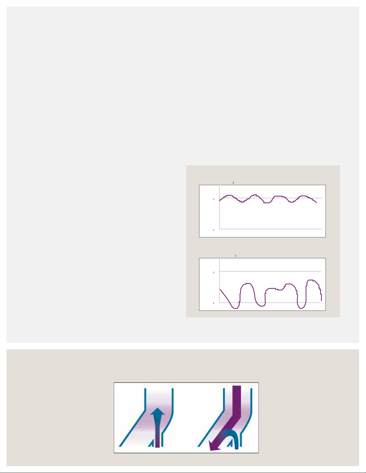
Pandt and Associates demonstrated that the Infant Flow
variable flow technology delivered a consistent level of
CPAP with little fluctuations. In contrast, the conventional
CPAP did not reach the desired level of 5 cmH
O, and
2
the pressure fluctuated significantly throughout the
breath cycle.
9
Using a variable flow generator with a dedicated CPAP
driver provides a measurable therapy with system alarms
to help ensure safe and effective therapy.
Infant Flow
8 Lts flow, 5 cmH2O
System pressure
5 cmH2O
0 cmH
O
2
Time
Conventional CPAP
17 Lts flow, 5 cmH2O with 5 Lts reservoir bag
System pressure
5 cmH2O
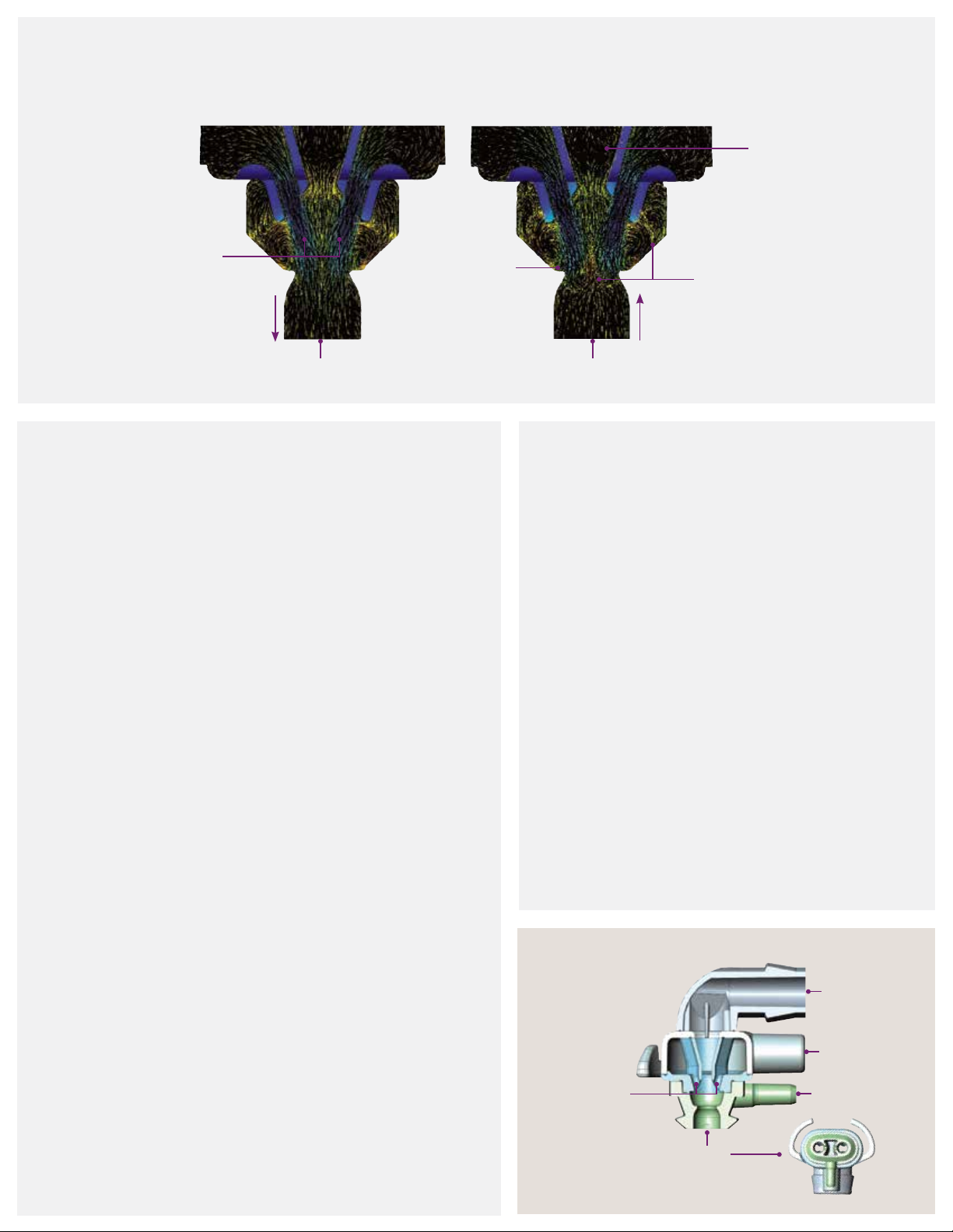
By redirecting the gas, VF-CPAP offers a lower imposed
WOB and less expiratory resistance compared to other
nCPAP technologies. Because the pressure is created and
measured at the nares, the variable flow technology
Infant Flow variable ow
Inspiration: Gas flow converted
to pressure reducing the WOB
and maximizing the pressure
stability at the patient interface.
4
0 cmH
O
2
Moa, G., Nilsson, K. et al. Crit Care Med, 1988 , 16(12):1238 –1242 .
Expiration: Gas flow
flipped away from the nasal
prongs to the expiratory
tube. The residual gas
pressure provided by the
continuous gas flow creates
a stable CPAP throughout
the respiratory cycle.
Time
Page 7
Variable ow technology
Inhalation
Dual jets
Flow direction Flow direction
Patient nare
What is variable ow technology?
10,11
The Infant Flow LP patented dual-jet variable flow
generator utilizes fluidic technology to deliver a
constant CPAP at the airway proximal to the infant’s
nares. Without moving parts or valves, the generator
provides consistent performance. The level of CPAP
created is proportional to the flow provided by the
driver; for example, 9 LPM creates approximately
5 cmH
O CPAP. The variable flow generator uses
2
Bernoulli’s Principle via injector jets directed toward
each nare. If the infant pulls additional flow, the
venturi action of the injector jets entrains additional
flow from either the source gas or exhalation tube
reservoir. During exhalation, the incoming gas flow
redirects away from the infant. This action is referred
to as the “fluidic flip.” By redirecting the gas, variable
flow nCPAP reduces the imposed WOB. The infant
can exhale freely and conserve precious calories for
development. In summary, the direction of gas flow
in variable flow devices depends on the patient’s
respiratory cycle. The flow “flips” away from the
nares when the infant exhales and then, “flips” back
as the exhalation phase ends. The response is almost
instantaneous as it occurs at the patient’s nares.
Fluidic flip
Exhalation
Exhaust tube
Vortice shedding
Patient nare
What is vortices technology?
10,12
The patented Infant Flow LP generator is a new form of
variable ow that uses vortices technology to reduce the
imposed WOB during inhalation. Similar to the single- jet
technology, the ow entrainment reduces the WOB
on inhalation by meeting the patient’s inspiratory ow
demand and during exhalation gas ow ips away from
the patient reducing resistance.
Four low-momentum jets (two per nare) impinge inside
the generator to create a consistent and measurable
positive airway pressure within the generator head.
During inhalation, the dual jets entrain ow to meet
the patient’s inspiratory demand. During exhalation, the
jets easily deect to disrupt the gas ow. This disruption
of ow creates vortice shedding that spirals outwardly,
combining with the exhaled breath to create an
organized, efcient ow path toward the exhaust ports.
Exhaust
tube
Impinging
jets
Drive
line
Pressure
line
Patient
5
Page 8

Self assessment
1. Describe RDS:
2. List three indications for nCPAP therapy:
3. List three benets of nCPAP therapy:
4. List three potential complications to nCPAP therapy:
8. Match the generator parts to the diagram:
Pressure line
Impinging jets
Exhaust tube
Drive line
Patient
c
d
b
a
e
Notes:
5. State four methods used to deliver nCPAP therapy:
6. Discuss the advantage of variable ow technology compared
to other CPAP modalities:
7. Discuss the importance of low work of breathing:
6
Page 9
Infant Flow SiPAP
driver overview
Infant Flow LP system
The Infant Flow LP nCPAP system is a comprehensive system for delivering unique nCPAP therapy.
The system consists of:
• Infant Flow SiPAP driver
• Infant Flow LP generator assembly
• Infant Flow LP fixation—bonnet or headgear
• Infant Flow LP nasal interfaces—mask or prongs
This chapter discusses the set-up and operation of the Infant Flow SiPAP Plus driver.
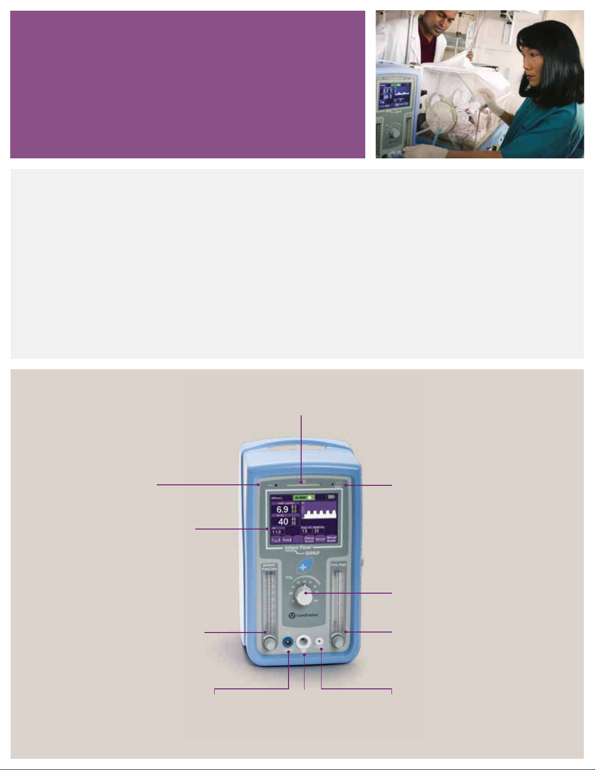
Power LED
Indicates power on
and AC connection
Touch screen display
Adjusts settings and
displays patient parameters
and alarms.
Pressure low flow meter
Adjusts low CPAP level.
CPAP supplied to patient
directly relates to flow rate
from the nCPAP driver.
Alarm LED
Indicates alarm situation as visual and
audible notification color varies according
to alarm level
Note: Refer to the Infant Flow SiPAP
operator manual for additional instructions
on the set-up, operation and maintenance
of the Infant Flow SiPAP Plus driver.
Transducer LED
Indicates
transducer
connected.
% O
blender control
2
Adjusts FiO
Pressure high flow meter
Adjusts high CPAP level. CPAP
supplied to patient directly relates
to flow rate from nCPAP driver.
2.
Transducer
connection
Connects to
transducer interface.
Patient circuit
connection
Connects patient
breathing circuit to
gas outlet port.
Pressure line
connection
Connects patient
pressure line to device.
7
Page 10

Infant Flow SiPAP congurations
The Infant Flow SiPAP driver is sold globally and is available
in different configurations. The two main models are Infant
Flow SiPAP Plus and Infant Flow SiPAP Comprehensive.
The Comprehensive model offers an additional ventilation
mode, BiPhasic trigger, which is not available in the U.S.
In select areas, additional languages or an international icon
overlay may be used in place of the English text. The operation
and maintenance of the Infant Flow SiPAP driver is the
same regardless of the specific configurations. Refer to the
Infant Flow SiPAP operator manual for more specific details.
Description English text ICON symbol
Press to access the user calibration menu and language options.*
Press to return to the start-up screen.
Press to switch between the graphical and numerical monitoring screen.
Press to change the operation mode.
Press to deliver a manual breath. The breath delivers at the pressure high setting for
the set time high duration.
Indicates user should refer to the operator manual for additional information.
Indicates battery status and turns red if the battery charge is less than 40%.
Indicates the screen is locked. Press to unlock the screen.
Adjust the low flow rate setting for the baseline CPAP level.
Adjust the high flow rate setting for BiPhasic high CPAP level.
*Language option not available on all SiPAP models.
8
Page 11
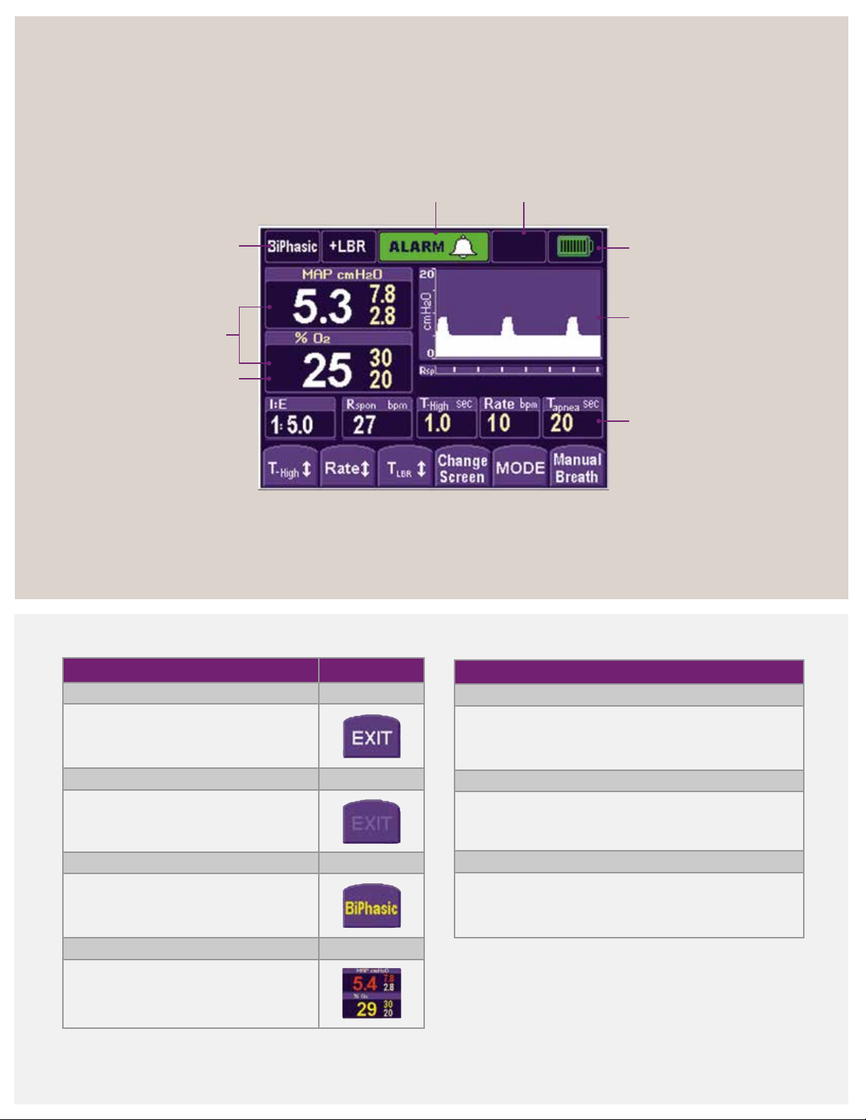
Infant Flow SiPAP display screen
Mode, control settings and function buttons
Mode
indicator
Monitored
parameters
FiO
Alarm priority/alarm
silence indicator
2
Operational
information
Battery
charge
Pressure/ Time graphics
or monitored
parameters display
Control/Setting
indicators
Soft key color code
White letter
Key enabled
Faded letter
Key inactive
Yellow letter
Solid: Pending confirmation
Flashing: Low-priority alarm
Red letter
Flashing: High-priority alarm
Solid: Reduction in another parameter
caused by an adjustment
Alarm management
High priority
• Series of 10 tones sound every 10 seconds
• Parameters display, and limits flash red
Medium priority
• 3 audible tones sound every 15 seconds
• Parameters display, and limits flash yellow
Low priority
• 2 audible tones sound every 30 seconds
• Parameters display, and limits change to yellow
9
Page 12
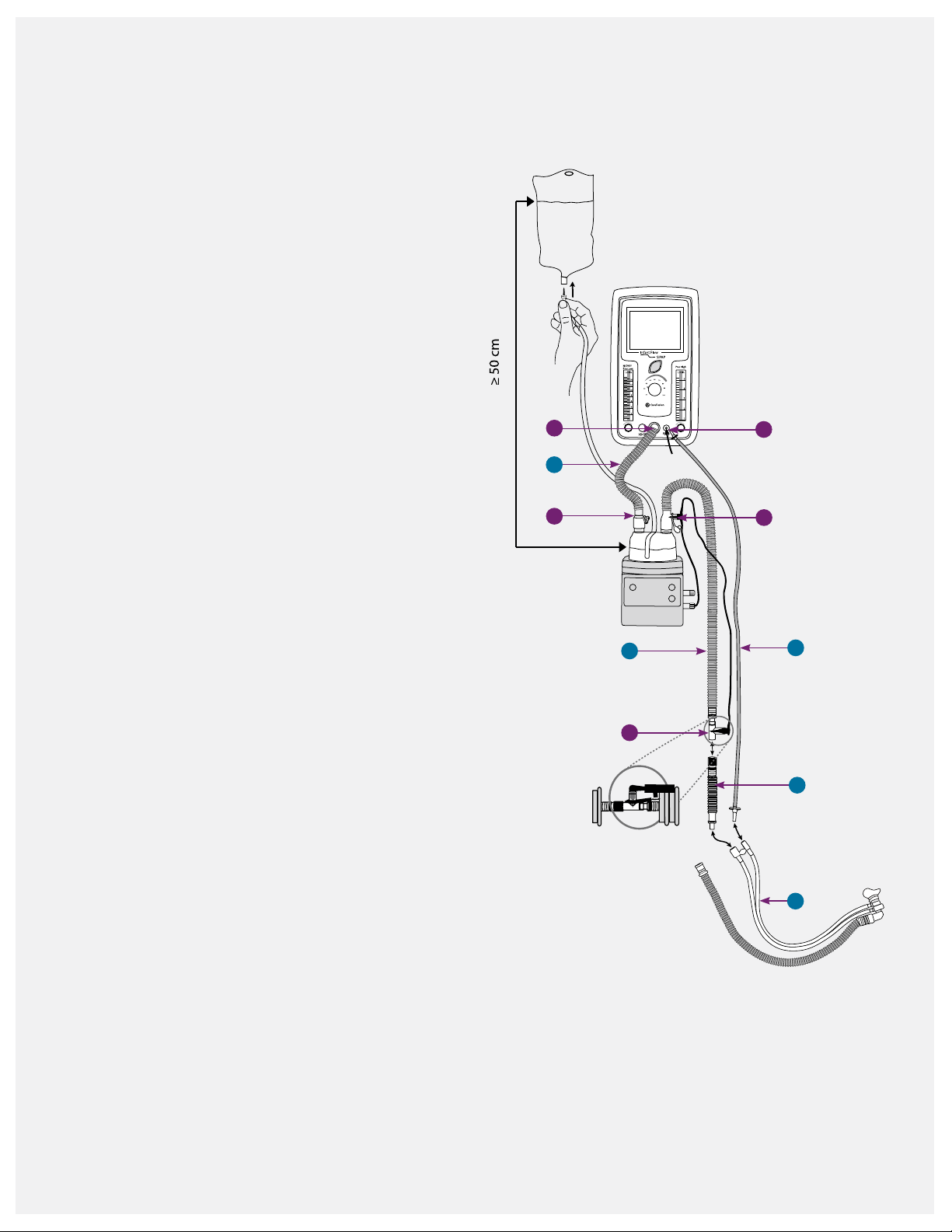
Infant Flow SiPAP and circuit set-up
Circuit set-up
1. Gather the nCPAP supplies:
• Infant Flow SiPAP driver
• Single-limb, heated breathing circuit
• Infant Flow LP generator kit
• Infant Flow LP xation device
• Humidier and chamber
• Sterile water bag
2. Attach the water chamber to the humidier and
connect it to the water feed system. Follow the
manufacturer instructions for the proper set-up.
3. Connect the gas delivery tubing (A) to the ow
driver outlet port (I) and humidier chamber port (II).
4. Connect the elbow connector on the heated
breathing circuit (B) to the humidier chamber.
Insert the heater wire plug into the wire socket.
Securely insert the temperature probe in the port on
the circuit elbow (III). Insert the second temperature
probe (IV) into the airway port at the distal end of
the breathing circuit.
5. Connect the non-heated section (C) to the drive line
of the generator assembly (D).
I
A
II
B
V
III
E
6. Connect the proximal pressure line (E) to the
proximal port on the driver (V) and the pressure
line on the generator.
Temperature probe
When inserting the temperature probe into the
circuit, ensure the probe tip is in the middle of the
gas stream. This allows the gas temperature to be
measured accurately. If the probe is not properly
seated, the temperature measurement accuracy may
be compromised, leading to excessive condensation.
Cover the temperature probe with a reective shield
when used under a radiant warmer or bilirubin light.
IV
C
D
10
Page 13
Humidication and nCPAP
Humidication
Heated humidification is recommended for nCPAP therapy.
The normal functions of the nose and air passages of
the respiratory tract are too warm, moisten and filter
the inhaled gases before they reach the lungs. In normal
respiration, the nasal mucosa and upper airways provide
75% of the heat and moisture supplied to the smaller
airways and alveoli. By the time air reaches the alveoli,
the inspired gas warms to 37 °C at 100% relative humidity
13
With nCPAP, the upper airways are not bypassed,
(RH).
but the high gas flows may be drying to the airways,
especially to a neonate’s underdeveloped lung. Adequate
humidification is essential to maintain airway clearance,
optimize ventilation and improve patient comfort.
The International Organization for Standardization (ISO) and
American Association for Respiratory Care (AARC) clinical
practice guidelines recommend gas temperature
between 34 and 41 °C to provide a humidity level of
33 to 44 mgH
O/L with artificial airways.14 Be cautious
2
using higher temperatures, as condensation may reduce
the mucous viscosity and interfere with the mucous
clearance. Extended exposure of gas temperatures over
41 °C may cause cellular damage to the airways.
14
The higher temperature settings may not be required to
deliver adequate humidification, since an artificial airway
is not used with nCPAP. Start with a temperature setting
of 36 °C to 37 °C and adjust the humidifier settings to
maintain adequate humidification; if condensate occurs,
reduce the humidifier temperature setting.
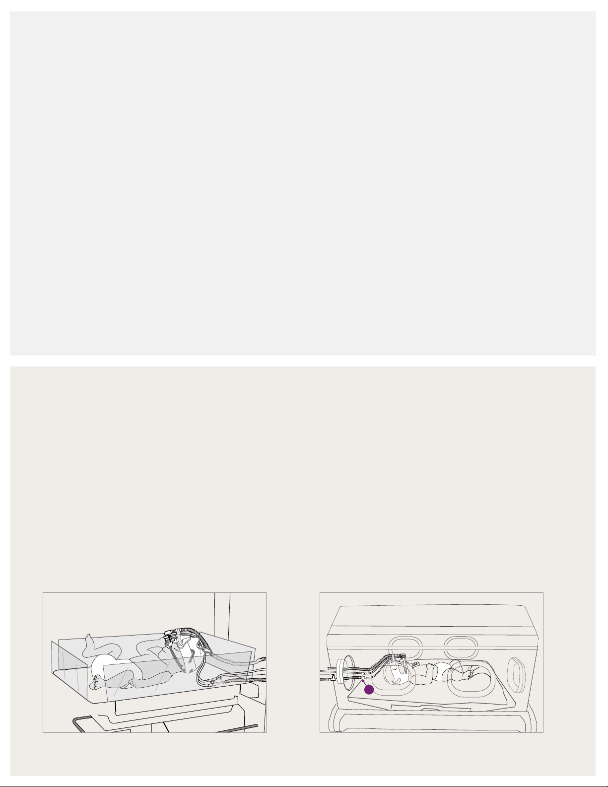
Airway temperature probe placement
Open bed or crib
When the infant is placed on an open bed warmer or
crib, it is recommended to remove the unheated section.
This places the temperature probe next to the
generator assembly.
If the infant is under a radiant warmer or bilirubin light,
the temperature probe should be covered with a light
reflective shield to prevent heating the probe. If the probe
is not covered, it could interfere with the operation of the
humidifier and cause excessive condensation to form.
Isolette or incubator
When the infant is in an isolette or incubator, the
non-heated section should be used with the temperature
probe placed outside of the isolette. Make sure that the
rest of the unheated section remains in the isolette.
If condensation is observed, remove the non-
heated (A) section and place the temperature probe
inside the isolette.
A
11
Page 14
Infant Flow SiPAP sensor calibration
Infant Flow
SiPAP
Pres High
NCPAP/
Pres Low
5
L/min
70
60
50
L/min
14
Infant Flow
SiPAP
Pres High
NCPAP/
Pres Low
L/min
L/min
8
Infant Flow
SiPAP
Pres High
NCPAP/
Pres Low
L/min
L/min
8
100
90
Infant Flow
SiPAP
Pres High
NCPAP/
Pres Low
4
5
L/min
80
70
60
50
40
30
21
L/min
8
10
12
14
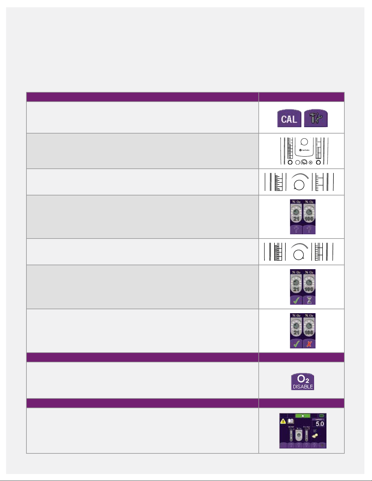
Two-point oxygen sensor calibration
Two-point oxygen sensor calibration should be performed
before initially using the Infant Flow SiPAP driver and with
each circuit change. To avoid unwanted alarms, occlude the
9 LPM prior to turning on the Infant Flow SiPAP driver on.
When the Infant Flow SiPAP driver is turned on, a power on
self-check automatically performs.
prongs or mask and set the low pressure flowmeter to
To perform two-point calibration:
1. Press the CAL button to enter the calibration menu.
2. Set the pressure low flowmeter to 9 LPM and the pressure high flowmeter to 2 to
3 LPM. Note: The pressure high flowmeter must be set during set-up to enable the
manual breath button.
3. Adjust the oxygen control to 21%. Allow time for the reading in the oxygen display
window to stabilize.
4. Press the flashing question mark button located under the 21% icon. The question
mark changes to a static hourglass. When calibration is complete, a static green
check mark icon appears and the oxygen display window reads 21%.
40
80
12
10
14
12
30
10
90
30
21
8
6
4
2
60
50
40
21
4
100
3
2
1
70
5
80
90
4
100
5. Adjust the oxygen control to 100%. Allow time for the reading in the oxygen display
window to stabilize.
6. Press the flashing question mark button located under the 100% icon. The question
mark changes to a static hourglass icon. When calibration is complete, the hourglass
icon changes to a static checkmark. The oxygen display window
reads 100%.
7. If oxygen calibration fails, a red X displays on the button of the screen, the alarm
sounds and an Error code displays on the top-left corner. Turn the driver off and
then, back on. Repeat the calibration procedure.
Disable the oxygen sensor
The internal oxygen sensor may be disabled by pressing the O2 disable button on the
calibration screen. This disables oxygen monitoring and the audible oxygen alarm. An
error code displays to indicate the oxygen monitor is inoperative. An external oxygen
monitor must be used whenever the oxygen sensor is disabled.
Leak test
While occluding the patient interface, set a flow of 9 LPM on the pressure low flowmeter.
A CPAP of 5 cmH
O ± 1 should display on the SiPAP screen. If pressure is not reached,
2
check the system for leaks. Release the occlusion, and the displayed pressure should be
≤ 2 cmH
does not fall, check the circuit for occlusions.
12
O. Wait for 15 seconds, and a disconnect alarm should sound. If the pressure
2
14
12
10
60
50
70
40
30
21
5
80
90
4
100
Page 15
Infant Flow SiPAP set-up guide
Set-up menu screen
1. Adjust the pressure low flowmeter until the desired
nCPAP pressure displays on the screen. Press the flashing
question mark icon, which changes to a static checkmark
to confirm the setting.
2. Adjust the oxygen control dial to set the desire FiO
2
Press the flashing question mark icon. A checkmark
appears to confirm the setting.
3. Adjust the pressure high flowmeter until the pressure
displays 2 to 3 cmH
O above the set nCPAP pressure.
2
Press the flashing question mark icon. A static checkmark
appears to confirm the setting.
4. To use the low breathing rate/apnea monitor, connect
the transducer interface to the Infant Flow SiPAP driver.
Press the flashing question mark under the infant
respiratory sensor icon. This will change to a static
checkmark to confirm the setting. This does not confirm
that you want to use the respiratory monitoring option
but ensures that all modes are available for later use.
%.
Alarm set/conrm screen
Press the nCPAP button or alarm bar for three seconds
to set the alarm limits and move to the next screen. If no
button is pressed within two minutes, the alarm limits
automatically set and the screen changes to the mode
select screen.
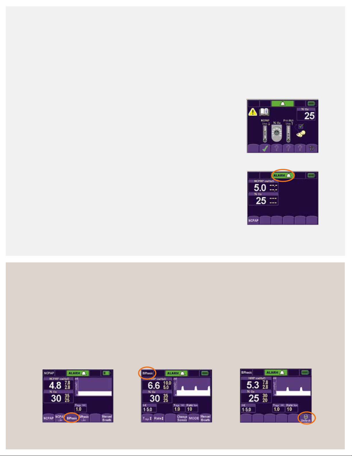
Set-up menu screen
5. After completing the above steps, the screen changes
and displays the nCPAP mode. The infant can now be
connected to the Infant Flow SiPAP system.
Mode select screen
All available modes display at the bottom of the screen.
1. For low breath rate/apnea modes, attach the abdominal
respiratory sensor to the transducer and properly place
it on the infant’s abdomen.
2. Select the desired mode of operation by pressing the
corresponding button (mode select screen). The parameter
adjust screen displays, and the new mode displays in the
upper-left corner (parameter adjust screen).
Alarm set/confirm screen
3. Make the desired setting changes, and press the
selected mode to confirm the settings and activate
the new mode.
4. If no selection is made within two minutes and no
alarms sound, the screen locks to prevent entries. The
mode buttons go blank, except for the last button on
the right (locked screen). To unlock the screen, press
the lock icon.
Mode select screen
Parameter adjust screen
Locked screen
13
Page 16
Infant Flow SiPAP set-up guide (continued)
18.0
16.0
Pressure (cmH
O)
Flow (LPM)
Parameter adjust screen
1. To change the settings during set-up and normal
operation, touch the desired parameter button.
2. Press the up or down arrows to adjust the parameter
to the desired setting.
3. Confirm the change by re-pressing the parameter button.
The main screen displays.
Note: nCPAP and BiPhasic pressure levels are set by
adjusting the flow.
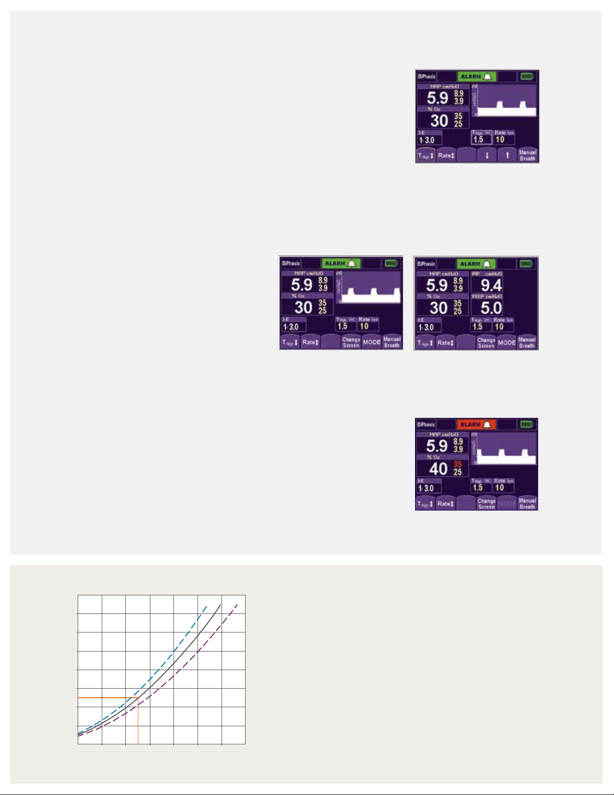
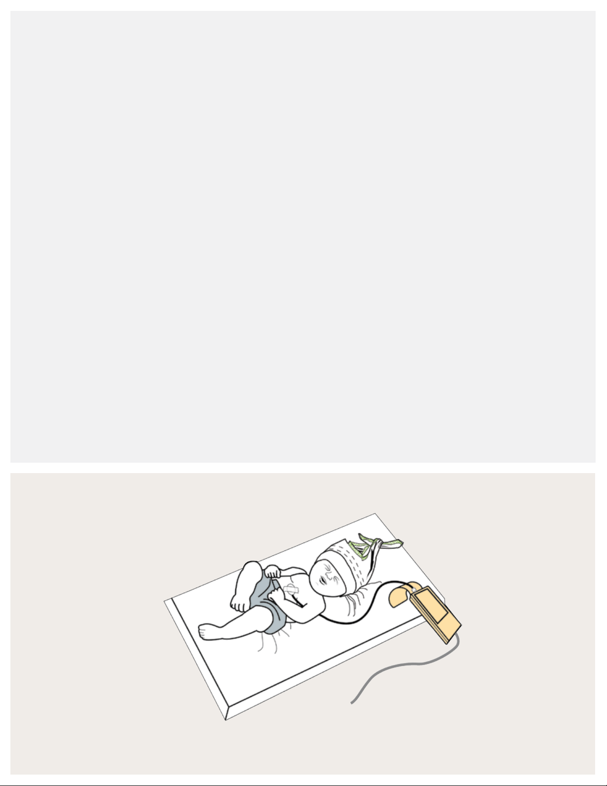
Main screen and monitored parameter screen
1. To monitor therapy, use the main screen or
monitored parameter screen. The main screen
graphically displays the delivered pressure. The
monitored parameter screen displays numerical
values for the delivered pressure.
Parameter adjust screen
14
2. Press the Change Screen button to switch the
screen display.
Alarm reset/silence
1. Press the alarm bar to silence the active alarms
for 30 seconds.
2. Press the alarm bar for three seconds to clear resolved
and low-priority alarms and to reset alarm limits. Smart
alarm technology automatically sets high pressure, low
pressure and % oxygen thresholds.
14.0
12.0
10.0
2
8.0
6.0
4.0
2.0
4.0 6.0 8.0 10.0 12.0 14.0 16.0
Main screen
Monitor parameter screen
Main screen with active alarm
Flow pressure nomogram
The Infant Flow SiPAP LP system is subject to a direct
relationship between the controlled gas flow and airway
pressure. For example, 9 LPM of gas flow provides
approximately 5 cmH
O CPAP.
2
Tip: Manual breath: The high pressure flowmeter must be
set to deliver a manual sigh/breath during CPAP. The boost
in pressure delivers for the time high that was entered during
the set-up process.
Page 17
Respiratory abdominal sensor
Respiratory abdominal sensor (optional)
For use only with the Infant Flow SiPAP Plus and
Comprehensive nCPAP drivers. The respiratory abdominal
sensor enables the clinician to monitor for apnea/low breath
rate in both nCPAP and BiPhasic modes. The accessories
include the reusable transducer and single-patient-use
abdominal sensor. In the BiPhasic trigger mode, the
respiratory abdominal sensor and transducer allow
patient-triggered pressure assists with breath rate
monitoring (not available in the U.S.).
Respiratory transducer connection
1. Connect the transducer cable to the transducer port
on the front panel.
2. Connect the abdominal sensor pressure line to the
transducer interface.
3. Compress the sensor pad gently, repeating this several
times while observing the transducer LED.
Infant set-up
To apply the sensor to the infant using suitable tape
(figure 1):
1. Visually identify the optimum outward movement of
the abdomen during inspiration. When the infant
breathes, the most movement is between the lowest
rib and the abdomen.
2. If the infant is supine, place the capsule midway
between the umbilicus and xiphisternum, which is the
notch at the center of the two lower ribs. On larger
infants, an alternative site is the upper chest to detect
intercostal movement.
3. If the infant is prone, place the sensor laterally over the
lower rib and abdomen. The sensor tubing should be
directed over the back.
4. Tape the sensor firmly into position using a non-
allergenic microprobe tape. Position the sensor line
perpendicular to the tape. Only use tape that is
approved by your facility’s protocol.
5. Verify correct placement. The transducer LED should
illuminate on expiration, and the SiPAP front panel LED
on inspiration.
6. If the LED does not illuminate, try repositioning the
sensor and adding a second piece of tape making an
“X” over the sensor.
Figure 1: Abdominal sensor placement
15
Page 18

Self assessment
1. Where should the circuit airway temperature probe be
placed if the infant is in an isolette/incubator?
2. If condensation occurs in the breathing circuit, what
should you do?
3. Explain how to disable the oxygen sensor:
4. Demonstrate how to reset the alarm limits when the
device is in operation:
7. While in nCPAP, you press the manual breath button,
but nothing happens. What would prevent a manual
breath from being delivered?
8. When should you perform an oxygen sensor
calibration on the Infant Flow SiPAP?
Notes:
5. To deliver a CPAP of 5 cmH
6. Where is the best placement for the respiratory
abdominal sensor?
16
O, what would the ow rate be?
2
Page 19

Infant Flow SiPAP nCPAP driver
Seconds
6
5
4
3
2
1
0
cmH
2
O
81
Volume change (ml/kg)
Modes of operation
nCPAP mode
nCPAP mode delivers constant, stable positive pressure
to infant airways to help restore the FRC in assisting the
correction of hypoxemia. Adjust the flow rate setting to
deliver CPAP up to 11 cmH
O.
2
CPAP parameters:
• CPAP pressure (set by low pressure flowmeter)
• Oxygen percentage
Initial settings:
• CPAP 4 to 6 cmH
O
2
nCPAP + low breath rate (LBR)/Apnea
The mode allows the delivery of CPAP pressures up to
11 c m H
O and breath rate monitoring via respiratory
2
abdominal sensor and transducer interface. For the SiPAP
Plus system, the LBR setting is determined by LBR time (TLBR)
setting from 10 to 30 seconds. For the SiPAP Comprehensive
system, the Apnea setting is determined by the apnea time
(T-apnea) setting from 10 to 30 seconds. If the apnea alarm
is triggered, the device delivers one breath at the high
pressure setting. The high pressure flowmeter must be set.
BiPhasic mode
be set for a duration of 0.1 to 3 seconds to produce
a “sigh.”
Note: This is not the same as pressure support. In
pressure support, the pre-set pressure supports the
inspiratory effort and the patient’s breathing pattern
determines the inspiratory time. In the BiPhasic mode, the
infant can breathe spontaneously at either pressure level.
The time high setting determines the cycle time between
the two levels of CPAP.
BiPhasic parameters:
• Baseline CPAP (set by low pressure flowmeter)
• High CPAP (set by high pressure flowmeter)
• Time high (T-high)
• Rate (cycle rate between pressures)
• Oxygen percentage
Initial settings based on respiratory conditions:
9
• Baseline CPAP 4 to 6 cmH2O
• Pressure high (PHigh) 1 to 3 cmH
O above CPAP level
2
• T-high 1.0 sec
This mode cycles between high/low CPAP levels on a timed
basis. Small incremental pressure increases of 2 to 3 cmH
above CPAP creates a “sigh” breath, and augments FRC
and decreases WOB. The switch to the high CPAP level can
6
5
4
O
2
3
cmH
2
1
0
Seconds
• Rate 6 cycles/minute
O
2
16
12
8
4
0
0246
CPAP pressure
5.5 ml/kg
In this study, a
O shift in
3 cmH
2
pressure on an
average increased
FRC by 5.5 mL/kg.
Pandit, P. Pediatric,
2001, 108(3):682–685.
0
17
Page 20

BiPhasic + LBR/apnea mode
12
16
8
4
0
0246810
CPAP pressure
Volume change (ml/kg)
5.5 ml/kg
This mode is the application of BiPhasic therapy with low
breath rate detection via the respiratory abdominal sensor
and transducer interface. For SiPAP Plus, the LBR setting is
determined by the TLBR setting from 10 to 30 seconds. For
SiPAP Comprehensive, the Apnea setting is determined by
T-apnea setting from 10 to 30 seconds.
SiPAP Comprehensive BiPhasic tr* mode
This mode utilizes the respiratory abdominal sensor and
transducer interface to synchronize pressure high breaths
with the infant’s respiratory efforts. It allows patient-
triggered pressure assists with breath rate monitoring
enabled, adjustable apnea time interval, apnea alarm and
adjustable apnea backup rate. The upper level pressure
delivers based on operator set T-high and PHigh flow rate
settings. The maximum pressure setting is 15 cmH
O. If the
2
respiratory efforts are not detected, the infant receives the
low CPAP setting and the apnea alarm initiates the delivery
of the set backup rate.
BiPhasic tr parameters:
• Baseline CPAP (set by low pressure flowmeter)
• Peak inspiratory pressure (PIP) (set by high
pressure flowmeter)
• T- high
• Backup respiratory rate
• Apnea time
• Oxygen percentage
Initial settings: Initial settings should be tailored to the
infant’s respiratory condition.
• Baseline CPAP at clinical indicated level (4 to 6 cmH
• PIP: 2 to 3 cmH
O above set CPAP level. Set by the
2
O)
2
PHigh flowmeter.
• T-high: ≤ 0.3
Timed BiPhasic breaths are given at the set backup rate, PHigh
and T-high. If the infant triggers within the next time-out
period, the alarm silences and triggered-BiPhasic resumes.
If no breaths are detected after the next apnea timeout,
the audible alarm resumes until the operator intervenes.
10
Ti = 0.2 s
9
8
O)
7
2
6
5
4
3
Pressure (cmH
2
1
0
01
2
3
4
Time (s)
*BiPhasic tr mode available in comprehensive
configurations only. Not available in the U.S.
5
• Rate (Rb): Set rate is active only if Tapnea (sec) threshold
is surpassed. Generally, set it close to the infant’s own
respiratory rate.
• Apnea time (tapnea): 10 to 30 seconds. The apnea
alarm triggers when no breaths are detected within
the selected apnea timeout.
18
Page 21

BiPhasic mode strategy
SiPAP settings
SiPAP is a strategy that assists infants who are spontaneously
breathing yet require some assistance. The theoretical
benefits of the SiPAP strategy are that the sigh cycles may
recruit unstable alveoli (or prevent their collapse), offload
the respiratory work, stimulate the surfactant release and
stimulate the respiratory center drive.
The BiPhasic mode parameters may change depending on
the infant’s respiratory status and condition.
After initiating the therapy, monitor the infant’s oxygen and
ventilation status. Adjust the settings to provide necessary
respiratory support as the infant’s condition changes.
Strategy to improve oxygenation
• Increase CPAP low level
Increases FRC
°
• Increase duration T-high (maximum setting is
three seconds)
Improves alveolar recruitment
°
• Increase FiO
2
Strategy to improve ventilation and oxygenation
• Increase Delta P between CPAP and PHigh CPAP
(#PHigh), which:
Augments tidal volumes
°
Ofoads more WOB
°
• Increase rate, which:
Increases alveolar recruitment and ventilation
°
Ofoads WOB
°
Decreases PaCO
°
2
Signs of positive response to nCPAP therapy
• Reduction in respiratory rate
• Stabilization or reduction in FiO
2
• Resolution of grunting
• Reduction in the degree of sternal and intercostal
recession
• Relaxation, not in opposition to therapy
Tip: Disconnect alarm: A minimum CPAP setting of
3.0 cmH
O is required to detect patient disconnect.
2
Tip: Baseline CPAP: Gas trapping may occur with
inverse I:E ratio. Ensure a one-second minimum at
the baseline CPAP.
Tip: Setting time high (T-high): The SiPAP flow system
delivers a slow rise to the high pressure. If the T-high
setting is too short, the high CPAP may not be reached.
Consider increasing the T-high setting until the high
CPAP level is obtained.
Decreases PaCO
°
2
S. Courtney, MD, Neonatal and Perinatal Medicine, has suggested the protocol below for the application of SiPAP
15
therapy.
Apnea 4–5 cmH
Oxygenation 4–5 cmH
Ventilation 4–5 cmH
BiPhasic mode settings
This information is provided only as a guideline; refer to your facilities policies and procedures for nCPAP.
Low CPAP
2
2
2
O 1–2 cmH2O 0.3–0.5 sec 10 cycles/min
O 2–3 cmH2O 1.0 sec 20 cycles/min
O
High CPAP
(above low CPAP)
≥
3 cmH2O 0.5–3.0 sec 10–30 cycles /min
Time high Cycle rate
19
Page 22

BiPhasic mode strategy (continued)
Indications of failure to nCPAP therapy
3–6
Strategy for weaning
• Ensure FiO
requirements are less than 50%
2
• Slowly decrease the cycle rate
Example: 20–15; 10–5
• Decrease the high CPAP to baseline CPAP
• Continue to monitor the infant’s respiratory status
and wean the infant from CPAP support as tolerated
• FiO2 ≥ 50%
• Respiratory acidosis indicated by a pH < 7.28 and paCO
> 50mm Hg
• Development of recurrent apnea requiring stimulation
• Development of a pneumothorax
• Worsening sternal and intercostal recession/
grunt/tachypnea
• Agitation not relieved by simple measures such
as comforting or light sedation
• Development of spontaneous episodes of signicant
desaturation (< 90% for > 20 sec)
2
History fun facts
• 2698-2699 BC: Huang-Ti, emperor, recorded sudden
death from respiratory failure in neonates. He noted
deaths to be more common in premature infants.
• 1543: Andreas Vesalius, father of ventilation, described
tracheostomy, intubation and ventilation to maintain life.
• 1879: Gairal, French obstetrician, created the aerophore
pulmonaire for intermittent positive-pressure ventilation
of infants.
• 1896: Joseph De Lee described warning signs of
fetal distress, recommending to “supply air to lungs
for oxygenation.”
• 1914: A. Von Reuss described using CPAP to
resuscitate newborn infants with an oxygen tank,
mask and water bottle.
• 1963: H. Barrie described a “bubble” pressure apparatus
with tubing inserted to 40 to 50 cmH
• 1971: George Gregory delivered CPAP via an
endotracheal tube (ET tube) to treat spontaneously
breathing neonates with RDS.
• 1975: Kattwinkel delivered CPAP using binasal prongs.
O.
2
CareFusion history
• 1988: Moa and Nilsson introduced the single-jet
variable ow nCPAP using uidics via a generator
and binasal prongs.
• 1991: The rst commercial Infant Flow generator
was released.
• 1993: The rst EME Infant Flow nCPAP driver
was introduced.
• 2000: The Infant Flow Advance with a BiPhasic trigger
mode was launched.
• 2001: The swivel connector was added to the Infant Flow
generator, and the bonnet design was changed.
• 2004: The Infant Flow SiPAP driver with Simple Touch
operation and advance patient monitoring were introduced.
®
• 2006: The AirLife
nCPAP dual-jet variable ow generator
with headgear and antomically designed interfaces were
introduced in the U.S.
• 2011: The Infant Flow low pressure generator was
launched globally.
20
Page 23

SiPAP exercises and
self assessment
Exercise No. 1
Attach the SiPAP circuit, and occlude the nasal prongs. Enter these settings on the SiPAP driver:
• Set low pressure ow rate at 9 LPM • Set FiO
• Set high pressure ow rate at 2 LPM • Go to nCPAP mode screen
1. What is the nCPAP value?
2. Press the manual breath button. What pressure was delivered?
3. How long did the breath remain at the high CPAP?
4. Set the T-high to 1.0 seconds, and press the manual breath button. What happened?
at 21%
2
Exercise No. 2
Switch from the nCPAP mode to the BiPhasic mode, and enter the settings:
• Low pressure ow rate at 9 LPM • Rate of 20
• High pressure ow rate at 2 LPM • T-high at 0.3 seconds
• FiO
1. What is the MAP?
2. Switch from the graphic screen to the parameter screen.
3. Increase the T-high to 15 seconds.
Discuss why these values changed.
at 21%
2
What is the PIP?
What is the CPAP level?
What is the PIP?
What is the MAP?
Exercise No. 3
In BiPhasic mode, enter these settings:
• Low pressure ow rate at 9 LPM • Rate of 20
• High pressure ow rate at 2 LPM • T-high at 2 seconds
• FiO
at 21%
2
1. Increase the rate to 30. What happens to the T-high?
2. Increase the T-high back to 1.5 seconds. What happens to the rate?
3. Discuss why these values changed:
21
Page 24

Exercise No. 4 (comprehensive model only)
Ensure the Infant Flow transducer and abdominal respiratory sensor (ARS) are attached. Switch to BiPhasic trigger mode.
Set these parameters:
• Low pressure ow rate at 9 LPM • Rate of 25
• High pressure ow rate at 2 LPM • T-high at 0.3 seconds
at 21% • T-apnea at 15 seconds
• FiO
2
1. Apply intermittent pressure to the ARS to mimic breathing. How is this reected on the monitoring screen?
2. Stop pressing the ARS. What happens?
Self assessment
1. Explain how the BiPhasic mode differs from pressure
support ventilation:
2. To reduce the incidence of gas trapping in BiPhasic mode,
the baseline CPAP should be at least:
3. What parameters do you set in BiPhasic mode?
4. What settings would you change to improve oxygenation?
7. List two advantages of the BiPhasic mode or nCPAP:
8. List three indications of successful nCPAP therapy:
Notes:
5. What settings would you change to improve ventilation?
6. What could prevent the high CPAP level from being
reached?
22
Page 25

Infant Flow LP
generator assembly
Infant Flow LP generator
The Infant Flow LP nCPAP system features a dual-jet
generator that incorporates fluidic technology. The low-
momentum impinging jets effectively reduce patient’s
WOB during inspiratory and reduces resistance to expiratory
efforts. The low pressure refers to the driving pressure.
Compared to other variable flow devices, the Infant Flow LP
generator utilizes 80% less driving pressure on average to
create the same pressure level at the patient nares.
The generator head contains four impinging jets, two
per nare, and connects the nasal interface, fixation device
and exhaust tube. The quick secure tab enables a fast
connection of fixation straps to the generator head.
The exhaust tube redirects excessive air flow away from
the infant and clinician. The first part of the exhaust tube
is corrugated to provide more flexibility in positioning
the exhaust tube. When in use, the corrugate should be
fully expanded.
The exhaust vent features two small slits on the exhaust
tube that allow gas flow to vent to the atmosphere should
the end of the exhaust tube become blocked or kinked.
The support cradle stabilizes the generator assembly
and helps maintain proper alignment with the nasal area.
This reduces the incidence of the nasal prongs dislodging
or the mask leaking during infant movement.
The proximal pressure line connects with the circuit
pressure line to enable monitoring the pressure
delivered directly to the patient interface. The drive line
connects with the breathing circuit to deliver gas flow
to the generator.
The pressure relief valve provides secondary safety
pressure for the driving pressure. The threshold for the
relief valve is significantly lower than the SiPAPs internal
pop-off.
Material content
The generator assembly does not contain latex or
Bisphenol A (BPA). All of the Infant Flow LP components
are manufactured without the use of phthalates, such
as D EH P.
Quick secure tab
Generator head
Support cradle
Exhaust vent
Proximal pressure line
Exhaust tube
Relief valve
Drive pressure line
23
Page 26

Infant Flow LP interfaces
The nasal interface is key to the successful delivery of
nCPAP. An effective seal means fewer leaks, a consistent
level of nCPAP and decreased nuisance alarms for the
clinician for less disturbance to the infant during recovery.
The Infant Flow LP interface features soft, comfort-fit
prongs and masks that provide an effective seal and
minimize the potential for skin necrosis. The Infant Flow LP
interfaces are available in five sizes to fit your infant’s needs.
The masks and prongs do not contain latex or Bisphenol A
(BPA). The components are manufactured without the use
of phthalates, such as DEHP.
Infant Flow LP prongs
High profile design: The base of the prongs help minimize
contact with the skin and provide visual verification for
proper placement. The base should be clearly visible outside
of the infant’s nares. The design limits contact with the
infant’s skin, reducing the risk of necrosis.
Septal relief: A recessed area between the prongs reduces
pressure on the infant’s septum, minimizing skin necrosis in
this delicate area.
Flexible bellow: Between the prongs and the base, flexible
bellows allow each prong to move independently for a
custom fit that provides comfort and minimizes leaks.
Flared tip: The ends of each prong are gently flared to help
form an effective seal and minimize leaks.
Key design
Anatomical curvature
Anatomically correct curvature: The prongs are designed
to follow the natural contours of the infant’s nares.
Appropriate prong length: The length of the
prongs helps maintain an effective seal during periods
of movement.
Size designation: The prongs are color-coded, and the
size is clearly indicated on the base tab for quick and
easy size identification.
Key design: The base is keyed to fit the generator
receiver above the pressure monitoring and drive lines.
Size designation
Septal relief
Flared tip
24
Flexible
bellow
Page 27

Infant Flow LP mask
Flexible bellow: Between the mask body and the generator
connection, a flexible bellow allows the mask to find
a natural position over the infant’s nose, which helps
minimize leaks and maintain a consistent nCPAP level. The
floating seal minimizes pressure points and naturally moves
with the patient.
Variable wall thickness: The mask is designed with variable
thickness in the wall material to help retain its shape while
limiting potential pressure points.
Eye relief: Contoured sides help maintain a proper fit and
seal around the eyes.
Key design: The base is keyed to fit the generator receiver
above the pressure monitoring and drive lines.
Eye relief
Anatomically sized mask: The mask allows ample room
for the infant’s nose that minimizes pressure points and
helps ensure patient comfort.
Nose bridge cushion: This area of the mask is cushioned to
help decrease pressure points and increase patient comfort.
Assessment window: The clear section on the bottom of
the mask allows the clinician to view the patient’s septum
and nares to verify a proper fit.
Size designation: The mask is color-coded, and the size is
clearly indicated on the base tab for quick and easy size
identification.
Deep nasal cavity: A large nasal cavity accommodates
various nasal shapes and reduces pressure points.
Nasal bridge cushion
Key design
Assessment window
Nasal prongs Color sizing Nasal masks
Deep nasal cavity
Size designation
Extra small Green
Flexible bellow
Small Red
Medium Blue
Large Purple
Extra large Clear
25
Page 28

Infant Flow LP xation devices
Properly placing the nCPAP fixation device on the patient is
essential for delivering effective therapy. Applying excessive
or uneven pressure can result in necrosis to the infant’s skin
and potentially inhibit recovery. The Infant Flow LP nCPAP
Comfort-wrap headgear
Intuitive design: The intuitive comfort wrap design allows a
single clinician to secure the generator and helps minimize
infant discomfort. Rather than pulling the device down over
the infant’s head, the clinician gently wraps the headgear
around the infant’s head and secures it with the adjustable
straps for a custom fit. Six available sizes make size
selection easy.
Adjustability: The design and placement of the fixation
straps provide comfort and flexibility by keeping the
device away from the infant’s eyes. As the infant’s head
circumference changes, the headgear can easily be
modified to adapt.
Stabilization: The comfort wrap design secures
the generator at the proper angle, which aids in
minimizing leaks.
system offers two fixation options. The familiar soft
cotton bonnets and patented comfort-wrap headgear
secures the generator quickly and easily while minimizing
pressure points.
Bonnets
Comfort soft: The soft cotton offers a little stretch
to conform to the infant’s head and provide warmth.
Open top: Open at the top, the bonnet offers access to
the scalp, allowing IV therapy, phototherapy and head
ultrasound scans. Between therapies, the bonnet ends
can be tied, covering the scalp and reducing heat loss.
Stabilization: The bonnet with the support cradle
secures the generator at the proper angle, which aids
in minimizing leaks.
Size designation: The tops of the bonnets are color-coded
for easy size identification. The bonnets are available in
10 sizes to provide a comfortable fit.
Fixation tip
Periodically, at least every four hours:
• Reassess the xation device for proper placement
• Check the generator and prongs for proper alignment
• Do not overtighten the straps
26
Page 29

Self assessment
1. What type of technology does the generator utilize?
2. List three features of the generator:
3. List three features of the nasal prongs:
4. List three features of the nasal mask:
Notes:
5. Explain why the design of the xation device and nasal
interface is important:
6. Match the interface color to the sizes:
Extra small a. Clear
Small b. Purple
Medium c. Green
Large d. Red
Extra large e. Blue
27
Page 30

Infant Flow LP patient set-up
Infant Flow LP interfaces
Depending on the facility’s protocol and the infant’s need,
either nasal prongs or nasal masks may be used with the
variable-flow generator. Some protocols require the clinician
Nasal mask
The nasal mask provides an alternative to the nasal prongs.
The mask is positioned over the infant’s nose and forms a
seal around the perimeter for the delivery of the prescribed
CPAP level. To ensure a good fit and the ability to maintain
the desired level of CPAP, use the sizing guide to choose
the appropriate mask size.
Sizing guide (figure 2)
Use the nasal prong and mask sizing guide to select the
mask that best fits the infant. Hold the triangle over the
infant’s nose, and select the triangle that encompasses the
nasal area. Note: The size of the mask may differ from the
prong size.
Tip: Go larger: If a patient falls between sizes, go larger.
A mask that is too small may create pressure points on
the nose and prevent a good seal from forming.
Routine care
The clinician must select the correct size of the infant
interface during the initial set-up, and continues to monitor
and assess it throughout the treatment. Some infants
may be on nCPAP therapy for several weeks, and the
correct size of the interface may change. Re-evaluating
the interface size is an important part of routine patient
assessments. Attention to this detail reduces the potential
for skin/septal injury and ensures that the prescribed CPAP
level is achieved and maintained for optimal therapy.
to routinely alternate between the nasal prongs and mask.
The goal is to provide a good seal within and around the
nose to deliver and maintain the desired nCPAP level.
Nasal prongs
The nasal prongs consist of a pair of short tubes positioned
directly in the infant’s nares to deliver the prescribed CPAP
level. The tip of the prong flares slightly as the gases pass
through them, which helps form a seal within the infant’s
nares. The size of the nares vary with each infant and does
not depend on the infant’s weight, gestational age or body
length. Five available sizes of nasal prongs cater to the
individual differences.
Sizing guide (figure 3)
Use the nasal prong and mask sizing guide to select the
prong that best fits the infant. To determine the correct
prong size, position the dots on the sizing guide over the
infant’s nostrils. Choose the dots that best match the
nostril’s opening.
Tip: Go larger: If the infant is between sizes, select the
larger size. If blanching of the nares occurs, go to the
smaller size.
Prongs that are too small may lead a clinician to overtighten
the fixation device to eliminate a leak. Overtightening or
inserting the prongs too deep may lead to pressure sores
or nasal dilation.
28
Page 31

Note: The nasal prongs and nasal mask are single patient use and
should be discarded at the end of therapy.
Correct size
If the outside of the triangle fits
completely over the nasal area and
below the eyes, the mask is the
correct size.
Figure 2
Too small
If the mask is too small, it
may block the nares or rest
uncomfortably against the patient’s
nose, causing pressure points.
Too large
If the mask is too large, leaks may
occur around the perimeter. The
mask may rest on the infant’s lip
or sit too close to the eyes,
causing discomfort.
Caution: If the prongs are inserted into the nostril too far,
the septum may be pinched between the prong base and
septal irritation or damage could occur.
Correct size
The dots should completely fill the
opening of the nares.
Figure 3
Too small
If the prongs are too small, an
effective seal cannot form, which may
affect CPAP delivery.
Too large
If the prongs are too large, the
infant experiences discomfort and
the nares may dilate.
29
Page 32

Fixation devices
The Infant Flow LP nCPAP system provides the clinician with
two fixation options. Some clinicians may prefer the soft
cotton bonnets for use with very low birth-weight infants or
infants requiring frequent head scans. Some clinicians may
prefer the unique headgear with adjustable straps to ease
Purpose of fixation devices
The main purpose of the fixation device is to keep the
generator in a stable position. This is accomplished by
using the correct fixation device and application technique.
The practice of selecting the correct size and application
technique is vital to ensure optimal nCPAP therapy. The
correct application technique ensures:
1. Accurate measurement and sizing
2. Simplified fixation
3. Easier adjustments with minimal disturbance to the infant
application and quickly accommodate changes in the
infant’s head size.
Tip: Fixation: The measurements for the bonnets and
headgear are performed differently and therefore, are
not interchangeable.
Note: The Infant Flow LP bonnets and headgear are only
compatible with the Infant Flow LP nCPAP generator and
cannot be used with the original Infant Flow generator.
4. Greater generator stability and fewer leaks
5. Improved comfort for the infant
Similar to nasal prongs and a mask, the size of the infant’s
head is not determined by the infant’s weight, height or
gestational age. Measurements must be completed upon
initial set-up and assessed at frequent intervals as the head
size changes—as molding from birthing subsides and the
baby grows. The fixation devices are single patient use and
come in several sizes to ensure the ideal fit.
Infant Flow LP bonnets
Size Color Measurement
000 White 18 –20 cm
00 Gray 20–22 cm
0 Pink 22–24 cm
1 Light brown 24–26 cm
2 Yell o w 26–28 cm
3 Light blue 28–30 cm
Bonnet
Headgear
Infant Flow LP headgear
Head circumference Size
17–21 cm Extra small
21–26 cm Small
24–28 cm
26–32 cm Medium
32–37 cm Large
37–42 cm Extra large
Small/Medium
4 Gold 30 –32 cm
5 Green 32–34 cm
6 Light burgundy 34–36 cm
7 Orange 36–38 cm
30
Page 33

Headgear application
Depending on the facility’s preference, the clinician may
use a headgear or bonnet fixation device. To select the
appropriate size headgear, use a measuring tape marked
in centimeters to measure the infant’s head circumference.
1. Place the measuring tape above the brow line, and wrap
it around the circumference of the head.
2. Lay the headgear on a soft surface with the printed side
facing down and the long center strap 2 straight up and
away from the patient’s head.
3. With the infant face up, gently place the back of the
head on the headgear. The straps are numbered to help
guide the clinician during application. Using strap 2 for
alignment, center the infant’s head. Check to ensure the
bottom edge of the headgear rests at the nape of the neck.
Match the head circumference to the measurement listed
on the package and/or back of the headgear.
1 4
2
5
4. Wrap the side of strap 1 over the patient’s forehead,
aligning the bottom edge of the strap with the patient’s
brow. Do not cover the eyes.
5. Bring strap 2 down over the center of strap 1. Strap 2
should come over the top of the infant’s head.
6. Place the side strap 3 over strap 1 and strap 2 to create
a snug fit. Gently secure the hook-and-loop tab. Strap
3 should lie directly over strap 1 with the bottom edges
aligned with the patient’s brow.
7. Fold the excess length of strap 2 back over strap 3,
and secure it to itself using the hook-and-loop.
3
6
7
31
Page 34

Generator assembly preparation
Following the facility’s protocol, set up the Infant Flow SiPAP
or nCPAP driver and attach a breathing circuit. The heated,
single-limb infant breathing circuit must be compatible
with the humidifier. Remove the Infant Flow LP generator
from the package, and ensure the corrugated tubing is fully
extended. Firmly attach the pressure line of the breathing
circuit to the generator assembly pressure line. Next, attach
Proper sizing is critical for effective therapy. Use the nasal
prong and nasal mask sizing guide to select the correct
interface size. The nasal prongs and masks are color-coded
for quick size identification and match the sizing guide
colors. The size of the interface is also located at the base
of the nasal prongs and mask. The base is keyed to ensure
the proper placement of the interface onto the generator.
the breathing circuit supply line to the drive line of the
generator assembly. Ensure the fittings are tight. Attach
the nasal prongs or nasal mask to the generator.
A second clinician may be needed to assist during
the application process.
1. Align the indentation at the base of the nasal prong
or mask over the pressure line. Press it evenly onto the
generator, and check it for a tight fit.
2. Set the flow rate to deliver the prescribed pressure.
3. Occlude the prongs or mask, and verify that the CPAP
level is reached. If the desired CPAP level is not achieved,
check for leaks.
4. Remove the support cradle from the generator assembly.
Tip: Routine care: Choosing nCPAP over intubation can
provide a gentler therapy option. It also introduces some
delivery challenges as the delicate skin of premature
infants is extremely susceptible to damage from excessive
pressure or abrasion. The infant’s nasal area must be
routinely inspected for skin irritation and breakdown;
if indicated, discontinue therapy. Periodically alternate
between the nasal prongs and mask to help reduce the
incidents of skin breakdown.
Routinely inspect/visualize the area under the fixation
device for skin irritation. Remove and/or adjust the fixation
device as needed to ensure proper placement.
1
3
2
4
32
Page 35

Generator assembly and interface attachment
The generator assembly has a support cradle used to
secure the generator assembly to the headgear and help
properly align the nasal prongs or mask to the infant’s nose.
Headgear should fit snugly to prevent slippage.
1. Attach the support cradle
Remove the support cradle from the generator assembly,
and position it in the center of the forehead strap. (1a)
Gently press the three tabs down. (1b) Ensure that the
support cradle does not overlap the edge of the strap or
touch the patient’s skin.
2. Insert the nasal prongs
Select the appropriate size of prongs, and attach them to
the generator. (2a) Grasp the generator assembly with two
hands. Use one hand to align the generator with the nasal
prongs perpendicular to the nose and the other hand to
align the exhaust tube over the support cradle. (2b) For easy
application, moisten the prong tips with sterile water. Start
one prong at a time, and use a gentle side-to-side motion
during insertion. A seal is created with the flared section of
the prong, not from inserting the prong to the base. Do not
insert the prongs beyond the flexible bellow section.
Do not overtighten. If the headgear is too tight, it may
cause head molding and additional pressure points
against the infant’s delicate skin.
strap to the generator. (5) The straps should lie low on
the cheeks and away from the infant’s eyes. Check that
the straps lie flat on the cheek and are not twisted—do
not overtighten the side straps.
1a
2a
1b
2b
3. Apply the nasal mask
Select the appropriate mask size, and attach it to the
generator. Note that the mask size may vary from the
nasal prong size. Hold the generator assembly with two
hands, and center the mask over the nose. (3) Gently place
the mask on the infant’s face to retain the mask’s original
shape. The mask should fit around the perimeter of the
nose, without touching the eyes and blocking the nares.
4. Secure the generator assembly
After placing the nasal mask or prongs, position the drive
and pressure lines in the support cradle with the exhalation
tube resting on top of the cradle. Wrap the locking strap
over the exhalation tube, and attach it to the side of the
support cradle. (4a) To help hold the exhalation tube in
place, position the slit in the locking strap over a bend in
the corrugated tube—do not overtighten the straps. (4b)
5. Connect the side straps
Using the lower side strap, fold over the fixation tab and
secure it back onto the headgear. Attach the second side
3
4b
4a
5
33
Page 36

6. Inspect the headgear
Correct headgear placement
After applying the headgear, inspect it for proper fit, strap
placement and tension. When properly attached, the
generator should sit perpendicular to the infant’s face. After
applying the headgear and generator, conduct a final check
for proper placement. The septum should always be visible.
If not, the prongs are in too deep or the straps are pulled
too tight.
• Align the side straps with the brow line, without
them covering the eyes or resting in the center of the
forehead. This ensures the proper placement of the
support block and correct position of the generator
assembly. If the straps are placed too high on the
forehead, they affect the alignment of the interface.
This may cause the interface to push up against the
nasal septum or make it difficult to maintain a good
seal with the mask and prongs.
• Evenly cover both ears with the fixation device. This
helps protect the ears and muffle the sound created
by the variable flow generator.
1. The straps are aligned correctly to the brow line. The
center strap is properly folded back, without too much
tension on strap 3.
2. The headgear lies flat and fully covers the ear without
any large folds in the back of the headgear.
3. The scalloped edge of the headgear lies at the nape of
the neck. The back of the headgear conforms to the
infant’s head.
1
2
• Confirm the ears are flat, not folded underneath the
headgear. Conduct routine checks behind the ear for
skin irritation or moisture buildup.
• Check that the scalloped bottom of the headgear lies
at the nape of the neck.
• Confirm the headgear is snug enough to maintain a
proper fit and prevent slippage.
• Avoid using headgear that is too large. Otherwise, the
headgear folds in the back and does not conform to the
shape of the infant’s head.
• Ensure the straps lie flat and are not twisted.
• Routinely check the measurement of the head
circumference and adjust the headgear as indicated
to accommodate the infant’s changing head size.
3
34
Page 37

Bonnet application
Depending on the facility’s preference, the clinician
may use either a bonnet or headgear fixation device. To
select the appropriate bonnet size, use the colored sizing
guide provided.
Select the correct bonnet size
1. Start at the center of the forehead, measure to the nape
of the neck and measure back to the center of the
forehead. The colored squares and numbers on the
sizing guide correlate to the bonnet size. For example,
match the green square to the green trim on the bonnet,
which is size 5. (chart A) The cotton fabric on the bonnet
stretches a little. If between sizes, select the smaller size.
Apply the bonnet
2. With help from another clinician, align the tip of the
bonnet pad with the center of the forehead and nose.
Gently pull the bonnet down over the infant’s head
until the ears are covered. The button holes should be
positioned over the ears.
Tip: Bonnet sizing—Do not use a head
circumference measurement, as it does not
provide an accurate measurement.
Attach the support block
3. Remove the support cradle from the generator assembly,
and position it in the center of the forehead strap.
Press the three tabs down. Ensure that the support cradle
does not overlap the edge of the strap or touch the
patient’s skin.
Chart A—Sizing guide
35
Page 38

Generator assembly and interface attachment to bonnet
A special pad on the bonnet holds the support cradle in
place. This secures the generator assembly to the bonnet
and helps properly align the nasal prongs or mask to the
Attach the straps to the quick secure tab
1. Pull the slanted end of the gray strap through the slit on
the opposite end to form a loop. (1a) Slide the loop over
the quick secure tab on the generator, and pull it tight.
Repeat the procedure to attach the second gray strap to
the fixation tab. (1b)
Insert the nasal prongs
2. Select the appropriately sized prongs, and attach them
to the generator. (2a) Grasp the generator assembly
with two hands. Using both hands, align the generator
assembly perpendicular to the nose with the exhaust
tube above the support cradle. (2b)
infant’s nose. The bonnet should cover the ears and
fit snugly to prevent slippage—do not overtighten
the side straps.
Turn the infant’s head to the other side and repeat the
weaving process with the second grey strap. Adjust
the tension on the straps. The gray straps should lie
horizontally across the cheeks. Ensure the straps are not
resting close to the eyes.
1a
1b
For easy application, use a gentle side-to-side motion
to insert one prong at a time. A seal is created with the
flared tip. Do not insert the prongs beyond the flexible
bellow section or to the base of the prong. The septum
should be visible. Larger nasal prongs may be indicated
to obtain a seal if the straps are pulled too tight or the
prongs inserted too deep.
Apply the nasal mask
3. Select the appropriate mask size, and attach it to the
generator. Note the mask size may vary from the nasal
prong size. Hold the generator assembly with two hands,
and center the mask over the nose. Gently place the
mask on the infant’s face to retain the mask’s original
shape. The mask should fit around the perimeter of the
nose, without touching the eyes and blocking the nares.
Attach the generator assembly to the bonnet
4. To attach the generator assembly to the bonnet, turn
the infant’s head to one side. Have one clinician hold the
infant’s head to the side, while the other clinician threads
the gray straps to the bonnet. Starting with the colored
hole, weave the gray strap through the bonnet holes. (4a)
Thread up through the colored hole, down through the
second and up through the third. (4b)
2a
3
2b
4a
4b
36
Page 39

Adjust the strap tension
1. Adjust the tension of the side straps. If the bellows on
the prongs or mask are collapsed, the straps are too tight.
The gray side straps should lie low and horizontally across
the infant’s cheeks. Ensure the straps are not resting
against the eyes. Tuck the end of the straps under the
bonnet fold, and tie the ends of the bonnet on top of
the infant’s head.
Inspect the bonnet
After applying the bonnet, inspect it for proper fit and
strap tension.
1. Center the support cradle midline to the forehead and
align to the nasal profile.
2. Place the bottom edge of the bonnet at the brow line,
without covering the eyes. This ensures the proper
placement of the support cradle and correct position of
the generator assembly. If the bottom of the bonnet is
placed too high on the forehead, it affects the alignment
of the interface. This may cause the interface to push up
against the nasal septum or make it difficult to maintain
a seal with the nasal mask or prongs.
3. Cover both ears evenly with the bonnet. This helps
protect the ears and muffle the sound created by the
variable flow generator.
1
1b
8. Routinely check the measurement of the head
circumference, and adjust the headgear as indicated
to accommodate the infant’s changing head size.
Correct bonnet placement
1. The bottom of the bonnet sits at the brow line.
2. The side straps lie flat and low on the infant’s cheeks.
3. The generator assembly is properly centered.
4. The bonnet covers the ears. The ears lie flat, not folded.
5. The strap is threaded correctly. The bonnet conforms to
the shape of the head.
6. The top of the bonnet is tied off.
7. The support cradle is centered and midline with the
nasal area.
4. Ensure the ears are flat against the forehead, not folded.
Conduct routine checks behind the ear for skin irritation
or moisture buildup.
5. Check that the bonnet is snug enough to maintain
a proper fit and prevent slippage. If it is too tight,
loosen the threading until the interface bellows and the
septum shows.
6. Avoid using a bonnet that is too large. Otherwise, the
bonnet material buckles and does not conform to the
shape of the infant’s head.
7. Confirm the straps lie flat on the infant’s cheek
and are not twisted.
37
Page 40
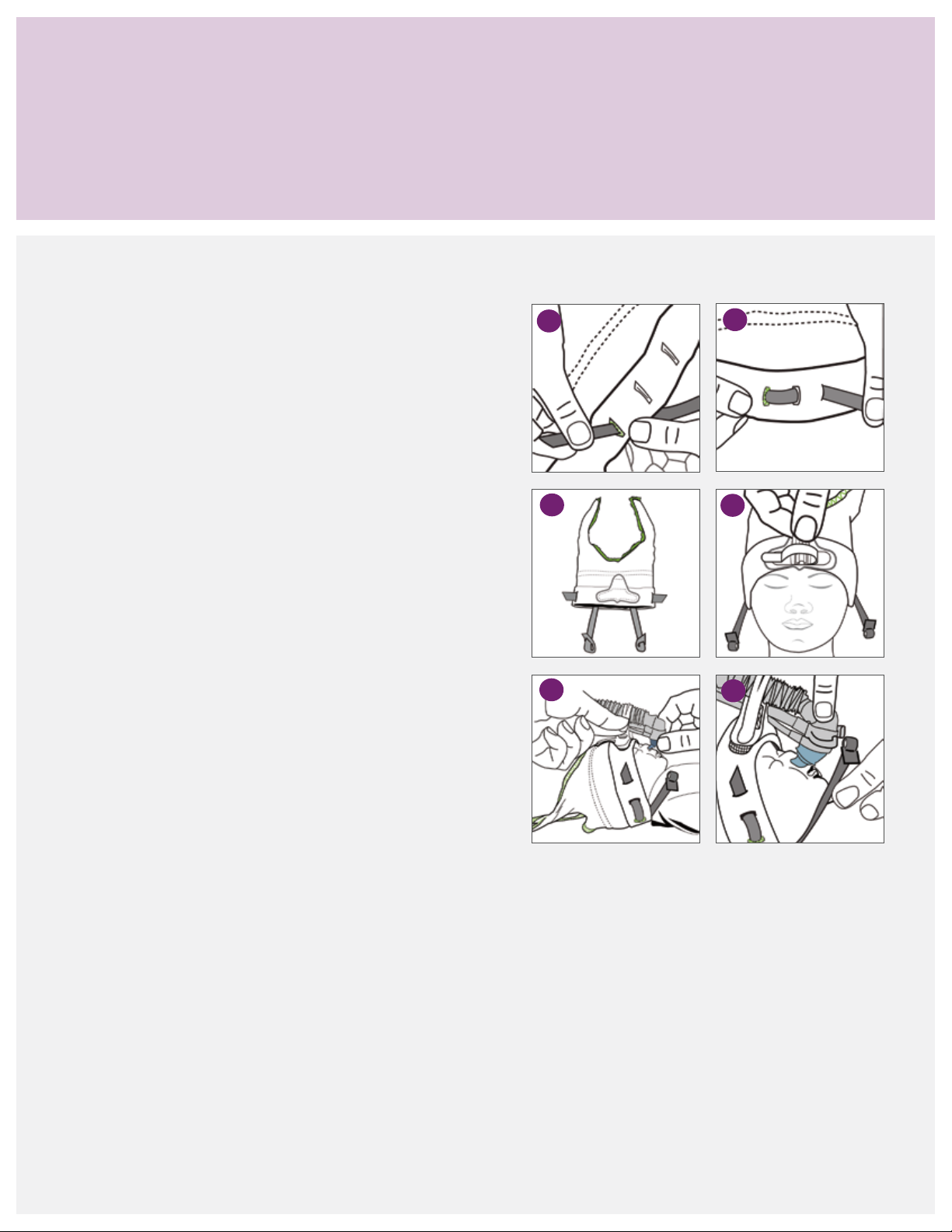
Bonnet application (alternative method 1)
The previous section outlined the most common method
for applying the bonnet. However, some clinicians may find
Thread the gray straps to the bonnet
As one alternative method, to apply the bonnet with gray
straps pre-threaded:
1. Create a loop on both straps. Take the slanted end of the
gray strap and pull through the slit on the opposite end
to form a loop.
2. Starting from the under side of the bonnet, thread up
through the colored hole, down through the center hole
and back up through the last hole.
3. The excess length of the gray strap should be before the
colored hole. When laid flat, the longer part of the strap
is at the back of the bonnet.
it more convenient or easier to use one of the methods
described in the following pages.
1
3
2
4
4. Pull the bonnet down over the patient’s head and ensure
the gray straps are brought forward and resting on the
side of the face. Attach the support cradle to the bonnet.
5. Use one hand to align the generator with the interface
perpendicular to the nose, and use the other hand to
position the exhaust tube over the support cradle.
Secure the exhaust tube, drive and pressure lines to
the support cradle.
6. While holding the generator assembly in place, take
the gray strap and place the loop over the quick secure
tab. Pull tight on the loop to adjust the tension of the
gray strap.
7. Repeat the process on the other side, and conduct a
final inspection.
Note: During the bonnet application, ensure the straps
are pulled forward and are not caught underneath the
back of the bonnet. If the loop pulls out, pull it open
before attaching it to the quick secure tab. Another
clinician should assist with the application.
5
6
38
Page 41

Bonnet application (alternative method 2)
A second method for applying the bonnet is attaching the
generator assembly to the bonnet prior to application. All
three methods discussed are acceptable ways to apply the
Attach the generator assembly to the bonnet
Another option for applying the bonnet is to attach
the generator assembly, interface and support cradle
prior to application.
1. Prepare the generator assembly as indicated in the
previous section. Attach the desired interface and
connect the gray straps to the quick secure tabs.
2. Center the support cradle on the application pad.
3. Place the drive and pressure lines in the support cradle
with the exhaust tube resting on top. Wrap the securing
strap around the exhaust tube, and attach it to the hook
material on the side of the support cradle. Keep a little
slack in the securing strap to freely move the generator
when ready to position it.
bonnet and generator assembly. Clinicians should use
the method that they are most comfortable with and best fits
the situation.
Note: The preparation of the bonnet and generator
assembly can be completed prior to application. The
actual process of applying it to the infant may be a little
cumbersome. It takes practice to keep the generator
assembly from brushing against the infant’s face while
pulling the bonnet down over the head. Ask another
caregiver to assist during the application process.
4. Thread the side straps onto the bonnet to fasten the
generator assembly to the bonnet.
5. Pull the bonnet and generator assembly down over
the infant’s head. Make any necessary adjustments to
properly position the generator and interface over the
infant’s nasal area.
6. Insert the nasal prongs or position the mask. Adjust the
tension of the side straps.
7. Complete a final inspection of the set-up. Confirm the
infant’s ears are covered and the bonnet’s edge is at the
brow line. Check that the interface is properly positioned
and a good seal is achieved.
39
Page 42

Incorrect application of xation device and generator assembly
Properly sizing and placing the fixation device, headgear or
bonnets is essential for the proper alignment and stability
of the generator assembly. Too small and too tight of a
fixation device may cause head molding or skin irritation.
Incorrect headgear position
1. Headgear straps 1 and 3 are too high on the forehead,
and the center strap is pulled too tight.
2. The center strap 2 is not midline to the nasal profile.
Corrective action: Reposition the headgear with forehead
straps 1 and 3 positioned at the brow line, and center
strap 2 over the crown and midline with the nose.
Incorrect headgear size
3. The headgear is too small, not covering the ears and
sitting too high on the back of the head.
4. The headgear is too large, causing folds or gaps in the
back of the headgear. The side straps are too long.
If the fixation device is too large, slippage can occur,
creating additional torque on the generator assembly
or dislodging the interface.
1
3
2
4
Corrective action: Recheck the head circumference
measurement and resize it as indicated.
Incorrect exhaust tube position
5. The support strap is not wrapped over the exhaust tube.
6. The exhaust tubing pulls forward.
Corrective action: Unhook the support strap and position
the exhaust tube on top of the support cradle. Wrap the
support strap over the exhaust tube, and secure it to the
side of the support cradle. Ensure the slit in the support
strap fits over the corrugate.
Reposition the exhaust tube and circuit to follow the
curvature of the head.
Incorrect support cradle application
7. The support cradle overlaps the edge of the forehead
strap and does not align with midline to the nasal profile.
Corrective action: Remove the support cradle
and reposition it in the middle of the forehead
and center straps.
6
5
7
40
Page 43

Incorrect bonnet position
1. The bonnet is seated too high on the forehead.
2. The support attachment pad is not midline to the
nasal profile.
Corrective action: Reposition the bonnet. The side of
the bonnet should cover the infant’s ears, and the front
of the bonnet should sit at the brow line.
1
2
Incorrect exhaust tube position
3. The support strap is not wrapped over the exhaust tube.
4. The exhaust tubing pulls forward, away from
the infant.
Corrective action: Reposition the support strap. The
exhaust tube should sit on top of the support cradle
with the securing strap around it. Ensure the slit in the
securing strap is over the corrugate.
Remove the support cradle, and reposition it in the
middle of the forehead and center straps.
Incorrect bonnet size
5. The bonnet is too small, not covering the infant’s ears
and sitting too high on the forehead. The side strap lies
too close to the eyes.
6. The headgear is too large. Excessive material is causing
folds to occur.
Corrective action: Recheck the head measurements.
Measure from the center of the forehead to the nape
of the neck, and back to the center of the forehead.
Select the appropriate bonnet size.
4
3
5
6
41
Page 44

Incorrect application of generator assembly and interface
Properly sizing and placing the patient interface are
essential for optimal therapy delivery. Incorrectly applying
the interface may lead to air leaks, pressure points, nasal
injury and therapy interruption.
Incorrect nasal prong position
1. One prong is not in the nostril.
Corrective action: Remove the prongs and reinsert the
prong tips into each nostril.
2. The base of the prongs is not sitting properly on the
generator receiver.
Corrective action: Remove the interface and reapply it
while ensuring the interface is evenly seated.
Side straps are too tight
3. The prongs are in the nostrils too far, compressing
the bellows.
Conduct routine checks according to the facility’s protocols
to ensure the proper placement of the interface.
1
3
2
4
4. The base of the interface is resting on the apex, and
the prongs are pressing against the nasal septum.
Corrective action: Release the tension on the straps
until the tops of the bellows are visible. Only the upper
portion of the prongs should be in the nares. Ensure the
generator assembly is properly positioned over the nares.
Improper generator alignment with the infant’s nose
5. The nasal prong and generator placement are too far
forward, causing the prongs to collapse.
6. The headgear is positioned too far back on the forehead,
causing the prongs to kink.
Corrective action: If the generator assembly is positioned
in front of the nose, the prongs bend. Loosen the
securing strap on the support block and reposition the
generator assembly and nasal prongs over the infant’s
nares. If the generator assembly is positioned incorrectly,
it affects the angle of the prongs and causes them to
bend or collapse. Ensure the headgear is properly placed
above the brow line. Loosen the support strap and slide
the generator assembly forward until the generator head
is perpendicular to the apex of the infant’s nose.
5
6
42
Page 45
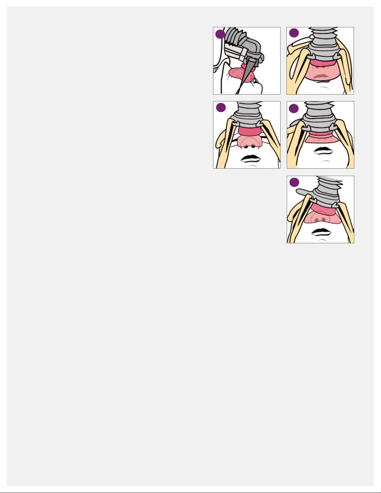
Improper mask size
1. The mask is too large if the top of the mask rests on
the glabella, the area between the eyebrows.
2. The mask is too large if the bottom of the mask covers
the infant’s lips.
3. The mask is too small if the mask does not cover the
perimeter of the nose and the bottom of the mask
occludes nares.
Corrective action: Use the sizing guide to select the
proper mask size.
Incorrect side strap tension
4. The straps are too tight if the bellow is compressed,
and the cushion has collapsed.
5. The strap tension is uneven if the bellow is compressed
on one side.
Corrective action: Loosen the side straps on the fixation
device. Lift the mask up, and reposition it on the infant’s
face. Readjust the strap tension to ensure the bellow and
cushion are not collapsed. The infant’s nares should be
clearly visible in the assessment window.
1
3
2
4
5
Tip: The interface must be the correct size, and the fixation
device must be properly applied to ensure the generator
assembly is properly aligned and stable.
43
Page 46

Final inspection of nasal interface placement
After applying the fixation device and generator assembly,
conduct a final check for the proper placement of the nasal
prongs and mask. A properly sized and placed interface
Nasal prong placement
For proper nasal prongs placement, check the following:
• The bellows are visible, not compressed. If the bellows
are compressed, use the side straps on the xation device
to adjust the tension applied to the nasal prongs. Loosen
the straps until the infant’s nasal septum is visible and
the bellows pop up.
• The generator and prongs are not touching the upper lip
or the apex of the nose.
• The prongs are not kinked or folded over.
• The upper portions of the prongs are in
both nares.
is key to the success of nCPAP therapy. Confirm that the
prescribed pressure is being delivered.
• The generator and interface are perpendicular to
the infant’s nose and not leaning to one side.
• The base of the interface is placed evenly on the
generator receiver.
• The prongs create a good seal with minimal or no leaks.
• No blanching is on the outer side of the nares. This
indicates the prongs are too large.
Nasal mask placement
For proper nasal mask placement, check that:
• The generator and mask are centered over the
nasal area.
• The mask covers the perimeter of the infant’s nose.
• The mask sits midline between the nose and upper
lip. Make sure the mask is not resting on the lip or
blocking the nares.
• The bellow is visible, not compressed.
• The infant’s nares and septum are visible in the
assessment window.
• The mask is seated below the infant’s eyes and rests
on the bridge of the nose.
• The top of the mask is not resting on the glabella,
the area between the eyebrows.
• A good seal is formed with minimal or no leaks.
The prescribed pressure is being met.
• The side straps are not too tight.
• The mask is fully inated, not collapsed. If collapsed,
the tension on the side straps may be too tight.
Loosen the straps until the below and assessment
window are visible.
44
Page 47

Self assessment and
return demonstration
Using the training doll provided, follow the steps outlined
and document the measurements.
1. Measure the doll’s head and select the appropriate
headgear size.
2. Measure the doll’s head and select the appropriate
bonnet size.
3. Use the sizing guide to select the correct interface size.
Nasal prongs:
Nasal mask:
4. Apply the xation device (bonnet or headgear).
5. Attach the generator assembly with the interface to
the xation device.
6. Inspect for proper application on the doll and obtain
feedback from the instructor or another participant.
Observation skills assessment
This Infant Flow LP system has not been applied correctly.
Identify at least four application errors:
45
Page 48

Observation skills assessment
This Infant Flow LP system has not been applied correctly.
Identify ve application errors:
Are there any additional application errors?
Notes:
46
Page 49

Routine nCPAP care
Final inspection and routine care
From the initial application of nCPAP therapy throughout
its progress, inspect the system after set-up and routinely,
every three to four hours to ensure therapy effectiveness
and infant comfort. These checks can be carried out with
other routine assessments to minimize stimulation in
Hourly
• Verify the infant is receiving prescribed therapy, and
check for leaks.
• Check that the generator assembly is stable, secure and
not pulling upward on the nose. Should the fixation
device or generator appear to be out of alignment once
applied, disassemble the fixation device and start over.
• Inspect the fixation device and straps for proper
placement and tension. Adjust them as needed to
maintain a proper fit, using the least amount of tension
possible to maintain stability. During inspection:
º Confirm the infant’s ears are not folded and
normally positioned.
º Ensure the straps are not twisted.
º Check the humidifier chamber water level.
Assessment times (at least every three to four hours)
• Inspect the skin integrity around the nasal area for
deformities or irritation. Gently massaging the contact
area may help stimulate circulation.
• Document any changes in the condition of the
infant’s nose.
the infant. The type and frequency of monitoring and
assessment carried out varies depending on each facility’s
policies and procedures and individual patient needs. This
section is only intended as suggested guidelines.
• Ensure the proper prong size. With prongs, the infant’s
septum should be clearly visible without compressed
bellows. With a mask, the infant’s eyes are visible and
nares are not blocked.
• Inspect for nasal mucosal damage due to a lack
of humidication.
• Monitor for gastric insufation and
abdominal distention.
Daily
• Document and continue assessing the nasal interface.
Include the size of the interface and any changes.
• Check the head measurement, and document the
xation device size.
Routine respiratory monitoring
• CPAP administered
• Cycle rate
• T-high setting
• MAP
• Delivered FiO
2
• Consider alternating the use of prong and mask
interfaces with each infant to avoid breaking down
the nasal area.
47
Page 50

Infant assessment and monitoring
Nasal care
3,5,17
• Skin color
• Chest wall stability (e.g., retractions)
• Infant’s behavior (e.g., irritability)
• Skin condition around the prong or mask interface
• Respiratory rate
• Oxygen saturation
• Heart rate and rhythm
• Blood gas values
• Chest x-rays
• Perfusion-BP, peripheral pulses
• Abdominal girth—may need to insert an
orogastric tube
By utilizing this information, members of the
multidisciplinary team can provide an individualized
plan of care.
Humidification
A heated humidier is recommended to warm and
humidify the delivered gases to prevent the mucosal
lining from drying. Routinely check the generator
assembly and interface, and clear them of any mucous
or water droplets. If excessive condensation is present,
check the water level in the chamber, remove the
unheated section of the circuit or lower the humidier
temperature setting.
Prevention is the key to reducing nasal septum
damage. Preterm infants have very thin, fragile skin
due to the immature development of the stratum
corneum, which makes the skin particularly vulnerable
to damage. If subjected to continuous pressure, friction
and/or moisture, the skin will begin to break down.
Skin erosion can occur within a matter of a few hours.
Diligence in monitoring the nasal area from the bridge
to the septum is essential. Avoiding contributing
factors help to maintain an intact septum:
• Use the correct nasal prong size. Prongs that are too
large cause nare blanching. If the prongs are too
small, they may go too far up the nose and press up
against the septum.
• Ensure the side strap tension is not too tight.
• Frequently inspect the skin integrity. If noting signs
of erosion or grazing, remove the pressure, friction
or moisture. Consider alternating the prongs and
mask to change the point of pressure.
• Do not use creams, oil or gels.
• Do not cover an injured septum with hydrocolloid
shields. The increased moisture may further break
down the area.
• Use hydrocolloids and other skin shields with
caution. The skin and shields can trap moisture,
or the shield can slip and block the nasal passage.
Positioning
3,5,6
An infant on CPAP can be positioned in any position—the
prone, lateral or supine—as long as it promotes comfort
and optimal airway posturing. Repositioning is essential
to the infant’s neurodevelopmental and respiratory
outcomes. If the exion of the infant’s head and neck is
too pronounced, the airway may be compromised, but
this can be resolved by gentle extension. Positioning aids
may be benecial. Routine positioning allows thorough
assessments by the clinicians. The infant should be
repositioned as per facility standards.
48
Page 51

The infant’s nares may take on a more rounded
appearance when the prongs have been in place for
a time. This is only temporary, and the nares will return
to normal size after therapy. Changing the size of the
infant’s interface during the course of treatment may be
necessary. Keep the nasal prong/mask sizing guide at
the bedside to aid the continued assessment.
Suctioning
nCPAP is noninvasive therapy, and suctioning should
only be performed according to clinical need. Over
vigorous suctioning may lead to tissue damage and
irritate the mucous linings, increasing secretion
production in response.
Kangaroo care
3–6
Infants on CPAP should be stable enough to be held.
Kangaroo care or similar types of parent/infant contact
is not contraindicated and should conform to the
facility’s standards.
Feeding
3–5
nCPAP is not a contraindication to feeding. Infants
receiving nCPAP can be breast, bottle or tube fed,
depending on their overall status. The clinician must
assess each infant accordingly when introducing a feeding
regime. Mild gastric ination is associated with nCPAP
therapy. An orogastric tube may be used to aspirate air
prior to feeding. Nasogastric feeding is not recommended
as it impedes the xation of the nCPAP interface and
signicantly adds to the WOB.
17
Notes:
49
Page 52

Frequently asked questions
Infant Flow LP generator assembly and interface
Q. What does LP stand for?
A. Low pressure. The special patent design of the dual jets
requires a lower driving pressure than other variable
flow generators.
Q. Can I use my bonnets from the original Infant Flow
nCPAP system with the new Infant Flow LP system?
A. No. The Infant Flow LP bonnets have a special pad
that attaches to the support cradle. The support cradle
lifts the generator assembly up and positions it at the
correct angle over the nose. It also provides stability for
the generator. The original Infant Flow bonnets do not
provide the extra height needed to properly position
the generator assembly.
Q. Are the prongs and mask from the original Infant Flow
and AirLife nCPAP systems compatible with the Infant
Flow LP generator?
A. No. The Infant Flow LP generator is keyed specifically
for the Infant Flow LP nasal prongs and masks.
Q. Can the generator assembly and fixation devices be
used on more than one patient?
A. No. The Infant Flow LP system is for single patient
use only.
Q. How can I decrease the noise generated by the system?
• Use an Infant Flow silencer connected to the
expiratory limb of the circuit to dampen the noise.
• Take care when using the silencer, as it may add
resistance to the system. If the filter becomes wet,
it increases resistance and WOB. Inspect the silencer
frequently, and replace it if wet. The resistance
caused by the filters varies according to the size and
type of filter material. Only use the silencer/filter
approved by CareFusion.
• Attach an extra length of corrugated tubing to the
end of the exhalation tube to direct gas flow away
from the infant and clinicians. These extension tubes
can be ordered separately.
Q. The masks keep collapsing. What should I do?
A. Check the position and placement of the generator
assembly. The generator head should be perpendicular
to the apex of the nose. If the position is too far back
or forward, it changes how pressure is applied to the
bellows and causes the mask to collapse. Check the
tension on the fixation side straps. If they are too tight,
they collapse the bellows and the mask.
Q. What can I do to prevent the headgear fixation
from slipping?
A. Measure the circumference of the head to ensure
the correct headgear size is used. Readjust the straps
until the headgear fits snugly with the forehead straps
resting at the brow line and the scalloped edge at the
nape of the neck. If the headgear is stretched out of
shape, replace with new headgear.
Q. How can I keep the prongs in place?
A. Ensure the correct prong size is used. Check the
alignment of the support cradle and generator
assembly. The generator assembly should be
perpendicular to the nasal profile. Ensure the
headgear or bonnet is properly sized and snug
to prevent the headgear from moving.
50
Page 53

Infant Flow LP generator assembly and interface (continued)
Q. How do I prevent nasal septal injury?
• Use the correct nasal prong and mask size. Prongs
that are too large may cause excessive pressure
against the nares and septum. Prongs that are too
small may increase movement and friction.
• Avoid overtightening the xation side straps.
• Properly align the support cradle and generator
assembly to the nasal area.
• Frequently inspect the nasal area for skin irritations,
and remove any moisture.
• Keep the generator assembly positioned to minimally
contact the nasal interface to the infant’s skin.
• Alternate between the nasal prongs and
mask interface.
• Use positioning aids to help keep the infant in
position if the bed is tilted. Otherwise, the infant may
migrate down, causing the circuit to pull against the
nasal septum.
• Do not use creams, gels, lubricants or hydrocolloid
products, as they may lead to excessive moisture and
undermine the skin integrity.
• Refer to the Routine Inspection section, nasal care,
for a more detailed description.
Q. What causes nasal blanching?
A. Two main causes are the prongs are too large or
incorrectly positioned. Recheck the measurement.
If the selected prong is the best size, try dilating the
nares before inserting the prongs. Insert only one
prong into the nare, and allow it to dilate. Remove
the prong and repeat the insertion with the other
nare. Then, try inserting both prongs.
Q. Can I prevent the “pig nose” appearance, often
associated with nCPAP?
A. The “pig nose” is caused by the nasal interface and
generator pushing up against the nasal septum for
an extended period of time. This occurs when the
generator assembly is not properly aligned with the
infant’s nose. If the generator assembly sits too far
back in the support cradle, it applies pressure against
the nose. If the headgear or bonnet are too high
on the forehead and not at the browline, it causes
the generator assembly to pull back and the nasal
interfaces to push up against the septal area.
Q. How do we clean the circuits, prongs, masks,
headgear and bonnets between patients?
A. All of these devices are for single patient use only
and should not be reused.
nCPAP therapy
Q. The infant has thickened oral and nasal sections. Do I
need to carry out routine suctioning?
A. When receiving nCPAP therapy, routinely suctioning the
infant’s oropharynx and nasopharynx is not required.
Suctioning should only be carried out with clinical need.
Over vigorous suctioning can cause further secretion
production in response to the procedure. If the infant
exhibits signs of increased WOB or distress, suctioning
may be indicated.
Q. Can you nebulize medication through the Infant Flow
LP generator?
A. No. The system is not designed for the nebulization
of medications. If the nebulizer was placed in line
prior to the impinging jets, the majority of the
medication would be pushed out the exhalation tube.
The additional flow used for the nebulizer would
impact the pressure delivery.
51
Page 54

nCPAP therapy (continued)
Q. Is humidification required with nCPAP?
A. Humidifying and warming inspired gases are essential
in nCPAP therapy. The high gas flow may dry the
mucosa, decrease mucociliary action and increase
airway resistance.
Q. Do infants receiving nCPAP therapy suffer from
stomach distension?
A. Gastric distension is caused by the infant swallowing air.
If mild distension occurs, an orogastric tube can be used
to aspirate the air from the stomach. Aspirate excess air
prior to feedings. Follow the facility standard of care.
Avoid using nasogastric tubes, as they interfere with the
seal with a nasal mask. With nasal prongs, the clinician
has to select a smaller prong size, which can create
leaks. Nasogastric tubes are also associated with higher
WOB for the infant.
Q. Can I use hydrocolloid tape or similar materials around
the nasal area?
A. Take care when using hydrocolloid tape to ensure that
moisture does not collect under the tape, and change
the tape frequently. Moisture under the hydrocolloid
tape may cause it to slip, blocking the nares,
dislodging the prongs or causing the prongs to kink.
The moisture under the tape may increase the risk for
skin breakdown. If the proper prong size is used and
the generator is positioned properly, hydrocolloid tape
should not be necessary.
Q. Can a pacifier be used with an infant on nCPAP?
A. Yes. A pacifier does not interfere with nCPAP therapy.
If the infant’s mouth is open, it may decrease the
delivered pressure. The pacifier helps keep the infant’s
mouth closed.
Q. Can nCPAP be used on infants with a cleft palate?
A. Upper airway abnormalities, such as cleft palate, choanal
atresia and a tracheoesophageal fistula, are considered
contraindicated for nCPAP therapy.
Q. Can the infant receive phototherapy while on nCPAP?
A. Yes, phototherapy is not a contraindication to nCPAP
therapy. Place eye patches over the eyes before starting
therapy, and avoid obstructing the view of the nasal
interface and septum.
Infant Flow SiPAP nCPAP driver
Q. When should I calibrate the oxygen sensor?
A. The oxygen sensor drifts with extended use. At a
minimum, calibrate the oxygen sensor with the initial
set-up and circuit changes.
Q. The displayed O
oxygen control dial. What is the correct value?
A. The markings on the oxygen control dial (blender)
are for reference only. For an accurate reading, refer
to the O
% displayed on the screen. If a significant
2
difference exists between the two, recalibrate
the oxygen sensor.
52
% does not correlate to the setting the
2
Q. I have disabled the oxygen sensor. Do I need to use an
external oxygen analyzer?
A. Whenever the oxygen sensor has been disabled, you
must use an external oxygen analyzer to monitor the
delivered oxygen.
Q. What causes the blender alarm to sound?
A. The air and oxygen hoses are not connected correctly to
the gas sources. The blender alarm has been triggered
from the difference in pressures ≥ 2 bar (29 psi).
Page 55

Infant Flow SiPAP nCPAP driver (continued)
Q. What triggers the SiPAP nCPAP driver to alarm?
A. Refer to the operator manual for the list of alarm
triggers. Some of the more common alarms are:
• The alarms were not reset after a change in CPAP
level or oxygen setting. To x, hold the alarm reset
bar down for three seconds to reset the alarm
thresholds.
• Check the system for leaks. The nasal interface may
be improperly positioned or the infant’s mouth may
be open.
Q. Why does the SiPAP not deliver a pressure boost when
the manual breath button is pressed?
A. When the system is in the CPAP mode, the high
flowmeter needs to be set for the manual breath to
be active.
Q. Why is the system not reaching the high pressure
setting? The SiPAP system is set at 10 cmH
O/5 cmH2O,
2
T-high 0.3 sec, Rate 20, 30%. Even when the flow rate
on the high pressure flowmeter was increased, the
maximum high CPAP reached was 9 cmH
O.
2
A. The SiPAP system has a slow ramp to the high pressure
setting. If the inspiratory time is not long enough, the
high pressure is not reached. First, check the breathing
circuit and generator assembly for leaks. If the problem
does not correct, increase the T-high setting, monitor
for an increase in the high pressure and increase the
T-high until the desired pressure is reached.
Q. Can the SiPAP nCPAP driver deliver nitric oxide?
A. The FDA has approved the use of the INOMAX
DS with the SiPAP driver for delivering nitric oxide.
Refer to the Ikaria INOMax operator manual for the
directions of use.
Q. When the system is connected to the infant,
a flow rate of 9 LPM does not deliver 5 cmH
O.
2
Why is this?
• A leak is in the breathing circuit and
generator assembly.
• The prongs and mask interfaces are not the
proper size.
• The strap tension is too tight, which can break
the seal on the interface.
• Leaks in the circuit could be caused by loose
connections, pinholes or temperature probes
not fully inserted in the temperature port.
Q. Air is backing up into the humidifier’s water auto-feed
system. What should I do?
A. Ensure the height of the water bag is at least 50 cm
above the humidifier chamber. If air still accumulates,
apply a pressure cuff around the water bag.
53
Page 56

Self assessment
1. Why is selecting the proper prongs/mask size important?
2. When properly positioned, the generator should sit
to the infant’s face.
3. List at least three assessments that should be conducted
every three to four hours while on nCPAP therapy:
4. List three ways to help prevent nasal injury:
5. The Infant Flow LP components are interchangeable with
the original Infant Flow nCPAP system.
True False
8. Medications can be nebulized through the Infant
Flow LP generator.
True False
9. A ow rate of 9 LPM will deliver how much CPAP?
3 cmH
5 cmH
7 cmH
9 cmH
O
2
O
2
O
2
O
2
Notes:
6. List three actions that help prevent nasal injury:
7. Explain why the SiPAP system does not deliver a breath
while the manual breath button is pressed:
54
Page 57

Glossary
Abdominal respiratory sensor: A pressure sensor
taped to the infant’s abdomen to sense respiratory
efforts. The signal returns back to the SiPAP driver
through a transducer interface.
Added work of breathing (WOB): The extra effort
or work that is created by the introduction of an artificial
system used to supply enriched gas to support the infant.
Apnea of prematurity: Cessation of breathing in a
premature infant for 15 seconds and associated with
hypoxia or bradycardia.
Bubble CPAP (B-CPAP): A constant flow of heated and
humidified gas, where the level of pressure is controlled
by the depth of the exhalation tube in a water container.
BiPhasic: Bi-level noninvasive ventilation mode, which
cycles between high and low CPAP levels on a timed
basis. For use with a spontaneously breathing infant.
Bradycardia: When the heart rate in a newborn falls
below 100 beats per minute.
Breathe: The inspiratory phase as expiration is passive.
CPAP: The application of positive pressure to the airways
of a spontaneously breathing infant throughout the
respiratory cycle.
Conventional CPAP (V-CPAP): Noninvasive ventilation
utilizing a traditional mechanical ventilator to deliver CPAP.
Extubation: ET tube removal.
Fixation device: The device used to secure the generator
to the infant, referring to either the bonnet or headgear.
Fluidic flip: The key to the functionality of the Infant
Flow LP Generator. This occurs within the generator
in harmony with the infant’s breathing pattern. The
patented internal design of the generator manipulates
the gas flow to provide a stable CPAP level at the
infant’s airway. Because the device depends on fluidic
action and not valves or other mechanical devices, the
response time to the infant’s respiratory effort is almost
instantaneous. During expiration, gases are flipped away
from the infant, and during inspiration, the flow flips back.
Generator assembly: The generator, exhaust tube,
proximal pressure line, drive pressure line, support block
and interface.
High flow nasal cannula (HFNC): A constant flow of
heated, humidified gas that potentially delivers positive
distending pressure via a nasal cannula.
Infant Flow SiPAP Plus driver: A dedicated flow driver
for use with infant nCPAP variable flow generators. The
SiPAP Plus driver provides two modalities of respiratory
support: nCPAP and BiPhasic. Infant monitoring, alarms
and safety features are built into the driver to ensure the
system operates correctly and the infant’s respiratory
efforts are supported safely.
Infant Flow LP SiPAP Comprehesive driver: A
dedicated flow driver for use with infant nCPAP variable
flow generators. The comprehensive model provides
three modalities of respiratory support: nCPAP, BiPhasic
and BiPhasic trigger. The trigger mode utilizes the
respiratory abdominal sensors to synchronize supported
breaths. Infant monitoring, alarms and safety features
are built into the driver. Not available in the U.S.
Infant Flow LP nCPAP generator: A single infant
use, dual-jet generator that delivers the CPAP therapy.
The patented Infant Flow LP Generator is designed to
reduce the added work of breathing by providing active
assistance to the infant on inspiratory and expiratory
phases of the respiratory cycle. The infant interface is
provided by the use of nasal prongs and nasal masks.
55
Page 58

Infant Flow transducer: The connection from the SiPAP
driver to the respiratory abdominal sensors for respiratory
rate monitoring and synchronization.
Interface: Either a nasal mask or nasal prong connected
to the generator used to deliver nCPAP.
Low birth-weight infant: An infant born weighing less
than 2,500 grams.
Nasal CPAP (nCPAP): A continuous flow of gas
administered through nasal prongs inserted in the infant’s
nares or a nasal mask placed around the perimeter
of the nose.
Nasogastric tube (NGT): A soft, flexible tube that is
passed through the nose and oropharynx, down into
the esophagus, where it enters the stomach. Nutrition
and oral medications can be administered through the
nasogastric tube.
Neonate: A newborn infant from birth to four weeks.
Orogastric tube (OGT): A soft, flexible tube that is
passed through the mouth and oropharynx, down into
the esophagus, where it enters the stomach. Nutrition
and oral medications can be administered through the
orogastric tube.
Variable flow CPAP (VF-CPAP): The creation of a CPAP
level based on flow utilizing fluidic principles. Rather
than provide a constant flow of gas, VF-CPAP provides
a direction of gas flow that depends on the infant’s
respiratory cycle. When the infant exhales, the flow flips
away from the nares and then, flips back as the infant
begins to inhale.
Very low birth-weight: An infant weighing less that
1,500 grams at birth.
Work of breathing (WOB): The amount of effort breath.
Premature/Preemie: An infant born before 37 weeks
of gestation.
Respiratory acidosis: A decrease in arterial Ph below
7.35 from the norm and usually associated with retention
of arterial CO
.
2
Respiratory distress syndrome (RDS): A common
respiratory disorder in premature infants caused by the
deficiency of surfactant defined by respiratory difficulty.
RDS is characterized by rapid respirations, nasal flaring,
intercostal retractions, expiratory grunting, and diffuse
haziness and infiltrates noted on chest x-rays. Treatment
requires either supplemental oxygen or respiratory support.
Surfactant: A phospholipid, which reduces the surface
tension, allowing the lungs to become more compliant.
Support cradle: The support cradle stabilizes the
generator assembly and helps maintain proper alignment
with the nasal area.
Time high (T-high): In bi-level or BiPhasic ventilation,
the set duration for the high CPAP setting.
56
Page 59

57
Page 60

References
1 Howson, C., Kinney, M., Lawn, J. Born Too Soon: The Global Action Report on Preterm Birth. March of Dimes, The
Partnership, Save the Children, World Health Organization. Geneva, 2012. 2 Pramanik, A. et al. Respiratory care
distress. Medscape, March 9, 2011. 3 Sankar, M., Sankar, J., Agarwal, R., Paul, V., et al. Protocols for administering
continuous positive airway pressure in neonates. J Pediatr, 2008, 75:473. 4 AARC practice guidelines. Application
of continuous positive airway pressure to neonates via nasal prongs, pasopharyngeal tube or nasal mask. Resp
Care, September 2004, 49(9):1100–1108. 5 Workbook: Clinical training workbook. CareFusion, July/August 2003.
6 Conner, M., de Klerk, R., de Klerk, A. Nasal continuous positive airway pressure (nCPAP) education and training
manual. Vermont Oxford Network, 2003, 2.4. 7 Robertson, N., McCarthy, L., Hamilton, P. et al. Nasal deformities
resulting from ow driver continuous positive airway pressure. Arch Dis Child Fetal Neonatal Ed, 1996, 75:F209–
F212. 8 Gregory, G., Kitterman, J., Phibbs, R., Tooley, W., et al. Treatment of the idiopathic respiratory-distress
syndrome with continuous positive airway pressure. N Engl J Med, 1971, 284:1333–1340. 9 Pandt, P., Courtney
SE, Pyon KH, et al. Work of breathing during constant and variable-ow nasal continuous positive pressure in
preterm neonates. Pediatric, 2001, 108(3):682–685. 10 Diblasi, R. Nasal continuous positive airway pressure
(nCPAP) for the respiratory care of the newborn infant. Respir Care, 2009, 54(9):1209–1235. 11 Moa, G., Nilsson, K.,
Zetterström H, et al. A new device for administration of nasal continuous positive airway pressure in the newborn:
An experimental study. Crit Care Med, 1988, 16(12):1238–1242. 12 Goehle, L. Variable ow nCPAP: Something
to ip about. Neo Intensive Care, 2010, 23(7). 13 Shelly, M. The humidication and ltration functions of the
airways. Respir Care Clin N Am, 2006 (2):139–148. 14 Restrepo, R., Walsh, B. Humidication during invasive and
noninvasive mechanical ventilation: 2012. Respir Care, 2012, 57(5):782–788. 15 Courtney, S. Infant ow SiPAP
implementation strategy. CareFusion. 16 Courtney, S., Pyon KH, Saslow JG, et al. Lung recruitment and breathing
pattern during variable vs. continuous ow nasal continuous positive airway pressure in premature infants:
An evaluation of three devices. Pediatrics, 2001, 107:304–308. 17 Squires, A., Hyndman, M. Prevention of nasal
injuries secondary to nCPAP application in ELBW infants. Neonatal Network, 2009, 28(1):13–27. 18 Wald, M.
Variety of expiratory resistance between different continuous positive airway pressure devices for preterm
infants. Articial Organs, 2011, 35(1):22–28. 19 Drevhammar, T., et al. Comparison of seven infant continuous
positive airway pressure systems using simulated neonatal breathing. Pediatr Crit Care Med, 2012, 13:e113–e119.
Caution—U.S. Federal Law restricts this device to sale by or on the order of a physician.
CareFusion
22745 Savi Ranch Parkway
Yorba Linda, CA 92887
800.231.2466 toll-free
714.283.2228 tel
714. 28 3.8 493 fax
carefusion.com
© 2013 CareFu sion Cor porati on or one of i ts sub sidiari es. All r ights re ser ved. Inf ant Flow, C areFus ion and th e CareFusion
logo are t radema rks or re giste red trademark s of CareFusion C orpora tion or on e of its su bsidia ries. R C2191 (0813/2 500)
 Loading...