


Technical Service Manual
Alaris® Syringe Module, 8110 Series
Alaris® PCA Module, 8120 Series
Supports: Guardrails® (Suite v7 or Later)
November 2010
RM |
IN |
E |
STA |
FUS |
|
||
ALA |
|
|
NDBY |
RATE (mL/h)
CHANNEL
SELECT
PAUSE
RM |
IN |
E |
STA |
FUS |
|
||
ALA |
|
|
NDBY |
RATE (mL/h)
CHANNEL
SELECT
PAUSE
CHANNEL |
CHANNEL |
OFF |
OFF |
RESTART |
RESTART |

General Contact Information
CareFusion
San Diego, California
http://www.carefusion.com/alaris
Customer Advocacy - North America
Clinical and technical feedback.
Phone: 888.876.4287
E-Mail: CustomerFeedback@carefusion.com
Technical Support - North America
Maintenance and service information support; troubleshooting.
United States: |
Canada: |
Phone: |
Phone: |
888.876.4287 |
800.387.8309 |
Customer Care - North America
Instrument return, service assistance, and order placement.
United States: |
Canada: |
Phone: 888.876.4287 |
Phone: 800.387.8309 |
|
|

|
|
TABLE OF CONTENTS |
|
|
|
Chapter 1 - General Information |
|
|
1.1 |
Introduction . . . . . . . . . . . . . . . . . . . . . . . . . . . . . . . . . . . . . . . . . . . . . . . . . . . . . . . . . |
. . . . . . . . . . . . . . . . . . . . . . . . . . . . . . . . . . . 1-1 |
1.2 |
Precaution Definitions . . . . . . . . . . . . . . . . . . . . . . . . . . . . . . . . . . . . . . . . . . . . . . |
. . . . . . . . . . . . . . . . . . . . . . . . . . . . . . . . . . 1-2 |
1.3 |
Specifications . . . . . . . . . . . . . . . . . . . . . . . . . . . . . . . . . . . . . . . . . . . . . . . . . . . . . . . |
. . . . . . . . . . . . . . . . . . . . . . . . . . . . . . . . . . 1-2 |
1.4 |
Operating Features, Controls and Indicators . . . . . . . . . . . . . . . . . . . . . |
. . . . . . . . . . . . . . . . . . . . . . . . . . . . . . . . . . 1-2 |
1.5 |
Accessories . . . . . . . . . . . . . . . . . . . . . . . . . . . . . . . . . . . . . . . . . . . . . . . . . . . . . . . . . |
. . . . . . . . . . . . . . . . . . . . . . . . . . . . . . . . . . 1-2 |
1.6 |
Alarms, Errors, Messages . . . . . . . . . . . . . . . . . . . . . . . . . . . . . . . . . . . . . . . . . |
. . . . . . . . . . . . . . . . . . . . . . . . . . . . . . . . . . 1-2 |
1.6.1 |
Silencing Alarms . . . . . . . . . . . . . . . . . . . . . . . . . . . . . . . . . . . . . . . . . . . . . . . . . . . . |
. . . . . . . . . . . . . . . . . . . . . . . . . . . . . . . . . . 1-2 |
1.7 |
Trumpet and Start-Up Curves . . . . . . . . . . . . . . . . . . . . . . . . . . . . . . . . . . . . . |
. . . . . . . . . . . . . . . . . . . . . . . . . . . . . . . . . . 1-2 |
Chapter 2 - Checkout and Configuration |
|
|
2.1 |
Introduction . . . . . . . . . . . . . . . . . . . . . . . . . . . . . . . . . . . . . . . . . . . . . . . . . . . . . . . . . . |
. . . . . . . . . . . . . . . . . . . . . . . . . . . . . . . . . . 2-1 |
2.2 |
New Instrument Checkout . . . . . . . . . . . . . . . . . . . . . . . . . . . . . . . . . . . . . . . . . |
. . . . . . . . . . . . . . . . . . . . . . . . . . . . . . . . . . 2-1 |
2.3 |
Configuration Options and Defaults - Syringe Module . . . . . . . . . . . |
. . . . . . . . . . . . . . . . . . . . . . . . . . . . . . . . . . 2-2 |
2.3.1 |
Factory Default Setting . . . . . . . . . . . . . . . . . . . . . . . . . . . . . . . . . . . . . . . . . . . . . |
. . . . . . . . . . . . . . . . . . . . . . . . . . . . . . . . . . 2-2 |
2.4 |
Configuration Setup - Syringe Module . . . . . . . . . . . . . . . . . . . . . . . . . . . . |
. . . . . . . . . . . . . . . . . . . . . . . . . . . . . . . . . . 2-2 |
2.4.1 |
All Mode . . . . . . . . . . . . . . . . . . . . . . . . . . . . . . . . . . . . . . . . . . . . . . . . . . . . . . . . . . . . . |
. . . . . . . . . . . . . . . . . . . . . . . . . . . . . . . . . . 2-3 |
2.4.2 |
Auto Pressure . . . . . . . . . . . . . . . . . . . . . . . . . . . . . . . . . . . . . . . . . . . . . . . . . . . . . . . |
. . . . . . . . . . . . . . . . . . . . . . . . . . . . . . . . . . 2-4 |
2.4.3 |
Back Off . . . . . . . . . . . . . . . . . . . . . . . . . . . . . . . . . . . . . . . . . . . . . . . . . . . . . . . . . . . . . |
. . . . . . . . . . . . . . . . . . . . . . . . . . . . . . . . . . 2-4 |
2.4.4 |
Fast Start . . . . . . . . . . . . . . . . . . . . . . . . . . . . . . . . . . . . . . . . . . . . . . . . . . . . . . . . . . . . |
. . . . . . . . . . . . . . . . . . . . . . . . . . . . . . . . . . 2-5 |
2.4.5 |
KVO . . . . . . . . . . . . . . . . . . . . . . . . . . . . . . . . . . . . . . . . . . . . . . . . . . . . . . . . . . . . . . . . . . |
. . . . . . . . . . . . . . . . . . . . . . . . . . . . . . . . . . 2-5 |
2.4.6 |
Max Rate . . . . . . . . . . . . . . . . . . . . . . . . . . . . . . . . . . . . . . . . . . . . . . . . . . . . . . . . . . . . |
. . . . . . . . . . . . . . . . . . . . . . . . . . . . . . . . . . 2-6 |
2.4.7 |
Near End . . . . . . . . . . . . . . . . . . . . . . . . . . . . . . . . . . . . . . . . . . . . . . . . . . . . . . . . . . . . |
. . . . . . . . . . . . . . . . . . . . . . . . . . . . . . . . . . 2-7 |
2.4.8 |
Pressure Limit - Disc . . . . . . . . . . . . . . . . . . . . . . . . . . . . . . . . . . . . . . . . . . . . . . . |
. . . . . . . . . . . . . . . . . . . . . . . . . . . . . . . . . . 2-8 |
2.4.9 |
Pressure Limit - No Disc . . . . . . . . . . . . . . . . . . . . . . . . . . . . . . . . . . . . . . . . . . . |
. . . . . . . . . . . . . . . . . . . . . . . . . . . . . . . . . . 2-8 |
2.4.10 |
Priming . . . . . . . . . . . . . . . . . . . . . . . . . . . . . . . . . . . . . . . . . . . . . . . . . . . . . . . . . . . . . . |
. . . . . . . . . . . . . . . . . . . . . . . . . . . . . . . . . . 2-9 |
2.5 |
Configuration Setup - Shared Infusion Pump and Syringe . . . . . . |
. . . . . . . . . . . . . . . . . . . . . . . . . . . . . . . . . . 2-9 |
2.6 |
Configuration Options and Defaults - PCA Module . . . . . . . . . . . . . . |
. . . . . . . . . . . . . . . . . . . . . . . . . . . . . . . . . . 2-9 |
Chapter 3 - Preventive Maintenance |
|
|
3.1 |
Introduction . . . . . . . . . . . . . . . . . . . . . . . . . . . . . . . . . . . . . . . . . . . . . . . . . . . . . . . . . . |
. . . . . . . . . . . . . . . . . . . . . . . . . . . . . . . . . . 3-1 |
3.2 |
Regular and Preventive Maintenance Inspections, Calibration . |
. . . . . . . . . . . . . . . . . . . . . . . . . . . . . . . . . . 3-1 |
3.3 |
Cleaning . . . . . . . . . . . . . . . . . . . . . . . . . . . . . . . . . . . . . . . . . . . . . . . . . . . . . . . . . . . . . |
. . . . . . . . . . . . . . . . . . . . . . . . . . . . . . . . . . 3-1 |
Chapter 4 - Principles of Operation |
|
|
4.1 |
Introduction . . . . . . . . . . . . . . . . . . . . . . . . . . . . . . . . . . . . . . . . . . . . . . . . . . . . . . . . . . |
. . . . . . . . . . . . . . . . . . . . . . . . . . . . . . . . . . 4-1 |
4.2 |
General Information . . . . . . . . . . . . . . . . . . . . . . . . . . . . . . . . . . . . . . . . . . . . . . . . |
. . . . . . . . . . . . . . . . . . . . . . . . . . . . . . . . . . 4-1 |
4.3 |
Display Board Assembly . . . . . . . . . . . . . . . . . . . . . . . . . . . . . . . . . . . . . . . . . . . |
. . . . . . . . . . . . . . . . . . . . . . . . . . . . . . . . . . 4-2 |
Alaris® Syringe Module (8110 Series)
Alaris® PCA Module (8120 Series)
Technical Service Manual
i

TABLE OF CONTENTS
Chapter 4 - Principles of Operation (Continued)
4.3.1 |
Microcontroller . . . . . . . . . . . . . . . . . . . . . . . . . . . . . . . . . . . . . . . . . . . . . . . . . . . . . . . . . . . . . . . . . . . . . . . . . . . . . . . . . . . . . . . . |
4-2 |
4.3.2 |
LED Display Driver . . . . . . . . . . . . . . . . . . . . . . . . . . . . . . . . . . . . . . . . . . . . . . . . . . . . . . . . . . . . . . . . . . . . . . . . . . . . . . . . . . . |
4-2 |
4.3.3 |
Comparator/Safety Monitor . . . . . . . . . . . . . . . . . . . . . . . . . . . . . . . . . . . . . . . . . . . . . . . . . . . . . . . . . . . . . . . . . . . . . . . . . . |
4-2 |
4.3.4 |
Status and Backlight LEDs . . . . . . . . . . . . . . . . . . . . . . . . . . . . . . . . . . . . . . . . . . . . . . . . . . . . . . . . . . . . . . . . . . . . . . . . . . . |
4-2 |
4.4 |
Logic Board Assembly . . . . . . . . . . . . . . . . . . . . . . . . . . . . . . . . . . . . . . . . . . . . . . . . . . . . . . . . . . . . . . . . . . . . . . . . . . . . . . . |
4-3 |
4.5 |
Drivetrain Assembly . . . . . . . . . . . . . . . . . . . . . . . . . . . . . . . . . . . . . . . . . . . . . . . . . . . . . . . . . . . . . . . . . . . . . . . . . . . . . . . . . . |
4-3 |
4.6 |
Drive Head . . . . . . . . . . . . . . . . . . . . . . . . . . . . . . . . . . . . . . . . . . . . . . . . . . . . . . . . . . . . . . . . . . . . . . . . . . . . . . . . . . . . . . . . . . . . |
4-4 |
4.7 |
Plunger Head Board Assembly . . . . . . . . . . . . . . . . . . . . . . . . . . . . . . . . . . . . . . . . . . . . . . . . . . . . . . . . . . . . . . . . . . . . . . |
4-4 |
4.8 |
Force Sensor Subsystem . . . . . . . . . . . . . . . . . . . . . . . . . . . . . . . . . . . . . . . . . . . . . . . . . . . . . . . . . . . . . . . . . . . . . . . . . . . . |
4-4 |
4.9 |
Pressure Sensor Subsystem (Syringe Module Only) . . . . . . . . . . . . . . . . . . . . . . . . . . . . . . . . . . . . . . . . . . . . . . |
4-5 |
4.10 |
Patient Handset Circuit and Door Lock Sensor Circuit (PCA Module Only) . . . . . . . . . . . . . . . . . . . . . . |
4-5 |
Chapter 5A - Corrective Maintenance - Syringe Module
5.1 |
Introduction . . . . . . . . . . . . . . . . . . . . . . . . . . . . . . . . . . . . . . . . . . . . . . . . . . . . . . . . . . . . . . . . . . . . . . . . . . . . . . . . . . . . . . . . . . . |
5A-1 |
5.2 |
Disassembly/Reassembly . . . . . . . . . . . . . . . . . . . . . . . . . . . . . . . . . . . . . . . . . . . . . . . . . . . . . . . . . . . . . . . . . . . . . . . . . . . |
5A-2 |
5.2.1 |
Removing Latch Assembly and Feet . . . . . . . . . . . . . . . . . . . . . . . . . . . . . . . . . . . . . . . . . . . . . . . . . . . . . . . . . . . . . . . |
5A-3 |
5.2.2 |
Removing IUI Connector Assemblies . . . . . . . . . . . . . . . . . . . . . . . . . . . . . . . . . . . . . . . . . . . . . . . . . . . . . . . . . . . . . . |
5A-4 |
5.2.3 |
Separating Rear Case from Chassis Assembly . . . . . . . . . . . . . . . . . . . . . . . . . . . . . . . . . . . . . . . . . . . . . . . . . . . |
5A-5 |
5.2.4 |
Removing Handle . . . . . . . . . . . . . . . . . . . . . . . . . . . . . . . . . . . . . . . . . . . . . . . . . . . . . . . . . . . . . . . . . . . . . . . . . . . . . . . . . . . . |
5A-6 |
5.2.5 |
Removing Flex Cable Retainer . . . . . . . . . . . . . . . . . . . . . . . . . . . . . . . . . . . . . . . . . . . . . . . . . . . . . . . . . . . . . . . . . . . . . |
5A-7 |
5.2.6 |
Removing IUI Board Assembly . . . . . . . . . . . . . . . . . . . . . . . . . . . . . . . . . . . . . . . . . . . . . . . . . . . . . . . . . . . . . . . . . . . . . |
5A-8 |
5.2.7 |
Removing Logic Board Assembly . . . . . . . . . . . . . . . . . . . . . . . . . . . . . . . . . . . . . . . . . . . . . . . . . . . . . . . . . . . . . . . . . . |
5A-9 |
5.2.8 |
Removing Internal Frame Assembly . . . . . . . . . . . . . . . . . . . . . . . . . . . . . . . . . . . . . . . . . . . . . . . . . . . . . . . . . . . . . . . |
5A-10 |
5.2.9 |
Removing Drivetrain Assembly . . . . . . . . . . . . . . . . . . . . . . . . . . . . . . . . . . . . . . . . . . . . . . . . . . . . . . . . . . . . . . . . . . . . . |
5A-11 |
5.2.10 |
Removing Display Board Assembly . . . . . . . . . . . . . . . . . . . . . . . . . . . . . . . . . . . . . . . . . . . . . . . . . . . . . . . . . . . . . . . . |
5A-12 |
5.2.11 |
Removing Pressure Sensor Board Assembly . . . . . . . . . . . . . . . . . . . . . . . . . . . . . . . . . . . . . . . . . . . . . . . . . . . . . |
5A-13 |
5.2.12 |
Removing Top Disk Holder . . . . . . . . . . . . . . . . . . . . . . . . . . . . . . . . . . . . . . . . . . . . . . . . . . . . . . . . . . . . . . . . . . . . . . . . . |
5A-14 |
5.2.13 |
Removing Sensor Board Assembly . . . . . . . . . . . . . . . . . . . . . . . . . . . . . . . . . . . . . . . . . . . . . . . . . . . . . . . . . . . . . . . . |
5A-15 |
5.2.14 |
Removing Syringe Size Sensor Assembly . . . . . . . . . . . . . . . . . . . . . . . . . . . . . . . . . . . . . . . . . . . . . . . . . . . . . . . . . |
5A-16 |
5.2.15 |
Removing Syringe Barrel Clamp Assembly . . . . . . . . . . . . . . . . . . . . . . . . . . . . . . . . . . . . . . . . . . . . . . . . . . . . . . . . |
5A-17 |
5.2.16 |
Removing Status Indicator Lens . . . . . . . . . . . . . . . . . . . . . . . . . . . . . . . . . . . . . . . . . . . . . . . . . . . . . . . . . . . . . . . . . . . . |
5A-19 |
5.2.17 |
Removing Housing Assembly and Guide Rod . . . . . . . . . . . . . . . . . . . . . . . . . . . . . . . . . . . . . . . . . . . . . . . . . . . . |
5A-20 |
5.2.18 |
Removing Motor/Pulley Assembly . . . . . . . . . . . . . . . . . . . . . . . . . . . . . . . . . . . . . . . . . . . . . . . . . . . . . . . . . . . . . . . . . . |
5A-21 |
5.2.19 |
Removing Leadscrew Assembly and Bottom Plate . . . . . . . . . . . . . . . . . . . . . . . . . . . . . . . . . . . . . . . . . . . . . . . |
5A-22 |
5.2.20 |
Removing Linear Sensor Assembly . . . . . . . . . . . . . . . . . . . . . . . . . . . . . . . . . . . . . . . . . . . . . . . . . . . . . . . . . . . . . . . . |
5A-23 |
5.2.21 |
Removing Force Sensor and Actuator Knob Assemblies . . . . . . . . . . . . . . . . . . . . . . . . . . . . . . . . . . . . . . . . |
5A-24 |
5.2.22 |
Removing Actuator Knob Assembly Parts . . . . . . . . . . . . . . . . . . . . . . . . . . . . . . . . . . . . . . . . . . . . . . . . . . . . . . . . . |
5A-25 |
ii
Alaris® Syringe Module (8110 Series)
Alaris® PCA Module (8120 Series)
Technical Service Manual

|
|
TABLE OF CONTENTS |
|
|
|
Chapter 5B - Corrective Maintenance - PCA Module |
|
|
5.1 |
Introduction . . . . . . . . . . . . . . . . . . . . . . . . . . . . . . . . . . . . . . . . . . . . . . . . . . . . . . . . . . . . . . . . . . . . . . |
. . . . . . . . . . . . . . . . . . . . . 5B-1 |
5.2 |
Disassembly/Reassembly . . . . . . . . . . . . . . . . . . . . . . . . . . . . . . . . . . . . . . . . . . . . . . . . . . . . . . |
. . . . . . . . . . . . . . . . . . . . . 5B-2 |
5.2.1 |
Removing Latch Assembly and Feet . . . . . . . . . . . . . . . . . . . . . . . . . . . . . . . . . . . . . . . . . . |
. . . . . . . . . . . . . . . . . . . . . 5B-3 |
5.2.2 |
Removing IUI Connector Assemblies . . . . . . . . . . . . . . . . . . . . . . . . . . . . . . . . . . . . . . . . . |
. . . . . . . . . . . . . . . . . . . . . 5B-4 |
5.2.3 |
Removing Handle . . . . . . . . . . . . . . . . . . . . . . . . . . . . . . . . . . . . . . . . . . . . . . . . . . . . . . . . . . . . . . . |
. . . . . . . . . . . . . . . . . . . . . 5B-5 |
5.2.4 |
Removing Door Assembly . . . . . . . . . . . . . . . . . . . . . . . . . . . . . . . . . . . . . . . . . . . . . . . . . . . . . |
. . . . . . . . . . . . . . . . . . . . . 5B-6 |
5.2.5 |
Removing Rear Case . . . . . . . . . . . . . . . . . . . . . . . . . . . . . . . . . . . . . . . . . . . . . . . . . . . . . . . . . . . |
. . . . . . . . . . . . . . . . . . . . . 5B-8 |
5.2.6 |
Removing Flex Cable Retainer . . . . . . . . . . . . . . . . . . . . . . . . . . . . . . . . . . . . . . . . . . . . . . . . |
. . . . . . . . . . . . . . . . . . . . . 5B-9 |
5.2.7 |
Removing IUI Board Assembly . . . . . . . . . . . . . . . . . . . . . . . . . . . . . . . . . . . . . . . . . . . . . . . |
. . . . . . . . . . . . . . . . . . . . . 5B-10 |
5.2.8 |
Removing Logic Board Assembly . . . . . . . . . . . . . . . . . . . . . . . . . . . . . . . . . . . . . . . . . . . . . |
. . . . . . . . . . . . . . . . . . . . . 5B-11 |
5.2.9 |
Removing Internal Frame Assembly . . . . . . . . . . . . . . . . . . . . . . . . . . . . . . . . . . . . . . . . . . |
. . . . . . . . . . . . . . . . . . . . . 5B-12 |
5.2.10 |
Removing Lock Assembly . . . . . . . . . . . . . . . . . . . . . . . . . . . . . . . . . . . . . . . . . . . . . . . . . . . . . . |
. . . . . . . . . . . . . . . . . . . . . 5B-13 |
5.2.11 |
Removing Latch Module and Drivetrain Assembly . . . . . . . . . . . . . . . . . . . . . . . . . . . |
. . . . . . . . . . . . . . . . . . . . . 5B-14 |
5.2.12 |
Removing Display Board Assembly . . . . . . . . . . . . . . . . . . . . . . . . . . . . . . . . . . . . . . . . . . . |
. . . . . . . . . . . . . . . . . . . . . 5B-15 |
5.2.13 |
Removing Sensor Board Assembly . . . . . . . . . . . . . . . . . . . . . . . . . . . . . . . . . . . . . . . . . . . |
. . . . . . . . . . . . . . . . . . . . . 5B-16 |
5.2.14 |
Removing Syringe Size Sensor Assembly . . . . . . . . . . . . . . . . . . . . . . . . . . . . . . . . . . . . |
. . . . . . . . . . . . . . . . . . . . . 5B-17 |
5.2.15 |
Removing Syringe Barrel Clamp Assembly . . . . . . . . . . . . . . . . . . . . . . . . . . . . . . . . . . . |
. . . . . . . . . . . . . . . . . . . . . 5B-18 |
5.2.16 |
Removing Status Indicator Lens . . . . . . . . . . . . . . . . . . . . . . . . . . . . . . . . . . . . . . . . . . . . . . . |
. . . . . . . . . . . . . . . . . . . . . 5B-20 |
5.2.17 |
Removing Handset Harness . . . . . . . . . . . . . . . . . . . . . . . . . . . . . . . . . . . . . . . . . . . . . . . . . . . |
. . . . . . . . . . . . . . . . . . . . . 5B-21 |
5.2.18 |
Removing Latch Lever Assembly . . . . . . . . . . . . . . . . . . . . . . . . . . . . . . . . . . . . . . . . . . . . . . |
. . . . . . . . . . . . . . . . . . . . . 5B-22 |
5.2.19 |
Removing Housing Assembly and Guide Rod . . . . . . . . . . . . . . . . . . . . . . . . . . . . . . . |
. . . . . . . . . . . . . . . . . . . . . 5B-23 |
5.2.20 |
Removing Motor/Pulley Assembly . . . . . . . . . . . . . . . . . . . . . . . . . . . . . . . . . . . . . . . . . . . . . |
. . . . . . . . . . . . . . . . . . . . . 5B-24 |
5.2.21 |
Removing Leadscrew Assembly and Bottom Plate . . . . . . . . . . . . . . . . . . . . . . . . . . |
. . . . . . . . . . . . . . . . . . . . . 5B-25 |
5.2.22 |
Removing Linear Sensor Assembly . . . . . . . . . . . . . . . . . . . . . . . . . . . . . . . . . . . . . . . . . . . |
. . . . . . . . . . . . . . . . . . . . . 5B-26 |
5.2.23 |
Removing Force Sensor and Actuator Knob Assemblies . . . . . . . . . . . . . . . . . . . |
. . . . . . . . . . . . . . . . . . . . . 5B-27 |
5.2.24 |
Removing Actuator Knob Assembly Parts . . . . . . . . . . . . . . . . . . . . . . . . . . . . . . . . . . . . |
. . . . . . . . . . . . . . . . . . . . . 5B-28 |
Chapter 6 - Troubleshooting |
|
|
6.1 |
Introduction . . . . . . . . . . . . . . . . . . . . . . . . . . . . . . . . . . . . . . . . . . . . . . . . . . . . . . . . . . . . . . . . . . . . . . |
. . . . . . . . . . . . . . . . . . . . . . 6-1 |
Chapter 7A - Illustrated Parts Breakdown - Syringe Module |
|
|
7.1 |
Introduction . . . . . . . . . . . . . . . . . . . . . . . . . . . . . . . . . . . . . . . . . . . . . . . . . . . . . . . . . . . . . . . . . . . . . . |
. . . . . . . . . . . . . . . . . . . . . . 7A-1 |
7.2 |
Illustrations . . . . . . . . . . . . . . . . . . . . . . . . . . . . . . . . . . . . . . . . . . . . . . . . . . . . . . . . . . . . . . . . . . . . . . |
. . . . . . . . . . . . . . . . . . . . . . 7A-1 |
7.3 |
Parts List . . . . . . . . . . . . . . . . . . . . . . . . . . . . . . . . . . . . . . . . . . . . . . . . . . . . . . . . . . . . . . . . . . . . . . . . |
. . . . . . . . . . . . . . . . . . . . . . 7A-1 |
7.4 |
Ordering Parts . . . . . . . . . . . . . . . . . . . . . . . . . . . . . . . . . . . . . . . . . . . . . . . . . . . . . . . . . . . . . . . . . . |
. . . . . . . . . . . . . . . . . . . . . . 7A-2 |
Alaris® Syringe Module (8110 Series)
Alaris® PCA Module (8120 Series)
Technical Service Manual
iii

TABLE OF CONTENTS
Chapter 7B - Illustrated Parts Breakdown - PCA Module
7.1 |
Introduction . . . . . . . . . . . . . . . . . . . . . . . . . . . . . . . . . . . . . . . . . . . . . . . . . . . . . . . . . . . . . . . . . . . . . . . . . . . . . . . . . . . . . . . . . . . . |
7B-1 |
7.2 |
Illustrations . . . . . . . . . . . . . . . . . . . . . . . . . . . . . . . . . . . . . . . . . . . . . . . . . . . . . . . . . . . . . . . . . . . . . . . . . . . . . . . . . . . . . . . . . . . . |
7B-1 |
7.3 |
Parts List . . . . . . . . . . . . . . . . . . . . . . . . . . . . . . . . . . . . . . . . . . . . . . . . . . . . . . . . . . . . . . . . . . . . . . . . . . . . . . . . . . . . . . . . . . . . . . |
7B-1 |
7.4 |
Ordering Parts . . . . . . . . . . . . . . . . . . . . . . . . . . . . . . . . . . . . . . . . . . . . . . . . . . . . . . . . . . . . . . . . . . . . . . . . . . . . . . . . . . . . . . . . |
7B-2 |
List of Figures
4-1 Block Diagram: Syringe and PCA Modules . . . . . . . . . . . . . . . . . . . . . . . . . . . . . . . . . . . . . . . . . . . . . . . . . . . . . . . . 4-7 7A-1 Actuator Knob Assembly . . . . . . . . . . . . . . . . . . . . . . . . . . . . . . . . . . . . . . . . . . . . . . . . . . . . . . . . . . . . . . . . . . . . . . . . . . . . 7A-7 7A-2 Housing Assembly . . . . . . . . . . . . . . . . . . . . . . . . . . . . . . . . . . . . . . . . . . . . . . . . . . . . . . . . . . . . . . . . . . . . . . . . . . . . . . . . . . . 7A-8 7A-3 Drivetrain Assembly . . . . . . . . . . . . . . . . . . . . . . . . . . . . . . . . . . . . . . . . . . . . . . . . . . . . . . . . . . . . . . . . . . . . . . . . . . . . . . . . . 7A-9 7A-4 Front Case Assembly - Part 1 . . . . . . . . . . . . . . . . . . . . . . . . . . . . . . . . . . . . . . . . . . . . . . . . . . . . . . . . . . . . . . . . . . . . . . 7A-11 7A-5 Front Case Assembly - Part 2 . . . . . . . . . . . . . . . . . . . . . . . . . . . . . . . . . . . . . . . . . . . . . . . . . . . . . . . . . . . . . . . . . . . . . . 7A-12 7A-6 Top Disk Holder - Front Case Assembly . . . . . . . . . . . . . . . . . . . . . . . . . . . . . . . . . . . . . . . . . . . . . . . . . . . . . . . . . . . 7A-13
7A-7 Front Case, Syringe Barrel Clamp Assembly, Top Disk Holder -- Interchangeability . . . . . . . . . . 7A-14
7A-8 Front Case Assembly Kit . . . . . . . . . . . . . . . . . . . . . . . . . . . . . . . . . . . . . . . . . . . . . . . . . . . . . . . . . . . . . . . . . . . . . . . . . . . . 7A-15 7A-9 Drivetrain Assembly - Front Case Assembly . . . . . . . . . . . . . . . . . . . . . . . . . . . . . . . . . . . . . . . . . . . . . . . . . . . . . . 7A-16
7A-10 Internal Frame Assembly - Front Case Assembly . . . . . . . . . . . . . . . . . . . . . . . . . . . . . . . . . . . . . . . . . . . . . . . . . 7A-17
7A-11 Logic Board and IUI Board Assemblies . . . . . . . . . . . . . . . . . . . . . . . . . . . . . . . . . . . . . . . . . . . . . . . . . . . . . . . . . . . . 7A-18 7A-12 Flex Cable Retainer Assembly . . . . . . . . . . . . . . . . . . . . . . . . . . . . . . . . . . . . . . . . . . . . . . . . . . . . . . . . . . . . . . . . . . . . . . 7A-19 7A-13 Final Assembly . . . . . . . . . . . . . . . . . . . . . . . . . . . . . . . . . . . . . . . . . . . . . . . . . . . . . . . . . . . . . . . . . . . . . . . . . . . . . . . . . . . . . . . 7A-20 7A-14 Rear Label Locations . . . . . . . . . . . . . . . . . . . . . . . . . . . . . . . . . . . . . . . . . . . . . . . . . . . . . . . . . . . . . . . . . . . . . . . . . . . . . . . . 7A-22 7A-15 Display Board Assembly . . . . . . . . . . . . . . . . . . . . . . . . . . . . . . . . . . . . . . . . . . . . . . . . . . . . . . . . . . . . . . . . . . . . . . . . . . . . 7A-23 7A-16 IUI Interface Board Assembly . . . . . . . . . . . . . . . . . . . . . . . . . . . . . . . . . . . . . . . . . . . . . . . . . . . . . . . . . . . . . . . . . . . . . . . 7A-24 7A-17 Logic Board Assembly . . . . . . . . . . . . . . . . . . . . . . . . . . . . . . . . . . . . . . . . . . . . . . . . . . . . . . . . . . . . . . . . . . . . . . . . . . . . . . . 7A-25 7B-1 Actuator Knob Assembly . . . . . . . . . . . . . . . . . . . . . . . . . . . . . . . . . . . . . . . . . . . . . . . . . . . . . . . . . . . . . . . . . . . . . . . . . . . . 7B-7 7B-2 Housing Assembly . . . . . . . . . . . . . . . . . . . . . . . . . . . . . . . . . . . . . . . . . . . . . . . . . . . . . . . . . . . . . . . . . . . . . . . . . . . . . . . . . . . 7B-8 7B-3 Drivetrain Assembly . . . . . . . . . . . . . . . . . . . . . . . . . . . . . . . . . . . . . . . . . . . . . . . . . . . . . . . . . . . . . . . . . . . . . . . . . . . . . . . . . 7B-9 7B-4 Front Case Assembly - Part 1 . . . . . . . . . . . . . . . . . . . . . . . . . . . . . . . . . . . . . . . . . . . . . . . . . . . . . . . . . . . . . . . . . . . . . . 7B-11 7B-5 Front Case Assembly - Part 2 . . . . . . . . . . . . . . . . . . . . . . . . . . . . . . . . . . . . . . . . . . . . . . . . . . . . . . . . . . . . . . . . . . . . . . 7B-12 7B-6 Latch Module Assembly . . . . . . . . . . . . . . . . . . . . . . . . . . . . . . . . . . . . . . . . . . . . . . . . . . . . . . . . . . . . . . . . . . . . . . . . . . . . . 7B-13 7B-7 Drivetrain Assembly - Front Case Assembly . . . . . . . . . . . . . . . . . . . . . . . . . . . . . . . . . . . . . . . . . . . . . . . . . . . . . . 7B-14 7B-8 Internal Frame Assembly - Front Case Assembly . . . . . . . . . . . . . . . . . . . . . . . . . . . . . . . . . . . . . . . . . . . . . . . . . 7B-15 7B-9 Logic Board and IUI Board Assemblies . . . . . . . . . . . . . . . . . . . . . . . . . . . . . . . . . . . . . . . . . . . . . . . . . . . . . . . . . . . . 7B-16 7B-10 Flex Cable Retainer Assembly . . . . . . . . . . . . . . . . . . . . . . . . . . . . . . . . . . . . . . . . . . . . . . . . . . . . . . . . . . . . . . . . . . . . . . 7B-17 7B-11 Rear Case - Front Case Assembly . . . . . . . . . . . . . . . . . . . . . . . . . . . . . . . . . . . . . . . . . . . . . . . . . . . . . . . . . . . . . . . . . 7B-18 7B-12 Door Assembly . . . . . . . . . . . . . . . . . . . . . . . . . . . . . . . . . . . . . . . . . . . . . . . . . . . . . . . . . . . . . . . . . . . . . . . . . . . . . . . . . . . . . . . 7B-19 7B-13 Handle Assembly . . . . . . . . . . . . . . . . . . . . . . . . . . . . . . . . . . . . . . . . . . . . . . . . . . . . . . . . . . . . . . . . . . . . . . . . . . . . . . . . . . . . 7B-21 7B-14 Final Assembly . . . . . . . . . . . . . . . . . . . . . . . . . . . . . . . . . . . . . . . . . . . . . . . . . . . . . . . . . . . . . . . . . . . . . . . . . . . . . . . . . . . . . . . 7B-22
iv
Alaris® Syringe Module (8110 Series)
Alaris® PCA Module (8120 Series)
Technical Service Manual

|
|
TABLE OF CONTENTS |
|
|
|
List of Figures (continued) |
|
|
7B-15 |
Key Kit and Handset . . . . . . . . . . . . . . . . . . . . . . . . . . . . . . . . . . . . . . . . . . . . . . . . . . . . . . . . . . . . |
. . . . . . . . . . . . . . . . . . . . . 7B-23 |
7B-16 |
Display Board Assembly . . . . . . . . . . . . . . . . . . . . . . . . . . . . . . . . . . . . . . . . . . . . . . . . . . . . . . . |
. . . . . . . . . . . . . . . . . . . . . 7B-24 |
7B-17 |
IUI Interface Board Assembly . . . . . . . . . . . . . . . . . . . . . . . . . . . . . . . . . . . . . . . . . . . . . . . . . . |
. . . . . . . . . . . . . . . . . . . . . 7B-25 |
7B-18 |
Logic Board Assembly . . . . . . . . . . . . . . . . . . . . . . . . . . . . . . . . . . . . . . . . . . . . . . . . . . . . . . . . . . |
. . . . . . . . . . . . . . . . . . . . . 7B-26 |
List of Tables |
|
|
1-1 |
Abbreviations, Acronyms . . . . . . . . . . . . . . . . . . . . . . . . . . . . . . . . . . . . . . . . . . . . . . . . . . . . . . . |
. . . . . . . . . . . . . . . . . . . . . 1-3 |
5A-1 |
Required Materials, Supplies and Tools - Syringe Module . . . . . . . . . . . . . . . . . . |
. . . . . . . . . . . . . . . . . . . . . 5A-2 |
5A-2 |
Torque Values - Syringe Module . . . . . . . . . . . . . . . . . . . . . . . . . . . . . . . . . . . . . . . . . . . . . . |
. . . . . . . . . . . . . . . . . . . . . 5A-26 |
5A-3 |
Level of Testing GuidelinesSyringe Module . . . . . . . . . . . . . . . . . . . . . . . . . . . . . . . . . |
. . . . . . . . . . . . . . . . . . . . . 5A-27 |
5B-1 |
Required Materials, Supplies and Tools - PCA Module . . . . . . . . . . . . . . . . . . . . . |
. . . . . . . . . . . . . . . . . . . . . 5B-2 |
5B-2 |
Torque Values - PCA Module . . . . . . . . . . . . . . . . . . . . . . . . . . . . . . . . . . . . . . . . . . . . . . . . . . |
. . . . . . . . . . . . . . . . . . . . . 5B-29 |
5B-3 |
Level of Testing GuidelinesPCA Module . . . . . . . . . . . . . . . . . . . . . . . . . . . . . . . . . . . . |
. . . . . . . . . . . . . . . . . . . . . 5B-30 |
6-1 |
Technical Troubleshooting Guide . . . . . . . . . . . . . . . . . . . . . . . . . . . . . . . . . . . . . . . . . . . . . |
. . . . . . . . . . . . . . . . . . . . . 6-2 |
6-2 |
Subsystem Codes . . . . . . . . . . . . . . . . . . . . . . . . . . . . . . . . . . . . . . . . . . . . . . . . . . . . . . . . . . . . . . |
. . . . . . . . . . . . . . . . . . . . . 6-6 |
6-3 |
Error Code Matrix . . . . . . . . . . . . . . . . . . . . . . . . . . . . . . . . . . . . . . . . . . . . . . . . . . . . . . . . . . . . . . . |
. . . . . . . . . . . . . . . . . . . . . 6-6 |
6-4 |
Error Codes . . . . . . . . . . . . . . . . . . . . . . . . . . . . . . . . . . . . . . . . . . . . . . . . . . . . . . . . . . . . . . . . . . . . . |
. . . . . . . . . . . . . . . . . . . . . 6-7 |
7A-1 |
Parts List - Syringe Module . . . . . . . . . . . . . . . . . . . . . . . . . . . . . . . . . . . . . . . . . . . . . . . . . . . . |
. . . . . . . . . . . . . . . . . . . . . 7A-3 |
7B-1 |
Parts List - PCA Module . . . . . . . . . . . . . . . . . . . . . . . . . . . . . . . . . . . . . . . . . . . . . . . . . . . . . . . . |
. . . . . . . . . . . . . . . . . . . . . 7B-2 |
Alaris® Syringe Module (8110 Series)
Alaris® PCA Module (8120 Series)
Technical Service Manual
v

TABLE OF CONTENTS
T H I S PA G E
I N T E N T I O N A L LY
L E F T B L A N K
vi
Alaris® Syringe Module (8110 Series)
Alaris® PCA Module (8120 Series)
Technical Service Manual
1 GENERAL INFORMATION
Chapter 1 — GENERAL INFORMATION
CAUTION |
1.1 INTRODUCTION |
To avoid damaging the keypad, do not use sharp objects (pens, pencils, etc.) to activate switches.
CAUTION
Any attempt to service this product by anyone other than an authorized CareFusion Service Representative while the product is under warranty may invalidate the warranty.
This manual describes how to service the Alaris® Syringe Module (“Syringe Module”, 8110 Series) and Alaris® PCA Module (“PCA Module”, 8120 Series) . Use this manual in conjunction with the following Alaris® System documents and software:
•Alaris® Point-of-Care unit (“PC Unit”, 8000 Series) / Alaris® Pump Module (“Pump Module”, 8100 Series) Technical Service Manual
•Alaris® System Directions for Use (DFU)
•Maintenance Software and User Manual (Software v7.x or later)
PRODUCT NAME NOTE: The “Alaris® System” was formerly known as the “Medley™ System” and is described in the Alaris® System DFU.
This manual is intended for personnel experienced in analysis, troubleshooting, and repair of analog/digital microprocessorbased electronic equipment.
If either module requires service while under warranty, it must be serviced only by CareFusion authorized service
personnel. Refer to the “Warranty” and “Service Information” sections of the Alaris® System DFU.
The Alaris® System is a modular infusion and monitoring system intended for use in adult, pediatric and neonatal healthcare.
The Syringe Module is intended for facilities that use syringe pumps to deliver fluids, medications, blood, and blood products using continuous or intermittent delivery through clinically acceptable routes of administration, such as intravenous (IV), intra-arterial (IA), subcutaneous, epidural, enteral, or irrigation of fluid spaces.
Alaris® Syringe Module (8110 Series) |
1-1 |
Alaris® PCA Module (8120 Series)
Technical Service Manual

GENERAL INFORMATION
1.1INTRODUCTION (Continued)
The PCA Module is intended for facilities that use syringe pumps to deliver fluids or medications using continuous or intermittent delivery through clinically acceptable routes of administration, such as intravenous (IV), subcutaneous, or epidural.
Refer to the product-specific (Syringe Module or PCA Module) section of the Alaris® System DFU for a list of features and detailed information regarding setup and operation.
1.2PRECAUTION DEFINITIONS
Refer to the Alaris® System DFU .
1.3SPECIFICATIONS
Refer to the product-specific section of the Alaris® System DFU.
1.4OPERATING FEATURES, CONTROLS AND INDICATORS
Refer to the product-specific section of the Alaris® System DFU.
WARNING
Use only specified syringes and administration sets with the Syringe and PCA Modules. Using other syringes or administration sets can cause improper instrument operation, inaccurate fluid delivery or pressure sensing, or other potential hazards. For a list of compatible syringes, refer to the product-specific section of the Alaris® System DFU. For a list of compatible administration sets, refer to the module’s Administration Set Compatibility Card/Insert (provided separately).
1.6ALARMS, ERRORS, MESSAGES
Alarm messages are displayed on the scrolling Message Display bar. Refer to the product-specific section of the Alaris® System DFU for detailed information.
1.6.1Silencing Alarms
All alarms can be temporarily silenced by pressing the SILENCE key on the PC Unit.
WARNING
1.5ACCESSORIES
The Syringe Module uses standard, singleuse, disposable syringes (with luer-lock connectors) and administration sets designed for use on syringe pumps.
The PCA Module uses standard or pre-filled, single-use disposable syringes (with luerlock connectors) and non-dedicated administration sets with integrated antisiphon valves designed for use on syringetype PCA devices. For specific administration set instructions, reference the directions for use provided with the set.
If an alarm condition on the module occurs while the audio alarm is silenced, the only alarm indications will be visual displays and symbols related to the alarm condition.
1.7TRUMPET AND START-UP CURVES
Refer to the product-specific section of the Alaris® System DFU.
1-2 Alaris® Syringe Module (8110 Series)
Alaris® PCA Module (8120 Series)
Technical Service Manual

GENERAL INFORMATION
Table 1-1. Abbreviations, Acronyms
Various abbreviations and acronyms are used throughout this manual. The following are those that are not commonly known or easily recognized.
CHSE HD |
cheese head (screw) |
DB0 |
database zero |
DFU |
Directions for Use |
IA |
intra-arterial |
IUI |
inter-unit interface |
NEOI |
near end of infusion |
TR HD |
truss head (screw) |
VDAC |
voltage DAC |
Alaris® Syringe Module (8110 Series) |
1-3 |
Alaris® PCA Module (8120 Series)
Technical Service Manual

GENERAL INFORMATION
T H I S PA G E
I N T E N T I O N A L LY
L E F T B L A N K
1-4 Alaris® Syringe Module (8110 Series)
Alaris® PCA Module (8120 Series)
Technical Service Manual
2 CHECKOUT & CONFIGURATION

Chapter 2 — CHECKOUT AND CONFIGURATION
CAUTION |
2.1 INTRODUCTION |
Should an instrument be jarred severely or dropped, remove it from use immediately. It should be thoroughly tested and inspected by qualified service personnel to ensure proper function prior to reuse.
This chapter describes initial setup and configuration for the Syringe and PCA Modules.
NOTE: Due to product changes over time, configurations described in this chapter may differ from the instrument under service. If there are any questions, contact CareFusion Technical Support.
2.2NEW INSTRUMENT CHECKOUT
Prior to placing a new instrument in use, perform a check-in procedure using the Maintenance Software.
When powering up the instrument, verify the instrument beeps and all display LED segments flash. This confirms that the instrument has performed its self test and is operating correctly. During operation, the instrument continually performs a self test, and will alarm and display a message if it detects an internal malfunction.
Contact CareFusion authorized service personnel if the instrument has physical damage, fails to satisfactorily pass the startup sequence, fails a self test, or continues to alarm.
Alaris® Syringe Module (8110 Series) |
2-1 |
Alaris® PCA Module (8120 Series)
Technical Service Manual

CHECKOUT AND CONFIGURATION
2.3CONFIGURATION OPTIONS AND DEFAULTS - SYRINGE MODULE
NOTES:
•Changes to the factory default values are retained after a power cycle.
•If Factory Default is Yes, then all the configuration settings are set to their factory default.
•If Factory Default is No, then one or more of the configuration settings has been changed. Setting Factory Default to Yes sets all configuration settings to their factory default.
•With the Profiles feature enabled, the settings are configured independently for each profile. A hospital-defined, bestpractice data set must be uploaded to enable the Profiles feature. Date and Time is a system setting and is the same in all profiles.
Refer to the Alaris® System DFU for the following:
•System Settings
•Shared Infusion Settings (Pump Module and Syringe Module)
•Syringe Module Settings
2.3.1Factory Default Setting
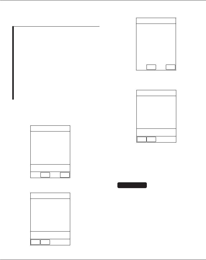
To allow changes to System Configuration parameters:
1. Hold OPTIONS key at power up.
System Config - Module 1 of 2
Factory default: |
Yes |
Shared Infusion Settings
PC Unit
Pump Module
SPO2 Module
>Select an Option
or EXIT
EXIT |
PAGE |
|
DOWN |
||
|
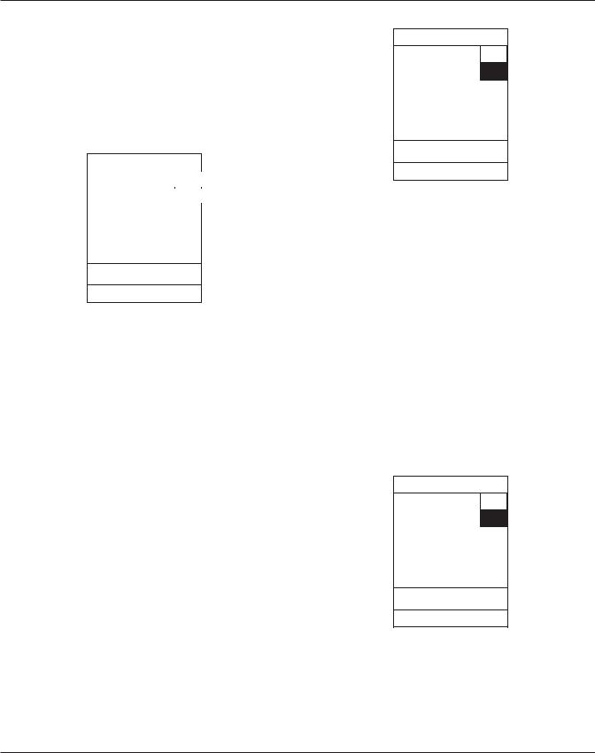
2.Press Factory default soft key.
3.Press No soft key.
System Configuration
Factory Default |
Yes |
|
|
Settings? |
No |
|
|
|
|
Selection of Yes sets all System Configuration parameters to the factory default setting.
EXIT
4.To accept change, press EXIT soft key.
•Option setting changes and main
System Config - Module screen displays.
2.4CONFIGURATION SETUP - SYRINGE MODULE
NOTES:
•Pressing the EXIT soft key while in a
System Config - Module screen immediately powers the system down, with no “Powering Down” display.
•Pressing the EXIT soft key while in a
System Config - Syringe screen returns the display to the main System Config - Module screen.
2-2 Alaris® Syringe Module (8110 Series)
Alaris® PCA Module (8120 Series)
Technical Service Manual
CHECKOUT AND CONFIGURATION
2.4CONFIGURATION SETUP - SYRINGE MODULE (Continued)
NOTES: (Continued)
•Pressing the CONFIRM soft key while in a System Configuration option screen:
♦accepts existing setting or setting change
♦displays next option setting screen (if applicable) or returns display to System Config - Syringe screen
•Pressing the PC Unit CANCEL key while in a System Configuration option screen:
♦leaves setting unchanged
♦returns display to System Config - Syringe screen
To access System Configuration options: 1. Hold OPTIONS key at power up.
System Config - Module 1 of 2
Factory default: No
Shared Infusion Settings
PC Unit
Pump Module
SPO2 Module
>Select an Option
or EXIT
EXIT |
PAGE |
|
DOWN |
||
|
2. Press PAGE DOWN soft key.
System Config - Module 2 of 2
Syringe Module
EtCO2 Module
>Select an Option
or EXIT
PAGE EXIT
UP
3. Press Syringe Module soft key.
System Config - Syringe 1 of 2
All Mode: |
Disabled |
|
Auto Pressure: |
Disabled |
|
Back Off: |
Disabled |
|
Fast Start: |
Disabled |
|
KVO: |
Disabled |
|
|
|
|
>Select an Option |
|
|
or EXIT |
|
|
EXIT |
PAGE |
|
DOWN |
||
|
4.To view additional options, press PAGE DOWN soft key.
System Config - Syringe 2 of 2
Max rate: |
999 mL/h |
Near End: |
Disabled |
Pressure limit-Disc:1000 mmHg
Pressure limit-NoDisc: Med
Priming: Disabled
>Select an Option
or EXIT
PAGE EXIT
UP
2.4.1All Mode
Enabling All mode allows ALL to be selected as the volume to be infused (VTBI), to deliver the entire contents of the syringe.
CAUTION
If KVO and ALL modes are both enabled, the ALL mode will not deliver the entire syringe contents. A small percentage of the syringe contents will be left available for KVO operation.
Alaris® Syringe Module (8110 Series) |
2-3 |
Alaris® PCA Module (8120 Series)
Technical Service Manual
CHECKOUT AND CONFIGURATION
2.4CONFIGURATION SETUP - SYRINGE MODULE (Continued)
2.4.1All Mode (Continued)
1.After accessing System Config - Syringe options display, press All Mode soft key.
System Configuration- Pump 2 of 3
- Syringe
All mode |
Enable |
|
|
|
Disable |
|
|
Allows use of the
All mode feature.
2.To change option setting, press soft key next to applicable option (Enable or
Disable).
•Option setting changes and System Config - Syringe page 1 displays.
2.4.2Auto Pressure
Enabling Auto Pressure allows the Auto Pressure option to be displayed in the Pressure Limit screen when a pressure sensing disc is in use. Auto Pressure automatically sets the alarm limit for a shorter time to alarm, as follows:
•If current pressure is 100 mmHg or less, system adds 30 mmHg to current pressure, to create a new alarm limit.
•If current pressure is greater than
100 mmHg, system adds 30% to current pressure, to create a new alarm limit.
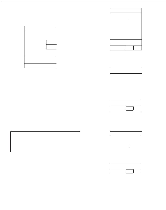
1.After accessing System Config - Syringe options display, press Auto Pressure soft key.
System Configuration - Syringe
Enable
Auto Pressure
Disable
Allows use of the auto pressure feature.
2.To change option setting, press soft key next to applicable option (Enable or
Disable).
•Option setting changes and System Config - Syringe page 1 displays.
2.4.3Back Off
When Back Off mode is enabled and a pressure sensing disc is in use, the motor reverses plunger movement during an occlusion until the pressure returns to preocclusion levels, automatically reducing bolus flow.
1.After accessing System Config - Syringe options display, press Back Off soft key.
System Configuration - Syringe
Enable
Back Off mode
Disable
Allows use of the back off feature.
2.To change option setting, press soft key next to applicable option (Enable or
Disable).
•Option setting changes and System Config - Syringe page 1 displays.
2-4 Alaris® Syringe Module (8110 Series)
Alaris® PCA Module (8120 Series)
Technical Service Manual
CHECKOUT AND CONFIGURATION
2.4CONFIGURATION SETUP - SYRINGE MODULE (Continued)
2.4.4Fast Start
When Fast Start mode is enabled and a pressure sensing disc is in use, the instrument runs at an increased rate when an infusion starts, taking up any slack in the drive mechanism.
1.After accessing System Config - Syringe options display, press Fast Start soft key.
System Configuration - Syringe
Enable
Fast Start mode
Disable
Allows use of the fast start feature.
2.To change option setting, press soft key next to applicable option (Enable or
Disable).
•Option setting changes and System Config - Syringe page 1 displays.
2.4.5KVO
Enabling KVO allows some infusions to automatically switch into KVO (keep vein open) mode upon completion. The KVO option setting cannot be changed after the instrument is powered on and a profile selected.
CAUTION
If KVO and ALL modes are both enabled, the ALL mode does not deliver the entire syringe contents, leaving a small percentage of the syringe contents available for KVO operation.
NOTE: In the following procedure, the KVO option is changed to Enable. Changing the option setting to Disable, disables the
Change Rate and Change Volume soft keys, as displayed in step 1.
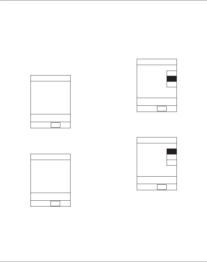
1.After accessing System Config - Syringe options display, press KVO soft key.
System Configuration - Syringe
KVO |
|
Enable |
|
|
|||
Rate: |
Disable |
||
1 mL/h |
|
||
Change |
|||
|
|
||
Volume: |
Rate |
||
|
|||
2% |
|
Change |
|
|
Volume |
||
|
|
||
|
|
|
|
Allows use of the KVO feature.
CONFIRM
2.To change option setting, press soft key next to applicable option (Enable or
Disable).
System Configuration - Syringe
KVO |
Enable |
|
|
||
Rate: |
Disable |
|
|
||
1 mL/h |
|
|
Change |
||
|
||
Volume: |
Rate |
|
|
||
2% |
Change |
|
Volume |
||
|
||
|
|
Allows use of the KVO feature.
CONFIRM
Alaris® Syringe Module (8110 Series) |
2-5 |
Alaris® PCA Module (8120 Series)
Technical Service Manual

CHECKOUT AND CONFIGURATION
2.4CONFIGURATION SETUP - SYRINGE MODULE (Continued)
2.4.5KVO (Continued)
3.To change KVO rate, press Change Rate soft key and enter new rate (0.01 to 2.5 mL/h in 0.01 mL/h increments).
NOTE: Flow rates less than 0.01 mL/h are available only with a 1 cc syringe. For larger syringes, the lower limit adjusts to 0.1 mL/h.
2.4.6Max rate
The Maximum rate value identifies the maximum rate at which a bolus dose can be delivered. When the Max Rate option is selected during bolus dose programming, the bolus is delivered at the maximum rate for an automatically calculated duration.
1.After accessing System Config - Syringe options display, page 2, press Max rate soft key.
System Configuration - Syringe
KVO |
Enable |
||
|
|||
Rate: |
Disable |
||
|
|||
_ 2 mL/h |
|
||
Change |
|||
|
|
||
Volume: |
|
Rate |
|
2% |
|
Change |
|
|
Volume |
||
|
|
||
|
|
|
|
Allows use of the KVO feature.
System Configuration - Syringe
Maximum rate adjustment
Maximum |
|
|
Change |
||
rate: |
||
Value |
||
999 mL/h |
|
|
Confirm |
||
|
||
|
|
CONFIRM
4.To change KVO volume, press Change Volume soft key and enter new volume level (0.5 to 5%).
System Configuration - Syringe
KVO |
Enable |
||
|
|||
Rate: |
Disable |
||
|
|||
2 mL/h |
|
|
|
|
Change |
||
|
|
||
Volume: |
Rate |
||
|
|||
Change |
|||
_5% |
|
||
|
|
Volume |
|
Allows use of the KVO feature.
CONFIRM
5.To accept changes(s), press CONFIRM soft key.
• Settings change and System Config - Syringe page 1 displays.
2.To change maximum rate, press Change Value soft key and enter new rate (0.1 to 99.9 mL/h in 0.1 mL/h increments; 100 to 999 mL/h in 1 mL/h increments).
System Configuration - Syringe
Maximum rate adjustment
Maximum |
|
|
Change |
||
rate: |
||
Value |
||
_ _ _ mL/h |
|
-- Continued Next Page --
2-6 Alaris® Syringe Module (8110 Series)
Alaris® PCA Module (8120 Series)
Technical Service Manual
CHECKOUT AND CONFIGURATION
2.4CONFIGURATION SETUP - SYRINGE MODULE (Continued)
2.4.6Max rate (Continued)
System Configuration - Syringe
Maximum rate adjustment
Maximum |
|
Change |
|
rate: |
|||
Value |
|||
|
|
|
|
99.9 mL/h |
Confirm |
|
3.To accept change, press Confirm soft key.
• Setting changes and System Config - Syringe page 2 displays.
2.4.7Near End
Enabling Near-End-of-Infusion (NEOI) allows an alert to be set from 1 to
60 minutes before the infusion is complete. The alert occurs at the configured time or when 25% of the VTBI remains, whichever occurs later.
NOTE: In the following procedure, the Near End option is changed to Enable. Changing the option setting to Disable disables the Change Time soft key, as displayed in
step 1.
1.After accessing System Config - Syringe options display, page 2, press Near End soft key.
System Configuration - Syringe
|
Enable |
|
Near-End-of |
|
|
Infusion |
Disable |
|
Alert Time: |
|
|
Change |
||
2 min |
||
Time |
||
|
|
Allows use of the Near-End-of
Infusion feature. |
Disable |
|
CONFIRM
2.To change option setting, press soft key next to applicable option (Enable or
Disable).
System Configuration - Syringe
Near-End-of |
Enable |
|
|
||
|
||
Infusion |
Disable |
|
Alert Time: |
|
|
Change |
||
2 min |
||
Time |
||
|
|
Allows use of the Near-End-of
Infusion feature. |
Disable |
|
CONFIRM
3.To change Alert Time, press Change Time soft key and enter new time
(1 to 60 minutes).
System Configuration - Syringe
|
|
Enable |
|
Near-End-of |
|
||
|
|||
Infusion |
Disable |
||
Alert Time: |
|
|
|
|
Change |
||
10 min |
|||
Time |
|||
|
|
||
Allows use of the Near-End-of |
|||
Infusion feature. |
Disable |
||
|
|
||
CONFIRM
4.To accept changes(s), press CONFIRM soft key.
• Settings change and System Config - Syringe page 2 displays.
Alaris® Syringe Module (8110 Series) |
2-7 |
Alaris® PCA Module (8120 Series)
Technical Service Manual
CHECKOUT AND CONFIGURATION
2.4CONFIGURATION SETUP - SYRINGE MODULE (Continued)
2.4.8Pressure Limit - Disc
This option allows setting an occlusion pressure point when a pressure sensing disc is in use.
1.After accessing System Config - Syringe options display, page 2, press
Pressure limit-Disc soft key.
System Configuration - Syringe
Pressure Limit Selection (disc present)
Current limit
1000 mmHg |
|
Change |
|
|
Value |
|
|
CONFIRM
2.To change pressure limit, press Change Value soft key and enter new limit (25 to 1000 mmHg in 1 mmHg increments).
System Configuration - Syringe
Pressure Limit Selection (disc present)
Current limit
_ 600 mmHg |
|
|
Change |
||
|
Value |
|
|
|
|
|
|
CONFIRM
3.To accept change, press CONFIRM soft key.
• Setting changes and System Config - Syringe page 2 displays.
2.4.9Pressure limit - No Disc
This option allows setting an occlusion pressure point when no pressure sensing disc is in use.
1.After accessing System Config - Syringe options display, page 2, press
Pressure limit-NoDisc soft key.
System Configuration - Syringe
Pressure Limit Selection (no disc)
Low
Med
High
CONFIRM
2.To change pressure limit (occlusion pressure set point), press applicable soft key (Low, Med, High).
System Configuration - Syringe
Pressure Limit Selection
(no disc)
Low
Med
High
CONFIRM
3.To accept change, press CONFIRM soft key.
• Setting changes and System Config - Syringe page 2 displays.
2-8 Alaris® Syringe Module (8110 Series)
Alaris® PCA Module (8120 Series)
Technical Service Manual
CHECKOUT AND CONFIGURATION
2.4CONFIGURATION SETUP - SYRINGE MODULE (Continued)
2.4.10 Priming
Enabling Priming mode allows a limited volume of fluid to be delivered to prime the administration set before connecting to a patient or following a syringe change. When priming, a single continuous press of the PRIME soft key delivers up to 2 mL of priming fluid.
1.After accessing System Config - Syringe options display, page 2, press Priming soft key.
System Configuration- Pump 2 of 3
- Syringe
Priming mode |
Enable |
|
|
|
Disable |
|
|
Allows use of the priming feature.
2.To change option setting, press soft key next to applicable option (Enable or
Disable).
•Option setting changes and System Config - Syringe page 2 displays.
2.5CONFIGURATION SETUP - SHARED INFUSION - PUMP AND SYRINGE MODULES
Refer to the 8000/8100 Series Technical Service Manual.
2.6CONFIGURATION OPTIONS AND DEFAULTS - PCA MODULE
NOTE: With the Profiles feature enabled, the settings are configured independently for each profile. A hospital-defined, bestpractice data set must be uploaded to enable the Profiles feature. Date and Time is a system setting and is the same in all profiles.
System Settings: Refer to the PC Unit section of the Alaris® System DFU.
PCA Module Settings: Refer to the PCA Module section of the Alaris® System DFU.
PCA Module Configuration Parameters:
Select system configuration settings for the PCA Module during data set development, then upload them as part of the data.
Alaris® Syringe Module (8110 Series) |
2-9 |
Alaris® PCA Module (8120 Series)
Technical Service Manual

CHECKOUT AND CONFIGURATION
T H I S PA G E
I N T E N T I O N A L LY
L E F T B L A N K
2-10 Alaris® Syringe Module (8110 Series)
Alaris® PCA Module (8120 Series)
Technical Service Manual
3 PREVENTIVE MAINTENANCE

Chapter 3 — PREVENTIVE MAINTENANCE
WARNING |
3.1 INTRODUCTION |
|
|
|
|
Failure to perform regular and preventive maintenance inspections may result in improper instrument operation.
Perform regular and preventive maintenance inspections to ensure that the Syringe and PCA Modules remain in good operating condition:
•Perform regular inspections before each use.
•Perform preventive maintenance inspections annually.
These requirements and guidelines are intended to complement the intent of Joint Commission on Accreditation of Healthcare Organizations (JCAHO) requirements.
3.2REGULAR AND PREVENTIVE MAINTENANCE INSPECTIONS, CALIBRATION
Use the Maintenance Software to perform calibration and preventive maintenance.
Contact CareFusion Technical Support for help obtaining or using Maintenance Software.
3.3CLEANING
Refer to the Alaris® System DFU.
Alaris® Syringe Module (8110 Series) |
3-1 |
Alaris® PCA Module (8120 Series)
Technical Service Manual

PREVENTIVE MAINTENANCE
T H I S PA G E
I N T E N T I O N A L LY
L E F T B L A N K
3-2 Alaris® Syringe Module (8110 Series)
Alaris® PCA Module (8120 Series)
Technical Service Manual
 Loading...