

Page 1
Alaris
Ricky Thomas
Specialist, TSC
Technical Support
July 24, 2009
®
System Maintenance
DIR 100000102142_00 CO 1065866 Page 1 of 64
© 2009 CareFusion Corporation or one of its subsidiaries. All rights reserved.
Page 2

®
Alaris
Introduction;
• Title: Webinar on Alaris® System Maintenance Software Fundamentals
• Length: Approximately 1 hour, and 45 minutes
• Target Audience: The experienced biomedical professional who will be involved in the repair and
routine maintenance of Alaris® System
• Take away: An understanding of the Alaris® System Maintenance, its basic interfacing features,
preventative maintenance procedures, software configuration procedures, and feel confident in
his/her ability to quickly ascertain the status of the system and affect any maintenance
System Maintenance
• Methods: Slide presentation, software demonstration, and visual demonstration interfacing with
instruments connected to software application.
• Prerequisite: Technical experience in the repair and maintenance of critical biomedical
instruments and systems. A clear understanding of personal computers and Microsoft Windows
Operating Systems
DIR 100000102142_00 CO 1065866 Page 2 of 64
© 2009 CareFusion Corporation or one of its subsidiaries. All rights reserved.
Page 3

®
Alaris
Agenda
– Introduction to Alaris® System Maintenance.
– Main Window; Overview
– Features of the Menu Bar / includes File, Options, and Help.
Options; Include Applications, and Database Settings as well as Export/Import and Migrate
MSW database.
• Establish software application functionality
• Creating and defining database definitions for retrieval reports
• Export/Import dialog
– Window menu tabs; Include Perform Maintenance, View Reports, and Configure Components.
• Basic overview tutorial with software demonstration.
• Create configuration packages (Network/Auto ID), and Task groups
• View report types, and running reports (also viewing log information).
System Maintenance
– Perform Maintenance demonstration.
– Network configuration setup (Optional for wireless customer).
DIR 100000102142_00 CO 1065866 Page 3 of 64
© 2009 CareFusion Corporation or one of its subsidiaries. All rights reserved.
Page 4

®
Alaris
Objective;
• Alaris® System Maintenance which is a PC–based application built for the biomedical engineer to
streamline Alaris® System configuration and perform preventative maintenance activities.
• Maintain Alaris® PC Units model 8000/8015 and attached modules.
• Run check-in procedures.
• Perform preventive maintenance
• Set and check preventive maintenance reminder dates.
• Diagnose, troubleshoot and repair instruments.
• Calibrate modules.
• Transfer Data Set.
• Transfer Network Configuration.
• Download and view instrument logs.
System Maintenance
Note; Alaris® System Maintenance software replaces Maintenance Software and Flash Tool for the
Alaris
DIR 100000102142_00 CO 1065866 Page 4 of 64
© 2009 CareFusion Corporation or one of its subsidiaries. All rights reserved.
®
System. In addition, the software allows for transfer of Data Set, and download of CQI Logs.
Page 5

®
Alaris
•The role of a the Biomedical Technicians will be?
System Maintenance
– Perform preventative maintenance using the Alaris
®
System Maintenance.
– Troubleshoot faults and perform repairs
– Verify and update module software versions using the Flash Tool Software
– Perform check-in verification on instruments returned from Alaris® repair depot
®
– Download CQI alerts from the Alaris
®
– Configure Alaris
PC Units to communicate over the wireless network (Alaris® System
PC Units
Maintenance)
®
– Transfer released Data Sets to the Alaris
PC Units
DIR 100000102142_00 CO 1065866 Page 5 of 64
© 2009 CareFusion Corporation or one of its subsidiaries. All rights reserved.
Page 6
General Contact Information
Customer Advocacy
For clinical and technical questions, feedback, and troubleshooting assistance.
Phone, toll-free, within the United States and Canada: (800) 888-876-4287, option 1, 1, option 3
E-Mail: CustomerFeedback@alarismed.com
For details on the Factory Depot Repair Service Agreement, please contact an
Cardinal Health Service Contract Specialist; Susan Kinzer @ (Phone) 858-617-4921, ext.
74921, Susan.Kinzer@cardinalhealth.com
x74744; (fax) 858-617-5184 elizabeth.boyd@cardinalhealth.com
Technical Support - North America
For technical information related to maintenance procedures and service manual support.
Direct Dial: 888-812-3229 (Technical Support Department)
Toll-free: (888) 876-4CTS (4287), Options 1, 1, 2, 1 (@ prompts)
, Sr. Contract Admin; Elizabeth Boyd @ (Phone) 858-617-4744,
United States:
Canada:
Phone, Toll-free:
Eastern: (8 00) 908-9918
Western: (800) 908-9919
For more detailed information, refer to the “Service Information” section of this document.
DIR 100000102142_00 CO 1065866 Page 6 of 64
© 2009 CareFusion Corporation or one of its subsidiaries. All rights reserved.
Page 7

Alaris
®
System Maintenance
• Briefly, any questions before we start
with Alaris
®
System Maintenance
software demo.
DIR 100000102142_00 CO 1065866 Page 7 of 64
© 2009 CareFusion Corporation or one of its subsidiaries. All rights reserved.
Page 8
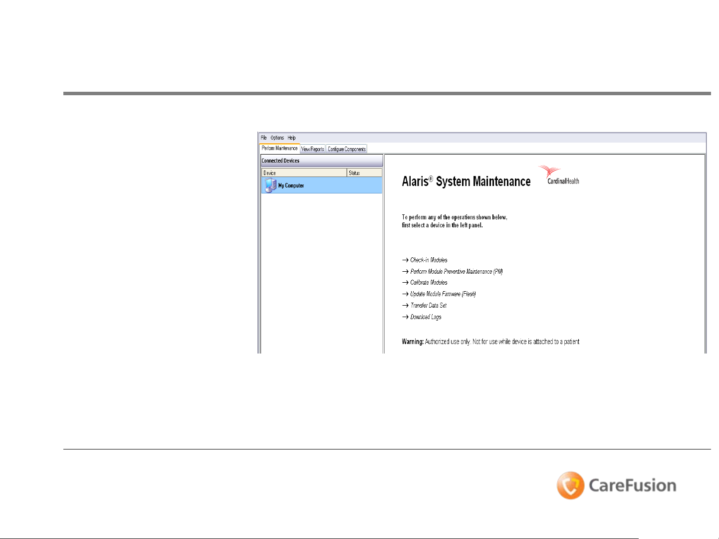
®
Alaris
ASM version 9 Maintenance
software allows routine
maintenance to be performed
on the Alaris® System
hardware.
The System Maintenance kit
includes.
– System Maintenance
CD-Rom
– Serial cable
System Maintenance
Next we’ll look at the
differences between
the Alaris
Maintenance (ASM),
software versus the
Maintenance Software
(MSW)
DIR 100000102142_00 CO 1065866 Page 8 of 64
© 2009 CareFusion Corporation or one of its subsidiaries. All rights reserved.
®
System
Page 9
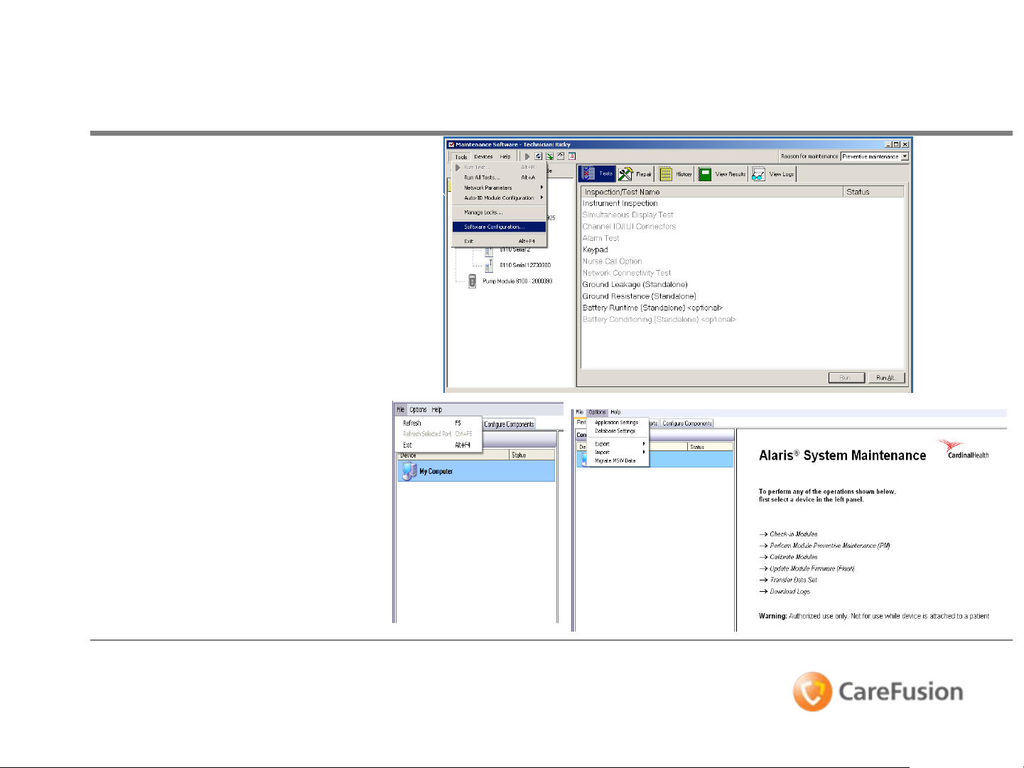
®
Alaris
• Maintenance Software
version 5,6,7, and 8 have
visible differences in the
format.
• Select menu bar to
choose Tools, Devices,
and Help.
• Alaris® System
Maintenance main
window appears.
• Select menu bar to
choose File (refresh ports
and/or exit), Options
(application/database
settings, export/import,
and migrate MSW files.
System Maintenance vs. MSW
• Help displays version and
copyright information.
DIR 100000102142_00 CO 1065866 Page 9 of 64
© 2009 CareFusion Corporation or one of its subsidiaries. All rights reserved.
Page 10
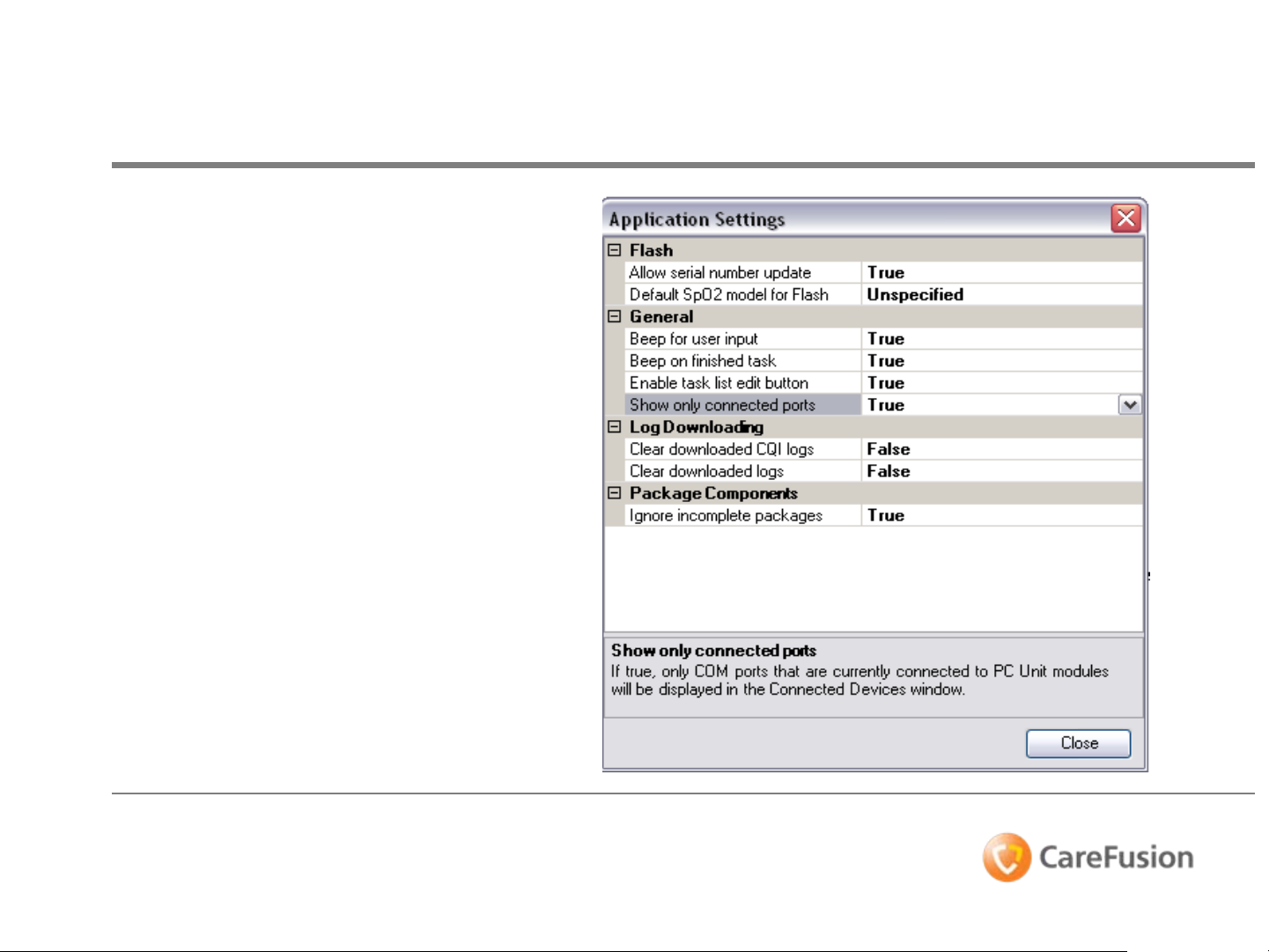
Application Settings
• Select menu bar to choose
OPTIONS.
• Select Application Settings
from the drop-down.
The Application Settings
dialog box is used to
configure the available
application options for ASM.
DIR 100000102142_00 CO 1065866 Page 10 of 64
© 2009 CareFusion Corporation or one of its subsidiaries. All rights reserved.
Page 11
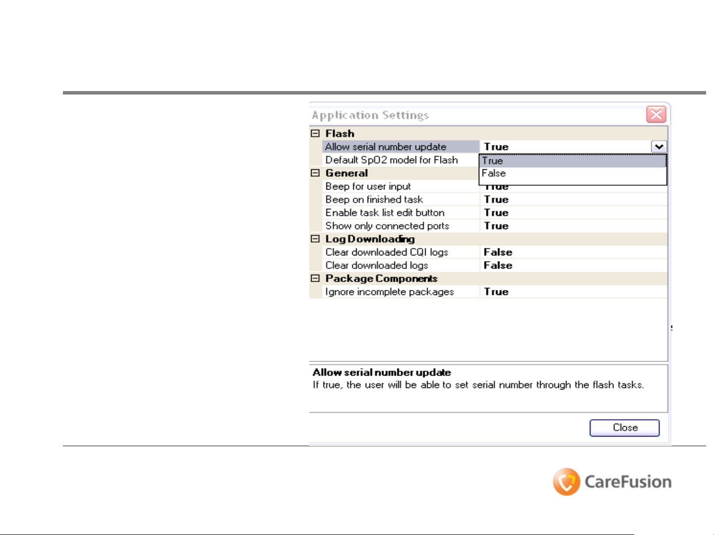
Application Settings
• Select “Allow serial number
update”, in dialog box.
• Click dropdown arrow to
select True or False next to
the setting your wish to
change.
• In the Description field,
describes “If true, the user
will be able to set the serial
number through the Flash
Tasks”.
DIR 100000102142_00 CO 1065866 Page 11 of 64
© 2009 CareFusion Corporation or one of its subsidiaries. All rights reserved.
Page 12
Application Settings
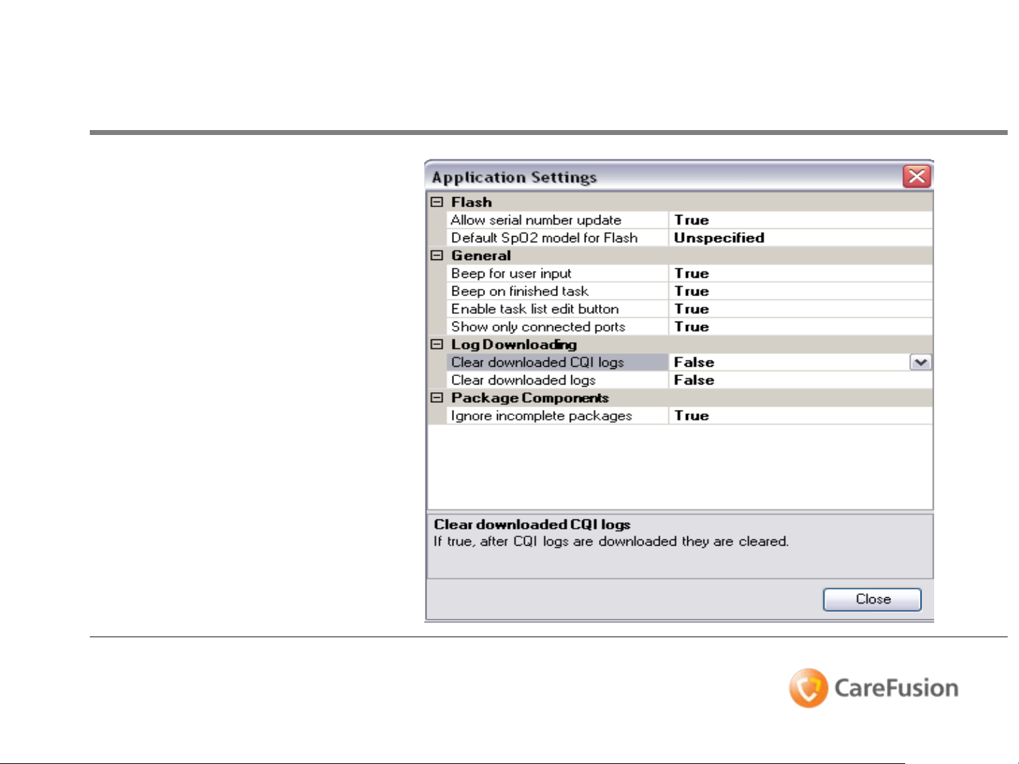
• Select “Clear downloaded
CQI logs”, in dialog box.
• Click dropdown arrow to
select True or False next to
the setting your wish to
change.
• In the Description field,
describes “If true, CQI logs
will be cleared from
connected devices after
download”.
DIR 100000102142_00 CO 1065866 Page 12 of 64
© 2009 CareFusion Corporation or one of its subsidiaries. All rights reserved.
Page 13

Application Settings Summary
• In the Applications Settings dialog box, which
allows for users to configure the available
application options for the software response.
DIR 100000102142_00 CO 1065866 Page 13 of 64
© 2009 CareFusion Corporation or one of its subsidiaries. All rights reserved.
Page 14
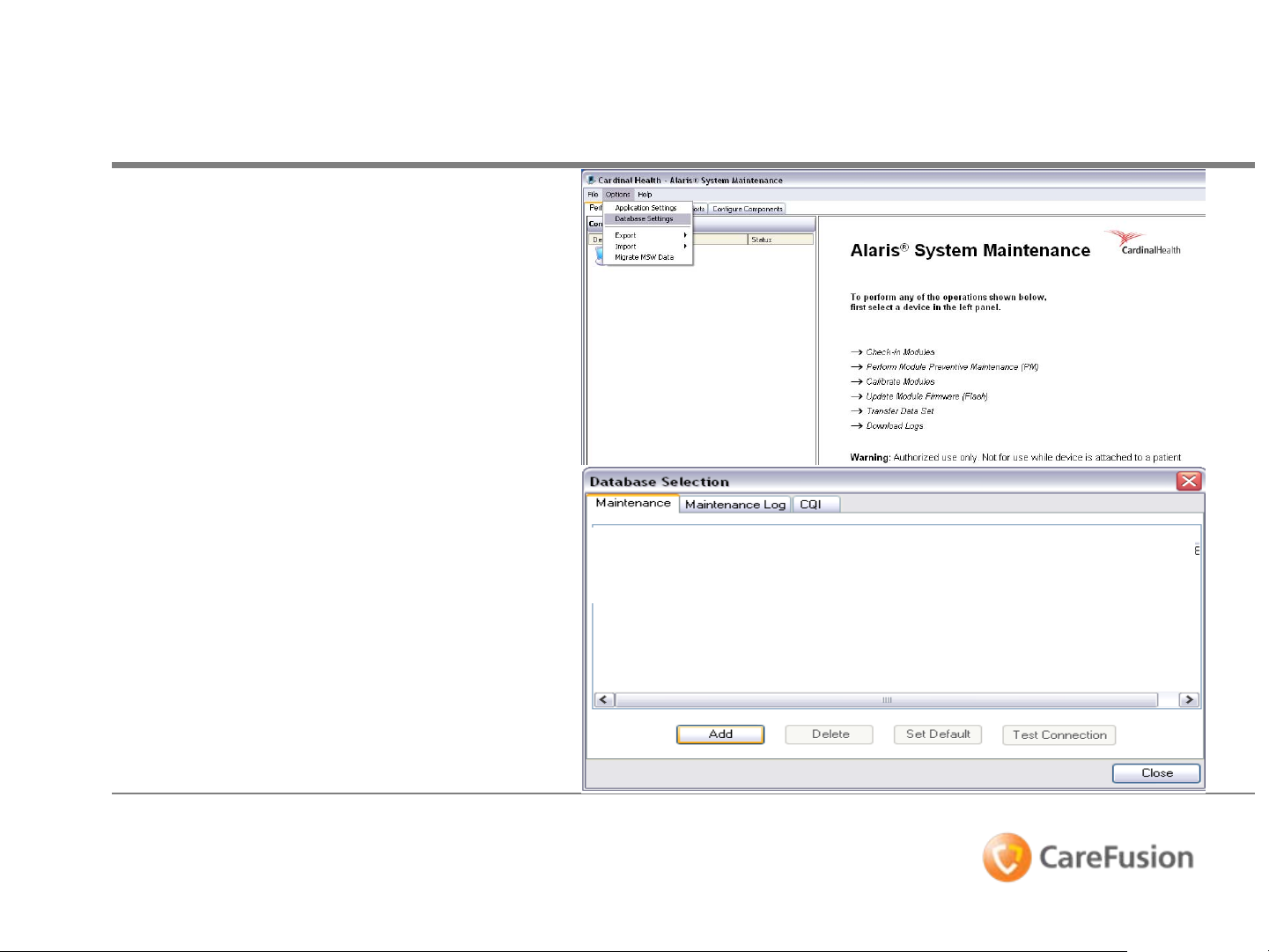
Database Settings
• Select menu bar to choose
OPTIONS.
• Select Database Settings from
the drop-down.
The Database Selection dialog
box will open. Defined databases
are Maintenance, Maintenance
Log, and CQI database (Tabs in
window).
• Select Add.
DIR 100000102142_00 CO 1065866 Page 14 of 64
© 2009 CareFusion Corporation or one of its subsidiaries. All rights reserved.
Page 15
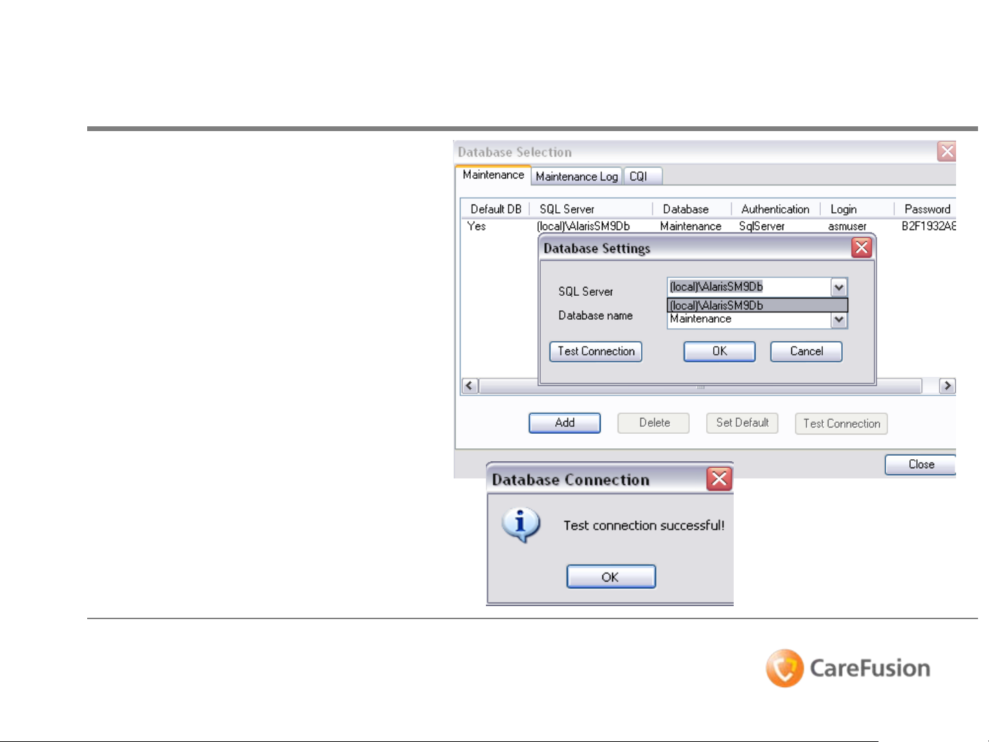
Database Settings
• Click dropdown arrow to select
SQL Server (and/or type name
of database in field).
• Select a Database name on SQL
Server.
• Test the connection with the
server (if successful, select OK).
• Select OK to save the definition.
DIR 100000102142_00 CO 1065866 Page 15 of 64
© 2009 CareFusion Corporation or one of its subsidiaries. All rights reserved.
Page 16
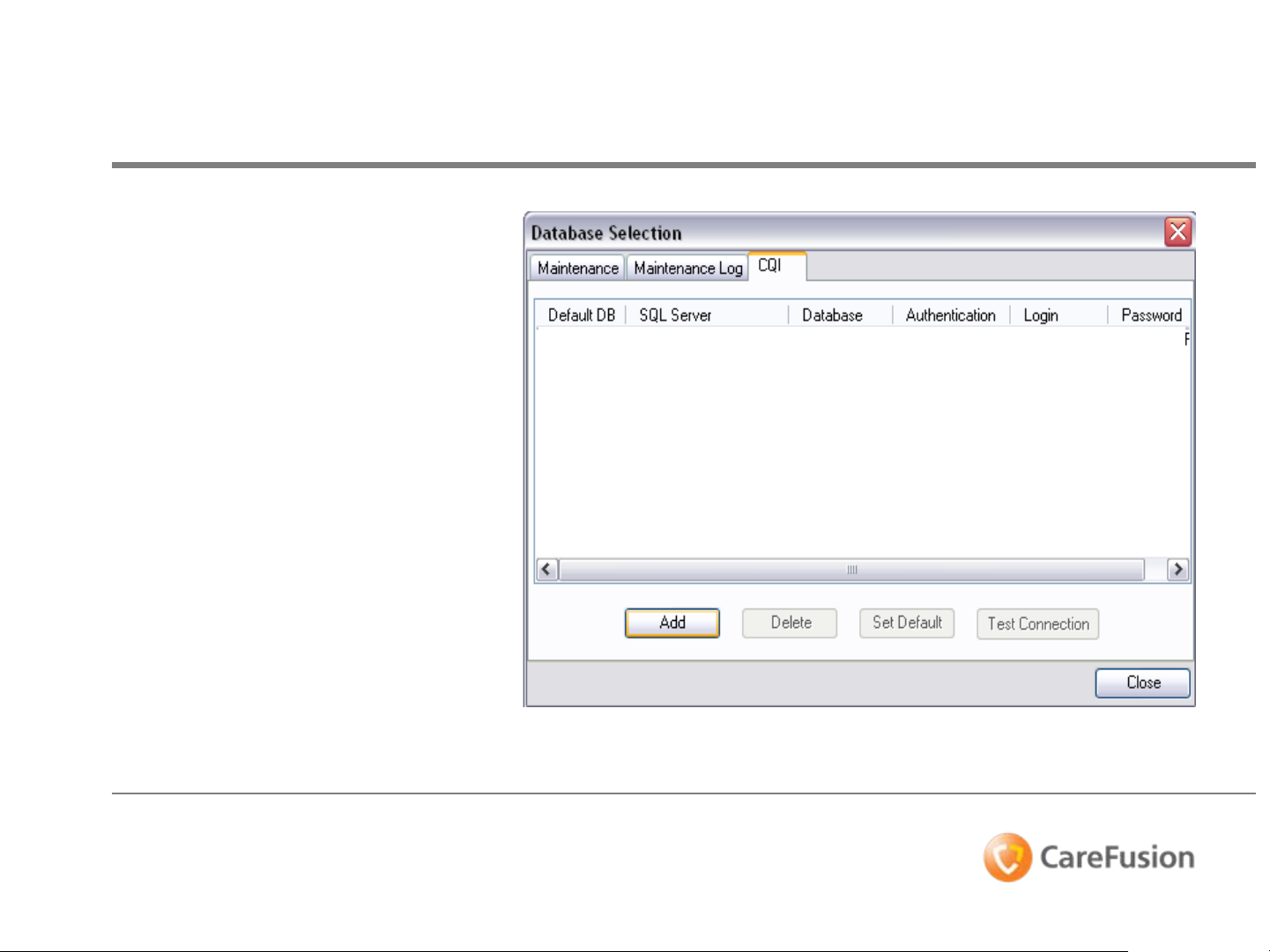
Database Settings
• Select the CQI tab.
• The Database Selection dialog
box will open. Defined
database CQI database (Tabs
in window). Each definition
contains server name and
authentication for the
databases.
• Select Add.
DIR 100000102142_00 CO 1065866 Page 16 of 64
© 2009 CareFusion Corporation or one of its subsidiaries. All rights reserved.
Page 17
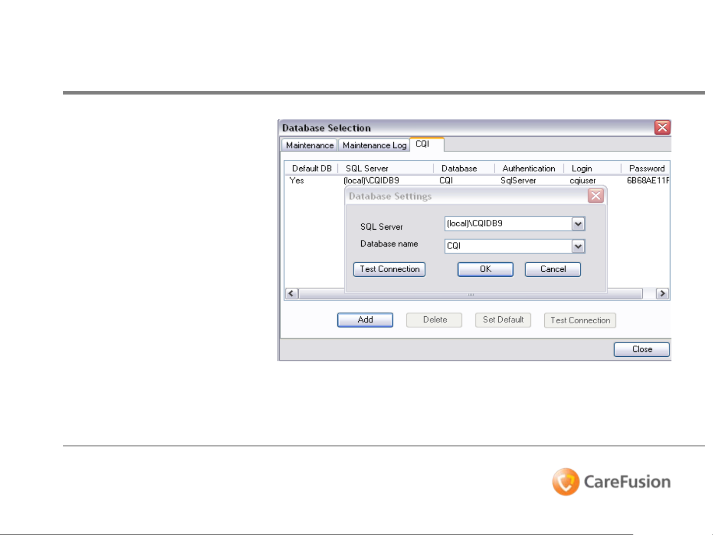
Database Settings
• The Database Selection
dialog box will display.
• Click dropdown arrow to
select SQL Server.
• Select a Database name on
SQL Server.
• Test the connection with the
server.
• Select OK to save the
definition.
DIR 100000102142_00 CO 1065866 Page 17 of 64
© 2009 CareFusion Corporation or one of its subsidiaries. All rights reserved.
Page 18

Database Settings Summary
• We’ve just reviewed multiple database definitions that defined
for the three System Maintenance databases (Maintenance
database, Maintenance Log database, CQI database).
• Learned how to test connections of databases, as well as
establish database.
• Each definition contains server name and authentication for the
databases.
DIR 100000102142_00 CO 1065866 Page 18 of 64
© 2009 CareFusion Corporation or one of its subsidiaries. All rights reserved.
Page 19
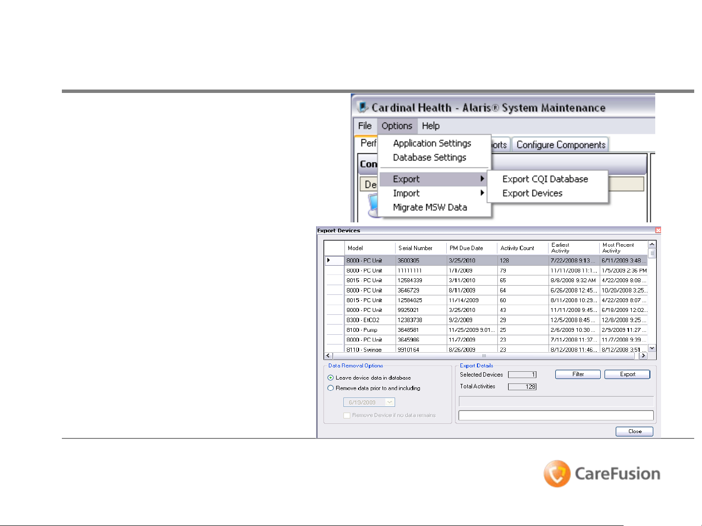
Exporting Devices
• Select menu bar to choose
OPTIONS.
• Select Export devices from
the drop-down.
The Export Devices dialog
box will open. Allowing for
Data Removal Options, and
Export Details.
DIR 100000102142_00 CO 1065866 Page 19 of 64
© 2009 CareFusion Corporation or one of its subsidiaries. All rights reserved.
Page 20
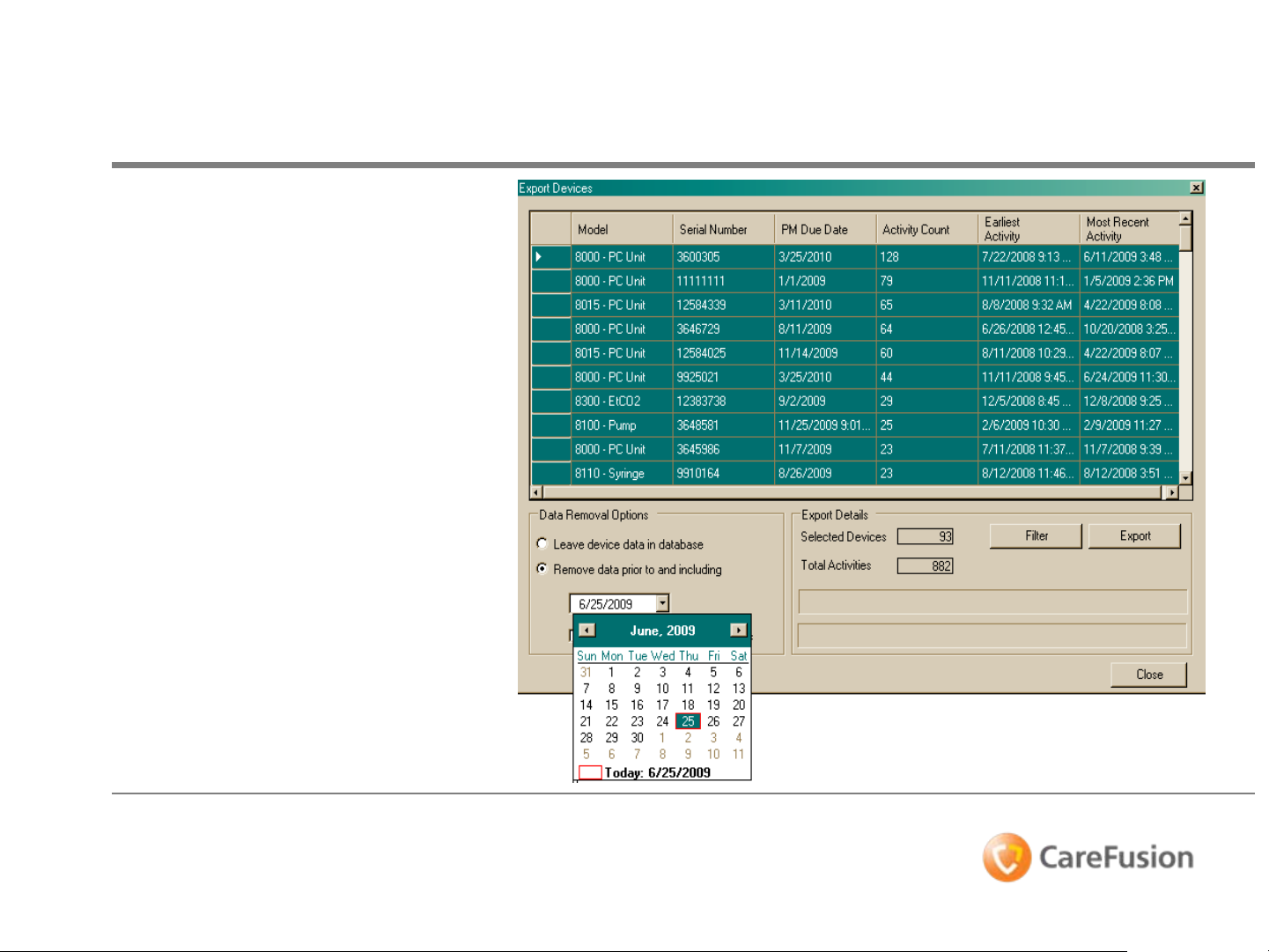
Exporting Devices
• Select individual devices
by clicking on line item
column.
• Click and drag to select
group of devices.
• Click upper left box to
highlight all devices in
database.
• Click Data Removal
Options.
• Select “Remove data
prior to and including”, to
enter a date range for
content selection.
DIR 100000102142_00 CO 1065866 Page 20 of 64
© 2009 CareFusion Corporation or one of its subsidiaries. All rights reserved.
Page 21

Exporting Devices
• Click Filter
• Click on Models checkbox
(left), to display only
8000-PC Units.
Device Filter allows to
select specific devices
to display in dialog box
for Export Devices.
DIR 100000102142_00 CO 1065866 Page 21 of 64
© 2009 CareFusion Corporation or one of its subsidiaries. All rights reserved.
Page 22

Exporting Devices
• Export Devices now shows 128
Total Activities for the model
8000-PC Units in database to be
selected.
Note:
Device Filter allows user to
select specific devices to display
in Export Devices dialog box.
• Select Export
DIR 100000102142_00 CO 1065866 Page 22 of 64
© 2009 CareFusion Corporation or one of its subsidiaries. All rights reserved.
Page 23

Exporting Devices
• Select and/or create a file
for the Exporting database
information.
• Select OK
DIR 100000102142_00 CO 1065866 Page 23 of 64
© 2009 CareFusion Corporation or one of its subsidiaries. All rights reserved.
Page 24

Exporting Devices
• Exporting information will now
be stored in this folder/file.
“Please remember name of file
created”.
• Status indicator bar in dialog
box will display Export has
completed successfully.
• Once transfer is completed, the
file is ready to be transferred
to another PC system, and/or
location.
DIR 100000102142_00 CO 1065866 Page 24 of 64
© 2009 CareFusion Corporation or one of its subsidiaries. All rights reserved.
Page 25

Exporting Devices Summary
• Exporting information allows export of the CQI database as well as the
Export Devices information for all devices that have been connected to the
PC Unit.
• We’ve stepped through the processes. This also allows for users to
transport device information to other workstations.
DIR 100000102142_00 CO 1065866 Page 25 of 64
© 2009 CareFusion Corporation or one of its subsidiaries. All rights reserved.
Page 26

Importing Devices
• To Import, select Import
Devices from the drop down
menu under Options.
• Click on Import Devices.
• This will bring up the Import
Devices dialog box.
DIR 100000102142_00 CO 1065866 Page 26 of 64
© 2009 CareFusion Corporation or one of its subsidiaries. All rights reserved.
Page 27

Importing Devices
• Click on Open File.
• In the pop-up window,
please select the Export
File created, and/or
received.
• Double-click on file, or click
file and select Open.
DIR 100000102142_00 CO 1065866 Page 27 of 64
© 2009 CareFusion Corporation or one of its subsidiaries. All rights reserved.
Page 28

Importing Devices
• The Import Devices dialog box displays the
Model and Serial Number of the devices in
file.
• Click on the Import # device button to start
import process.
• Data is imported into the selected database.
• Status indicator bar in dialog box will display
Import has completed successfully.
• Select Close.
DIR 100000102142_00 CO 1065866 Page 28 of 64
© 2009 CareFusion Corporation or one of its subsidiaries. All rights reserved.
Page 29

Migrate Data
• To transfer existing version
8 Database, select Migrate
MSW Data from the drop
down menu under Options.
• The Database Selection
dialog box will open.
DIR 100000102142_00 CO 1065866 Page 29 of 64
© 2009 CareFusion Corporation or one of its subsidiaries. All rights reserved.
Page 30

• The Database Selection
dialog box will display.
• Click a Database name on
SQL Server.
• Test the connection with the
server (optional).
• Select Migrate to transfer
data into database.
Migrate Data
DIR 100000102142_00 CO 1065866 Page 30 of 64
© 2009 CareFusion Corporation or one of its subsidiaries. All rights reserved.
Page 31

Importing & Migrate Devices
• Importing information allows Import of the CQI database as well as the
Import Devices information from other workstations.
• We’ve stepped through the processes. This also allows for users to
transport and/or transfer device information to other workstations.
• This process enables users to create reports from device information
received.
• In migrating a version 8 database, customer does not lose existing data
from previous software.
DIR 100000102142_00 CO 1065866 Page 31 of 64
© 2009 CareFusion Corporation or one of its subsidiaries. All rights reserved.
Page 32

Configure Components Tab
• Select the Configure Components tab
from main window, to add a New
configuration package to the list.
• One Configuration Package is
designated as the active package.
• Select the Configuration Packages
item and click New, or right-click the
Configuration Packages item and
select Add New Package from the
pop-up menu.
DIR 100000102142_00 CO 1065866 Page 32 of 64
© 2009 CareFusion Corporation or one of its subsidiaries. All rights reserved.
Page 33

Configure Packages
• Complete the Component
Details dialog box:
Name: Give the configuration
package a unique name.
Date: Select a creation date
(defaults to today’s date).
Author: Name of person
creating configuration package.
Description: A description for
configuration package.
Accept any changes in the
selected configuration package
by clicking the Accept Changes
button.
Note;
**This process can be
used for a non-wireless
account.
DIR 100000102142_00 CO 1065866 Page 33 of 64
© 2009 CareFusion Corporation or one of its subsidiaries. All rights reserved.
Page 34

Configure Components
• Accept any changes in the
selected configuration
package by clicking the
Accept Changes button.
Note:
The imported data will
overwrite any data already
in the selected
configuration package.
When importing, you can
only import configuration
data to overwrite of the
same type in the selected
configuration package.
DIR 100000102142_00 CO 1065866 Page 34 of 64
© 2009 CareFusion Corporation or one of its subsidiaries. All rights reserved.
Page 35

Auto ID Configurations
• Access Auto ID settings
under desired Configuration
Package, and use
Component Details pane on
the right to define Auto-ID
configuration.
• Select ID Type for Patient
and Clinician fields radio
buttons, to edit or define its
related ID Locators and ID
Format (input fields below).
• ID Format selects rule for
parsing corresponding data.
• ID Locators sets the
validation for the extracted
data from a barcode label.
Note; ID Locators rule cannot be
the same for Patient, or Clinician
ID.
DIR 100000102142_00 CO 1065866 Page 35 of 64
© 2009 CareFusion Corporation or one of its subsidiaries. All rights reserved.
Page 36

• The Description and
Example fields
display information to
explain the selected
rule.
• Click on the Accept
Changes button to
save edits to the
configuration package.
Auto ID
DIR 100000102142_00 CO 1065866 Page 36 of 64
© 2009 CareFusion Corporation or one of its subsidiaries. All rights reserved.
Page 37

• Access Firmware Files
under desired
Configuration Package,
and use Component
Details pane on the right
dialog box to identify the
Released Manifest File for
upload to the Alaris® PC
Unit and modules.
• Use the Browse button to
locate and find the
correct xml file to be
used to update the
Alaris® System.
Firmware Files
DIR 100000102142_00 CO 1065866 Page 37 of 64
© 2009 CareFusion Corporation or one of its subsidiaries. All rights reserved.
Page 38

• Firmware Files; Used by
individual flash tasks that
updates the firmware on the
PC unit and modules.
• Manifest files identify
firmware file to use for
updating the Alaris® PC unit
and modules, and contains
settings on how to apply
update to specific modules.
Firmware Files
DIR 100000102142_00 CO 1065866 Page 38 of 64
© 2009 CareFusion Corporation or one of its subsidiaries. All rights reserved.
Page 39

Firmware Files
• Open drop-down list
• Select options from the drop-
down list next to each applicable
device, to select what should
happen when a PC unit or
module is flashed with contents
of the Release Manifest File.
• Double-click on file, or click file
and select Open.
DIR 100000102142_00 CO 1065866 Page 39 of 64
© 2009 CareFusion Corporation or one of its subsidiaries. All rights reserved.
Page 40

• Always: Always
overwrite contents of
device with content from
the Release Manifest File.
• Newer Version: Only
overwrites contents of
device when the Release
Manifest File contains a
newer version than that
already existing on the
device.
• Never: Do not update
device with the Release
Manifest File.
Firmware Files
• Select Accept Changes to
save edits.
DIR 100000102142_00 CO 1065866 Page 40 of 64
© 2009 CareFusion Corporation or one of its subsidiaries. All rights reserved.
Page 41

• Access Data Set File
under desired
Configuration Package,
and use Component
Details pane on the
right dialog box to
identify Data Set.
• Use Browse to select
the file on the PC
workstation.
Data Set Files
DIR 100000102142_00 CO 1065866 Page 41 of 64
© 2009 CareFusion Corporation or one of its subsidiaries. All rights reserved.
Page 42

Data Set Files
• Use the Open dialog box drop-
down to select the Guardrails
data set .GRE file type for
transfer to the PC unit.
®
DIR 100000102142_00 CO 1065866 Page 42 of 64
© 2009 CareFusion Corporation or one of its subsidiaries. All rights reserved.
Page 43

Data Set Files
• In the Open pop-up window,
please select the Data Set
File created, and/or received.
• Double-click on file, or click
file and select Open.
• Data Set is now in the Alaris
System Maintenance
software application.
DIR 100000102142_00 CO 1065866 Page 43 of 64
© 2009 CareFusion Corporation or one of its subsidiaries. All rights reserved.
®
Page 44

• If you select Always
Overwrite Dataset,
whenever you upload a
data set to a Alaris® PC
unit, the old data set is
overwritten, even if data
sets are exactly the same.
If you do not select
Always Overwrite
Dataset, the old data set
is only overwritten if CRC
codes for the two data sets
are different.
• Click on the Accept
Changes button to save
edits to the configuration
package.
Data Set Files
DIR 100000102142_00 CO 1065866 Page 44 of 64
© 2009 CareFusion Corporation or one of its subsidiaries. All rights reserved.
Page 45

Configure Components Summary
• We create Configuration Packages which contain the configuration
®
settings that can be uploaded to the Alaris
as well as configuration information used solely on the Alaris
System Maintenance application running on service computer.
• You’ve learned some of the component details pane, and how user
input to dialog boxes or window pop-ups.
PC Unit and modules,
®
DIR 100000102142_00 CO 1065866 Page 45 of 64
© 2009 CareFusion Corporation or one of its subsidiaries. All rights reserved.
Page 46

Creating Task Groups:
1. Select the Configure
Components tab on the
System Maintenance main
window.
• Select the Task Groups
tab in the Components
window.
• Select a device type and
click New at the top of
the device type list, or
right-click on the device
and select New.
Task Groups
DIR 100000102142_00 CO 1065866 Page 46 of 64
© 2009 CareFusion Corporation or one of its subsidiaries. All rights reserved.
Page 47

• Enter a name for the
task group and select
Enter.
• The Component
Details pane appears.
• The Task group name
will be added to the list
of task groups in the
Components Task
Group
Task Groups
DIR 100000102142_00 CO 1065866 Page 47 of 64
© 2009 CareFusion Corporation or one of its subsidiaries. All rights reserved.
Page 48

1. If you wish to add a task,
select the task from the
Available Tasks list and
click Add to add it to the
Selected Tasks list for
the device.
2. If you wish to remove a
task, select the task in the
Selected Tasks list and
click Remove to remove it
from the list.
3. Continue selecting tasks
until you have collected all
the needed tasks.
4. Use the up and down
arrows to change the list
order, if required.
Task Groups
5. Select Save to save
changes.
DIR 100000102142_00 CO 1065866 Page 48 of 64
© 2009 CareFusion Corporation or one of its subsidiaries. All rights reserved.
Page 49

Task Groups Summary
• Note: Custom Task Groups can be defined and then added to the Task list. You
cannot edit the standard task groups, which will always display in the Task list.
• In creating the Task Group, you are able to customize the tasks specific to
diagnose and/or perform maintenance.
• You’ve also seen shortcut for adding or removing a single task.
• Hint; You’ll find that Double-clicking a task in the Master Task List will immediately
add it to the list. Double-clicking in a task in the Current Task list will immediately
remove that task from the list.
DIR 100000102142_00 CO 1065866 Page 49 of 64
© 2009 CareFusion Corporation or one of its subsidiaries. All rights reserved.
Page 50

Maintenance reports
are available from data
stored in the System
Maintenance and/or
the Maintenance Log
databases.
To run reports from
the System
Maintenance database:
1. Select the View
Reports tab on the
System Maintenance
screen.
View Reports
2. Select report type in
the Reports pane.
DIR 100000102142_00 CO 1065866 Page 50 of 64
© 2009 CareFusion Corporation or one of its subsidiaries. All rights reserved.
Page 51

View Reports
3. Select devices by clicking on
the Select Devices button.
In the Device Selection
dialog box, you can use the
following techniques:
• Ctrl-click to select multiple
devices.
• Shift-click to select a range
of devices in the displayed
list.
• Select the Filter button to
select specific model numbers
or PM Due dates for display.
• Select the Serial Search to
display devices with serial
numbers starting with
number sequence entered.
4. Click Select.
DIR 100000102142_00 CO 1065866 Page 51 of 64
© 2009 CareFusion Corporation or one of its subsidiaries. All rights reserved.
Page 52

View Reports
5. If required, enter a start
and end date for the
report.
• The start date defaults to
the earliest entry in the
database and the end date
defaults to today’s date.
6. Click Create Report.
• The report generates and
displays on screen.
DIR 100000102142_00 CO 1065866 Page 52 of 64
© 2009 CareFusion Corporation or one of its subsidiaries. All rights reserved.
Page 53

View Reports Summary
• Now we’ve learned that a number of maintenance reports are available
from data stored in the System Maintenance and/or the Maintenance Log
databases.
• These would include Activity, Asset, Logs (Battery, Error, Event), PM Due,
and Test (Check-in, All, and PM).
DIR 100000102142_00 CO 1065866 Page 53 of 64
© 2009 CareFusion Corporation or one of its subsidiaries. All rights reserved.
Page 54

Perform Maintenance Demo
• At this opportunity, we will need to briefly step
out of the presentation as to demonstrate the
ASM software application.
• ASM demonstration will be followed by a
Networking demo for our networking customers.
• If you are not a wireless customer, the
Networking Demo is an optional item and not
mandatory to participate.
DIR 100000102142_00 CO 1065866 Page 54 of 64
© 2009 CareFusion Corporation or one of its subsidiaries. All rights reserved.
Page 55

Configuration Packages
To import a configuration package:
1. Select a configuration package
name in the Configuration
Packages list to highlight it.
2. Click Import or right-click on the
configuration package name and
select Import from the pop-up
menu.
• The Open dialog box displays.
Note;
Defining network profiles should
only be performed by Network
Administrator or other qualified
personnel.
DIR 100000102142_00 CO 1065866 Page 55 of 64
© 2009 CareFusion Corporation or one of its subsidiaries. All rights reserved.
Page 56

Configuration Packages
3. Browse to select a .cfg file to
import and select Open.
• Data is imported into the
selected configuration package.
4. Accept any changes in the
selected configuration package
by clicking Accept Changes.
DIR 100000102142_00 CO 1065866 Page 56 of 64
© 2009 CareFusion Corporation or one of its subsidiaries. All rights reserved.
Page 57

Create Network Profile
1. Right-click on the Network Settings for the
desired package, and select Add New
Network Profile.
Note; The Alaris® System Maintenance software
can define and save up to eight network
profiles on a PC unit.
Network Profiles
DIR 100000102142_00 CO 1065866 Page 57 of 64
© 2009 CareFusion Corporation or one of its subsidiaries. All rights reserved.
Page 58

Network Profiles
• The profile appears in the
Component Details pane.
• The Datalink tab allows you
to specify the wireless security
settings for this profile.
DIR 100000102142_00 CO 1065866 Page 58 of 64
© 2009 CareFusion Corporation or one of its subsidiaries. All rights reserved.
Page 59

Network Profiles
The Network tab allows you to
specify the Internet Protocol
(IP) information for connecting
to the Information Server.
1. Choose either Obtain an IP
Address Automatically, or
Use Static IP Address from
the drop-down list.
2. Choose either Obtain DNS
Server Address
Automatically, or Use Static
DNS IP Address from the
drop-down list.
DIR 100000102142_00 CO 1065866 Page 59 of 64
© 2009 CareFusion Corporation or one of its subsidiaries. All rights reserved.
Page 60

Network Profiles
The Server tab allows you to
specify the application-level
communication protocol
settings that will be used
between the PC unit and the
information server.
1. Choose DCMP application-level
communication protocol from
drop-down list.
2. Specify related information
from the following table.
3. Accept any changes in the
selected configuration package
by clicking Accept Changes.
DIR 100000102142_00 CO 1065866 Page 60 of 64
© 2009 CareFusion Corporation or one of its subsidiaries. All rights reserved.
Page 61

Importing Configuration Packages
To import a configuration
package:
1. Select a configuration
package name in the
Configuration Packages
list to highlight it.
2. Click Import or right-
click on the configuration
package name and select
Import from the pop-up
menu.
DIR 100000102142_00 CO 1065866 Page 61 of 64
© 2009 CareFusion Corporation or one of its subsidiaries. All rights reserved.
Page 62

Importing Configuration Packages
The Open dialog box displays.
1. Browse to select a .cfg file to
import and select Open.
2. Data is imported into selected
configuration package.
3. Accept any changes in the
selected configuration
package by clicking Accept
Changes.
DIR 100000102142_00 CO 1065866 Page 62 of 64
© 2009 CareFusion Corporation or one of its subsidiaries. All rights reserved.
Page 63

Configuration Packages Summary
• You’ve just seen examples of how Configuration Packages are setup.
• Users can now create tasks for the Transfer of Network Configuration.
• Add to note; Defining network parameter sets should only be performed
by the Network Administrator or other qualified personnel.
®
Alaris
Profiles on a PC Unit. These profiles are used when the PC Unit connects to
the network, allowing an institution to create a large network with multiple
System Maintenance can define and save up to eight (8), Network
access points. If PC Units are moved, it cycles through the available
profiles to find the optimum profile for that location.
DIR 100000102142_00 CO 1065866 Page 63 of 64
© 2009 CareFusion Corporation or one of its subsidiaries. All rights reserved.
Page 64

Thank You
DIR 100000102142_00 CO 1065866 Page 64 of 64
© 2009 CareFusion Corporation or one of its subsidiaries. All rights reserved.
 Loading...