

Page 1

Alaris® System Maintenance v9.5.X
Software User Manual
Model 8975, v9.5.X
Guardrails
Compatible with v9.X Alaris
®
Suite MX
®
PC units
May 2010
Part Number: 11614346
Page 2

Alaris® System
Maintenance v9.5.X
Software User Manual
Part Number: 11614346
Alaris and Guardrails are
registered trademarks of
CareFusion Corporation or
one of its subsidiaries.
Masimo is a registered
trademark of Masimo
Corporation. Nellcor is a
registered trademark of
Nellcor Puritan Bennett,
Inc. Microstream is a
registered trademark of
Oridion Medical 1987 Ltd.
All other trademarks are
the property of their
respective owners.
CareFusion
San Diego, California
United States
888.876.4287
carefusion.com
© 2007-2010 CareFusion
Corporation or one of its
subsidiaries.
All rights reserved.
The information in this document is subject to change and does not represent a
commitment on the part of CareFusion to provide additional services or
enhancements. The screens illustrated in this document are for reference purposes
only and might be different than the screens displayed on your computer.
Documentation provided with this product might reference product not present in
your facility or not yet available for sale in your area.
If difficulties are encountered while using this software, refer to the applicable
®
Alaris
System Directions for Use (DFU) and/or service manual and related
service bulletin(s) before contacting CareFusion Technical Support. If necessary,
contact a CareFusion representative. Provide a description of the difficulty
experienced, any messages that were displayed at the time of the difficulty, and
the software version. Before you return the software to CareFusion, contact
CareFusion Customer Care to get a return authorization number. Put the software
in its original packaging (if available), write the return authorization number on
the package, and return it to the nearest facility.
Customer Advocacy - North America
(Clinical and technical feedback.)
Phone: 888.876.4287
E-mail: CustomerFeedback@carefusion.com
Customer Advocacy - International
(Clinical and technical feedback.)
E-mail: cai@carefusion.com
Technical Support - North America
(Maintenance and service information support; troubleshooting.)
Phone, United States: 888.876.4287
Phone, Canada: 800.387.8309
Technical Support - United Kingdom
(Maintenance and service information support; troubleshooting.)
Phone: 0800 389 6972
E-mail: UK-Technical-Support@carefusion.com
Customer Care - North America
(Product return, service assistance, and order placement.)
Phone, United States: 888.876.4287
Phone, Canada: 800.387.8309
Customer Care - United Kingdom
(Product return, service assistance, and order placement.)
Phone: 0800 917 8776
E-mail: UK-Customer-Service@carefusion.com
Technical Support and Customer Service - International
(Maintenance and service information support.
Product return, service assistance, and order placement)
www.carefusion.com/customer-support/customer-service
Authorized European Representative
CareFusion
The Crescent, Jays Close
Basingstoke, Hampshire RG22 4BS
United Kingdom
Page 3

Content s
Chapter 1—Introduction
Defined Terms...................................................... ...................................................... ...................................2
About the Software............................................................. ...........................................................................3
Feature Summary ...........................................................................................................................................4
Warnings........................................................................................................................................................5
Cautions.........................................................................................................................................................6
Chapter 2—Installation and Setup
System Requirements ....................................................................................................................................8
Hardware Requirements ...................................................... .... ..............................................................8
Software Requirements..........................................................................................................................8
Install Software—Standard Installation...................................................................... ..... .... ..........................9
Install Software—Custom Installation ........................................................................................... .............12
Install Centralized System Maintenance Software Database on a Dedicated Server.........................12
Install Client Tools on Biomedical Technician Workstation...............................................................13
Configure Database Settings................................................................................................................15
Upgrade/Reinstall Software.........................................................................................................................17
Uninstall Software.......................................................................................................................................18
System Maintenance Software CD......................................................................................................18
Windows Operating System .................................................................................... ............................19
Uninstall AlarisSM9DB Database Instance.................................................................................................20
Chapter 3—Overview
Start System Maintenance Software............................................................................................................22
Menu Bar.....................................................................................................................................................23
Chapter 4—PC Unit Connection
Hardware Connections................................................... ...................................................... ........................26
Multiple PC Unit Connections.....................................................................................................................27
Alaris® System Maintenance v9.5.X Software User Manual i
Page 4

Contents
Chapter 5—Application and Database Settings
Application Settings.....................................................................................................................................30
Database Settings.........................................................................................................................................31
Open Database Settings.......................................................................................................................31
Add a Database Definition...................................................................................................................32
Delete a Database Definition...............................................................................................................32
Set Active Database Definition............................................................................................................32
Test Database Definition Connection..................................................................................................32
Migrate MSW Databases.............................................................................................................................33
Chapter 6—Preventive Maintenance
Introduction..................................................................................................................................................36
General Steps.......................................................................................................................................37
Run/Abort Tasks..................................................................................................................................39
Run Tasks Concurrently............................................................................................................39
Abort Tasks ...............................................................................................................................40
Coloring Scheme..................................................................................................................................40
Preventive Maintenance...............................................................................................................................41
PC Unit ................................................................................................................................................41
Test Equipment .........................................................................................................................41
Pump Module.......................................................................................................................................47
Test Equipment .........................................................................................................................47
Load Administration Set ...........................................................................................................51
Rate Accuracy Test Setup .........................................................................................................52
Patient-Side Occlusion Pressure Test Setup..............................................................................55
Fluid-Side Occlusion Test Setup...............................................................................................57
PCA Module........................................................................................................................................59
Test Equipment .........................................................................................................................59
Syringe Module....................................................................................................................................67
Test Equipment .........................................................................................................................67
Pressure Test/Calibration Setup ................................................................................................75
SpO
Module........................................................................................................................................77
2
Test Equipment .........................................................................................................................77
Disposable SpO
EtCO
Module......................................................................................................................................84
2
Test Equipment .........................................................................................................................84
Leak-Down Test........................................................................................................................87
Flow Test/Calibration Setup......................................................................................................89
Auto-ID Module and Handheld Scanner................................................... ..... .... .................................91
Sensor Modification and Test Point..............................................................82
2
Chapter 7—Data Sets and Alerts
Transfer a Data Set ......................................................................................................................................96
Download Alerts.......................................... ...................................................... ..........................................99
ii Alaris® System Maintenance v9.5.X Software User Manual
Page 5

Contents
Chapter 8—Flash Firmware
Flash Firmware......................................................................................... ..... ............................................106
PC Unit 8000 (PCU1.0).....................................................................................................................106
PC Unit 8015 (PCU1.5).....................................................................................................................111
Chapter 9—Configure Components
Configuration Packages.............................................................................................................................118
Components of a Configuration Package ..........................................................................................119
Add a New Configuration Package ...................................................................................................120
Delete a Configuration Package ........................................................................................................120
Export a Configuration Package........................................................................................................120
Import a Configuration Package........................................................................................................121
Export or Import Components of a Configuration Package..............................................................121
Copy a Configuration Package.............................................................. ............................................122
Copy a Component of a Configuration Package ...............................................................................122
Specify Network Settings ..................................................................................................................123
Create a Network Profile.........................................................................................................123
Datalink Settings .....................................................................................................................123
Security Settings......................................................................................................................125
Network Settings...................................................................................... ..... ..........................128
Server Settings.........................................................................................................................129
Wireless Network Setting on PC Unit—Disable, Enable, View Status............................................130
Enable Wireless Network........................................................................................................130
Disable Wireless Network.......................................................................................................131
Specify Auto-ID Module Settings .....................................................................................................133
Formatting Rules.....................................................................................................................133
Specify Firmware Files......................................................................................................................137
Specify a Data Set File.......................................................................................................................137
Chapter 10—Calibration
Introduction................................................................................................................................................140
Pump Module Calibration..........................................................................................................................141
Test Equipment..................................................................................................................................141
Patient-Side Occlusion Pressure Calibration Setup—Pump Module............................................. ...145
PCA Module Calibration...........................................................................................................................148
Test Equipment..................................................................................................................................148
Syringe Module Calibration ......................................................................................................................154
Test Equipment..................................................................................................................................154
EtCO
Module Calibration ........................................................................................................................161
2
Test Equipment..................................................................................................................................161
Chapter 11—Tasks
Task Groups...............................................................................................................................................166
Create a New Task Group..................................................................................................................166
Delete a Task Group..........................................................................................................................167
Rename a Task Group........................................................................................................................167
Alaris® System Maintenance v9.5.X Software User Manual iii
Page 6

Contents
Tasks List...................................................................................................................................................168
Edit Tasks List...................................................................................................................................168
Change Tasks List Order ...................................................................................................................168
Task Information .......................................................................................................................................170
PC Unit Tasks....................................................................................................................................170
Transfer Network Configuration—Error Handling...........................................................................174
Pump Module Tasks ..........................................................................................................................175
Syringe Module and PCA Module Tasks..........................................................................................178
SpO
Module Tasks...........................................................................................................................182
2
EtCO
Module Tasks.........................................................................................................................183
2
Auto-ID Module and Handheld Scanner Tasks.............................................. .... ..... ..........................184
Test Equipment..........................................................................................................................................185
Chapter 12—Reports and Logs
Reports.......................................................................................................................................................188
Report Types......................................................................................................................................188
Run Reports .......................................................................................................................................188
Logs ...........................................................................................................................................................190
Log Definitions..................................................................................................................................190
Example Log......................................................................................................................................193
Glossary...............................................................................................................................................199
iv Alaris® System Maintenance v9.5.X Software User Manual
Page 7

Chapter 1
Introduction
Alaris® System Maintenance v9.5.X Software User Manual 1
Page 8

Chapter 1—Introduction Defined Terms
Defined Terms
The following table identifies the defined terms used throughout this document for certain trademarked
products and product features.
Product/Feature Defined Term
Alaris® Auto-ID module
®
Alaris
EtCO2 module
®
PCA module
Alaris
®
Alaris
PC unit
®
Pump module
Alaris
®
Alaris
SpO2 module
®
Syringe module
Alaris
Alaris® System Maintenance
Guardrails
Guardrails
Guardrails
Guardrails
®
alert
®
clinical advisories
®
CQI report
®
data set
Guardrails® Editor software
Auto-ID Module
Module
EtCO
2
PCA Module
PC Unit
Pump Module
SpO
Module
2
Syringe Module
System Maintenance Software
Alert
Clinical Advisories
CQI Report
Data Set
Editor Software
2Alaris
®
System Maintenance v9.5.X Software User Manual
Page 9

About the Software Chapter 1—Introduction
About the Software
This software is provided under and subject to a license from CareFusion.
System Maintenance Software version 9.5.X allows you to perform routine maintenance on an
®
Alaris
tool for the Alaris
serial cable between the personal computer and a PC Unit.
The System Maintenance software kit includes:
A USB serial adapter (not supplied) can be used to connect one or more PC Units to a personal computer
equipped with System Maintenance Software. The USB serial adapter must meet the following
specifications:
System. The functionality of this software replaces maintenance software (MSW) and the Flash
®
System. To use this software, you install it on a personal computer and then connect a
• System Maintenance software CD-ROM
• Serial cable
• This Software User Manual (pdf on CD-ROM and printed version)
• Plugs into a USB port on a personal computer.
• Provides RS-232 male DB9 port(s) for direct connection to PC Units.
• Draws its power from USB connection—a power adapter is not required.
Alaris® System Maintenance v9.5.X Software User Manual 3
Page 10

Chapter 1—Introduction Feature Summary
Feature Summary
System Maintenance software can be used to perform the following functions:
• Maintain the PC Unit.
• Upgrade firmware on the PC Unit and attached modules.
• Perform preventive maintenance/check-in.
• Set and check preventive maintenance reminder dates.
• Troubleshoot and repair instruments.
• Module Calibration, as applicable.
• Set up, test, and configure the Auto-ID Module.
• Download and view instrument logs.
• Download CQI data logs.
• Transfer Data Sets from the personal computer to the PC Unit.
• Configure wireless network settings.
• Test communications board interaction with a wireless network.
• Disable Wireless Network configuration option.
• Support wireless protocols for b, b/g, a/b/g, and d networks.
• Support wireless security for WEP, WPA, and WPA2.
Perform all pre-inspections before instrument use. A qualified technician or biomedic al en gin e er mus t
perform inspections at least once a year or as required in accordance with CareFusion guidelines.
NOTE
• Inspections are intended to comply with requirements specified by the
Joint Commission on Accreditation of Healthcare Organizations
(JCAHO).
• You can purchase a service agreement from CareFusion for preventive
maintenance inspections.
4Alaris
®
System Maintenance v9.5.X Software User Manual
Page 11

Warnings Chapter 1—Introduction
Warnings
Warnings provide information needed to safely and effectively use the Alaris® product.
A WARNING is an alert to a potential
hazard which could result in serious personal injury and/or product
damage if proper procedures are not followed.
WARNING
• At no time should the System Maintenance software be used while the
• System Maintenance software and procedures are intended to be
• Prior to use, CareFusion recommends that you become familiar with
• The instrument case should only be opened by qualified service
• To ensure proper calibration, run the post tests for the Pump Module
• Ensure that the instrument is in operational status before returning it to
®
Alaris
performed only by qualified personnel, or under direct supervision by
qualified personnel.
each instrument and accessory used with the System Maintenance
software. For specific instrument warnings, cautions, inspection
requirements, and other related instrument information, refer to the
applicable Alaris
personnel using proper grounding techniques. When the instrument
case is opened, electrical shock hazard exists which can result in
serious injury to persons and instrument component damage.
and the accuracy tests for the Syringe Module after calibrat ion. These
tests are displayed in the default Calibration test lists.
patient use.
System is connected to a patient.
®
System DFU and/or service manual.
• Your PC Unit might not be co mpatible with every module. To de ter min e
module compatibility, refer to the app licable Alaris
®
System DFU.
Alaris® System Maintenance v9.5.X Software User Manual 5
Page 12

Chapter 1—Introduction Cautions
Cautions
Cautions provide information needed to safely and effectively use the Alaris® product.
A CAUTION is an alert to a potential
hazard which could result in minor personal injury and/or product
damage if proper procedures are not followed.
CAUTION
• Loading the System Maintenance Software is considered a non-clinical
service activity. Interconnecting a medical device with a personal computer
might cause the safety or electromagnetic environment to change while the
connection exists. The threat of higher leakage currents or EMI disturbance
levels might be present. Remove the connection at both ends before patient
use.
• By default, the System Maintenance Software is set to automatically clear
logs after they are downloaded. Once log entries have been cleared, they
cannot be downloaded again from the instrument. The log entries remain in
the database and can be displayed using the View Reports tab in the main
window.
• Only one PC Unit should be connected to a group of attached modules at
any given time. Connection of multiple PC Units to each other will cause
damage to the IUI connectors.
• Only one SpO
• If a Pump Module fails the patient-side occlusion or rate accuracy verification
(RAV) tests, calibration is required. Failure to calibrate and retest the
instrument might result in improper instrument operation.
Module can be connected to the PC Unit at any one time.
2
• For tests that require water, use distilled water at room temperature between
41°F and 104°F (5°C to 40°C). If water is not within this temperature range,
the reading might be inaccurate.
• If multiple instances of the System Maintenance Software are running
(typically on different personal computers), it is possible to assign dif ferent IP
addresses to the same PC Unit. To ensure this does not occur, assign each
PC Unit a single, unique IP address.
NOTE: If the System Maintenance Software instances are connected to the
same System Maintenance Software databases, this problem cannot occur.
• Calibration verifications perform strenuous tests on the Syringe Module and
PCA Module. In some cases, these tests differ from the check-in/preventive
maintenance tests.
• Following calibration, use calibration verifications (rather than check-in/
preventive maintenance verifications) to verify correct calibration.
• Use of accessories or cables ot he r th an thos e spec ifie d mig ht res ult in
degraded electromagnetic compatibility performance or safety of the Alaris
®
System.
• The flow rate out of the gas source and into the EtCO
Module must be
2
greater than 0.5 liter/minute to ensure accurate readings. It is r ecommended
to place a flow meter between the gas source and th e “T” in the line (b reather
line).
6Alaris
®
System Maintenance v9.5.X Software User Manual
Page 13

Chapter 2
Inst allation and Setup
Alaris® System Maintenance v9.5.X Software User Manual 7
Page 14

Chapter 2—Installation and Setup System Requirements
System Requirements
To run the System Maintenance software, the personal computer must meet the following minimum
hardware and software requirements.
CAUTION
For optimum performance of the System Maintenance Software, ensure that the
personal computer is equipped with the required hardware and software, and do
not use the personal computer with unspecified accessories or cables. Use of
accessories or cables other than those specified might result in degraded
electromagnetic compatibility performance or safety of the Alaris
Hardware Requirements
The personal computer on which you install the System Maintenance Software must meet the following
requirements:
• processor, Pentium Class, 1 GHz or faster
• RAM, 512 MB minimum
• HDD (hard disk drive), 5 GB minimum of free space after the operating system is installed
•CD-ROM drive
• video card, SVGA
• monitor, minimum resolution 1024 x 768; color depth set greater than 256 colors
• port: configurable RS-232, 9-pin, serial communications; or USB
• cable, serial communications (provided)
®
System.
NOTES
• If the personal computer has a serial port, use a serial-to-serial cable.
• If the personal computer has a USB port, use a serial-to-USB cable or a
serial-to-serial cable with a USB converter. USB converter products are not
supported by CareFusion.
• keyboard
•mouse
• printer and printer connection (optional)
Software Requirements
One of the following operating systems:
®
• Microsoft
• Microsoft
• Microsoft
Other software:
• Adobe Acrobat Reader v9.X
Windows 2000 Professional with Service Pack 4
®
Windows XP with Service Pack 2
®
Windows 2003 Server with Service Pack 1
8Alaris
®
System Maintenance v9.5.X Software User Manual
Page 15
Install Software—Standard Installation Chapter 2—Installation and Setup
Install Software—Standard Installation
Follow these steps to install the System Maintenance Software on a personal computer for the first time. If
you plan to migrate another version of the System Maintenance database, install the System Maintenance
Software and migrate the data using the Migrate MSW file feature (
Read all prompts carefully. During installation it is recommended that no other applications are running
and that virus checking is disabled.
1. Insert the System Maintenance Software CD into the CD-ROM drive of the personal computer. If the
installation program automatically starts, go to the next step. If the installation program does not
automatically start, choose
Alternatively, browse to the
and then click
OK.
Start > Run, then type
Setup.exe program on the System Maintenance Software CD, click Open,
d:\Setup.exe
2. When you are asked if you want to install SQL Server 2005 Express, click
Options > Migrate MSW Data).
(where d: is CD drive).
Yes.
3. If you are prompted to install prerequisite components, click
®
Microsoft
.NET Framework 2.0, MSXML 6.0, Microsoft Report Viewer 2005, ASM Database (SQL
Server Express 2005), and Adobe Reader 9.0.
Install. The components include
Alaris® System Maintenance v9.5.X Software User Manual 9
Page 16
Chapter 2—Installation and Setup Install Software—Standard Installa ti on
4. After installing prerequisites, or if prerequisites are already installed, the installation Setup Wizard
Welcome window is displayed. Click
Next.
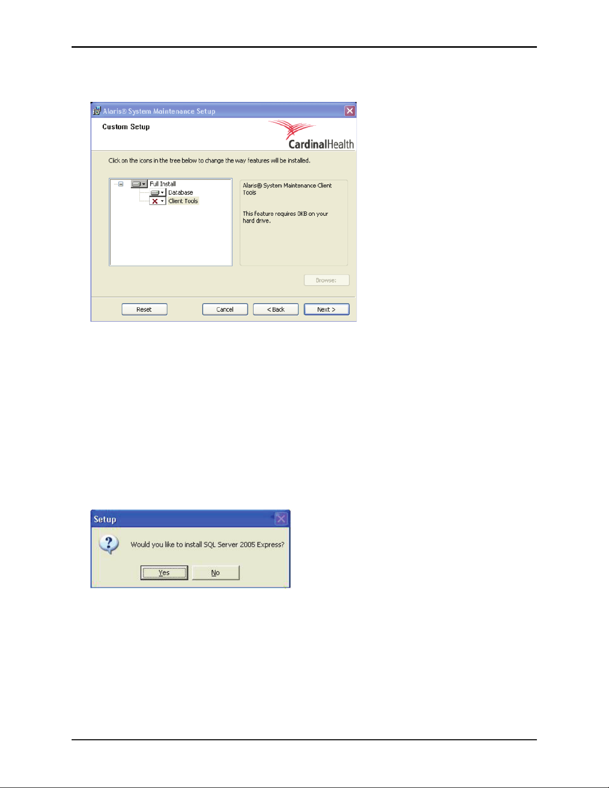
5. Select the features that you want to install:
• Full Install—installs System Maintenance databases and client tools.
• Database—installs only System Maintenance databases.
• Client Tools—installs only System Maintenance client tools.
To install only the database, click
Database and click the red X.
Client Tools and click the red X. To install only the client tools, click
10 Alaris® System Maintenance v9.5.X Software User Manual
Page 17
Install Software—Standard Installation Chapter 2—Installation and Setup
6. Click Browse to choose a location other than the default installation directory. The default directory is
C:\Program Files\Cardinal Health\Alaris Products\Alaris System Maintenance\ .
If an existing database is found, the following window is displayed. You can use the existing database
(default) or overwrite the existing database (previous data will be lost). If a previous System
Maintenance database was not found, this window will not be displayed.
7. Click
8. Click
Next to begin installation of the components of the System Maintenance Software.
Next to confirm installation.
When the installation is finished, an "Installation Complete" message is displayed. It is recommended
that you restart your computer if prompted to do so.
Alaris® System Maintenance v9.5.X Software User Manual 11
Page 18
Chapter 2—Installation and Setup Install Software—Custom Installation
Install Software—Custom Installation
Install Centralized System Maintenance Software Database on a Dedicated Server
1. Insert the System Maintenance Software CD into the CD-ROM drive of the personal computer. If the
installation program starts automatically, go to the next step. If the installation program does not start
automatically , choose
browse to the
OK.
Setup.exe program on the System Maintenance Software CD, click Open, and then click
Start > Run, then type
d:\Setup.exe
(where d: is CD drive). Alternatively,
2. When you are asked if you want to install SQL Server 2005 Express, click
3. If you are prompted to install prerequisite components, click
Install. The components include
Yes.
Microsoft .NET Framework 2.0, MSXML 6.0, Microsoft Report Viewer 2005, ASM Database (SQL
Server Express 2005), and Adobe Reader 9.X.
®
4. Wait until the installation is completed. When the Alaris
displayed, click
12 Alaris® System Maintenance v9.5.X Software User Manual
Next.
System Maintenance welcome wizard is
Page 19
Install Software—Custom Installation Chapter 2—Installation and Setup
5. On the Custom Setup window, ensure that Client Tools is not selected (unless you want to also install
the client tools on the same computer as the System Maintenance database).
6. Click
7. Click
Next.
Finish.
Install Client Tools on Biomedical Technician Workstation
Follow these steps to install the client tools on the Biomedical Technician Workstation.
1. Insert the System Maintenance Software CD into the CD-ROM drive of the personal computer. If the
installation program starts automatically, go to the next step. If the installation program does not start
automatically , choose
browse to the
OK.
Setup.exe program on the System Maintenance Software CD, click Open, and then click
Start > Run, then type
2. When you are asked if you want to install SQL Server 2005 Express, click
d:\Setup.exe
(where d: is CD drive). Alternatively,
No.
Alaris® System Maintenance v9.5.X Software User Manual 13
Page 20
Chapter 2—Installation and Setup Install Software—Custom Installation
3. If you are prompted to install prerequisite components, click Install. The components include
Microsoft .NET Framework 2.0, MSXML 6.0, Microsoft Report Viewer 2005, and Adobe Reader 9.0.
®
4. Wait until the installation is completed. When the Alaris
displayed, click
5. On the Custom Setup window, ensure that
Next.
Database is not selected.
System Maintenance welcome wizard is
6. If the Database option is selected and you chose not to install SQL Server 2005 Express, a message is
displayed. Click
14 Alaris® System Maintenance v9.5.X Software User Manual
Ok to close the message window.
Page 21
Install Software—Custom Installation Chapter 2—Installation and Setup
7. Click Next.
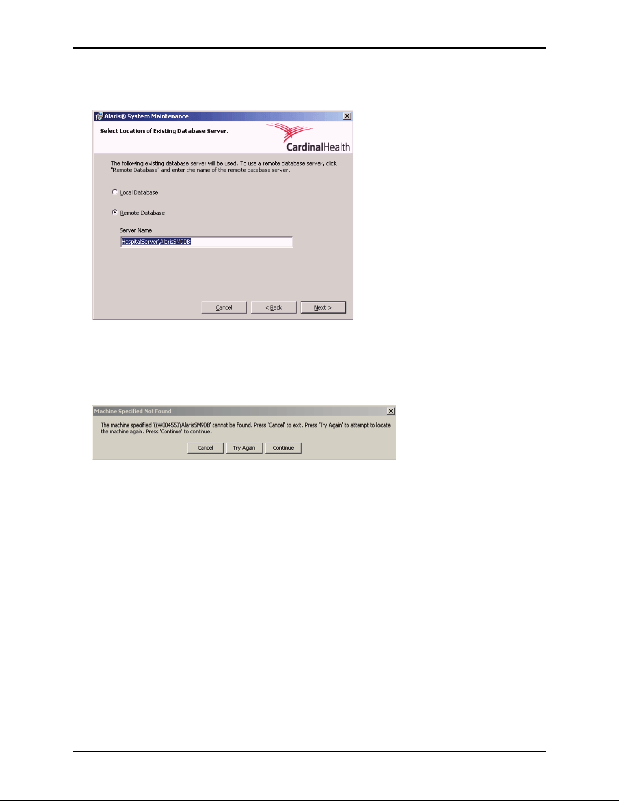
A window that asks you to select the database server is displayed.
8. Choose the
Example:
Remote Database option. Enter the server name and SQL instance.
HospitalServer\AlarisSM9DB
9. Click Next.
A "Machine Specified Not Found" message is displayed.
10. Click
11. Click
12. Click
Continue.
Next to confirm.
Finish.
Configure Database Settings
Follow these steps to configure the database settings.
1. Start the System Maintenance Software.
2. If you are asked to select another database, click
3. If you are not asked, choose
Options > Database Settings on the main menu.
Yes.
The Database Settings dialog box is displayed.
4. Click
Add to configure the connections for the Maintenance database, the Maintenance Log database,
and the CQI Database.
Alaris® System Maintenance v9.5.X Software User Manual 15
Page 22
Chapter 2—Installation and Setup Install Software—Custom Installation
Hospital Server
Database Field Values
Maintenance database SQL Server field =
Database field = Maintenance
Maintenance Log database SQL Server field =
Database field = MaintenanceLog
CQI Database SQL Server field =
Database field = CQI
<HospitalServer>\AlarisSM9DB
<HospitalServer>\AlarisSM9DB
<HospitalServer>\CQI9DB
Standalone Computer
Database Field Values
Maintenance database SQL Server field =
Database field = Maintenance
Maintenance Log database SQL Server field =
Database field = MaintenanceLog
CQI Database SQL Server field =
Database field = CQI
NOTE
(local)\AlarisSM9Db
(local)\AlarisSM9Db
(local)\CQI9DB
If a database does not exist on your local database server, the "(local)" SQL
Service field is replaced with the SQL Server name where the database is
installed.
Alaris
5. Click
®
Server (wireless)
Database Field Values
CQI Database SQL Server field =
Database field = CQI
Test Connection to verify the connection to the database.
<AlarisAPPSServer>
16 Alaris® System Maintenance v9.5.X Software User Manual
Page 23

Upgrade/Reinstall Software Chapter 2—Installation and Setup
Upgrade/Reinstall Software
Before you can upgrade or reinstall the System Maintenance Software, you must uninstall the existing
software.
NOTE
Uninstalling the AlarisSM9DB database is NOT required to upgrade/reinstall the
software (Uninstall AlarisSM9DB Database Instance on page 20).
1. Uninstall the existing software (see Uninstall Software on page 18).
2. Install/reinstall the software (see Install Software—Standard Installation on page 9 or Install
Software—Custom Installation on page 12).
Alaris® System Maintenance v9.5.X Software User Manual 17
Page 24
Chapter 2—Installation and Setup Uninstall Software
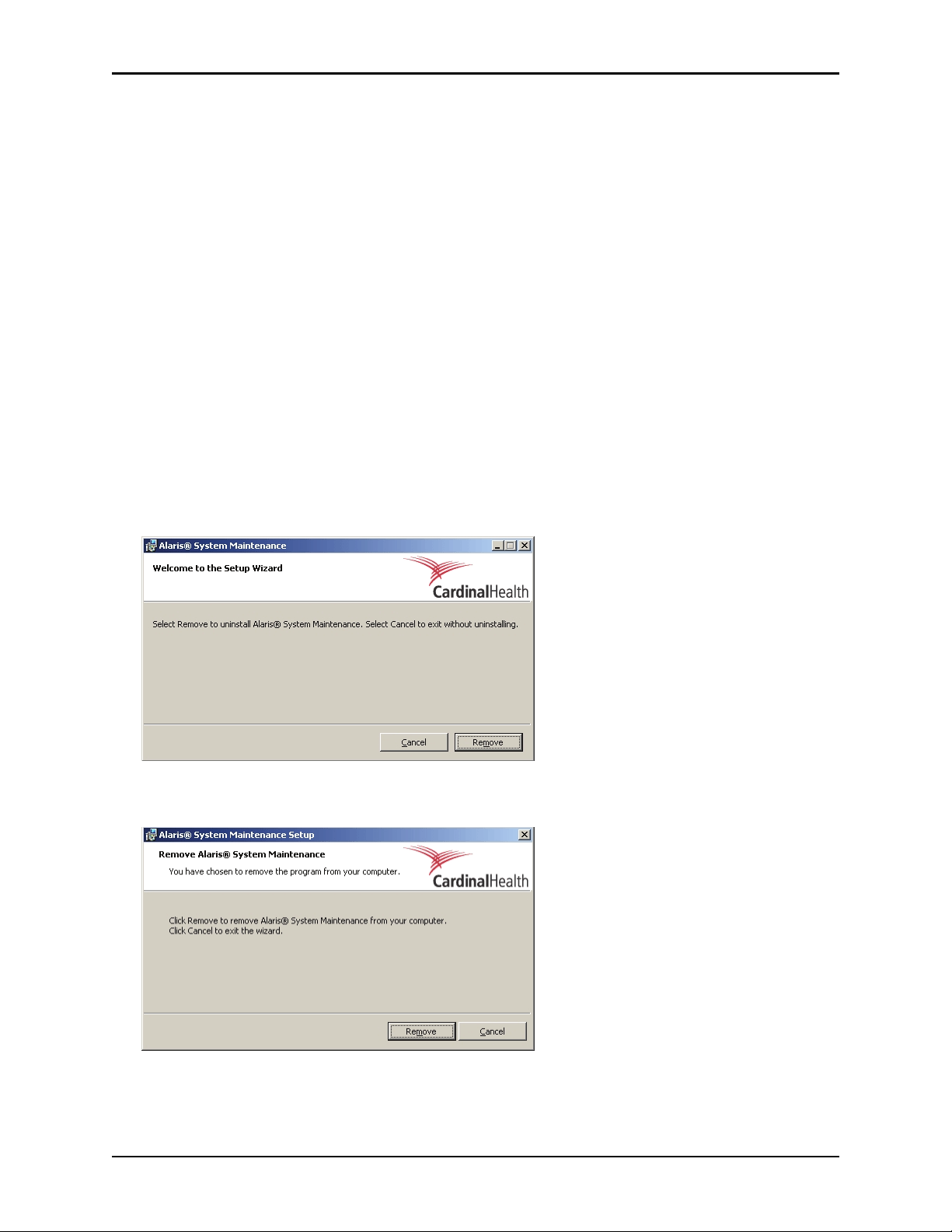
Uninstall Software
There are two ways to uninstall the System Maintenance Software. The method that you use depends on
the version of software that you are uninstalling.
• System Maintenance Software CD: Use this method if the software being removed and the
software that will be installed are the same software version.
• Windows Operating System: Use this method if the software being removed will be replaced with
a different version of the software.
System Maintenance Software CD
1. Insert the System Maintenance Software CD into the CD-ROM drive of the personal computer. The
installation program starts automatically. If the installation program does not start, choose
then type
the System Maintenance Software CD, click
d:\Setup.exe
(where d: is CD drive). Alternatively, browse to the Setup.exe program on
Open, and then click OK.
2. Enter information about installation as prompted, including destination.
Start > Run,
3. When the message that a previous installation has been detected is displayed, click
Remove to
completely remove the existing System Maintenance Software and its components. Existing data is
preserved.
4. Clicking Remove displays the following confirmation window. Click Remove again to initiate the
uninstall process.
5. When a message that indicates the software has been successfully uninstalled is displayed, click
18 Alaris® System Maintenance v9.5.X Software User Manual
Finish.
Page 25

Uninstall Software Chapter 2—Installation and Setup
Windows Operating System
1. Choose Start > Settings > Control Panel.
2. Double-click
3. Click Alaris
Add or Remove Programs.
®
System Maintenance.
4. Click
Remove.
5. Follow the prompts to complete the uninstallation procedure.
Alaris® System Maintenance v9.5.X Software User Manual 19
Page 26
Chapter 2—Installation and Setup Uninstall AlarisSM9DB Database Instance
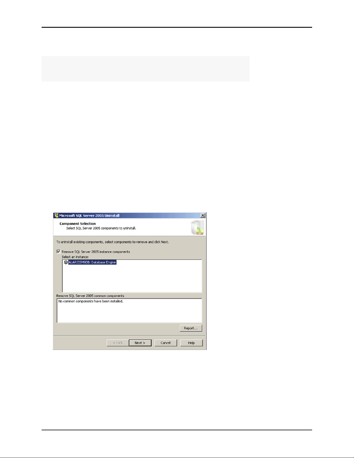
Uninstall AlarisSM9DB Database Instance
NOTE
All data will be lost when uninstalling the AlarisSM9DB database. Ensure that the
database is backed up for future reference.
Use this procedure to uninstall the AlarisSM9DB database instance of Microsoft SQL Server 2005 Express
and the following software:
• Microsoft SQL Server Native Client (if applicable)
• Microsoft SQL Server Setup Support Files (if applicable)
• Microsoft SQL Server VSS Writer (if applicable)
To uninstall the software:
1. Choose
2. Double-click
Start > Settings > Control Panel.
Add or Remove Programs.
3. Select the software (listed above) that you want to uninstall.
4. Click
Remove.
5. Follow the prompts to complete the removal procedure.
If you are uninstalling Microsoft SQL Server 2005, when the following dialog box is displayed, select
the instance named "AlarisSM9DB" and then click
Next to continue with the removal procedure.
20 Alaris® System Maintenance v9.5.X Software User Manual
Page 27

Chapter 3
Overview
Alaris® System Maintenance v9.5.X Software User Manual 21
Page 28
Chapter 3—Overview Start System Maintenance Software
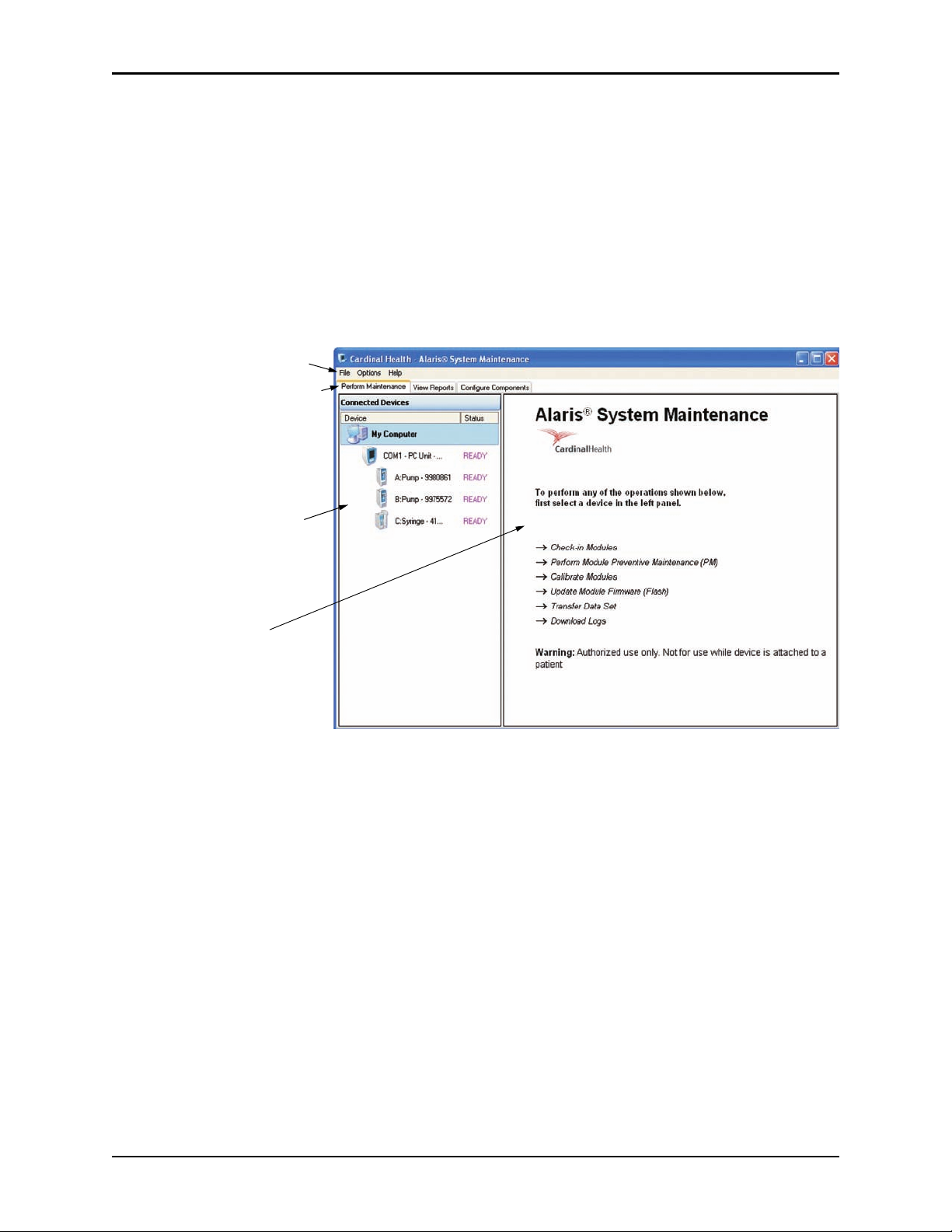
Menu Bar
Tabs in the main window let you
perform maintenance tasks, view
reports from the maintenance
database, configure task lists,
and configure device parameters
The Connected Devices pane
contains a list of the d evices th at
are connected to each of the
communication ports on the
personal computer.
This pane contains task
instructions, input fields, and
report data.
Start System Maintenance Software
1. On the personal computer desktop, double-click the Alaris® System Maintenance icon (or choose the
program from the
A series of status boxes is displayed as the System Maintenance Software scans for communication
ports and establishes communication with connected devices.
When the startup routine is complete, the main window of the System Maintenance Software is
displayed.
Start menu).
2. To check the version of System Maintenance Software, choose
Maintenance.
Help > About Alaris® System
22 Alaris® System Maintenance v9.5.X Software User Manual
Page 29

Menu Bar Chapter 3—Overview
Menu Bar
• File
Refresh (F5)—Refresh all ports.
°
Refresh Selected Port (Ctrl + F5)—Refresh the port that is selected in the Connected Devices pane.
°
Exit (Alt + F4)—Exit the software.
°
•Options
Application Settings—See Application Settings on page 30.
°
Database Settings—See Database Settings on page 31.
°
Export—Export the CQI Database as well as information for all devices that have been connected
°
to the PC Unit.
Import—Import the CQI Database as well as information for all devices that have been connected
°
to the PC Unit.
Migrate MSW Data—Import a previous maintenance software v8 database.
°
•Help
About Alaris
®
System Maintenance—View version and copyright information.
Alaris® System Maintenance v9.5.X Software User Manual 23
Page 30

Chapter 3—Overview Menu Bar
This page intentionally left blank.
24 Alaris® System Maintenance v9.5.X Software User Manual
Page 31

Chapter 4
PC Unit Connection
Alaris® System Maintenance v9.5.X Software User Manual 25
Page 32

Chapter 4—PC Unit Connection Hardware Connections
PC Unit (back)
Communications
port (remove rubber
plug if present)
Serial cable
(both ends shown)
Hardware Connections
This section describes how to connect a PC Unit to the personal computer.
WARNING
At no time should the System Maintenance Software be used while the
®
Alaris
1. If a rubber plug is covering the communications port, remove it.
System is connected to a patient.
2. Connect the small end of the serial cable to the communications port on the back of the PC Unit.
3. Connect the large end of the serial cable to a serial port on the personal computer.
4. If the PC Unit is not on, press the
System On key .
5. If the System Maintenance Software is not running, start it.
6. Press F5 to refresh the ports.
Information about the PC Unit and attached modules is displayed in the Connected Devices pane.
26 Alaris® System Maintenance v9.5.X Software User Manual
Page 33

Multiple PC Unit Connections Chapter 4—PC Unit Connection
Multiple PC Unit Connections
You can connect as many PC Units as there are available serial COM ports on the personal computer. To
view all available COM ports:
1. On the main menu, click
2. In the drop-down menu labeled
Options > Application Settings.
Show only connected ports, click False.
3. Close the Application Settings window.
After a File/Refresh, a list of all available COM ports is displayed in the Connected Devices pane,
whether or not they have a PC Unit attached.
4. Connect the PC Units to the available ports.
5. Press F5 to refresh the view for all ports, or press Ctrl+F5 to refresh only the port that is selected in the
Available Devices pane. These options are also available in the
File menu.
When a port refresh is selected, a list of connected devices is displayed in the Connected Devices pane.
If problems occur when using the refresh feature while connected to a 4-port replicator, consider
restarting the System Maintenance Software to restore the connection.
Alaris® System Maintenance v9.5.X Software User Manual 27
Page 34

Chapter 4—PC Unit Connection Multiple PC Unit Connections
This page intentionally left blank.
28 Alaris® System Maintenance v9.5.X Software User Manual
Page 35

Chapter 5
Application and Database Settings
Alaris® System Maintenance v9.5.X Software User Manual 29
Page 36

Chapter 5—Application and Database Settings Application Settings
Application Settings
Use the Application Settings dialog box to configure the available application options for the System
Maintenance Software. To open the Application Settings dialog box:
1. On the main menu, choose
Options > Application Settings.
The Application Settings dialog box is displayed.
2. To change an application setting, click the column to the right of that setting and make the appropriate
change.
3. Close the Application Settings dialog box to save your changes.
Setting Description
Flash
• Allow serial number update If true, the device serial number can be set through flash
tasks.
• Default SpO
General
• Beep for user input If true, causes application to beep when a running task
• Beep on finished task If true, causes application to beep when a task finishes.
• Enable task list edit button If true, task list edit button is enabled, allowing Task
Module for Flash When flashing the firmware on an SpO2 Module, either
2
®
Nellcor
firmware.
requires attention.
List to be edited.
or Masimo® can be selected as the default
• Show only connected ports If true, only communication ports that have devices
Log Downloading
• Clear downloaded CQI logs If true, CQI logs are cleared from connected devices
• Clear downloaded logs If true, all battery, error, and event logs (other than CQI
Package Components
Ignore incomplete packages If true, any empty packages are ignored and do not
connected to them are displayed in the Connected
Devices pane. If false, all available ports are displayed.
If either clear downloaded logs setting is set to
the software automatically clears the log during
download. If you are performing an instrument
investigation, CareFusion recommends that the logs not
be cleared until the investigation is completed.
after download.
logs) are cleared from connected devices after
download. This setting does not affect whether CQI logs
are cleared after downloading. The clearing of CQI logs
after downloading is managed separately from all other
settings used to clear logs.
produce an error.
True
,
30 Alaris® System Maintenance v9.5.X Software User Manual
Page 37

Database Settings Chapter 5—Application and Database Settings
Select a tab to display the list
of database definitions for the
selected System Maintenance
Softw are database.
Database definitions relating
to the selected tab display
here. The active definition has
Default set to Yes.
Database Settings
Multiple database definitions can be defined for the three System Maintenance Software databases
(Maintenance database, Maintenance Log database, and CQI database). Each definition contains the server
name and authentication for the databases. Once defined, the user can select which database to use from
this list of defined databases.
Once defined, do not change database settings unless you have a valid reason for doing so. For example,
you may need to select a site-specific database in an environment that supports multiple hospital sites.
The System Maintenance Software automatically connects to the default database locations, but additional
customizing may need to occur if your database definition is different from these default parameters.
Open Database Settings
On the main menu, choose Options > Database Settings.
The Database Selection dialog box is displayed.
Alaris® System Maintenance v9.5.X Software User Manual 31
Page 38

Chapter 5—Application and Database Settings Database Settings
Add a Database Definition
1. Click the tab of the desired System Maintenance Software database.
2. Click
3. Select an SQL Server.
4. Select a Database name on this SQL Server.
5. Click
6. Click
Add.
The Database Settings dialog box is displayed.
Test Connection to test the connection to the server.
OK to acknowledge the test connection.
7. Click
OK to save the definition.
Delete a Database Definition
1. Click the tab of the desired System Maintenance Software database.
2. Click the database definition that you want to delete.
3. Click
Delete.
A confirmation dialog box is displayed.
4. Click
OK to delete the database definition.
Set Active Database Definition
1. Click the tab of the desired System Maintenance Software database.
2. Click the database definition to make it active.
3. Click
Set Default.
The System Maintenance Software now uses the selected definition as the active database and begins
logging data to it as data is collected.
Test Database Definition Connection
1. Click the tab of the desired System Maintenance Software database.
2. Click the database definition to select it.
3. Click
Test Connection.
If the connection fails, check the database definition for errors.
32 Alaris® System Maintenance v9.5.X Software User Manual
Page 39

Migrate MSW Databases Chapter 5—Application and Database Settings
Migrate MSW Databases
There are two separate MSW application databases, MSW and MSW Log. Use the following procedure to
migrate the MSW databases to the System Maintenance Software database.
1. On the main menu, click
The Database Selection screen is displayed:
Options > Migrate MSW Data.
2. If the desired MSW or MSW Log databases are not listed, continue with the following steps;
otherwise, proceed to step 3.
NOTE
The desired MSW databases (MSW and MSW Log) must be configured as
default DB.
Alaris® System Maintenance v9.5.X Software User Manual 33
Page 40

Chapter 5—Application and Database Settings Migrate MSW Databases
a. Click the tab for the applicable database and then click Add. The Database Settings screen is
displayed.
b. Select the desired server from the SQL Server drop-down list.
c. From the Database name drop-down list, select MTR for the MSW database or IMSLog for the
MSW Log database.
NOTE
If the required database is not in the Database name drop-down list, the selected
SQL Server is not correct.
d. Click
Test Connection to have the software verify that the MSW database configuration is correct.
3. Click on desired database.
4. Click
Migrate—located at the bottom of the Database Selection screen—to start data migration.
The data migration progress screen is displayed. When the migration process is complete, the
application displays the status of the migration.
34 Alaris® System Maintenance v9.5.X Software User Manual
Page 41

Chapter 6
Preventive Maintenance
Alaris® System Maintenance v9.5.X Software User Manual 35
Page 42

Chapter 6—Preventive Maintenance Introduction—
Introduction
WARNING
At no time should the System Maintenance Software be used while the
®
Alaris
Preventive maintenance can be performed on connected modules by selecting from a list of automated
tasks. Tasks can be individual tasks that exist in the list of master tasks or task groups that contain a
collection of the individual tasks required to maintain devices.
Standard task groups include:
System is connected to a patient.
Check-in
Preventive Maintenance
Calibration
T asks required to check any module newly received into
the facility . Run check-in on a newly received module to
confirm that it was not damaged during transport and is
ready to be put into use. System Maintenance Software
guides you through check-in.
The final task in the Check-in task group allows you to
set a Preventive Maintenance (PM) Reminder Date to
remind the user when preventive maintenance is due.
Tasks required to perform regular maintenance on a
module.
Run preventive maintenance tests a minimum of once a
year to confirm that modules are performing correctly.
System Maintenance Software guides you through
preventive maintenance tests.
Final task in Preventive Maintenance task group allows
you to set the next PM Reminder Date to remind the
user when preventive maintenance is due.
T asks required to test whether calibration is required and
to calibrate connected modules.
The calibration task group applies to EtCO
Syringe Module, PCA Module, and Pump Module.
Module,
2
36 Alaris® System Maintenance v9.5.X Software User Manual
Page 43

Introduction—General Steps Chapter 6—Preventive Maintenance
General Steps
The main window is shown below. When you click a node such as My Computer in the Connected Devices
pane, information on how to proceed is displayed in the right pane.
1. Click the
Perform Maintenance tab.
2. Select the module (device).
The Tasks list is displayed.
NOTE
• The tasks in the Tasks list vary depending on which module you have
selected and how the tasks are configured.
• You can edit the Tasks list, if desired (see Tasks List on page 168).
Alaris® System Maintenance v9.5.X Software User Manual 37
Page 44

Chapter 6—Preventive Maintenance Introduction—General Steps
3. Click Preventive Maintenance in the Tasks list (Pump Module screen used as an example in following
illustration).
NOTE
As a shortcut, you can double-click the task to select it and start it immediately.
4. If Preventive Maintenance was not automatically started, click
Start Selected Tasks.
5. Follow all on-screen instructions carefully to ensure the successful completion of the task.
If a task fails, the System Maintenance Software asks you if you want to rerun the failed task.
NOTE
At the end of some tests you are asked to indicate if the test passed or failed.
Other tests automatically indicate a pass or fail result.
To rerun the task, click Yes.
°
To continue to the next task in a task group, click No.
°
To correc t a failure, abort the selected task and refer to the applicable Technical Service Manual.
°
38 Alaris® System Maintenance v9.5.X Software User Manual
Page 45

Introduction—Run/Abort Tasks Chapter 6—Preventive Maintenance
6. When finished, click Reset Selected Tasks to return a module to the READY state (Pump Module screen
used as an example in following illustration).
Run/Abort Tasks
Run Tasks Concurrently
You can run selected tasks concurrently on different connected modules. One PC Unit and a serial port is
needed for each module being tested. Once you have started selected tasks on one connected device, select
other devices in the Connected Devices pane and start tasks for those devices, if desired.
The status bar displays devices that are currently running tasks. If attention is required by a device to
continue a task, the device progress bar and the Details Pane Task button for that task will be orange.
Select the device in the Connected Devices pane to display its task instructions and follow the displayed
task instructions.
The System Maintenance Software sounds an alarm when a device needs attention or when a task is
finished, if these options are set. For information on setting these options, see Application Settings on
page 30.
Alaris® System Maintenance v9.5.X Software User Manual 39
Page 46

Chapter 6—Preventive Maintenance Introduction—Coloring Scheme
Abort Tasks
You can abort (cancel) any running task that is currently selected in the Connected Devices pane.
Abort Selected Tasks.
Click
The status of the task is reset to
CANCEL.
Coloring Scheme
The preventive maintenance test results are identified using the following color scheme:
Blue—test passed
Brown—test aborted
Red—test failed
Orange—test is running, but waiting for user input
Purple—test has not yet been run
Green—test is automatically running (not requiring user input at this time)
Example:
40 Alaris® System Maintenance v9.5.X Software User Manual
Page 47

Preventive Maintenance—PC Unit Chapter 6—Preventive Maintenance
Preventive Maintenance
To perform preventive maintenance, see the procedure in this section that applies to the module being
tested:
PC Unit on page 41
Pump Module on page 47
PCA Module on page 59
Syringe Module on page 67
Module on page 77
SpO
2
EtCO
Module on page 84
2
Auto-ID Module and Handheld Scanner on page 91
PC Unit
Test Equipment
Test Equipment Manufacturer Model Number Application
analyzer, electrical safety Fluke BioMedical 232D or equivalent ground tests
1. In the Connected Devices pane, click the PC Unit to be tested.
2. Click
Preventive Maintenance in the Tasks list (double-click to begin testing immediately).
3. Follow the instructions displayed on the screen for each test.
NOTE
See PC Unit Tasks on page 170 for an explanation of each task.
Alaris® System Maintenance v9.5.X Software User Manual 41
Page 48

Chapter 6—Preventive Maintenance Preventive Maintenance—PC Unit
If the test failed, click Abort Selected Tasks—in
the T asks list—to discontinue testing. Correct the
failure(s) before continuing with the tests.
4. Instrument Inspection:
42 Alaris® System Maintenance v9.5.X Software User Manual
Page 49

Preventive Maintenance—PC Unit Chapter 6—Preventive Maintenance
'Sandwiching'—the PC Unit has one module
attached to each side.
5. Simultaneous Display:
If you want the test to run continuously, click the
Run test in continuous mode checkbox.
• Look for missing pixels (display elements) as each screen is displayed.
• The Model 8000 displays dark gray and light gray screens. The Model 8015 displays dark gray,
light gray, white, red, green, and blue screens.
• If the screen brightness or contrast appears weak, check the contrast setting (refer to applicable
®
Alaris
System DFU).
6. IUI Connectors:
Alaris® System Maintenance v9.5.X Software User Manual 43
Page 50

Chapter 6—Preventive Maintenance Preventive Maintenance—PC Unit
If the audio is weak, check the audio volume
setting (refer to applicable Alaris
®
System DFU).
7. Alarm:
8. Keypad:
NOTE
Press and hold the Tamper Switch (on back of PC Unit) for at least two seconds,
until there is a response to the test.
Press each key one time.
• Green text—the key was pressed one time and passed the test.
• Red text—the key was pressed two times, or it was pressed one time and failed the test. If the text
is red because you pressed the key more than one time, you can indicate that the test has passed.
9. Nurse Call:
This test is performed only if a Nurse Call is installed and applies only to the Model 8000.
44 Alaris® System Maintenance v9.5.X Software User Manual
Page 51

Preventive Maintenance—PC Unit Chapter 6—Preventive Maintenance
Use a Fluke Biomedical Model 232D or
equivalent electrical safety analyzer to measure
the ground leakage current. Refer to the test
equipment’s operation manual for the proper
measurement technique.
The line voltage must be the same as the voltage
that powers the tester and then passes to the
instrument being tested.
Use the following table—in place of the
requirements identified by the software—to
determine the leakage current requirements for
normal and reversed line polarity. The limits are
100 µA below the IEC/UL 60601-1 standard
limits to account for test variances.
AC Supply
Leakage Current—
Maximum
Japan 100 VAC 400
µA
North America 120 VAC 200
µA
Rest of World 230 VAC 400
µA
Australia
New Zealand
240 VAC 400
µA
Use a Fluke Biomedical Model 232D , an Ohm
Meter, or an equivalent electrical safety analyzer
to measure the ground resistance between the
ground pin on power cord plug or power cord
receptacle, and the rear panel of the PC Unit. Refer
to the test equipment’s operation manual for the
proper measurement technique.
The maximum allowable resistance is 1 Ohm.
10. Ground Leakage:
The ground leakage test is not performed by the System Maintenance Software. The leakage current
table provided below reflects IEC/UL 60601-1 requirements. The limits identified in the table are to be
used in place of the 100 µA leakage current limit specified by the software.
11. Ground Resistance:
The ground resistance test is not performed by the System Maintenance Software. Use the following
instructions and illustration to perform this test—in place of the instructions displayed by the software.
Alaris® System Maintenance v9.5.X Software User Manual 45
Page 52

Chapter 6—Preventive Maintenance Preventive Maintenance—PC Unit
The following illustration is a partial view of the rear of the PC Unit. In the illustrated example of
a ground contact, a Kelvin Clip is clipped to a speaker slot on the rear panel. The only acceptable
ground contact area is the rear panel—gold anodized color metal (shaded area in illustration).
NOTE
The following illustration reflects the use of the Kelvin Clip that is provided with
the Fluke tester. If another tester or Ohm Meter is used, the test measures the
resistance between the rear panel (shaded area in illustration) and the ground pin
on the power cord plug or power cord receptacle.
12. Set PM Reminder:
• If
Enable Maintenance Reminder is selected, a Data Set is loaded and the configuration option for
the Data Set is set to Disable. The Data Set setting overrides the System Maintenance Software
selection.
• The next maintenance reminder date defaults to 12 months. The reminder can be set to an earlier
date but it cannot be set to a date past the 12-month default.
46 Alaris® System Maintenance v9.5.X Software User Manual
Page 53

Preventive Maintenance—Pump Module Chapter 6—Preventive Maintenance
Pump Module
Test Equipment
Test Equipment Manufacturer Model/Part Number Application
gauge
, pressure, digital
(peak hold)
hemostat N/A N/A fluid-side occlusion test
IV pole, standard CareFusion 903-0336 or equivalent rate, pressure, and occlusion tests
Either of the following:
• Heise
(www.heise.com)
• Ashcroft
(www.ashcroft.com)
• PTE-1 (accuracy from 0.1 to
0.025% span)
• 2089, 2086, or 2084 (accuracy
from ±0.05%, 0.10%, or
0.25% of span)
• or an equivalent gauge with:
(a) unit of measure in mmHg
(b) accuracy of ±1%
(c) range of 0-1500 mmHg
pressure test
IV sets
• IV set, standard,
without check valve
• IV set, calibration
• IV set, calibration
IV solution container
(bag preferred)
luer lock, female,
1/8"-27 NPT
reducer, female,
1/4" NPT (F) x
1/8" NPT (F)
scale, digital Acculab
tubing, silicone CareFusion 303109 or equivalent pressure test
T-fitting CareFusion 303815 or equivalent pressure test
valve, 3-way CareFusion 97555 or equivalent pressure test
• CareFusion
• CareFusion
• CareFusion
N/A N/A rate and pressure tests
Cole-Parmer
(www.coleparmer.com)
Cole-Parmer
(www.coleparmer.com)
(www.acculab.com)
• 2210-0500
• 8100-RCS
• 8100-PCS
K-45503-78 or equivalent pressure test
K-06349-91 or equivalent pressure test
VIC-212 (VICON Series) or
equivalent with accuracy of
±0.01g
rate and pressure tests
rate and pressure tests
Alaris® System Maintenance v9.5.X Software User Manual 47
Page 54

Chapter 6—Preventive Maintenance Preventive Maintenance—Pump Module
1. In the Connected Devices pane, click the Pump Module to be tested.
2. Click
Preventive Maintenance in the Tasks list (double-click to begin testing immediately).
3. Follow the instructions displayed on the screen for each test.
NOTE
See Pump Module Tasks on page 175 for an explanation of each task.
4. Instrument Inspection:
48 Alaris® System Maintenance v9.5.X Software User Manual
Page 55

Preventive Maintenance—Pump Module Chapter 6—Preventive Maintenance
If the test failed, click Abort Selected Tasks to discontinue testing. Correct the failure(s) before
continuing with the tests.
5. Simultaneous Display:
If you want the test to run continuously, select
Run test in continuous mode.
• Channel ID display—all segments must light.
• Scrolling display and Rate display—must flash dashes and zeros.
• Lighthouse LED’s—all LEDs must light.
Alaris® System Maintenance v9.5.X Software User Manual 49
Page 56

Chapter 6—Preventive Maintenance Preventive Maintenance—Pump Module
’Sandwiching’—the module being tested is connected
between the PC Unit and another module.
If the audio is weak, check the audio volume
setting (refer to applicable Alaris
®
System DFU).
6. IUI Connectors:
7. Alarms:
If the audio is weak, check the audio volume setting (refer to applicable Alaris
®
System DFU).
8. Keypad:
Press each key one time.
• Green text—the key was pressed one time and passed the test.
• Red text—the key was pressed two times, or it was pressed one time and failed the test. If the text
is red because you pressed the key more than one time, you can indicate that the test has passed.
50 Alaris® System Maintenance v9.5.X Software User Manual
Page 57

Preventive Maintenance—Pump Module Chapter 6—Preventive Maintenance
Ensure that the pumping
segment is vertical across the
center of the pressure sensors.
Ensure that the tubing is fully
inserted in the Air-in-Line
Sensor.
9. Door Ajar-Flo-Stop Sensors:
54
Load Administration Set
Install an administration set as shown for any Pump Module test. Unless otherwise specified, in order
to run a Pump Module test, the set must be loaded and the Pump Module door must be closed.
Alaris® System Maintenance v9.5.X Software User Manual 51
Page 58

Chapter 6—Preventive Maintenance Preventive Maintenance—Pump Module
10. Air-in-Line Sensor:
11. Rate Accuracy
CAUTION
If the Pump Module fails the rate accuracy test, calibration is required. Failure to
perform calibration tests might result in improper operation.
:
Set up the Pump Module for the Rate Accuracy test.
Rate Accuracy Test Setup
CAUTION
• If the Pump Module fails the rate accuracy verification test, calibration is
required. Failure to perform calibration tests might result in impro per
operation.
• To ensure accurate rate calibration, use only rate calibration sets. Rate
accuracy calibration sets are valid for 60 calibrations and must be replaced
after 60 uses.
• Use distilled water at room temperature of 41°F to 104°F (5°C to 40°C). If the
water temperature is not within this range, the readings might be inaccurate.
Use this setup to perform the following tests:
• Rate accuracy verification—Tasks: Rate Accuracy, Check-in, and Preventive Maintenance.
• Rate accuracy calibration pre-test—Task: Rate Accuracy Pre-Test.
• Rate accuracy calibration—Task: Rate Calibration.
• Rate accuracy calibration post-test—Task: Rate Accuracy Post-Test.
All tests use a standard set except for the rate accuracy verification (Task: Preventive Maintenance)
and the rate accuracy calibration. These tests require the use of the Model 8100-RCS rate calibration
set.
Verify that the scale is calibrated according to the manufacturer's instructions. Prime the fluid lines and
keep them free of air bubbles while running the test.
If the rate accuracy calibration pre-test fails, perform the rate accuracy calibration. Following
calibration, run the rate accuracy calibration post-test using a different rate calibration set to test the
module with the newly calibrated parameters.
—See the test setup illustration on the following page.—
52 Alaris® System Maintenance v9.5.X Software User Manual
Page 59

Preventive Maintenance—Pump Module Chapter 6—Preventive Maintenance
20±1 inch
1
4
7
CLEAR
2
5
8
0
3
6
9
.
ENTER
CANCEL
SYSTEM
PUMP
PUMP
RESTART
CHANNEL
OFF
CHANNEL
SELECT
PAUSE
RESTART
CHANNEL
OFF
CHANNEL
SELECT
PAUSE
Top of cup must be
level with CHANNEL
SELECT key .
Distance is from top
of Pump Module
Ensure that the set is properly loaded (see Load
Administration Set on page 51). Ensure that
there are no air bubbles in the set when priming
is completed.
The
Expected Volume is identified on the label
attached to the characterized set.
Error message—first occurrence
If an error message appears after clicking
Next, perform the following steps.
NOTE
If this is not the first occurrence of an error message and the following procedure
has already been performed, perform Error message—repeat occurrence.
Alaris® System Maintenance v9.5.X Software User Manual 53
Page 60

Chapter 6—Preventive Maintenance Preventive Maintenance—Pump Module
Ensure that the distilled water is dripping into the
cup and that the tubing is not resting on the scale.
a. Click OK and visually confirm that:
• The set is properly loaded in the Pump Module.
• There are no air bubbles in the set.
b. Click
Yes on the message that appears.
c. Detach and reattach the Pump Module with set installed.
d. Repeat the rate accuracy test after the Pump Module reinitializes.
Error message—repeat occurrence
If an error message appears after clicking
Next, manually connect to the Maintenance Mode and
retest, as follows:
a. Abort the selected task.
a. Exit the System Maintenance Software.
b. Turn off the PC Unit.
c. Ensure that the serial cable is connected between the communications port on the PC Unit and
the computer.
d. Press and hold the Tamper Switch and the System On key on the PC Unit until the PC Unit
beeps once and displays the Maintenance Mode screen.
e. Press the Proceed soft key and then press the External Communications soft key.
f. Start the System Maintenance Software.
g. Perform Preventive Maintenance.
When performing the Rate Accuracy test, follow the instructions to ensure that the set is
properly loaded and that there are no air bubbles in the set when priming is completed.
54 Alaris® System Maintenance v9.5.X Software User Manual
Page 61

Preventive Maintenance—Pump Module Chapter 6—Preventive Maintenance
12. Patient-Side Occlusion:
Set up the Pump Module for the Patient-Side Occlusion test.
Patient-Side Occlusion Pressure Test Setup
CAUTION
If a Pump Module fails the patient-side occlusion pressure test, calibration is
required. Failure to calibrate and retest the instrument might result in improper
instrument operation.
Use this setup to perform the following tests:
• Patient-side occlusion pressure test—Tasks: Patient-Side Occlusion, Ch e ck -in, an d Preventive
Maintenance.
• Occlusion pressure calibration pre-test—Task: Pressure Pre-Test. If this test fails, perform
calibration—Task: Pressure Calibration. After calibration, run the calibration post-test—Task:
Pressure Post-Test—with the newly calibrate d parameters using the same standard set that was
used to perform the pre-test.
• Occlusion pressure calibration post-test—Task: Pressure Post-Test.
All tests use a standard set.
—See the test setup illustration on the following page.—
Alaris® System Maintenance v9.5.X Software User Manual 55
Page 62

Chapter 6—Preventive Maintenance Preventive Maintenance—Pump Module
0000
SILENCE
OPTIONS
1
4
7
CLEAR
2
5
8
0
3
6
9
.
ENTER
CANCEL
SYSTEM
ON
PUMP
Closeclamp before
openingdoor
PUMP
Closeclamp before
openingdoor
RESTART
CHANNEL
OFF
CHANNEL
SELECT
PAUSE
RESTART
CHANNEL
OFF
CHANNEL
SELECT
PAUSE
20± 1 inch
Distance from top
of Pump Module
Digital Liquid
Pressure Gauge
Gauge level with
RESTART key
Minimize tubing length
to pressure gauge
Standard Set
3-Way Valve
Fluid Collection Container
After 0.4 ml has been delivered, simulate a
patient-side occlusion by flipping the stop cock
on the 3-way valve so that fluid is pumping
toward the pressure transducer.
56 Alaris® System Maintenance v9.5.X Software User Manual
Page 63

Preventive Maintenance—Pump Module Chapter 6—Preventive Maintenance
SILENCE
OPTIONS
1
4
7
CLEAR
2
5
8
0
3
6
9
.
ENTER
CANCEL
SYSTEM
ON
PUMP
PUMP
RESTART
CHANNEL
OFF
CHANNEL
SELECT
PAUSE
RESTART
CHANNEL
OFF
CHANNEL
SELECT
PAUSE
16" distance from top
of Pump Module
Clamp (Hemostat)
Standard Set
Fluid Collection Container
13. Fluid-Side Occlusion:
Set up the Pump Module for the Fluid-Side Occlusion test.
Fluid-Side Occlusion Test Setup
CAUTION
If the Pump Module fails the fluid-side occlusion test, the module is in need of
repair.
Alaris® System Maintenance v9.5.X Software User Manual 57
Page 64

Chapter 6—Preventive Maintenance Preventive Maintenance—Pump Module
To simulate a fluid-side occlusion after 0.4 mL
has been delivered, clamp the tubing 16 inches
above Pump Module.
14. Set PM Reminder:
The next maintenance reminder date defaults to 12 months. The reminder can be set to an earlier date
but it cannot be set to a date past the 12-month default.
58 Alaris® System Maintenance v9.5.X Software User Manual
Page 65

Preventive Maintenance—PCA Module Chapter 6—Preventive Maintenance
PCA Module
Test Equipment
Test Equipment Manufacturer Model/Part Number Application
door key CareFusion 10010964 lock and unlock PCA Module
door.
Dose Request Cord CareFusion 10013795 display test
gauge, syringe height CareFusion 148181-100 plunger position calibration /
verification
kit, calibration tools
a
CareFusion 10010692 all tools required for
calibration and verification
kit, force sensor CareFusion 10010691 force sensor calibration /
verification
kit, syringe sizer and height
gauge
CareFusion 148182-100 plunger position / barrel size
calibration / verification
kit, syringe sizer gauge CareFusion 148180-100 barrel size calibration /
verification
a. To check the spring cartridge verification, preload the cartridge with 0.50 ±0.05 lbs. Measure the deflection from the preload
point after adding 19.5 lbs additional load (20 ±0.05 lbs total). Acceptable deflection is within 0.891-0.940 inches. Use of
Instron or equivalent is recommended.
1. In the Connected Devices pane, click the PCA Module to be tested.
2. Click
Preventive Maintenance in the Tasks list (double-click to begin testing immediately).
Alaris® System Maintenance v9.5.X Software User Manual 59
Page 66

Chapter 6—Preventive Maintenance Preventive Maintenance—PCA Module
3. Follow the instructions displayed on the screen for each test.
NOTE
See Syringe Module and PCA Module Tasks on page 178 for an explanation of
each task.
4. Instrument Inspection:
If the test failed, click
Abort Selected Tasks to discontinue testing. Correct the failure(s) before
continuing with the tests.
60 Alaris® System Maintenance v9.5.X Software User Manual
Page 67

Preventive Maintenance—PCA Module Chapter 6—Preventive Maintenance
'Sandwiching'—the module being tested is connected
between the PC Unit and another module. The other
module cannot be a PCA Module.
5. Simultaneous Display:
If you want the test to run continuously, click the
Run test in continuous mode checkbox.
• Channel ID display—all segments must light.
• Scrolling display and Rate display—must flash dashes and zeros.
• Lighthouse LED’s—all LEDs must light.
• Dose request cord LED—plug dose request cord into Auto-ID Module for this test.
6. IUI Connectors:
\
Alaris® System Maintenance v9.5.X Software User Manual 61
Page 68

Chapter 6—Preventive Maintenance Preventive Maintenance—PCA Module
7. Alarm:
®
If the audio is weak, check the audio volume setting (refer to applicable Alaris
System DFU).
8. Keypad:
Press each key one time.
• Green text—the key was pressed one time and passed the test.
• Red text—the key was pressed two times, or it was pressed one time and failed the test. If the text
is red because you pressed the key more than one time, you can indicate that the test has passed.
9. Binary Switches:
62 Alaris® System Maintenance v9.5.X Software User Manual
Page 69

Preventive Maintenance—PCA Module Chapter 6—Preventive Maintenance
The door key is needed to lock the door.
To access the plunger detect switch, open the knob
and push the plunger detect switch up.
Alaris® System Maintenance v9.5.X Software User Manual 63
Page 70

Chapter 6—Preventive Maintenance Preventive Maintenance—PCA Module
Insert the 15 mm diameter fixture behind the barrel
clamp and close the barrel clamp on the fixture.
Remove the 15 mm diameter fixture, insert the
25 mm diameter fixture, and close the barrel clamp
on the fixture. A popup alerts you if the correct size
fixture is not installed.
IMPORTANT: To avoid damage to the plunger
header, ensure that the plunger header is not
attached to the calibration fixture.
10. Barrel Clamp Accuracy:
11. Plunger Force Accuracy:
64 Alaris® System Maintenance v9.5.X Software User Manual
Page 71

Preventive Maintenance—PCA Module Chapter 6—Preventive Maintenance
IMPORTANT: To avoid instrument damage, do not
move the plunger head during this test.
Follow the instructions on the screen and then close
the barrel clamp on the 27 mm fixture before
pressing
Next.
Remove the 27 mm diameter fixture, insert the
127 mm diameter fixture, close the barrel clamp on
the fixture. A popup alerts you if the correct size
fixture is not installed.
12. Plunger Position Accuracy:
Alaris® System Maintenance v9.5.X Software User Manual 65
Page 72

Chapter 6—Preventive Maintenance Preventive Maintenance—PCA Module
13. Set PM Reminder Date:
The next maintenance reminder date defaults to 12 months. The reminder can be set to an earlier date
but it cannot be set to a date past the 12-month default.
66 Alaris® System Maintenance v9.5.X Software User Manual
Page 73

Preventive Maintenance—Syringe Module Chapter 6—Preventive Maintenance
Syringe Module
Test Equipment
Test Equipment Manufacturer Model/Part Number Application
extension set, with pressure
disc, small bore
gauge
, pressure, digital
(peak hold)
gauge, syringe height CareFusion 148181-100 plunger position calibration /
kit, calibration tools
kit, force sensor CareFusion 10010691 force sensor calibration /
kit, syringe sizer and height
gauge
kit, syringe sizer gauge CareFusion 148180-100 barrel size calibration /
a
CareFusion 10014917 pressure test
Either of the following:
• Heise (www.heise.com)
• Ashcroft
(www.ashcroft.com)
CareFusion 10010692 all tools required for
CareFusion 148182-100 plunger position / barrel size
• PTE-1 (accuracy from 0.1
to 0.025% span)
• 2089, 2086, or 2084
(accuracy from ±0.05%,
0.10%, or 0.25% of span)
• or an equivalent gauge
with:
(a) unit of measure in
mmHg
(b) accuracy of ±1%
(c) range of 0-1500 mmHg
pressure test / calibration
verification
calibration and verification
verification
calibration / verification
verification
tubing, silicone CareFusion 303109 or equivalent pressure test
valve, 3-way CareFusion 97555 or equivalent pressure test
a. To check the spring cartridge verification, preload the cartridge with 0.50 ±0.05 lbs. Measure the deflection from
the preload point after adding 19.5 lbs additional load (20 ±0.05 lbs total). Acceptable deflection is within 0.891-
0.940 inches. Use of Instron or equivalent is recommended.
Alaris® System Maintenance v9.5.X Software User Manual 67
Page 74

Chapter 6—Preventive Maintenance Preventive Maintenance—Syringe Module
1. In the Connected Devices pane, click the Syringe Module to be tested.
2. Click
Preventive Maintenance in the Tasks list (double-click to begin testing immediately).
3. Follow the instructions displayed on the screen for each test.
NOTE
See Syringe Module and PCA Module Tasks on page 178 for an explanation of
each task.
4. Instrument Inspection:
68 Alaris® System Maintenance v9.5.X Software User Manual
Page 75

Preventive Maintenance—Syringe Module Chapter 6—Preventive Maintenance
If the test failed, click Abort Selected Tasks to discontinue testing. Correct the failure(s) before
continuing with the tests.
5. Simultaneous Display:
If you want the test to run continuously, select
Run test in continuous mode.
Alaris® System Maintenance v9.5.X Software User Manual 69
Page 76

Chapter 6—Preventive Maintenance Preventive Maintenance—Syringe Module
'Sandwiching'—the module being tested
is connected between the PC Unit and
another module.
• Channel ID display—all segments must light.
• Scrolling display and Rate display—must flash dashes and zeros.
• Lighthouse LED’s—all LEDs must light.
6. IUI Connectors:
7. Alarm:
If the audio is weak, check the audio volume setting (refer to applicable Alaris
®
System DFU).
70 Alaris® System Maintenance v9.5.X Software User Manual
Page 77

Preventive Maintenance—Syringe Module Chapter 6—Preventive Maintenance
8. Keypad:
Press each key one time.
• Green text—the key was pressed one time and passed the test.
• Red text—the key was pressed two times, or it was pressed one time and failed the test. If the text
is red because you pressed the key more than one time, you can indicate that the test has passed.
9. Binary Switches:
The Binary Switches test verifies that the buttons and switches on the Syringe Module are open/closed,
on/off, pushed/not pushed, and so on.
Alaris® System Maintenance v9.5.X Software User Manual 71
Page 78

Chapter 6—Preventive Maintenance Preventive Maintenance—Syringe Module
10. Barrel Clamp Accuracy:
72 Alaris® System Maintenance v9.5.X Software User Manual
Page 79

Preventive Maintenance—Syringe Module Chapter 6—Preventive Maintenance
IMPORTANT: To avoid damage to the
plunger header, ensure that the plunger
header is not attached to the calibration
fixture.
IMPORTANT: To avoid instrument
damage, do not move the plunger head
during this test.
11. Plunger Force Accuracy:
Alaris® System Maintenance v9.5.X Software User Manual 73
Page 80

Chapter 6—Preventive Maintenance Preventive Maintenance—Syringe Module
12. Plunger Position Accuracy:
74 Alaris® System Maintenance v9.5.X Software User Manual
Page 81

Preventive Maintenance—Syringe Module Chapter 6—Preventive Maintenance
Pressure gauge
Syringe Module
T-fitting or stopcock
Pressure source
13. Pressure Disc Accuracy:
Set up the Syringe Module for the pressure test.
Pressure Test/Calibration Setup
Alaris® System Maintenance v9.5.X Software User Manual 75
Page 82

Chapter 6—Preventive Maintenance Preventive Maintenance—Syringe Module
14. Set PM Reminder Date:
The next maintenance reminder date defaults to 12 months. The reminder can be set to an earlier date
but it cannot be set to a date past the 12-month default.
76 Alaris® System Maintenance v9.5.X Software User Manual
Page 83

Preventive Maintenance—SpO2 Module Chapter 6—Preventive Maintenance
SpO2 Module
Test Equipment
Test Equipment Manufacturer Model Number Application
Analyzer, electrical Fluke BioMedical 232D or equivalent patient lead electrical leakage
Cable, Masimo
Cable, Nellcor
Simulator
®
Simulator
®
Oximax®
Clinical Dynamics SS-MAS pulse rate/saturation
Clinical Dynamics SS-NEL pulse rate/saturation
SpO2 simulator
Clinical Dynamics SmartSat Pulse Oximetry
Analyzer SS-100A, or
equivalent
pulse rate/saturation
1. In the Connected Devices pane, click the SpO2 Module to be tested.
2. Click Preventive Maintenance in the Tasks list (double-click to begin testing immediately).
3. Follow the instructions displayed on the screen for each test.
NOTE
See SpO2 Module Tasks on page 182 for an explanation of each task.
Alaris® System Maintenance v9.5.X Software User Manual 77
Page 84

Chapter 6—Preventive Maintenance Preventive Maintenance—SpO2 Module
4. Instrument Inspection:
If the test failed, click
Abort Selected Tasks to discontinue testing. Correct the failure(s) before
continuing with the tests.
5. Simultaneous Display:
If you want the test to run continuously, click the
Run test in continuous mode checkbox.
• Channel ID display—all segments must light.
• Scrolling display, Pulse display, and Saturation display—must flash dashes and zeros.
• Pleth bar graph display—all segments must light.
• Lighthouse LED’s—all LEDs must light.
78 Alaris® System Maintenance v9.5.X Software User Manual
Page 85

Preventive Maintenance—SpO2 Module Chapter 6—Preventive Maintenance
'Sandwiching'—the module being tested is connected
between the PC Unit and another module.
6. IUI Connectors:
7. Alarm
If the audio is weak, check the audio volume setting (refer to applicable Alaris
8. Keypad:
Press each key one time.
®
System DFU).
• Green text—the key was pressed one time and passed the test.
• Red text—the key was pressed two times, or it was pressed one time and failed the test. If the text
is red because you pressed the key more than one time, you can indicate that the test has passed.
Alaris® System Maintenance v9.5.X Software User Manual 79
Page 86

Chapter 6—Preventive Maintenance Preventive Maintenance—SpO2 Module
9. Pulse Rate/Saturation:
If the Clinical Dynamics SmartSat is being used, with a direct feed into the device, connect it before
starting the test.
80 Alaris® System Maintenance v9.5.X Software User Manual
Page 87

Preventive Maintenance—SpO2 Module Chapter 6—Preventive Maintenance
10. Patient Cable Alarm:
If the Clinical Dynamics SmartSat is being used, use a finger sensor instead of the patient cable.
11. Speaker:
12. Power On Self Test:
Alaris® System Maintenance v9.5.X Software User Manual 81
Page 88

Chapter 6—Preventive Maintenance Preventive Maintenance—SpO2 Module
Use a Fluke Biomedical Model 232D or equivalent
electrical safety analyzer to measure the electrical
leakage current. Refer to the enclosure or case
leakage instructions in the test equipment’s
operation manual for the proper measurement
technique.
Use the following illustration to modify and use a
disposable SpO
2
Sensor for the test. The maximum
allowable leakage current is 100 µA, for normal
and reversed line polarity.
From:
To:
Connect this end to
the patient cable.
Remove the sensor cover
to expose the circuitry.
Copper foil backing.
Top circuit layer.
Attach the Kelvin Clip to this copper tab.
13. Patient Lead Electrical Leakage:
The System Maintenance Software is not used to perform this test. The test can be performed before
beginning Preventive Maintenance testing or at this point in the testing.
Disposable SpO2 Sensor Modification and Test Point
Masimo® Sensor
82 Alaris® System Maintenance v9.5.X Software User Manual
Page 89

Preventive Maintenance—SpO2 Module Chapter 6—Preventive Maintenance
M-AAX
NELLCOR
From:
MA
NELLCOR
To:
Carefully cut around the edge of
the sensor and pull back the cover
to expose the circuitry.
Sensor markings.
Pull the copper tab loose.
Reseal the cover. Ensure
that the sensors are lined
up between the sensor
windows and markings.
Attach the Kelvin Clip to this copper tab.
Nellcor® Sensor
1. Set PM Reminder Date:
The next maintenance reminder date defaults to 12 months. The reminder can be set to an earlier date
but it cannot be set to a date past the 12-month default.
Alaris® System Maintenance v9.5.X Software User Manual 83
Page 90

Chapter 6—Preventive Maintenance Preventive Maintenance—EtCO2 Module
EtCO2 Module
Test Equipment
Test Equipment Manufacturer Model Number Application
EtCO2 pod (disposable)
Microstream
®
007768 flow test/calibration
flow meter Dwyer
(www.dwyer-inst.com.au)
gas
pressure transducer
simulator/tester
tubing, silicone CareFusion 303109 or equivalent pressure test
valve, 3-way CareFusion 97555 or equivalent pressure test
Scott Medical 0304653SROBD, or
Utah Medical Delta-Cal 650-95,0 or
VFA-22, or equivalent flow test/calibration
flow test/calibration
equivalent gas with C02
content of 4-6%
leak-down test
equivalent
1. In the Connected Devices pane, click the EtCO2 Module to be tested.
2. Click
Preventive Maintenance in the Tasks list (double-click to begin testing immediately).
3. Follow the instructions displayed on the screen for each test.
NOTE
See EtCO2 Module Tasks on page 183 for an explanation of each task.
84 Alaris® System Maintenance v9.5.X Software User Manual
Page 91

Preventive Maintenance—EtCO2 Module Chapter 6—Preventive Maintenance
4. Instrument Inspection:
If the test failed, click
Abort Selected Tasks to discontinue testing. Correct the failure(s) before
continuing with the tests.
5. Simultaneous Display:
If you want the test to run continuously, click the
Run test in continuous mode checkbox.
• Channel ID display—all segments must light.
• Scrolling display, ETCO2 display, and Respiration rate display—must flash dashes and zeros.
• Lighthouse LED’s—all LEDs must light.
Alaris® System Maintenance v9.5.X Software User Manual 85
Page 92

Chapter 6—Preventive Maintenance Preventive Maintenance—EtCO2 Module
'Sandwiching'—the module being tested is
connected between the PC Unit and another module.
6. IUI Connectors:
7. Alarm:
If the audio is weak, check the audio volume setting (refer to applicable Alaris
8. Keypad:
Press each key one time.
®
System DFU).
• Green text—the key was pressed one time and passed the test.
• Red text—the key was pressed two times, or it was pressed one time and failed the test. If the text
is red because you pressed the key more than one time, you can indicate that the test has passed.
86 Alaris® System Maintenance v9.5.X Software User Manual
Page 93

Preventive Maintenance—EtCO2 Module Chapter 6—Preventive Maintenance
3-Way Valve
3-Way Valve
EtCO2 Module
Connect to
Module Exhaust
Connect to
Module Inlet
50-60cc Syringe
Pressure Gauge Manometer
Both 3-way valves need to be open on all
ports at the start of the leak-down test. Once
you have pulled the -263 mmHg
±7 mmHg
with the syringe, turn the 3-way valve so that
the port going to the syringe is closed.
9. Leak Down:
Leak-Down Test
Ensure that the vacuum gauge is set to mmHg. Create a test harness to match the components that are
used in the facility.
Alaris® System Maintenance v9.5.X Software User Manual 87
Page 94

Chapter 6—Preventive Maintenance Preventive Maintenance—EtCO2 Module
If you get a vacuum leak, pinch off the tubing at the
inlet and at the exhaust, to ensure that the leak is not
in the setup.
The Vacuum change entry is the value calculated in
step 3 and rounded to a whole number.
10. CO2 Sensor Calibration:
Set up the EtCO
Module for the flow test/calibration.
2
88 Alaris® System Maintenance v9.5.X Software User Manual
Page 95

Preventive Maintenance—EtCO2 Module Chapter 6—Preventive Maintenance
Gas
3-way Valve
EtCO2 Module
with an EtCO2
pod (disposable)
Open to air
Flow meter
500 mL/min is equivalent to 0.5 liters per minutes.
Vent the flow meter to open air.
Do not turn off the gas flow until instructed to in
step 5.
Flow Test/Calibration Setup
Alaris® System Maintenance v9.5.X Software User Manual 89
Page 96

Chapter 6—Preventive Maintenance Preventive Maintenance—EtCO2 Module
500 mL/min is equivalent to 0.5 liters per minutes.
Vent the flow meter to open air.
Do not turn off the gas flow until instructed to in
step 5.
11. CO2 Sensor Accuracy:
12. Set PM Reminder Date:
The next maintenance reminder date defaults to 12 months. The reminder can be set to an earlier date
but it cannot be set to a date past the 12-month default.
90 Alaris® System Maintenance v9.5.X Software User Manual
Page 97

Preventive Maintenance—Auto-ID Module and Handheld Scanner Chapter 6—Preventive
Auto-ID Module and Handheld Scanner
1. In the Connected Devices pane, click the Auto-ID Module to be tested.
2. Click
Preventive Maintenance in the Tasks list (double-click to begin testing immediately).
3. Follow the instructions displayed on the screen for each test.
NOTE
See Auto-ID Module and Handheld Scanner Tasks on page 184 for an
explanation of each task.
4. Instrument Inspection:
Alaris® System Maintenance v9.5.X Software User Manual 91
Page 98

Chapter 6—Preventive Maintenance Preventiv e Maintenance—Auto-ID Module and Handh eld
'Sandwiching'—the module being tested is
connected between the PC Unit and another module.
If the test failed, click Abort Selected Tasks to discontinue testing. Correct the failure(s) before
continuing with the tests.
5. IUI Connectors:
6. Keypad:
Press each key one time.
• Green text—the key was pressed one time and passed the test.
• Red text—the key was pressed two times, or it was pressed one time and failed the test. If the text
is red because you pressed the key more than one time, you can indicate that the test has passed.
92 Alaris® System Maintenance v9.5.X Software User Manual
Page 99

Preventive Maintenance—Auto-ID Module and Handheld Scanner Chapter 6—Preventive
7. LED:
• Red LEDs—Camera lens.
• Green LEDs—Ready.
8. Scanner Functionality:
9. 2-D Scan:
See Auto-ID Module and Handheld Scanner Tasks on page 184 to locate the 2-D barcode label. For the
best results when scanning the barcode, hold the barcode at an approximate 45 degree angle to the
scanner.
Alaris® System Maintenance v9.5.X Software User Manual 93
Page 100

Chapter 6—Preventive Maintenance Preventiv e Maintenance—Auto-ID Module and Handh eld
10. Set PM Reminder Date:
The next maintenance reminder date defaults to 12 months. The reminder can be set to an earlier date
but it cannot be set to a date past the 12-month default.
94 Alaris® System Maintenance v9.5.X Software User Manual
 Loading...