

Page 1
User Manual
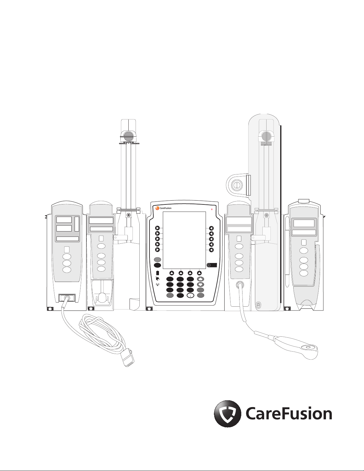
Alaris™ System with Guardrails™ Suite MX
(with Alaris™ PC unit, Model 8015 Software Version 9.33)
February 2017
NI
TO
O
M
R
ST
M
A
R
ND
A
L
A
PULSE (BPM)
B
Y
% SpO
2
A
L
A
M
R
RA TE (mL/h)
F
U
S
N
E
I
ST
A
N
DB
Y
®
Alaris PC
Guardrails
®
A
L
A
M
R
RA TE (mL/h)
U
NF
S
E
I
ST
A
N
DB
Y
U
S
F
E
IN
S
T
A
ND
M
R
A
L
A
RA TE (mL/h)
B
Y
CHANNEL
SELECT
MONITOR
CHANNEL
OFF
CHANNEL
SELECT
PAUSE
CHANNEL
RESTART
CHANNEL
SELECT
OFF
SILENCE
OPTIONS
1
2
4
7
CLEAR
3
5
6
9
8
0
SYSTEM
ON
ENTER
CANCEL
PAUSE
CHANNEL
RESTART
OFF
CHANNEL
SELECT
PAUS E
CHANNEL
OFF
RESTART
Page 2

THIS PAGE
INTENTIONALLY
LEFT BLANK
Page 3

Table of Contents
Each of the Alaris infusion product-specific sections has its own table of contents.
General Contact Information
......................................................................................................iv
Introduction ................................................................................................................................... v
Approved Parts Recommendation .................................................................................. viii
Installation
................................................................................................................................... viii
Alaris PC Unit Model 8015................................................................................... Section 1
Alaris Pump Module, Model 8100 Alaris Syringe Module, Model 8110 ............... Section 2
Alaris PCA Module Model 8120 ........................................................................... Section 3
Alaris SpO
Alaris EtCO
Module Models 8210 and 8220 ........................................................ Section 4
2
Module Model 8300 ........................................................................ Section 5
2
Alaris Auto-ID Module Model 8600 ...................................................................... Section 6
Appendix
Troubleshooting and Maintenance..........................................................................................A-1
Alaris Systems Manager Connections...............................................................................A-2
Alarms and Alerts ..............................................................................................................A-3
Storage ............................................................................................................................A-24
Battery Care and Maintenance ........................................................................................ A-24
Wireless Connection........................................................................................................A-26
Cleaning...........................................................................................................................A-28
Service Information..........................................................................................................A-33
Regulations and Standards...................................................................................................A-35
Compliance......................................................................................................................A-35
Trademarks......................................................................................................................A-46
Order Number:
Printed Copy: P00000158
© 2005-2017 CareFusion Corporation or one of its affiliates. All rights reserved.
Alaris System User Manual – with v9.33 Model 8015 iii
Page 4

General Contact Information
CareFusion
10020 Pacific Mesa Blvd
San Diego, California 92121
United States
Authorized European Representative
CareFusion UK 305 Ltd., The Crescent,
Jays Close, Basingstoke, Hampshire RG22 4BS, UK
Authorized Australian/New Zealand Representative
CareFusion Australia and New Zealand
Unit 3, 167 Prospect Highway
Seven Hills
NSW 2147
Australia
carefusion.com
Customer Advocacy - North America
(Clinical and technical feedback.)
Phone: 888.812.3266 Email: CustomerFeedback@carefusion.com
Customer Advocacy - International
(Clinical and technical feedback.)
Email: cai@carefusion.com
Technical Support - North America
(Maintenance and service information support; troubleshooting.)
Phone, United States: 888.812.3229
Phone, Canada: 800.387.8309
Technical Support - United Kingdom
(Maintenance and service information support; troubleshooting.)
Phone: 0800 389 6972
Email: DL-INTL-Infusion-Tech-Support@Carefusion.com
Customer Order Management - North America
(Product return, service assistance, and order placement.)
Phone, United States: 800.482.4822
Phone, Canada: 800.387.8309
Customer Care - United Kingdom
(Product return, service assistance, and order placement.)
Phone: 0800 917 8776
Email: UK-Customer-Service@carefusion.com
Technical Support and Customer Service - International
(Maintenance and service information support. Product return, service assistance, and order placement)
www.carefusion.com/customer-support/customer-service
Technical Support - Australia/New Zealand
(Maintenance and service information support; troubleshooting, service assistance.)
Phone: 1300 729 258
Email: techservice-au@carefusion.com
iv Alaris System User Manual – with v9.33 Model 8015
Page 5

Introduction
The Alaris™ PC unit section of this User Manual provides
procedures and information applicable to the Alaris System and
the PC unit. Each of the other major sections provides productspecific procedures and information.
The Alaris System is a modular system intended for adult,
pediatric, and neonatal care. It consists of the PC unit, the
Guardrails™ Suite MX, and up to four detachable infusion and/
or monitoring modules (channels). The Alaris Auto-ID module
can be included as a fifth module. The use of the Alaris System
is restricted to one patient at a time.
Guardrails Suite MX for the Alaris System brings a new level of
medication error prevention to the point of patient care. The
Guardrails Suite MX features medication dosing, concentration
delivery rate, and optional initial programming guidelines for up
to 30 patient-specific care areas, referred to as Profiles. Each
Profile contains a specific Drug Library, an IV Fluid library, and
channel labels, as well as instrument configurations
appropriate for the care area. Optional drug- or IV Fluid-specific
Clinical Advisories provide visual messages. Dosing limits for
each Guardrails drug entry or rate limits for each IV Fluid entry
can be a Hard Limit that cannot be overridden during infusion
programming and/or a Soft Limit that can be overridden, based
on clinical requirements.
WARNING
Read all instructions before using
the Alaris System.
CAUTION
nly
O
A Data Set is developed and approved by the facility’s
own multi-disciplinary team using the Guardrails Editor
software, the PC-based authoring tool. A Data Set is then
transferred to the Alaris System by qualified personnel. The
approved Data Sets are maintained by the Editor Software for
future updates and reference.
Information about an Alert that occurs during use is
stored within the PC unit, and can be accessed using the
Guardrails CQI Reporter software.
Documentation provided with Alaris System products
might reference product not present in your facility or not yet
available for sale in your area.
A superscript number (for example,
) identifies additional
information provided as a NOTE at the end of the procedure.
Alaris System User Manual – with v9.33 Model 8015 v
Page 6

Intended Use
Introduction (Continued)
The Alaris™ System with Guardrails™ Suite MX is intended for
use in professional healthcare facilities that utilize infusion
devices for the delivery of fluids, medications, blood, and blood
products. The Alaris System with Guardrails Suite MX is
intended to provide trained healthcare caregivers a way to
automate the programming of infusion parameters, thereby
decreasing the amount of manual steps necessary to enter
infusion data.
All data entry and validation of infusion parameters is
performed by the trained healthcare professional according to a
physician's order. The Alaris System with Guardrails Suite MX
is an interoperable system capable of communicating and
exchanging data accurately, effectively, securely, and
consistently with different information technology systems,
software applications, and networks, in various settings; and
exchanging data such that the clinical or operational purpose
and meaning of the data are preserved and unaltered.
Essential Performance
The Alaris infusion modules are designed to accurately deliver
the programmed amount of the medication or fluid over the
programmed time period. The Alaris infusion modules ensure
that an infusion is not being inadvertently delivered when the
user expects the system to be in a paused, stopped, or off
condition. The Alaris infusion modules employ measurement
systems to detect and alarm for conditions adverse to safe
administration of fluid. These include measurements of proper
infusion set loading (free flow detection), pressure (occlusion
detection), and air-in-line detection.
The EtC0
module will monitor and alarm when a patient
2
physiological condition is out of range.
The Sp0
module will monitor and alarm when a patient
2
physiological condition is out of range
vi Alaris System User Manual – with v9.33 Model 8015
Page 7

Introduction (Continued)
WARNINGS AND CAUTIONS:
Product-specific warnings and cautions, covered in the
applicable sections of this User Manual, provide information
needed to safely and effectively use the Alaris System.
WARNING
A statement that alerts the user to the
possibility of injury, death, or other serious adverse reactions
associated with the use or misuse of the device.
CAUTION
A statement that alerts the user to the
possibility of a problem with the device associated with the use
or misuse of the device.
DEFINED TERMS:
The following table identifies the defined terms used
throughout this document for certain trademarked products
and product features.
Product/Feature Defined Term
Alaris™ Auto-ID module Auto-ID module
Alaris™ EtCO2 module EtCO2 module
Alaris™ PCA module PCA module
Alaris™ PC unit PC unit
Alaris™ Pump module Pump module
Alaris™ SpO2 module SpO2 module
Alaris™ Syringe module Syringe module
Alaris™ System Maintenance System Maintenance
Alaris™ Systems Manager Systems Manager
Guardrails™ alert Alert
Guardrails™ clinical advisory Clinical Advisory
Guardrails™ CQI Reporter CQI Reporter
Guardrails™ data set Data Set
Guardrails™ drug library Drug Library
Guardrails™ Editor Editor Software
Alaris System User Manual – with v9.33 Model 8015 vii
Page 8

Introduction (Continued)
Product/Feature Defined Term
Guardrails™ hard limit Hard Limit
Guardrails™ IV fluid IV Fluid
Guardrails™ limit Limit
Guardrails™ PCA pause
protocol
Guardrails™ soft limit Soft Limit
SmartSite™ needle-free valve Needle-Free Valve
PCA Pause Protocol
Approved Parts Recommendation
CareFusion recommends the use of CareFusion manufactured
parts in the operation and maintenance of your CareFusion
equipment. Customer's use of repair or service parts, add-ons,
or disposables that are not approved by CareFusion is at
Customer's own risk and may void the product warranty
provided by CareFusion. Any 510(k) clearance from the Food
and Drug Administration (FDA) or regulatory approval secured
by CareFusion to market Alaris pumps was based on use of
only CareFusion manufactured parts and equipment. If nonCareFusion parts, add-ons or disposables are used for the
maintenance, repair or operation of your CareFusion
equipment, those parts were not validated by CareFusion for
safety and efficacy with our Alaris products, nor were they
included in the review and approval/clearance of the products.
Installation
Instruments are tested and calibrated before they are
packaged for shipment. To ensure proper operation after
shipment, it is recommended that an incoming inspection be
performed before placing the instrument in use.
Prior to placing the Alaris System in use:
1. Perform check-in procedure using System Maintenance
software.
2. Whether or not Profiles feature has been enabled
(see PC unit section, "System Options," "System
Configurations").
NOTE:
To enable the Profiles feature, a hospital-defined best-practice
Data Set must be uploaded to the PC unit.
viii Alaris System User Manual – with v9.33 Model 8015
Page 9
Alaris PC Unit
Model 8015
Alaris System User Manual – with v9.33 Model 8015 Section 1
Page 10

THIS PAGE
INTENTIONALLY
LEFT BLANK
Page 11

Table of Contents
Getting Started
Introduction............................................................................................................................................. 1-1
General Setup and Operation
Attach and Detach Module..................................................................................................................... 1-3
Attach Module................................................................................................................................. 1-3
Detach Module ............................................................................................................................... 1-4
Add Module While System is Powered On..................................................................................... 1-5
Start-Up.................................................................................................................................................. 1-6
Power On System........................................................................................................................... 1-6
Respond to Maintenance Reminder ............................................................................................... 1-7
Adjust Display Contrast .................................................................................................................. 1-7
Select New Patient and Profile Options.......................................................................................... 1-8
Adjust Audio Volume ...................................................................................................................... 1-10
Lock/Unlock Tamper Resist............................................................................................................ 1-11
Power Off System .................................................................................................................................. 1-12
System Options...................................................................................................................................... 1-13
Display Contrast ............................................................................................................................. 1-13
Patient ID........................................................................................................................................ 1-13
Clinician ID ..................................................................................................................................... 1-16
Power Down All Channels .............................................................................................................. 1-17
Anesthesia Mode............................................................................................................................ 1-18
Battery Runtime.............................................................................................................................. 1-21
System Configurations ................................................................................................................... 1-21
Serial Numbers............................................................................................................................... 1-23
Software Versions .......................................................................................................................... 1-24
Time of Day .................................................................................................................................... 1-25
Network Status ............................................................................................................................... 1-26
Wireless Connection....................................................................................................................... 1-29
Data Set Status .............................................................................................................................. 1-30
Maintenance Due ........................................................................................................................... 1-31
General Information
Warnings and Cautions.......................................................................................................................... 1-33
General........................................................................................................................................... 1-33
Electromagnetic Compatibility ........................................................................................................ 1-36
Features and Displays............................................................................................................................ 1-37
Features and Definitions................................................................................................................. 1-37
Operating Features, Controls, Indicators........................................................................................ 1-39
Displays .......................................................................................................................................... 1-42
System Configurable Settings................................................................................................................ 1-43
Specifications ................................................................................................................................. 1-44
Symbols.......................................................................................................................................... 1-46
PC Unit Section Table of Contents
Alaris System User Manual – with v9.33 Model 8015 1-iii
Page 12

THIS PAGE
INTENTIONALLY
LEFT BLANK
Table of Contents PC Unit Section
1-iv Alaris System User Manual – with v9.33 Model 8015
Page 13

Introduction
Getting Started
This section of the User Manual provides PC unit (Model
8015) and Alaris
System instructions and information. It is used
in conjunction with:
• PC Unit/ Pump Module Technical Service Manual
• Product-specific sections of this User Manual
• System Maintenance software (and its instructions) for
Alaris System check-in, maintenance, and wireless configuration
The PC unit is the core of the Alaris System and provides
a common user interface for programming infusions and
monitoring, which helps to reduce complexity at the point of
care. The display uses color to clearly communicate critical
programming, infusion, monitoring and hospital-defined policy
information.
The wireless network card provides wireless communication
capability between the Alaris System and Alaris Systems
Manager. The combined use of the Alaris System and Alaris
Systems Manager is integrated into a facility’s existing network
infrastructure.
When enabled, the Alaris Systems Manager allows the
exchange of information between the Alaris Systems Manager
and the Alaris System. The PC unit can be operated
manually or in concert with the information exchanged with the
Alaris Systems Manager. If communication with the wireless
network is interrupted (for example, out of range), the Alaris
System can be used, as intended, in the manual mode.
WARNING
Read all instructions, including those
for the attached module(s) and
applicable accessories, before using
the Alaris System.
CAUTION
nly
O
PC Unit Section Getting Started
Alaris System User Manual – with v9.33 Model 8015 1-1
Page 14

Introduction (Continued)
Alarms and Alerts: See "Appendix A - Troubleshooting and
Maintenance" for specific PC unit alarms and alerts.
Contraindications: None known.
Electromagnetic Environment: See "Appendix" section
of this User Manual ("Regulations and Standards,"
"Compliance").
Getting Started PC Unit Section
1-2 Alaris System User Manual – with v9.33 Model 8015
Page 15

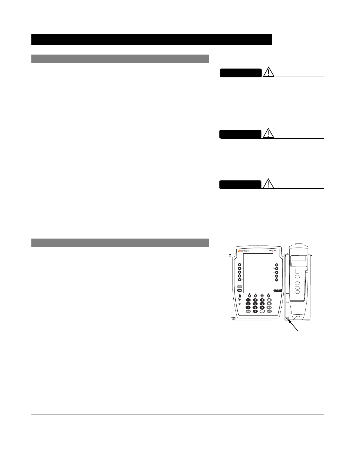
General Setup and Operation
Attach and Detach Module
Modules can be attached to either side of the PC unit or to
either side of another module. The process to attach or detach
is the same for either side, whether attaching/detaching
to/from a PC unit or another module.
An individual hospital/facility can choose to permanently attach
modules. To remove permanently attached modules, contact
qualified service personnel.Inserting a finger or other object
into the IUI connector, when the module is attached to the PC
unit, could result in electrical shock.
WARNING
Attach Module
The Alaris System is designed to operate a maximum of
four infusion or monitoring modules. Modules added in excess
of four are not recognized by the system. The Auto-ID module
can be included as a fifth module. A module can be attached
in any position; however, when mounted on an IV pole, it is
recommended that a balanced configuration be maintained.
Application of adhesive tape or other materials to the sides of
the PC unit and modules can prevent proper latching.
1. Position free module at a 45° angle, aligning IUI
connectors.
IUI Connector
Inserting a finger or other object into
the IUI connector, when the module
is attached to the PC unit, could
result in electrical shock.
Aligned IUI Connectors
Top View
45°
IUI Connectors Not Aligned
Front View
Top View
PC Unit Section General Setup and Operation
Alaris System User Manual – with v9.33 Model 8015 1-3
Page 16
Attach and Detach Module (Continued)
Attach Module (Continued)
2. Rotate free module down against PC unit or attached
module until release latch snaps in place.
WARNING
When properly secured/snapped, the
release latch provides a very secure
connection between modules. If not
properly latched, a module can be
dislodged during operation.
WARNING
Failure to perform these operations
can result in improper instrument
operations.
WARNING
Failure to follow these instructions
may result in potential hazards
associated with damaged IUI
connectors.
Detach Module
1. Ensure that module is powered off before detaching.
2. Push module release latch and then rotate module up
and away from PC unit or attached module (opposite to
motion shown in "Attach Module" procedure) to disengage
connectors.
• Alaris System reidentifies and shows appropriate
module identification (A, B, C, or D), from left to right.
• Appropriate module position(s) (A, B, or C) for
remaining module(s) appear on Main Display.
Release Latch
General Setup and Operation PC Unit Section
1-4 Alaris System User Manual – with v9.33 Model 8015
Page 17

Attach and Detach Module (Continued)
Add Module While System is Powered On
Add module as described in "Attach Module."
• System tests module, causing all LED segments and
indicator lights of displays to illuminate briefly.
• Appropriate module identification display (A, B, C, or D)
illuminates. Modules are always labeled left to right, so if
a module is added to left of other modules, all modules are
reidentified. Module re-identification does NOT interrupt or
affect infusion or monitoring on active modules.
• Module positions (A, B, C, or D) appear on Main Display.
• If any of the following conditions are observed, affected
module must be removed from use and inspected by
qualified personnel:
◦ LED segments are not illuminated on displays during
power-on test.
◦ Indicator lights do not illuminate.
◦ Appropriate module identification does not appear.
PC Unit Section General Setup and Operation
Alaris System User Manual – with v9.33 Model 8015 1-5
Page 18

Start-Up
Power On System
1. Connect PC unit to an external AC power source.
2. Press
SYSTEM ON key.
3. System self test begins:
• Diagnostics test causes all LED display segments
and Status Indicator lights of attached module(s) to
illuminate briefly.
• Power Indicator illuminates.
• Appropriate module identification (A, B, C, or D) is
displayed on attached module(s).
• An audio tone sounds.
• If PM Reminder option is enabled and scheduled
preventive maintenance is due,
REMINDER screen appears.
• At completion of system-on test,
MAINTENANCE
New Patient? screen
appears.
• If either of the following conditions is observed, PC unit
or affected attached module must be removed from
use and inspected by qualified personnel:
◦ System fails any part of self test.
◦ Main Display does not appear backlit, appears
irregular, or has evidence of a row of pixels not
functioning properly.
NOTE:
Previous infusion parameters are automatically cleared after
8 hours.
The self test provides the clinician with verification of the
operational safety and correct functioning of alarms for the
Alaris System.
General Setup and Operation PC Unit Section
1-6 Alaris System User Manual – with v9.33 Model 8015
Page 19
Start-Up (Continued)
Respond to Maintenance Reminder
If the
Preventive Maintenance (PM) Reminder option is enabled
and the PC unit or an attached module is due for preventive
maintenance, a
at power up. If necessary, the reminder can be temporarily
bypassed by pressing the
1. Notify the appropriate facility personnel when a
MAINTENANCE REMINDER occurs and remove instrument
requiring maintenance (see "Attach and Detach Module").
2. If Alaris System was powered off to replace PC unit,
reinitiate start-up process.
OR
MAINTENANCE REMINDER message appears
CONFIRM soft key.
MAINTENANCE REMINDER
Module(s) due for routine
B
preventive maintenance:
Module A:
YYYY-MM-DD
CONFIRM
If an attached module (such as a Pump module) was
powered off and removed,
MAINTENANCE REMINDER
display reflects removal of that module. To continue
start-up process, press
CONFIRM soft key.
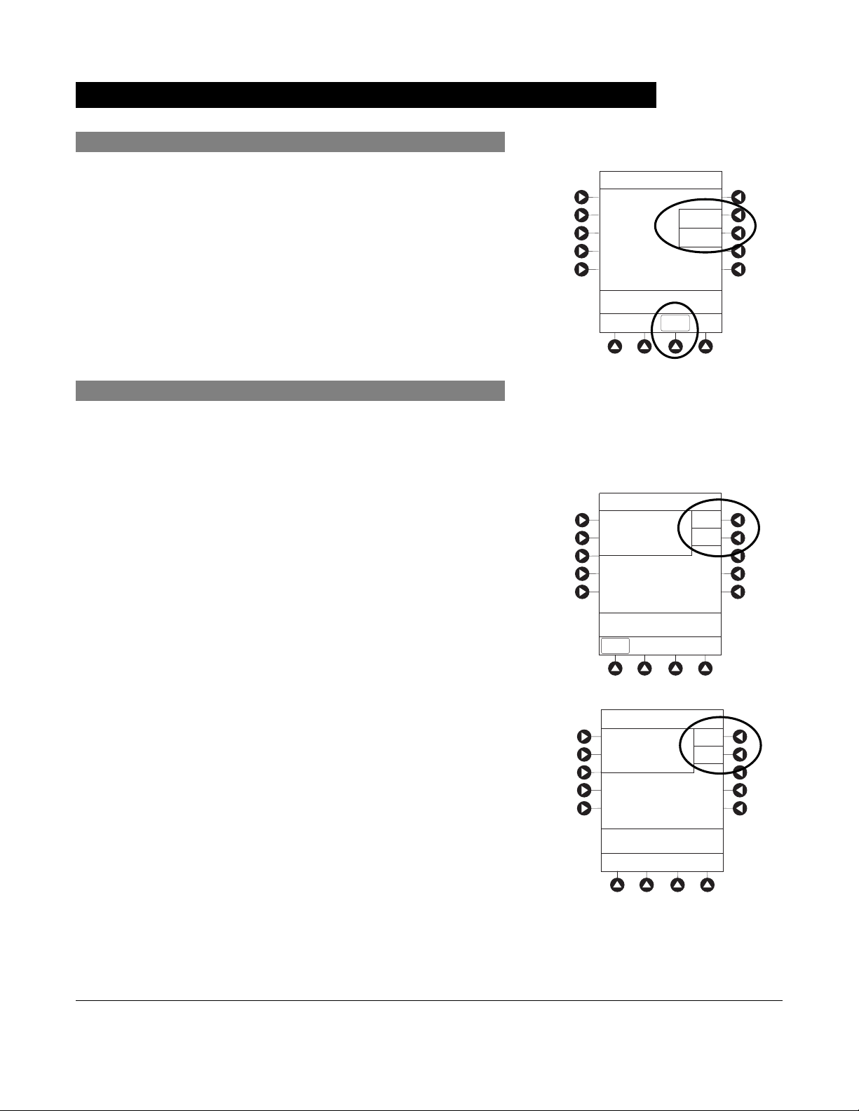
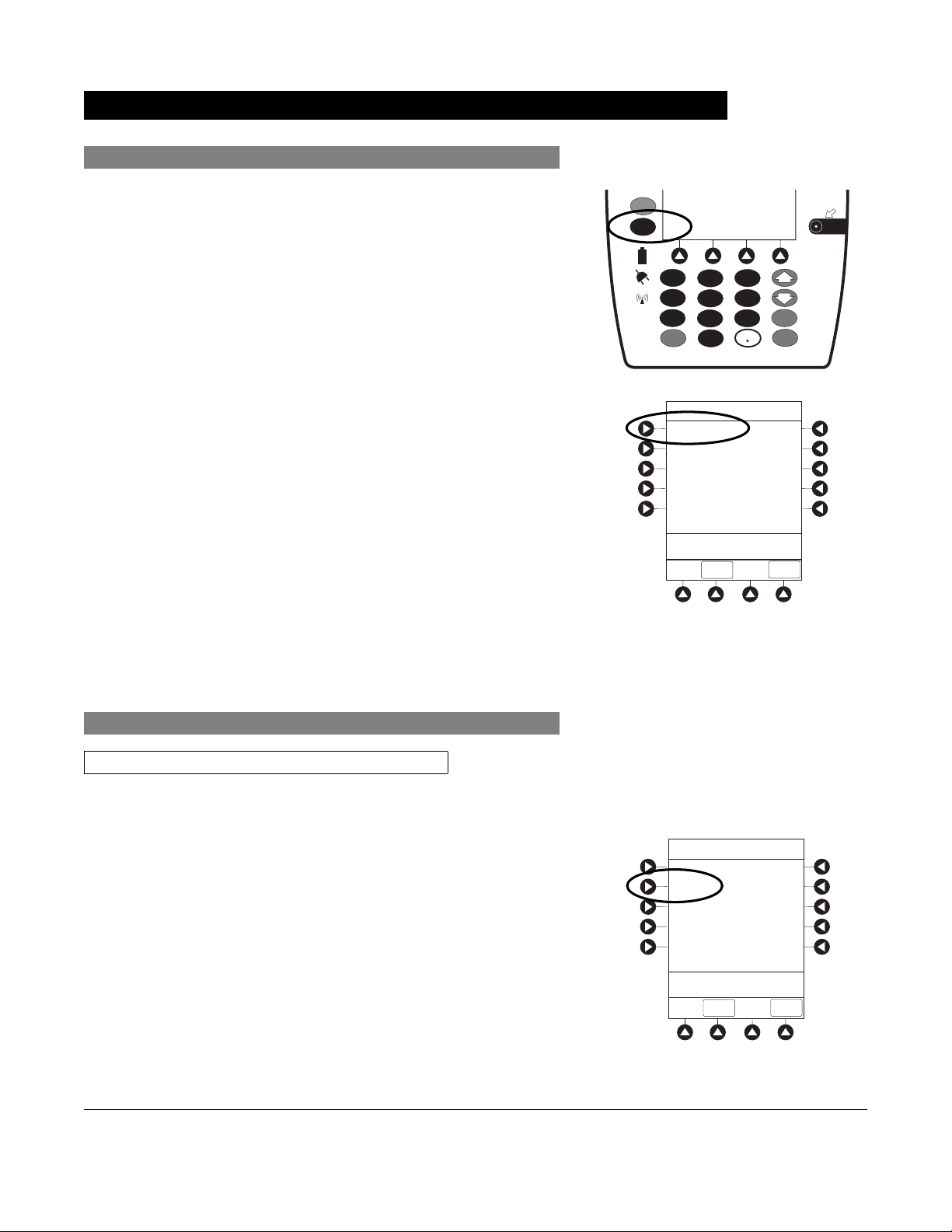
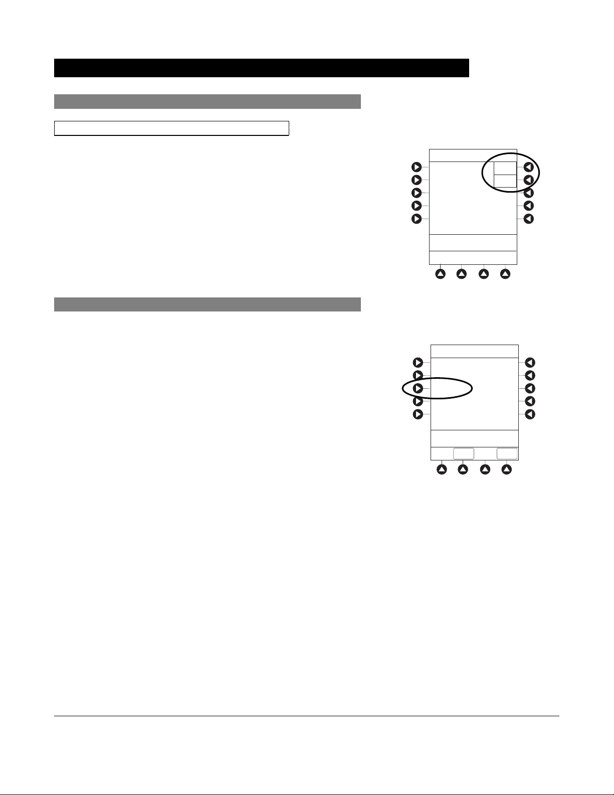
Adjust Display Contrast
1. Press
DISPLAY CONTRAST soft key.
MAINTENANCE REMINDER
Module(s) due for routine
B
preventive maintenance:
CONFIRM
Midtown Hospital
NEW PATIENT ?
“Yes” Clears Previous
Patient Data
>Select Yes or No
DISPLAY
CONTRST
Yes
No
PC Unit Section General Setup and Operation
Alaris System User Manual – with v9.33 Model 8015 1-7
Page 20
Start-Up (Continued)
Adjust Display Contrast (Continued)
2. To adjust display for optimum viewing, use Lighter/Darker
soft keys.
3. To return to main screen, press
CONFIRM soft key.
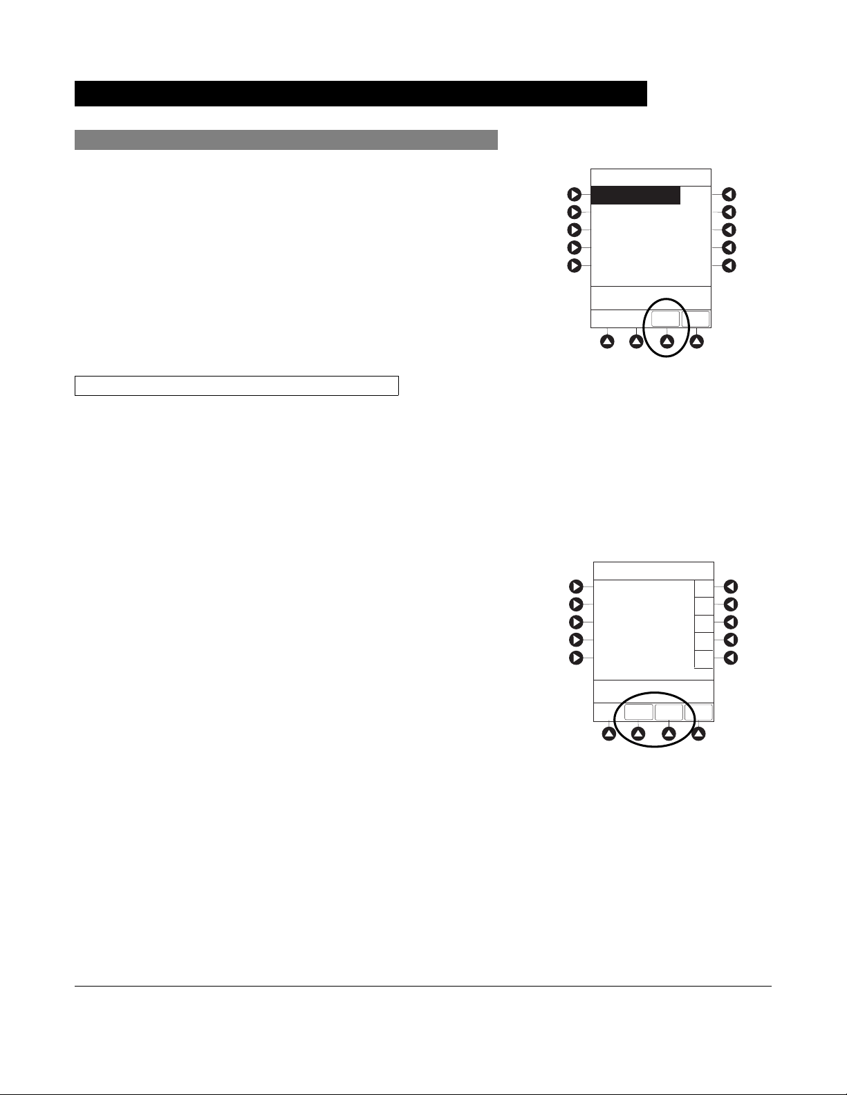
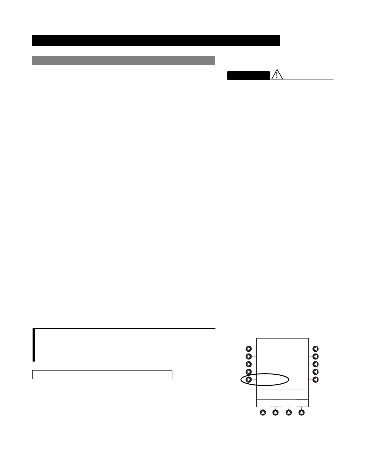
Select New Patient and Profile Options
The following procedures assume the Profiles feature is
enabled.
1. Select required
NEW PATIENT? option.
• To indicate programming is for a new patient and clear
all stored patient parameters from memory, press Yes
soft key.
• To confirm programming is for same patient and retain
all stored patient parameters, press No soft key.
System Options
Display Contrast
®
>Adjust Display to
Desired Contrast
CONFIRM
Midtown Hospital
NEW PATIENT ?
“Yes” Clears Previous
Patient Data
Lighter
Darker
Yes
No
◦ Last used Profile is displayed.
◦ If Profiles feature is disabled, main menu appears.
2. Accept or change current Profile:
• To accept current Profile, press Yes soft key.
Main screen appears.
• To change Profile, press No soft key and continue with
next step.
Profile selection screen appears.
>Select Yes or No
DISPLAY
CONTRST
Midtown Hospital
Adult ICU
Adult ICU ?
“Yes” Confirms Same
Profile
>Select Yes or No
Yes
No
General Setup and Operation PC Unit Section
1-8 Alaris System User Manual – with v9.33 Model 8015
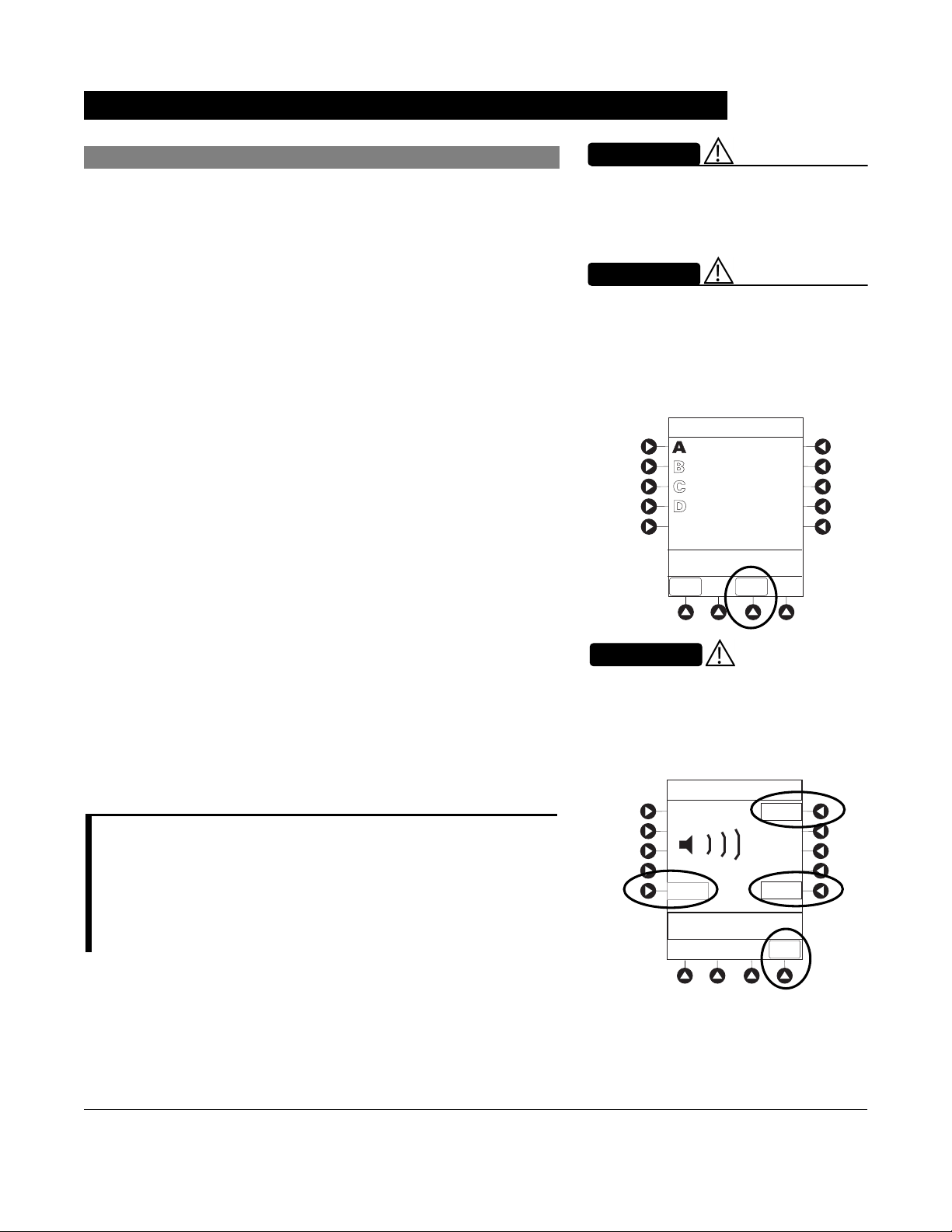
Page 21
Start-Up (Continued)
Select New Patient and Profile Options (Continued)
3. To select a Profile, press corresponding left soft key.
To view additional choices, press
4. To confirm Profile selection, press
PAGE DOWN soft key.
CONFIRM soft key.
Main screen appears.
Patient ID Entry Feature
The option to enter and display a 16-character alphanumeric
patient identifier is always available. The instrument can be
configured to automatically display the Patient ID Entry
screen during start-up or to provide access only through the
Systems Options menu (see "System Options").
If Yes was selected to indicate programming for a new patient,
perform one of following steps:
• If patient identifier is not required, press
CONFIRM or EXIT
soft key.
• To manually enter patient identifier, use numeric data entry
keys and/or alpha speed keys.
◦ An alphanumeric identifier, of up to 16 characters, can
be entered.
◦ Press soft key next to a letter group to list letters in
that group. Press soft key next to an individual letter to
enter that letter.
Midtown Hospital
Profiles
Adult ICU
Adult General Care
Neonatal
Peds ICU
Neonatal ICU
>Press CONFIRM
Patient ID Entry
A
B
C
D
E
_ _ _ _ _ _ _ _ _ _ _ _ _ _ _ _
>Enter Patient ID and Press
CONFIRM
EXIT
CONFIRM
CONFIRM
1 of 2
PAGE
DOWN
PAGE
DOWN
A-E
F-J
K-O
P-T
U-Y
◦ To access letter "Z" and special characters (hyphen,
underscore, space), press
◦ To clear an entire entry, press
◦ To back up a single character at a time, press
PAGE DOWN soft key.
CLEAR key.
CANCEL
key.
• To scan barcode on patient identification band,
see"Alaris Auto-ID Module Model 8600", section 6 of this
User Manual.
PC Unit Section General Setup and Operation
Alaris System User Manual – with v9.33 Model 8015 1-9
Page 22
A
p
Start-Up (Continued)
Adjust Audio Volume
1. Press AUDIO ADJUST soft key.
WARNING
The user should check that the
current alarm preset is appropriate
prior to use on each patient.
WARNING
hazard can exist if different Alarm
Presets are used for the same or
similar equipment in a single area,
such as an Intensive Care Unit or a
Cardiac O
erating Theatre.
Midtown Hospital
Adult ICU
VTBI = 250.0 mL
VOLUME
INFUSED
AUDIO
ADJUST
2. To change volume to desired level, press either Louder
or Softer soft key. To sample alarm loudness level, press
Test soft key.
3. To return to PC unit screen, press
MAIN SCREEN soft key.
After 30 seconds without a key press, Main Display
appears.
NOTE:
The Minimum Audio Volume defaults to level 1. Levels 1-5 may be
set per profile. The user is able to lower the device AUDIO
VOLUME to the minimum limit set. When the minimum AUDIO
VOLUME LEVEL has been reached, the Louder/Softer soft keys
are unavailable and the PC unit emits an illegal key press audio.
CAUTION
Setting the audio volume to the
lowest level will lower all system
alarms, including secondary alarms
such as End of Infusion.
Audio Volume Adjust
Test
3
Softer
>Change Setting or
Cancel
Louder
MAIN
SCREEN
General Setup and Operation PC Unit Section
1-10 Alaris System User Manual – with v9.33 Model 8015
Page 23
Start-Up (Continued)
Lock/Unlock Tamper Resist
1. Initiate operation of applicable module.
2. Press and hold Tamper Resist Switch, on back of PC unit,
for 3 to 4 seconds (see "General Information," "Features
and Displays," "Operating Features, Controls, Indicators").
• An advisory tone (if Key Click Audio is enabled)
and a three-second
PANEL LOCKED prompt on Main
Display confirm activation.
• When Tamper Resist is active, keypad panel is locked;
however, clinician can:
◦ Silence audio alarm.
◦ View volume(s) infused.
◦ View and test audio alarm setting.
◦ View selected parameters on attached modules.
Any other key press results in a visual
PANEL LOCKED
prompt and, if Key Click Audio is enabled, an illegal
key–press audio advisory.
3. To unlock keypad panel, press and hold Tamper Resist
Switch for 3 to 4 seconds.
An advisory tone (if Key Click Audio is enabled) and a
three-second
PANEL UNLOCKED prompt on Main Display
confirm activation.
Midtown Hospital
Adult ICU
VTBI = 250.0 mL
PANEL LOCKED
VOLUME
INFUSED
Midtown Hospital
Adult ICU
VTBI = 250.0 mL
AUDIO
ADJUST
PANEL UNLOCKED
VOLUME
INFUSED
AUDIO
ADJUST
PC Unit Section General Setup and Operation
Alaris System User Manual – with v9.33 Model 8015 1-11
Page 24
Power Off System
Press and hold CHANNEL OFF key until a beep is heard
(approximately 1.5 seconds) and then release to initiate power
down.
• During power off sequence, Main Display flashes
Powering Down.
• To interrupt power down sequence, quickly press any key
(except
Once all attached modules are powered off, PC unit
automatically powers down.
SYSTEM ON) on PC unit.
Powering Down
General Setup and Operation PC Unit Section
1-12 Alaris System User Manual – with v9.33 Model 8015
Page 25
System Options
Display Contrast
1. Press OPTIONS key.
2. Press Display Contrast soft key.
3. Adjust display and return to main screen (see Start-Up,"
Adjust Display Contrast" procedure).
SILENCE
OPTIONS
1
2
4
5
7
8
CLEAR
0
System Options 1 of 3
Display Contrast
Patient ID
Clinician ID
Power Down All Channels
Anesthesia Mode
>Select an Option or
EXIT
EXIT
SYSTEM
ON
3
6
ENTER
9
CANCEL
PAGE
DOWN
Patient ID
Enter
1. Press
2. Press Patient ID
PC Unit Section General Setup and Operation
Alaris System User Manual – with v9.33 Model 8015 1-13
OPTIONS key.
soft key.
System Options 1 of 3
Display Contrast
Patient ID
Clinician ID
Power Down All Channels
Anesthesia Mode
>Select an Option or
EXIT
EXIT
PAGE
DOWN
Page 26
System Options (Continued)
Patient ID (Continued)
Enter (Continued)
3. Scan or manually enter patient identifier:
• To manually enter patient identifier, use numeric data
entry keys and/or alpha speed keys.
◦ An alphanumeric identifier, of up to
16 characters,
can be entered.
◦ Press soft key next to a letter group to list letters
in that group. Press soft key next to an individual
letter to enter that letter.
◦ To access letter "Z" and special characters
(hyphen, underscore, space), press
PAGE DOWN
soft key.
◦ To clear an entire entry, press
CLEAR key.
◦ To back up a single character at a time, press
CANCEL key.
• To scan barcode on patient identification band, see
AUTO-ID section of this User Manual.
4. To verify correct entry, press
CONFIRM soft key.
Patient ID Entry
CONFIRM
A-E
F-J
K-O
P-T
U-Y
PAGE
DOWN
A
B
C
D
E
123456789CD_ _ _ _ _
>Enter Patient ID and Press
CONFIRM
EXIT
General Setup and Operation PC Unit Section
1-14 Alaris System User Manual – with v9.33 Model 8015
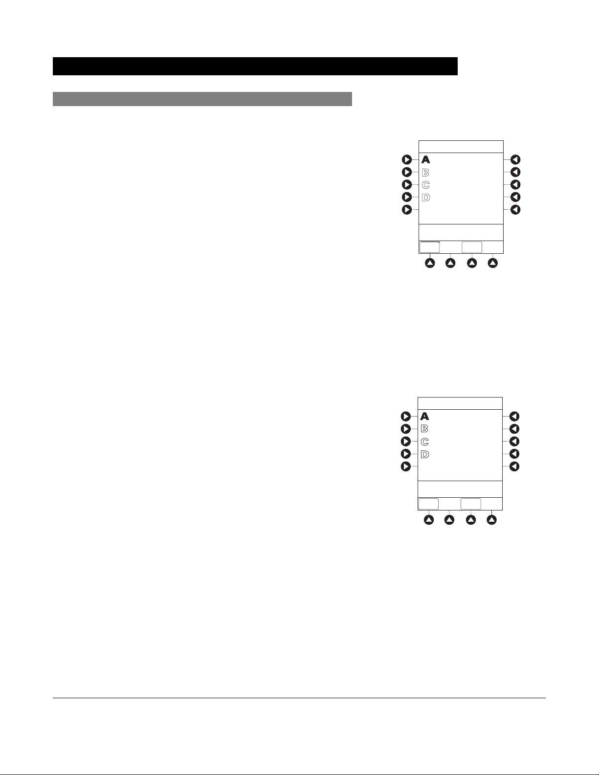
Page 27
SILENCE
Modify
System Options (Continued)
Patient ID (Continued)
1. Press
OPTIONS key.
2. Press Patient ID soft key.
3. To clear entire entry, press
OR
CLEAR key.
To back up a single character at a time, press CANCEL
key.
4. To enter modified patient identifier, use numeric data entry
keys and/or alpha speed keys.
• An alphanumeric identifier, of up to 16 characters, can
be entered.
• Press soft key next to a letter group to list letters in
that group. Press soft key next to an individual letter to
enter that letter.
OPTIONS
1
4
7
CLEAR
SYSTEM
ON
2
3
5
6
ENTER
9
8
0
CANCEL
OR
• To access letter "Z" and special characters (hyphen,
underscore, space), press
5. To verify correct entry, press
New Patient ID Entry verification screen appears.
PC Unit Section General Setup and Operation
Alaris System User Manual – with v9.33 Model 8015 1-15
PAGE DOWN soft key.
CONFIRM soft key.
Patient ID Entry
CONFIRM
A-E
F-J
K-O
P-T
U-Y
PAGE
DOWN
A
B
C
D
E
234567891EF_ _ _ _ _
>Enter Patient ID and Press
CONFIRM
EXIT
Page 28
Modify (Continued)
System Options (Continued)
Patient ID (Continued)
6. To accept modified Patient ID, press Yes soft key.
Main screen appears with new Patient ID.
OR
To retain original (old) Patient ID, press No soft key.
Main screen appears with old Patient ID.
Clinician ID
1. Press
OPTIONS key.
2. Press Clinician ID soft key.
Patient ID Entry
Patient ID
123456789CD
will be changed to
234567891EF
Is this correct?
>Press Yes or No
System Options 1 of 3
Display Contrast
Patient ID
Clinician ID
Power Down All Channels
Anesthesia Mode
>Select an Option or
EXIT
EXIT
Yes
No
PAGE
DOWN
3. Scan or manually enter clinician identifier:
To manually enter clinician identifier, use numeric data
entry keys and/or alpha speed keys.
• An alphanumeric identifier, of up to 16 characters, can
be entered.
• Press soft key next to a letter group to list letters in
that group. Press soft key next to an individual letter to
enter that letter.
• To access letter "Z" and special characters (hyphen,
underscore, space), press
• To clear an entire entry, press
• To back up a single character at a time, press
PAGE DOWN soft key.
CLEAR key.
CANCEL
key.
General Setup and Operation PC Unit Section
1-16 Alaris System User Manual – with v9.33 Model 8015
Page 29

System Options (Continued)
Clinician ID (Continued)
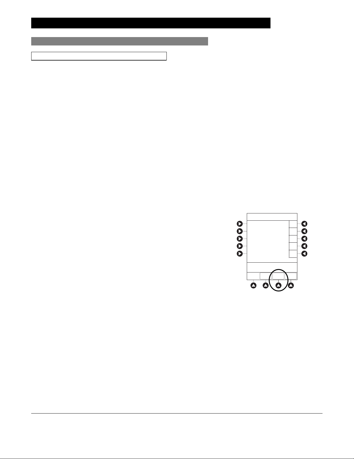
4. To verify correct entry, press CONFIRM soft key.
Power Down All Channels
1. Press
OPTIONS key.
2. Press Power Down All Channels soft key.
Clinician ID Entry
CONFIRM
PAGE
DOWN
PAGE
DOWN
A-E
F-J
K-O
P-T
U-Y
A
B
C
D
E
123456789CD_ _ _ _ _
>Enter Clinician ID and Press
CONFIRM
EXIT
System Options 1 of 3
Display Contrast
Patient ID
Clinician ID
Power Down All Channels
Anesthesia Mode
>Select an Option or
EXIT
EXIT
3. Press Yes soft key.
During power off sequence, Main Display flashes
POWERING DOWN.
System Options
Power Down
All Channels?
>Press Yes or No
Yes
No
PC Unit Section General Setup and Operation
Alaris System User Manual – with v9.33 Model 8015 1-17
Page 30
System Options (Continued)
Anesthesia Mode
When the Anesthesia Mode is enabled and then the pause
feature is used - the module remains in an indefinite pause until
restarted.
When Anesthesia Mode is enabled:
• A channel can be paused indefinitely without an alarm.
• The air-in-line associated with the Profile can be set up to
500 micro liters.
• All limits are set to Soft.
• Limit Checking mode is set to Smart.
• Key-press audio is turned off.
• Auto-Restart for Anesthesia Mode is set to 9 and is not
configurable.
• Panel Lock through Tamper Resist Mode or Authorized
User Mode is not available.
• Guardrails drug list defaults to drugs designated by Editor
Software as anesthesia only. All Guardrails drugs in a
Profile can be viewed by pressing ALL DRUGS soft key.
• Bolus Dose is automatically available for:
WARNING
When the Alaris System is set up for
use in Anesthesia Mode, it is
important to select the Profile that
corresponds with the care area the
patient will be taken to when the
Anesthesia Mode is discontinued.
This ensures that the Alaris System
will be in the correct Profile following
the use of the Anesthesia Mode.
◦ Guardrails drugs that have Bolus Dose limits defined
◦ generic drug calculation setup
• Anesthesia Mode, alternating with other required prompts,
is displayed in prompt bar of Main Display.
• Callback audio for paused module is permanently silenced.
• Review of drug calculation setup page is omitted when
restoring a stopped drug calculation.
• Clinical Advisories are not displayed.
NOTE:
If an infusion is paused in regular mode and then the anesthesia
mode is enabled - the device will alarm at the 2 minute warning.
Enable
1. Press
OPTIONS key.
System Options 1 of 3
Display Contrast
Patient ID
Clinician ID
Power Down All Channels
Anesthesia Mode
>Select an Option or
EXIT
EXIT
PAGE
DOWN
General Setup and Operation PC Unit Section
1-18 Alaris System User Manual – with v9.33 Model 8015
Page 31

System Options (Continued)
Anesthesia Mode (Continued)
Enable (Continued)
2. Press Anesthesia Mode soft key.
3. Press Enable soft key.
4. Press
CONFIRM soft key.
Disable
The Anesthesia Mode can be disabled, and normal operation
resumed, using either of the following three methods:
• System Options menu.
• Disconnecting from AC power.
• Connecting to AC power.
From System Options Menu
1. Press
OPTIONS key.
System Options
Anesthesia Mode
Enable
Disable
Pump Module
Air Detection =
microliters
75
>Select an Option or Press
CONFIRM
Change
CONFIRM
2. Press Anesthesia Mode soft key.
3. Press Disable soft key.
4. Press
CONFIRM soft key.
Anesthesia Mode no longer appears on Main Display,
indicating it has been disabled.
PC Unit Section General Setup and Operation
Alaris System User Manual – with v9.33 Model 8015 1-19
Page 32

System Options (Continued)
Anesthesia Mode (Continued)
Disable (Continued)
Connect to AC Power
1. Connect system to AC power.
2. To continue using Anesthesia Mode, press Yes soft key.
OR
To discontinue Anesthesia Mode, press No soft key.
AC power cord was
connected.
Continue
>Select Yes or No
Yes
No
?ANESTHESIA MODE
Disconnect from AC Power
1. Disconnect system from AC.
• Anesthesia Mode is automatically disabled.
• All currently running infusions continue.
• A prompt appears as an alert that Anesthesia Mode
has been discontinued.
2. Press
CONFIRM soft key.
Anesthesia mode was
when AC power
disconnected.
continue normal operation.
>Press CONFIRM
discontinued
cord was
Press CONFIRM to
CONFIRM
General Setup and Operation PC Unit Section
1-20 Alaris System User Manual – with v9.33 Model 8015
Page 33

Battery Runtime
1. Press OPTIONS key.
System Options (Continued)
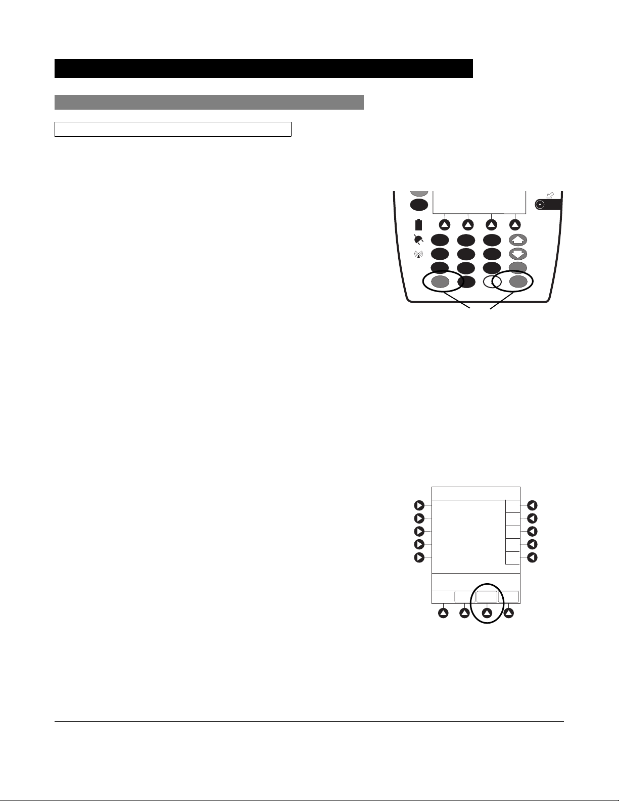
2. Press
PAGE DOWN soft key.
3. Press Battery Runtime soft key.
4. To return to main screen, press
CANCEL key or EXIT soft
key.
System Options 2 of 3
Battery Runtime
System Configurations
Serial Numbers
Software Versions
Time of Day
>Select an Option or
EXIT
PAGE UP
EXIT
System Options
Estimated battery
runtime at current
operating parameters
PAGE
DOWN
9.5 hours
>Press CANCEL or EXIT
EXIT
System Configurations
1. Press OPTIONS key.
2. Press
3. Press System Configuration soft key.
PC Unit Section General Setup and Operation
Alaris System User Manual – with v9.33 Model 8015 1-21
PAGE DOWN soft key.
System Options 2 of 3
Battery Runtime
System Configurations
Serial Numbers
Software Versions
Time of Day
>Select an Option or
EXIT
PAGE UP
EXIT
PAGE
DOWN
Page 34

System Options (Continued)
4. Press PC Unit soft key.
5. To review various system configuration settings, press
PAGE DOWN and PAGE UP soft keys.
System Configuration - Module
Factory Default:
Shared Infusion Settings
PC Unit
Pump Module
SPO2 Module
>Press CANCEL or EXIT
EXIT
System Config - PCU 1 of 3
Alarm audio:
Anesthesia Mode: Disabled
Battery meter:
Clock setup:
Limit Checking:
>Press CANCEL or EXIT
EXIT
Yes
PAGE
DOWN
Profile 1
Disabled
09:00
ALWAYS
PAGE
DOWN
System Config - PCU 2 of 3
Key click audio:
Max Pt. BSA:
Max Pt. weight:
Patient ID Entry:
>Press CANCEL or EXIT
PAGE
EXIT
UP
Enabled
2
2 m
500 kg
Disabled
PAGE
DOWN
General Setup and Operation PC Unit Section
1-22 Alaris System User Manual – with v9.33 Model 8015
Page 35

System Options (Continued)
System Configurations (Continued)
6. To return to main screen, press CANCEL key or EXIT soft
key.
NOTE:
The Profiles option is listed only if it is disabled.
The Limit Checking and Max Pt. BSA options are listed only if
the Profiles option is enabled and a valid Data Set is loaded.
Serial Numbers
1. Press
OPTIONS key.
System Config - PCU 3 of 3
PM Reminder:
Tamper resist:
>Press CANCEL or EXIT
PAGE
EXIT
UP
Disabled
Disabled
2. Press
PAGE DOWN soft key.
3. Press Serial Numbers soft key.
Serial numbers for PC unit and all attached modules
display.
System Options 2 of 3
Battery Runtime
System Configurations
Serial Numbers
Software Versions
Time of Day
>Select an Option or
EXIT
PAGE UP
EXIT
PAGE
DOWN
PC Unit Section General Setup and Operation
Alaris System User Manual – with v9.33 Model 8015 1-23
Page 36

System Options (Continued)
Serial Numbers (Continued)
4. To return to main screen, press EXIT soft key.
NOTE:
"nnnn-nnnnnnnn" in the illustrated display represents a model
and serial number.
Software Versions
1. Press
2. Press
OPTIONS key.
PAGE DOWN soft key.
3. Press Software Versions soft key.
Serial Number Review
PC Unit:
Module A:
Module B:
Module C:
Module D:
>Press CANCEL or EXIT
System Options 2 of 3
Battery Runtime
System Configurations
Serial Numbers
Software Versions
Time of Day
nnnn-nnnnnnnn
nnnn-nnnnnnnn
nnnn-nnnnnnnn
nnnn-nnnnnnnn
nnnn-nnnnnnnn
EXIT
>Select an Option or
4. To review software version information, press View soft
key next to applicable module.
OR
To return to main screen, press EXIT soft key.
EXIT
PAGE UP
EXIT
Software Rev. Review
PC Unit:
Module A:
Module B:
Module C:
Module D:
>Select an Option or
EXIT
EXIT
PAGE
DOWN
View
View
View
View
View
OR
General Setup and Operation PC Unit Section
1-24 Alaris System User Manual – with v9.33 Model 8015
Page 37

System Options (Continued)
Software Versions (Continued)
5. To return to previous screen, press EXIT soft key.
NOTE:
"nn.nn" in the illustrated display represents a software
version.
Time of Day
1. Press OPTIONS key.
2. Press
PAGE DOWN soft key.
Software Rev. Review
Module Software: A
Main processor:
Main boot block:
Keyboard:
>Press CANCEL or EXIT
EXIT
nn.nn
nn.nn
nn.nn
3. Press Time of Day soft key.
4. If time is correct, press
OR
CONFIRM soft key.
To change time, press Change Time soft key.
System Options 2 of 3
Battery Runtime
System Configurations
Serial Numbers
Software Versions
Time of Day
>Select an Option or
EXIT
PAGE UP
EXIT
System Options
Time of Day
Current time:
09:00
>CONFIRM Time-of-Day
EXIT
CONFIRM
PAGE
DOWN
Change
Time
PC Unit Section General Setup and Operation
Alaris System User Manual – with v9.33 Model 8015 1-25
Page 38

System Options (Continued)
Time of Day (Continued)
5. Enter current Time of Day.
6. Press
CONFIRM soft key.
System Options
Time of Day
Current time:
__:__
>Enter Current Time
CONFIRM
EXIT
System Options
Time of Day
Current time:
14:30
>Press CONFIRM
CONFIRM
EXIT
Change
Time
Change
Time
NOTE:
The format is a 24-hour clock (military time).
Network Status
The displayed status updates immediately when a status
change takes place.
1. Press
2. Press
General Setup and Operation PC Unit Section
1-26 Alaris System User Manual – with v9.33 Model 8015
OPTIONS key.
PAGE DOWN soft key two times.
Page 39

System Options (Continued)
Network Status (Continued)
3. To view network status and wireless status information,
press Network Status soft key.
4. Enter password (refer to v9.5 or later System Maintenance
software instructions) and press
• Information based on a wireless status of
DISASSOCIATED, CONFIGURING, ASSOCIATING,
ASSOCIATED, or AUTHENTICATING is displayed.
• If wireless status is
ASSOCIATED, following
information is displayed:
◦ Wireless connectivity:
Authentication, and Encryption types being
BSSID—MAC address of access point that
used;
system is connected to; Speed—transfer rate up to
11 Mbps for 802.11b, 54 Mbps for 802.11a or
802.11b/g and 72 Mbps for 802.11a/b/g/n.
CONFIRM soft key.
DISABLED,
SSID, Channel,
System Options 3 of 3
Network Status
Wireless Connection
Data Set Status
Maintenance Due Yes
>Select an Option or
EXIT
EXIT
PAGE UP
System Options
Viewing Network Status
is only to be used by
qualified personnel.
* _ _ _ _
>Enter Password or
EXIT
CONFIRM
EXIT
System Options
Wireless Status
ASSOCIATED
Status :
AM SWEPXXXXXXXX
SSID :
XXXXXXXXXXXXXXX
BSSID :
00:0A:B3:36:9F:88
Channel :
1 (2.412 Ghz)
Authentication :
Encryption:
Speed: 11 Mbps
>Press CANCEL to Exit
OPEN
40 bit WEP
Link Quality
Signal Strength
NET
STATUS
NET
ADDRESS
35%
75%
SERVER
STATUS
◦ Link Quality—a minimum of 20% recommended
for good wireless connectivity.
◦ Signal Strength—
greater than 20% recommended
for good wireless connectivity.
5. To view network connectivity information, press
STATUS soft key.
• A status of
CONFIGURING, INVALID CONFIG, or CONNECTED is
DISABLED, DISCONNECTED,
NET
displayed.
• If status is
CONNECTED:
◦ PC unit is connected to wireless network.
◦ Profile being used is displayed.
PC Unit Section General Setup and Operation
Alaris System User Manual – with v9.33 Model 8015 1-27
Page 40

System Options (Continued)
Network Status (Continued)
6. To view network address information, press NET
ADDRESS
•
MAC Address of wireless RF card attached to PC unit
soft key.
is displayed.
DHCP displays NO, PC unit is set to use a Static IP
• If
address.
• When PC unit is connected to wireless network,
IP Address, Subnet Mask, Gateway, and
DNS
information is displayed.
System Options
Network Status
Status :
Uptime :
Bytes Sent:
Bytes Recv:
>Press CANCEL to Exit
WIRELESS
STATUS
CONNECTED
03:45:35
13, 890
1,200,150
NET
ADDRESS
Pre-v9.5 PC unit:
System Options
Network Status
Status:
Uptime:
Profile:
Bytes Sent:
Bytes Received:
>Press CANCEL to Exit
WIRELESS
STATUS
CONNECTED
03:45:35
Site 1
13, 890
1,200,150
NET
ADDRESS
SERVER
STATUS
SERVER
STATUS
7. To view server connectivity information, press SERVER
STATUS soft key.
v9.5 and later PC unit:
System Options
Network Address
MAC Address:
DHCP:
IP Address:
Subnet Mask:
Gateway:
DNS Primary:
DNS Secondary:
>Press CANCEL to Exit
WIRELESS
STATUS
NET
STATUS
00:0A:B3:36:9F:88
Yes
192.168.0.55
255.255.255.0
192.168.0.1
192.168.0.1
192.168.0.3
SERVER
STATUS
General Setup and Operation PC Unit Section
1-28 Alaris System User Manual – with v9.33 Model 8015
Page 41

System Options (Continued)
Network Status (Continued)
• Information based on a status of DISABLED,
DISCONNECTED, CONNECTING, or CONNECTED is
displayed.
• If status is CONNECTED, PC unit is connected to Alaris
Systems Manager and the following information
is displayed:
◦ Uptime—length of time PC unit has been
connected.
◦ Server Address—IP Address of Alaris Systems
Manager.
◦ TCP Port being used to establish connection.
◦ Encryption type (AES 128-bit) used to encode
data on payload and protect patient-sensitive
information sent through wireless network.
◦ Bytes Sent—cumulative total of data sent.
◦ Bytes Received—cumulative total of data
received.
◦ Server Name first 20 characters of fully qualified
domain name of Alaris Systems Manager.
v9.5 and later PC unit:
System Options
Server Status
Status:
Uptime:
Server Address:
Server Name:
TCP Port:
Local Timeout:
Server Timeout:
Encryption:
Bytes Sent:
Bytes Received:
Last Disconnect:
>Press CANCEL to Exit
WIRELESS
STATUS
CONNECTED
00:00:02
192.168.0.2
AlarisServer1.JDhospit
3613
20ms
20ms
AES 128-bit
1,103,470,776
94,300
UNKNOWN
NET
ADDRESS
STATUS
NET
Wireless Connection
1. Press
2. Press
OPTIONS key.
PAGE DOWN soft key two times.
3. Press Wireless Connection soft key.
If Wireless Connection soft key is inactive (grayed
out), the PC unit has the following configuration:
• the System Maintenance software was used to disable
wireless connection
• the CF card flashing process was done without the
programming of the proper AppConfig file (v9.12 or
later) For more information, refer to the Alaris PC Unit
Model 8015 Software and Hardware Upgrade
Instructions to v9.33.
• A valid network configuration was never transferred
To enable wireless connection, use v9.5 or later System
Maintenance software. Send the PC unit to Biomed to resolve
wireless connectivity issues.
System Options 3 of 3
Network Status
Wireless Connection
Data Set Status
Maintenance Due Yes
>Select an Option or
EXIT
EXIT
PAGE UP
PC Unit Section General Setup and Operation
Alaris System User Manual – with v9.33 Model 8015 1-29
Page 42

System Options (Continued)
Wireless Connection (Continued)
4. Wireless connection can be disabled or enabled:
• To disable wireless communication, press Disable
soft key.
◦ If wireless connection is disabled, it remains
disabled until PC unit is powered off. Setting
defaults to Enable when PC unit is powered back
on.
◦ v10.33 or later System Maintenance software
instructions also includes a procedure on how to
disable a wireless RF card on a PC unit being used
in a non-wireless environment. Wireless
connection remains disabled until System
Maintenance software is used to enable it.
• To enable wireless connection, press Enable
Pre-v9.5 PC unit: View Network Status after
pressing Enable
soft key. If a Status of DISABLED is
identified, System Maintenance software was used to
disable wireless connection. Use v9.5 or later System
Maintenance software to enable wireless connection.
Data Set Status
1. Press
OPTIONS key.
soft key.
System Options
Wireless
Connection
>Press ENABLE or
DISABLE
Enable
Disable
2. Press
3. To view Data Set status, press Data Set Status soft key.
PAGE DOWN soft key two times.
System Options 3 of 3
Network Status
Wireless Connection
Data Set Status
Maintenance Due Yes
>Select an Option or
EXIT
EXIT
PAGE UP
General Setup and Operation PC Unit Section
1-30 Alaris System User Manual – with v9.33 Model 8015
Page 43

ID: 83442BB
Activated: 2005-09-18 08:45
System Options (Continued)
Data Set Status (Continued)
A status of Current, Pending, Transferring, or Not
Activated is displayed.
Maintenance Due
1. Press
2. Press
OPTIONS key.
PAGE DOWN soft key two times.
3. Press Maintenance Due soft key.
System Options
Data Set Status
B
Current:
(none available)
ID: 83442BB
Activated: 2005-09-18 08:45
Pending:
Midtown Hospital
Dataset ID: 83442BB
Not Activated
>Press EXIT
EXIT
System Options 3 of 3
Network Status
Wireless Connection
Data Set Status
Maintenance Due Yes
4. To return to main screen, press EXIT soft key.
System Options
Maintenance Due Dates
Module(s) due for routine
B
preventative maintenance:
PC Unit:
.
Module A:
Module B:
Module C:
Module D:
>Press CANCEL or EXIT
YYYY-MM-DD
YYYY-MM-DD
YYYY-MM-DD
YYYY-MM-DD
YYYY-MM-DD
EXIT
PAGE
DOWN
>Select an Option or
EXIT
EXIT
PAGE UP
System Options
Maintenance Due Dates
Module(s) due for routine
B
preventative maintenance:
Bar Code:
.
Bar Code:
(Hand held)
>Press CANCEL or EXIT
PAGE UP
YYYY-MM-DD
YYYY-MM-DD
EXIT
PC Unit Section General Setup and Operation
Alaris System User Manual – with v9.33 Model 8015 1-31
Page 44

NOTE:
PAGE DOWN
attached.
System Options (Continued)
Maintenance Due (Continued)
soft key appears only if an Auto-ID module is
General Setup and Operation PC Unit Section
1-32 Alaris System User Manual – with v9.33 Model 8015
Page 45

Warnings and Cautions
General
WARNINGS
• Explosion risk if used in the presence of flammable
anesthetic agents or gasses.
• Assess patient’s condition before silencing an alarm. Do
not silence alarm if patient safety might be compromised.
• Before each use, verify that the alarm limits are
appropriate for the patient.
• The Alaris System performs a self check during power
up. The PC unit should beep, no errors should occur, and if
a module is connected, all LED segments should flash. If
the Alaris System fails the self check, remove the failing
PC unit or module from use.
• When properly secured/snapped, the release latch
provides a very secure connection between modules. If not
properly latched, a module can be dislodged during
operation.
General Information
• Disconnect from main (AC) and battery power when
performing maintenance.
• Use only CareFusion batteries. The use of third party
batteries could affect the safety and efficacy of Alaris
products.
• The battery cannot be repaired and should not be opened.
• The battery is intended as a backup system. Leave the
power cord connected to a hospital grade AC power source
whenever available.
• Battery replacement should be performed by qualified
service personnel while the instrument is not in use.
PC Unit Section General Information
Alaris System User Manual – with v9.33 Model 8015 1-33
Page 46

Warnings and Cautions (Continued)
General (Continued)
WARNINGS
• Electrical shock hazard. Do not open case. Refer to
qualified service personnel.
Due to the
•
some data can be lost if a connection cannot be established
or is lost. The Alaris Systems Manager and wireless
network card are designed to minimize these incidents but
cannot eliminate them.
• The Alaris System is not intended to replace supervision
by medical personnel. The user must become thoroughly
familiar with the Alaris System features, operation, and
accessories prior to use.
intermittent nature of a wireless environment
,
General Information PC Unit Section
1-34 Alaris System User Manual – with v9.33 Model 8015
Page 47

Warnings and Cautions (Continued)
General (Continued)
CAUTIONS
• Always use a grounded three-wire receptacle. Where
the integrity of the protective earth grounding system is in
doubt, operate on internal battery.
• Hyperbaric Chamber Operation:
◦ The Alaris System is not certified for use in oxygen-
enriched environments.
◦ The Alaris System, with the exclusion of the
EtCO
malfunction alarms due to the hyperbaric chamber
environment or unintentional key presses when used in
a hyperbaric chamber.
◦ The healthcare facility's hyperbaric safety director is
responsible for all equipment used in the hyperbaric
chamber environment.
module, has been verified to operate with no
2
• Should an instrument or accessory be dropped or
severely jarred, it should be immediately taken out of use
and inspected by qualified service personnel to ensure its
proper function prior to reuse.
• If an instrument appears damaged, contact CareFusion for
authorization to return it for repair.
PC Unit Section General Information
Alaris System User Manual – with v9.33 Model 8015 1-35
Page 48

Warnings and Cautions (Continued)
Electromagnetic Compatibility
WARNINGS
• Do not use the Alaris System near Magnetic Resonance
Imaging (MRI), including Stereotaxis technology.
• Do not use the Alaris System near Therapeutic Radiation
equipment, such as Linear Accelerators.
• Use of any accessory, transducer or cable other than
those specified can result in increased emissions or
decreased Alaris System immunity.
• Do not use an RF device within 7.8 inches/20 cm of the
Radio Card on the PC unit. FCC approval of the Radio
Card excludes co-location with any other transmitter.
• Per FCC regulations, maintain a distance of at least
7.8 inches/20 cm between the Radio Card on the PC unit
and a human body.
General Information PC Unit Section
1-36 Alaris System User Manual – with v9.33 Model 8015
Page 49

Warnings and Cautions (Continued)
Electromagnetic Compatibility (Continued)
CAUTIONS
• The Alaris System should not be used adjacent to or
stacked with other equipment. If adjacent or stacked use
is necessary, monitor the Alaris System to verify that it is
operating normally in that setup.
• Portable and mobile RF communications can affect
medical electrical equipment.
• Interconnected data communications systems must be
certified to IEC 60950 (data processing equipment) or
IEC 60601–1 (electromedical equipment).
• The Alaris System is intended for use by healthcare
professionals only. This is a CISPR 11 Class B Group 1
medical system. In a domestic environment, this system
can cause radio interference. Reorienting, relocating or
shielding the system, or filtering the connection to the public
mains network, are examples of steps that can be taken to
reduce or eliminate interference.
• Medical electrical equipment needs special precautions
regarding EMC and needs to be installed and used
according to the EMC information provided in the
"Appendix" section of this User Manual (see "Regulations
and Standards," "Compliance").
Features and Displays
Features and Definitions
See the product-specific section of this User Manual that applies to the attached module(s) for features
and definitions specific to that module.
Feature Definition
Clinician ID An optional alphanumeric 16-character clinician identifier that can be
entered and displayed.
Data Set Created using Editor Software authoring tool and then transferred to
PC unit. A Data Set reflects facility’s best-practice guidelines for
administration and includes: Profile Drug Libraries, Clinical Advisories,
instrument configurations, and Channel Label Libraries.
IV Drug
PC Unit Section General Information
Alaris System User Manual – with v9.33 Model 8015 1-37
Page 50

Features and Displays (Continued)
Features and Definitions (Continued)
Feature Definition
Guardrails Suite MX Designed to help prevent programming errors by:
• Customizing device configurable settings to meet need of selected
hospital/facility area/unit (Profile).
• Comparing user-programming with hospital-defined best-practice
guidelines.
• Providing a visual and audio prompt if an out-of-limits entry is made.
Patient ID An optional alphanumeric
entered and displayed
• When enabled, ID entry defaults to Startup screen.
• When disabled, ID entry is only accessible from System Options
screen.
Profile A unique set of system configuration settings and best-practice guidelines
for a specific patient population or patient type, and can consist of
following components:
• Instrument configuration settings.
• A Drug Library, which includes drug names, standard concentrations,
dosing units, duration limits, and optional associated Clinical Advisories
for both continuous and Bolus Dose infusion.
• An IV Fluid library, an optional library consisting of IV Fluids (for
example, TPN) and limits around rate of delivery.
• A Channel Label Library with text (alphanumeric) labels, which allows
identification (on modules) that can be used to indicate route of delivery
(for example, epidural).
Profile settings are established by the facility’s own multi-disciplinary team
prior to system implementation. Profile parameters are used to create a
Data Set, which is then transferred to the PC unit.
16-character patient identifier that can be
System Configuration Allows system settings to be customized. If Profiles feature is enabled, the
system settings defined for selected Profile are automatically activated.
Tamper Resist Provides a quick one-touch lockout of the front panel keypad when the
infusion is running, during a delay, or a SpO
monitoring. You cannot lockout the front panel keypad during KVO. An
alarm can be silenced even though the panel is locked.
General Information PC Unit Section
1-38 Alaris System User Manual – with v9.33 Model 8015
or EtCO2 module is actively
2
Page 51

Features and Displays (Continued)
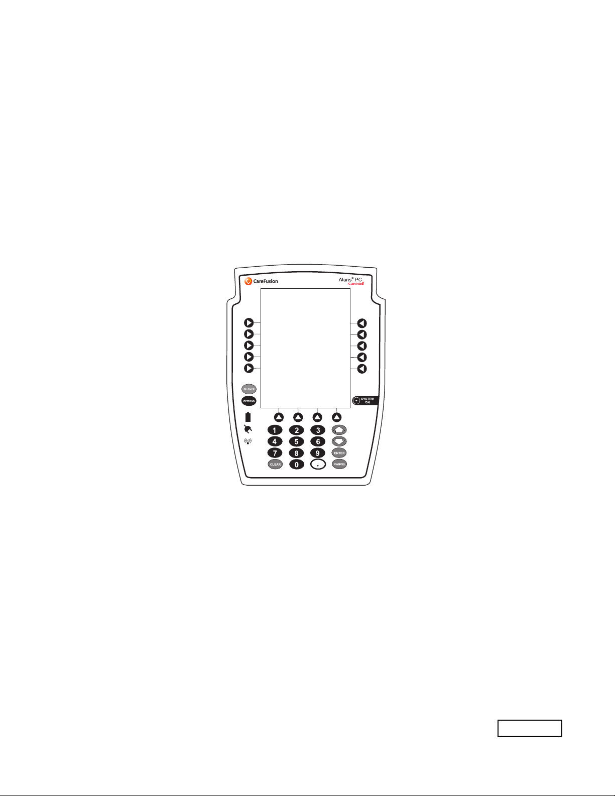
Operating Features, Controls, Indicators
Main Display
Soft Keys: When pressed,
allows selection of options or
infusion parameters appearing
on Main Display adjacent to
soft key.
Silence Key: When pressed
during an alarm, silences audio
for 2 minutes.
Options Key: When pressed,
allows access to available
System or Channel Options.
Soft Keys (see above)
Battery Indicator: When
illuminated, indicates
Alaris System is operating
on battery power.
ower Indicator: When
lluminated, indicates
laris System is connected
o an AC power source.
Wireless Network
Indicator: When illuminated,
indicates Alaris System is
connected to Alaris Systems
Manager. When blinking,
indicates data transfer.
IUI Connector, Left
(not visible)
Clear Key: When
pressed, clears current
selected parameter setting
to "0".
Module Release Latch:
When pressed, allows
module to be removed.
IUI Connector, Right
System On Key: When
pressed, changes Alaris System
from standby to operating mode.
Up Key: When pressed,
increases parameter with each
key press or scrolls up when
pressed and held.
Down Key: When pressed,
decreased parameter with each
key press or scrolls down when
pressed and held.
Enter Key: When pressed,
confirms current parameter entry.
Cancel Key: When pressed,
sequentially backs out of current
setup sequence.
Decimal Key: When pressed,
inserts a decimal point in numeric
data.
Numeric Keypad
PC Unit Section General Information
Alaris System User Manual – with v9.33 Model 8015 1-39
Page 52

Features and Displays (Continued)
Operating Features, Controls, Indicators (Continued)
Rear Panel - IEC 802.11 a/b/g/n Wireless
Network Card
IUI Connector, Right IUI Connector, Left
Power Cord Strap
Use this bolt to reorient
Pole Clamp 90° for
attachment to a bed rail
instead of a pole.
Primary Audio Speaker
Rear Cover
Wireless
Antenna/Network
Card
Connector Plug over RJ45
Communication Data Port.
Tamper Resist Switch
General Information PC Unit Section
1-40 Alaris System User Manual – with v9.33 Model 8015
Page 53

Features and Displays (Continued)
Operating Features, Controls, Indicators (Continued)
Rear Panel - Compact Flash b/g or a/b/g
Wireless Card
IUI Connector, Right IUI Connector, Left
Use this bolt to reorient
Pole Clamp 90° for
attachment to a bed rail
instead of a pole.
Primary Audio Speaker
Connector Plug over RJ45
Communication Data Port.
Power Cord Strap
Compact Flash Wireless Network
Card (see illustration below for
LED location)
Tamper Resist Switch
Wireless Network Card LED
Flashes green when
Alaris System is powered up.
PC Unit Section General Information
Alaris System User Manual – with v9.33 Model 8015 1-41
Page 54

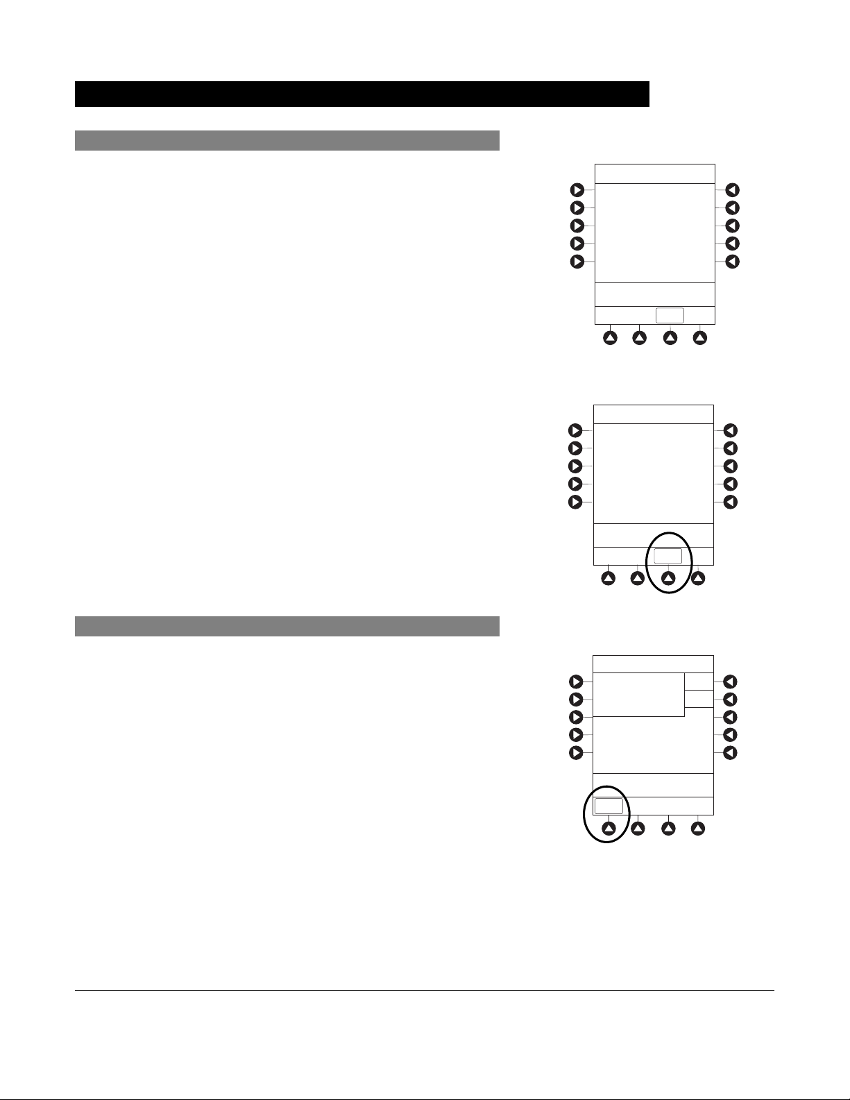
Features and Displays (Continued)
Displays
The displays illustrated throughout this document are for
illustration purposes only. The display content varies,
depending on configuration settings, hospital-defined Data
Set uploaded using the Guardrails Suite MX, and many other
variables.
A color versus monochrome display option is available when
creating a hospital-defined, best-practice Data Set. If no
Data Set is present or the Profiles feature is disabled, the
default is a color display. During normal operation, the title
and prompt bars are blue when a color display is enabled.
See "Troubleshooting and Maintenance," "Alarms, Errors,
Messages" for additional color categories.
Main Display
Title Bar
Module Status
• A solid letter display indicates
module is operating.
• An outlined letter display
indicates module is attached
and ready for use.
Soft Keys
Module Selected Indicator
"Inactive" Soft Key
Non-highlighted indicates a
non-selected soft key.
"Active" Soft Key
Highlighted indicates a
selected soft key.
Prompt Bar
Look here for user prompts.
Midtown Hospital
Adult ICU
VTBI = 250.0 mL
VOLUME
INFUSED
Infusion Setup
RATE
VTBI
>Press START
PAUSE
40 mL/h
_250 mL
AUDIO
ADJUST
SECOND-
ARY
START
General Information PC Unit Section
1-42 Alaris System User Manual – with v9.33 Model 8015
Page 55

System Configurable Settings
If the configuration settings need to be changed from the
Factory default settings, refer to the applicable Technical
Service Manual or contact CareFusion Technical Support,
for technical, troubleshooting, and preventive maintenance
information.
With the Profiles feature enabled, the settings are configured
independently for each Profile. A hospital-defined, bestpractice Data Set must be uploaded to enable the Profiles
feature. Date and Time is a system setting and is the same in
all Profiles.
Feature Default Setting Options
Alarm Audio Profile 1 Profile 1, 2, 3, or 4
Anesthesia Mode Disabled Enabled - Disabled
Battery Meter Disabled Enabled - Disabled
Clock Setup (Date and Time) Not Applicable Set date and time
Key Click Audio Enabled Enabled - Disabled
Max Patient Weight 500 kg 0.1 - 500 kg
Patient ID Entry Disabled Enabled - Disabled
PM Reminder
(Preventive Maintenance)
Profiles Disabled Enabled - Disabled
Tamper Resist Disabled Enabled - Disabled
Enabled Enabled - Disabled
PC Unit Section General Information
Alaris System User Manual – with v9.33 Model 8015 1-43
Page 56

Specifications and Symbols
Specifications
Battery Operation: Battery run time is a function of the number of modules attached and module
activity. With a new, fully charged battery, the system operates as follows before
a "BATTERY DISCHARGED" message occurs:
• 1 hour with four Pump modules infusion at 999 mL/h and one Auto-ID module
• 6 hours with one Pump module infusing at 25 mL/h
• 6 hours with one Pump module infusing at 25 mL/h
• 3 hours with four Pump modules infusing at 25 mL/h
• 3 hours with four Pump modules infusing at 25 mL/h and one Auto-ID module
• 4.5 hours with one active SpO2 module
• 6 hours with one Syringe module or PCA module infusing at 5 mL/h
• 3 hours with four Syringe modules, or one PCA module and three Syringe
modules, infusing at 5 mL/h
• 4 hours with one active EtCO2 module
Communication Data Port: RS-232 with an RJ45 connector.
Dimensions: 6.9" W x 8.8" H x 9" D (including pole clamp)
and one Auto-ID module
Electric Classification: Class 1, Internally Powered Equipment
Electronic Memory: The System configuration/data set is stored in compact flash memory along with
operating software.
The events and error logs, CQI, and historical reporting logs, and the system
alarm settings are stored in the on-board flash memory in the Alaris PC unit and
modules. This is nonvolatile memory and can be held indefinitely or until replaced
with new data. Logs and alarm settings are maintained even during a total loss of
power to the system. The date and time of system power down is captured in the
event log. The older log entries are purged as the log file reaches capacity. The
Alaris System's Tamper Resist Mode/Authorized User Modes restricts access to
making changes to logs or to the storage of logs.
Module-specific parameters are stored for 8 hours when system is turned
off. After 8 hours of continuous off-time, or if a module is detached, modulespecific trend data (if applicable) and module-specific operating parameters are
automatically purged. If a PCA, SpO2 or EtCO2
module is detached and replaced
with another PCA, SpO2, or EtCO2 module, its module-specific trend data is
purged.
Memory will not be lost due to a weak/discharged battery as data is stored on
flash memory as noted.
Compact flash memory: Stores application software, audio wave files, Data Set,
and hex files data for operating system software, all
needed to operate the Alaris System.
On-board flash memory: Contains software needed to initially turn on Alaris
System. Stores boot software application, and events,
errors and battery logs.
General Information PC Unit Section
1-44 Alaris System User Manual – with v9.33 Model 8015
Page 57

Specifications and Symbols (Continued)
Specifications (Continued)
Environmental Conditions:
Symbol Meaning Operating Storage/Transport
Atmospheric
Pressure
Relative Humidity
(Avoid prolonged
exposure to
relative humidity
>85%)
Temperature
Range
525 - 4560 mmHg
(700 - 6080 hPa)
20 - 90%
Noncondensing
41 - 104°F
(5 - 40°C)
375 - 760 mmHg
(500 - 1013 hPa)
5 - 85%
Noncondensing
-4 - 140°F
(-20 - 60°C)
Equipment Orientation: To ensure proper operation, Alaris System must remain in an upright position.
Fluid Ingress Protection: IPX1, Drip Proof
Mode of Operation: Continuous
Power Requirements: 100 - 240V ~, 50/60 Hz, 150 VA MAX
Shock Protection: Type CF, Defibrillator-Proof patient applied part
Weight: 7.2 lbs
PC Unit Section General Information
Alaris System User Manual – with v9.33 Model 8015 1-45
Page 58

Specifications and Symbols (Continued)
Symbols
See the product-specific section of this User Manual that applies to the attached module(s) for symbols
specific to that module.
Symbol Meaning
Alternating Current: Indicates device should be attached to alternating current source,
50/60 Hz only.
Warnings or Caution: Refer to accompanying documentation.
Canadian and U.S. Certification Mark: Products bearing this mark have been tested
C
US
and certified in accordance with applicable U.S. and Canadian electrical safety and
performance standards.
Communications connector for RS-232 attachment.
IPX1
MM-YYYY
Consult Instructions for Use.
Follow Instructions for Use
Type CF defibrillation-proof patient applied part.
Electrostatic discharge (ESD).
Fuse Replacement: Replace fuse only with same type and rating.
Protection against fluid ingress: Drip Proof.
IUI Connector: Inter-Unit Interface connector used to establish power and
communications between PC unit and attached modules.
Manufacturing Date: Number adjacent to symbol indicates month and year of
manufacture.
General Information PC Unit Section
1-46 Alaris System User Manual – with v9.33 Model 8015
Page 59

Specifications and Symbols (Continued)
Symbols (Continued)
Symbol Meaning
Manufacturer
Potential Equalization Conductor (if so equipped). Note: If integrity of PEC or Hospital
Earth System is in question, operate instrument using internal battery power.
Radio frequency (RF) transmission.
nly
O
EC REP
Caution: Federal (U.S.A) law restricts this device to sale by or on order of a physician.
Tamper Resist activate/deactivate switch.
Conformité Européenne (CE marking) notified body 0086: British Standards Institution.
Australian Communications Authority.
Federal Communications Commission.
Pursuant to Directive 2002/96/EC of the European Parliament and of the Council of
27 January 2003, on waste electrical and electronic equipment (WEEE).
Authorized representative in European Community.
PC Unit Section General Information
Alaris System User Manual – with v9.33 Model 8015 1-47
Page 60

THIS PAGE
INTENTIONALLY
LEFT BLANK
General Information PC Unit Section
1-48 Alaris System User Manual – with v9.33 Model 8015
Page 61

Figure , “Alaris Pump Module, Model 8100 Alaris Syringe Module, Model 8110,” on
™
page -5Alaris
Pump Module/Alaris™ Syringe Module
Alaris Pump Module, Model 8100
Alaris Syringe Module, Model 8110
L
A
M
R
A
FU
S
E
N
I
RATE (mL/h)
CHANNEL
SELECT
PAUSE
CHANNEL
OFF
RESTART
FU
S
N
E
I
S
T
A
M
N
R
A
L
S
T
A
N
D
B
Y
A
D
B
Y
RATE (mL/h)
CHANNEL
SELECT
PAUSE
CHANNEL
OFF
RESTART
Alaris System User Manual – with v9.33 Model 8015 Section 2
Page 62

THIS PAGE
INTENTIONALLY
LEFT BLANK
Page 63

Table of Contents
Getting Started
Introduction............................................................................................................................................. 2-1
Prepare Administration Set (Pump Module)........................................................................................... 2-3
Load................................................................................................................................................ 2-3
Remove .......................................................................................................................................... 2-6
Prime .............................................................................................................................................. 2-6
Prepare Syringe and Administration Set (Syringe Module).................................................................... 2-7
Load ....................................................................................................................................................... 2-11
Prime—Using Options Menu.................................................................................................................. 2-15
Prime—Manual....................................................................................................................................... 2-20
Programming
Introduction............................................................................................................................................. 2-23
Manual Programming with Guardrails Suite MX
Manual Programming—Primary Infusion ............................................................................................... 2-24
Continuous Infusion........................................................................................................................ 2-27
Bolus Dose ..................................................................................................................................... 2-33
Intermittent Infusion ........................................................................................................................ 2-40
Fluid Infusion .................................................................................................................................. 2-45
Manual Programming—Secondary Infusion (Pump Module) ................................................................. 2-51
Setup .............................................................................................................................................. 2-51
Infusion ........................................................................................................................................... 2-52
Stop Secondary and Return to Primary.......................................................................................... 2-57
Programming with Interoperability and Guardrails Suite MX
Programming with Interoperability—Initial Primary Infusion................................................................... 2-62
Continuous Infusion........................................................................................................................ 2-67
Fluid Infusion .................................................................................................................................. 2-69
Intermittent Infusion ........................................................................................................................ 2-70
Programming with Interoperability—Subsequent Primary Infusion (Pump Module) .............................. 2-72
Continuous Infusion........................................................................................................................ 2-74
Fluid Infusion .................................................................................................................................. 2-76
Intermittent Infusion ........................................................................................................................ 2-78
Programming with Interoperability—Secondary Infusion (Pump Module).............................................. 2-81
Infusion ........................................................................................................................................... 2-81
Stop Secondary and Return to Primary.......................................................................................... 2-86
Programming—NO Guardrails Suite MX Protection
Manual Programming—NO Guardrails Suite MX Protection.................................................................. 2-88
Basic Infusion without Drug Calculation ......................................................................................... 2-88
Promote Basic Infusion to Guardrails Software Protection Infusion ............................................... 2-89
Basic Infusion with Drug Calculation .............................................................................................. 2-89
Bolus Dose ..................................................................................................................................... 2-92
Secondary Infusion................................................................................................................................. 2-94
Infusion ........................................................................................................................................... 2-94
Stop Secondary and Return to Primary.......................................................................................... 2-95
Pump and Syringe Modules Section Table of Contents
Alaris System User Manual – with v9.33 Model 8015 2-iii
Page 64

General Programming
Pause, Change, Restart Infusion ........................................................................................................... 2-96
Pause and Restart Infusion ............................................................................................................ 2-96
Change Rate or VTBI During Infusion ............................................................................................ 2-97
Restore Infusion ............................................................................................................................. 2-97
View and Clear Volume Infused............................................................................................................. 2-98
Channel Labels ...................................................................................................................................... 2-99
Select.............................................................................................................................................. 2-99
Remove .......................................................................................................................................... 2-101
Anesthesia Mode.................................................................................................................................... 2-102
Delay Options......................................................................................................................................... 2-102
Delay Infusion................................................................................................................................. 2-103
Schedule a Callback....................................................................................................................... 2-106
Pause Infusion................................................................................................................................ 2-107
Multidose Mode...................................................................................................................................... 2-108
Volume/Duration Enabled............................................................................................................... 2-110
Volume/Duration Disabled.............................................................................................................. 2-111
Select Pressure Limit ............................................................................................................................. 2-113
Pump Module ................................................................................................................................. 2-113
Syringe Module............................................................................................................................... 2-114
General Setup and Operation
System Start-Up/Setup........................................................................................................................... 2-121
Set Up for Gravity Infusion (Pump Module).................................................................................... 2-121
Change Solution Container (Pump Module)................................................................................... 2-121
Change Syringe During Infusion (Syringe Module) ........................................................................ 2-122
General Information
Warnings and Cautions.......................................................................................................................... 2-125
General........................................................................................................................................... 2-125
Administration Sets......................................................................................................................... 2-128
Epidural Administration................................................................................................................... 2-132
Guardrails Suite MX ....................................................................................................................... 2-133
Administration Set/Syringe Information .................................................................................................. 2-133
SmartSiteTM Infusion Set (Pump Module)....................................................................................... 2-134
Safety Clamp Fitment (Pump Module) ........................................................................................... 2-135
Compatible Syringes (Syringe Module) .......................................................................................... 2-136
Features and Displays............................................................................................................................ 2-137
Features and Definitions................................................................................................................. 2-137
Operating Features, Controls, Indicators........................................................................................ 2-143
Displays .......................................................................................................................................... 2-146
Drug Calculation Definitions and Formulas ............................................................................................ 2-147
Configurable Settings............................................................................................................................. 2-148
Shared Infusion .............................................................................................................................. 2-149
Pump Module ................................................................................................................................. 2-150
Syringe Module............................................................................................................................... 2-151
Specifications ......................................................................................................................................... 2-152
Pump Module ................................................................................................................................. 2-152
Syringe Module............................................................................................................................... 2-155
Table of Contents Pump and Syringe Modules Section
2-iv Alaris System User Manual – with v9.33 Model 8015
Page 65

Symbols.................................................................................................................................................. 2-159
Trumpet and Start-Up Curves ................................................................................................................ 2-160
Pump Module ................................................................................................................................. 2-160
Syringe Module............................................................................................................................... 2-161
Graphs............................................................................................................................................ 2-162
Pump and Syringe Modules Section Table of Contents
Alaris System User Manual – with v9.33 Model 8015 2-v
Page 66

THIS PAGE
INTENTIONALLY
LEFT BLANK
Pump and Syringe Modules Section
2-vi Alaris System User Manual – with v9.33 Model 8015
Page 67

Introduction
This section of the User Manual provides Pump module (Model
8100) and Syringe module (Model 8110) instructions and
information. It is used in conjunction with:
• Alaris™ product administration set instructions
• Drug product labeling
• PC unit section of this User Manual
• AlarisTM Pump Module Set Compatibility Card
• AlarisTM Syringe Module Set Compatibility Card
• Pump Module Technical Service Manual
• Syringe Module Technical Service Manual
• System Maintenance software (and its instructions) for Alaris
System check-in, maintenance, and wireless configuration
Essential Performance
The Alaris infusion modules are designed to accurately deliver
the programmed amount of the medication or fluid over the
programmed time period. The Alaris infusion modules ensure
that an infusion is not being inadvertently delivered when the
user expects the system to be in a paused, stopped, or off
condition. The Alaris infusion modules employ measurement
systems to detect and alarm for conditions adverse to safe
administration of fluid. These include measurements of proper
infusion set loading (free flow detection), pressure (occlusion
detection), and air-in-line detection.
Getting Started
WARNING
Read all instructions, for both the
infusion modules and PC unit, before
using the Alaris System.
The EtC0
module will monitor and alarm when a patient
2
physiological condition is out of range.
The Sp0
module will monitor and alarm when a patient
2
physiological condition is out of range.
The Pump and Syringe modules are intended for facilities that
utilize infusion and/or syringe pumps for the delivery of fluids,
medications, blood, and blood products using continuous or
intermittent delivery through clinically acceptable routes of
administration; such as, intravenous (IV), intra-arterial (IA),
subcutaneous, epidural, enteral, or irrigation of fluid spaces.
The Pump and Syringe modules are indicated for use on
adults, pediatrics, and neonates. Up to four Pump and/or
Syringe modules can be connected to the Alaris System.
Pump and Syringe Modules Section Getting Started
Alaris System User Manual – with v9.33 Model 8015 2-1
Page 68

Introduction (Continued)
If a procedure/information applies to a specific module, the
following identifiers indicate the module it applies to.
FU
S
E
N
I
S
T
A
N
M
D
R
B
A
Y
L
A
RATE(mL/h)
CHANNEL
SELECT
Pump module:
Syringe module:
Administration Sets/Syringes: See "General Information" for
specific "Administration Set/Syringe Information.
Alarms and Alerts: See “Appendix A” "Troubleshooting and
Maintenance" for module-specific alarms and alerts.
PAUSE
CHANNEL
OFF
RESTART
FU
S
N
E
I
S
T
A
M
N
R
D
A
B
L
Y
A
RATE(mL/h)
CHANNEL
SELECT
PAUSE
CHANNEL
OFF
RESTART
Contraindications: None known.
Electromagnetic Environment: See "Appendix A" section of
this User Manual ("Regulations and Standards,"
"Compliance").
Getting Started Pump and Syringe Modules Section
2-2 Alaris System User Manual – with v9.33 Model 8015
Page 69

Prepare Administration Set (Pump Module)
FU
S
E
N
I
S
T
A
N
M
D
R
B
A
Y
L
A
RATE(mL/h)
CHANNEL
SELECT
PAUSE
CHANNEL
OFF
RESTART
For instructions on how to go from checking in a Pump module
to preparing it for an infusion setup, see "General Setup and
Operation."
Load
1. Ensure that the instrument is as close
FU
S
E
N
I
S
T
A
N
M
D
to the level of patient’s heart as
R
A
L
A
B
Y
possible - the patient’s heart should
be in line with
key.
CHANNEL SELECT
Align with Patient’s heart level
RATE(mL/h)
CHANNEL
SELECT
PAUSE
CHANNEL
OFF
RESTART
WARNING
• Administration Sets:
• Use only Alaris Pump
TM
module/GEMINI
Infusion
System administration sets.
The
use
of any other set can
cause improper instrument
operation, resulting in an
inaccurate fluid delivery or other
potential
compatible
please refer to the Alaris
hazard. For a list of
administration sets,
TM
Pump
Module Set Compatibility Card.
• Discard if packaging is not intact or
protector caps are unattached.
CAUTION
• Ensure that the device is as close
to level of patient’s heart as
possible. Patient’s heart level
should be in line with the
CHANNEL SELECT key.
• Use compatible components
which have the smallest internal
volume or "deadspace" to
minimize residual volumes
between the syringe and the
patient when administering
medications or fluids at low
infusion rates (e.g.,< 5 mL/h, and
especially flow rates < 0.5 mL/h).
This reduces the amount of time it
takes for fluid to reach the patient,
maintains delivery accuracy, and
reduces occlusion detection
times.
Pump and Syringe Modules Section Getting Started
Alaris System User Manual – with v9.33 Model 8015 2-3
Page 70

Prepare Administration Set (Pump Module) (Continued)
Load (Continued)
2. If a new set is being loaded, prime the set, see Prime on
page 2-6.
3. Open the Pump module door.
4. Load administration set, as follows:
a. Hold upper fitment above fitment recess and lower into
recess.
b. Ensure that tubing is not twisted.
FU
S
E
N
I
S
T
A
N
M
D
R
B
A
Y
L
A
RATE(mL/h)
CHANNEL
SELECT
PAUSE
CHANNEL
OFF
RESTART
CAUTION
• Avoid use of manifolds with ports
containing high pressure valves.
High pressure valves require
additional pressure (e.g., 50 - 200
mmHg) to open and allow fluid
flow. These high pressure valves
may cause a significant delay in
therapy followed by a sudden
bolus once the valve is opened,
particularly at low infusion rates
(e.g., < 5 mL/h, and especially
flow rates < 0.5 mL/h).
• Failure to follow proper
administration set loading
instructions might lead to an
instrument malfunction.
• Before operating the instrument,
verify that the administration set is
free from kinks and correctly
installed.
• Insert upper fitment before
installing safety clamp
fitment.
• When
reloading an
administration set, leave the
safety clamp
fitment in the
closed position (see “General
Information,” “Safety Clamp
Fitment”).
Getting Started Pump and Syringe Modules Section
2-4 Alaris System User Manual – with v9.33 Model 8015
Page 71

Prepare Administration Set (Pump Module) (Continued)
Load (Continued)
FU
S
E
N
I
S
T
A
N
M
D
R
B
A
Y
L
A
RATE(mL/h)
CHANNEL
SELECT
PAUSE
CHANNEL
OFF
RESTART
c. Press safety clamp fitment into recess below
mechanism.
d. Using a finger tip, firmly push tubing toward back of
Air-in-Line (AIL) Detector.
5. Close door and latch, as follows:
a. Close door and hold in a closed
position by grasping door and
instrument case with one hand.
b. Gently lower latch.
Safety clamp device is automatically
disengaged.
CAUTION
To reduce the potential for nuisance
AIL alarms, ensure that tubing is
fully inserted in the AIL Detector.
Safety Clamp Fitment
Push tubing toward
back of AIL Detector.
WARNING
• Do not touch the administration
set while closing the door. Failure
to follow this instruction can result
in infusion rate inaccuracy.
•To prevent a potential free-
flow condition, ensure that no
extraneous object (for example,
bedding, tubing, glove) is
enclosed or caught in the Pump
module door.
6. Open roller clamp.
7. Verify that no fluid is flowing through drip chamber.
Pump and Syringe Modules Section Getting Started
Alaris System User Manual – with v9.33 Model 8015 2-5
Page 72

Prepare Administration Set (Pump Module) (Continued)
Remove
1. Close roller clamp.
2. Open Pump module door.
Set’s safety clamp fitment automatically closes to prevent
accidental free-flow.
3. Remove set, as follows:
a. Gently pull tubing below Air-in-Line Detector forward
and out.
FU
S
E
N
I
S
T
A
N
M
D
R
B
A
Y
L
A
RATE(mL/h)
CHANNEL
SELECT
PAUSE
CHANNEL
OFF
RESTART
White Slide Clamp
(shown in closed position)
b. Lift upper fitment from upper fitment receptacle.
4. If set is being removed to begin a gravity flow:
a. Depress the blue ridged release tab on upper side of
safety clamp device.
b. Slide the white slide clamp into blue fitment (open
position).
c. Adjust the flow rate using set’s roller clamp.
Prime
1. Prepare primary solution container in accordance with
manufacturer’s User Manual.
2. Open administration set package, remove set, and close
roller clamp. (Refer to set’s User Manual.)
3. Insert administration set spike into prepared fluid
container, following accepted hospital/facility procedure,
and hang container 20 inches above Pump module.
4. Fill drip chamber to
⅔ full.
Getting Started Pump and Syringe Modules Section
2-6 Alaris System User Manual – with v9.33 Model 8015
Page 73

Prepare Administration Set (Pump Module) (Continued)
Prime (Continued)
5. If container requires venting, open vent cap on
administration set spike.
6. To prime tubing and clear air from injection sites and
tubing fitments, slowly open roller clamp.
7. When priming is complete, close roller clamp.
FU
S
E
N
I
S
T
A
N
M
D
R
B
A
Y
L
A
RATE(mL/h)
CHANNEL
SELECT
PAUSE
CHANNEL
OFF
RESTART
8. Verify no fluid flow.
Prepare Syringe and Administration Set (Syringe Module)
To decrease potential start-up delays, delivery inaccuracies,
and delayed generation of occlusion alarms, each time a new
syringe is loaded:
• Use smallest syringe size possible (for example, if infusing
2.3 mL of fluid, use a 3 mL syringe).
• Use compatible components which have the smallest
internal volume or "deadspace." For example:
◦ Tubing internal diameter: Smallbore or microbore tubing
is recommended when infusing at low rates
◦ Tubing length: Tubing length should be minimized, when
possible
◦ Filters: Internal volume (deadspace) of in-line filters
should be minimized
◦ Connection sites: The number of connection sites such
as stopcocks and y-sites should be limited, and high risk
or life-sustaining solutions should be connected as close
to the vascular access site as possible
FU
S
N
E
I
S
T
A
M
N
R
D
A
B
L
Y
A
RATE(mL/h)
CHANNEL
SELECT
PAUSE
CHANNEL
OFF
RESTART
Pump and Syringe Modules Section Getting Started
Alaris System User Manual – with v9.33 Model 8015 2-7
Page 74

Prepare Syringe and Administration Set (Syringe Module) (Continued)
WARNINGS
• Raising a syringe pump may result in a bolus of medication
or fluid due to changes in hydrostatic pressure. Lowering a
syringe pump while infusing may result in a delay in the
infusion (or possible under-infusion) due to the changes in
hydrostatic pressure.
• Ensure syringe sizes and models are compatible with the
Syringe module. Use of incompatible syringes can cause
improper pump operation resulting in inaccurate fluid
delivery, insufficient occlusion (blockage) sensing, and
other potential problems.
• Use the smallest compatible syringe size necessary to
deliver the fluid or medication; this is especially important
when infusing high risk or life-sustaining medications at low
infusion rates (for example, < 5 mL/h, and especially flow
rates < 0.5 mL/h). Using a larger syringe when infusing at
low rates can lead to inadequate syringe pump
performance including delivery inaccuracies, delay of
therapy, and delayed generation of occlusion alarms. This
is due to the increased friction and compliance of the
syringe stopper with larger syringes.
FU
S
N
E
I
S
T
A
M
N
R
D
A
B
L
Y
A
RATE(mL/h)
CHANNEL
SELECT
PAUSE
CHANNEL
OFF
RESTART
• Electronically prime the syringe pump system before
starting an infusion or after replacing a near-empty syringe
with a replacement syringe.
• Failure to use the PRIME SET WITH SYRINGE feature
after every syringe change can significantly delay the
infusion delivery start-up time and lead to delivery
inaccuracies.
Getting Started Pump and Syringe Modules Section
2-8 Alaris System User Manual – with v9.33 Model 8015
Page 75

Prepare Syringe and Administration Set (Syringe Module) (Continued)
•
CAUTION
• Use compatible components which have the smallest
internal volume or "deadspace" to minimize residual
volumes between the syringe and the patient when
administering medications or fluids at low infusion rates
(e.g.,< 5 mL/h, and especially flow rates < 0.5 mL/h). This
reduces the amount of time it takes for fluid to reach the
patient, maintains delivery accuracy, and reduces occlusion
detection times
• Ensure that the device is as close to level of patient ’s heart
as possible. Patient’s heart level should be in line with the
CHANNEL SELECT key.
FU
S
N
E
I
S
T
A
M
N
R
D
A
B
L
Y
A
RATE(mL/h)
CHANNEL
SELECT
PAUSE
CHANNEL
OFF
RESTART
• Use the
PRIME SET WITH SYRINGE channel option on the
Alaris Syringe module to speed up the engagement of the
module’s mechanical components and decrease the
syringe’s internal friction (see "Prime - Using Options
Menu").
• If using a pre-run infusion practice (to allow for medication
equilibration prior to connection to the patient), ensure that
the distal end of the administration set is level with or higher
than the device.
• Avoid use of manifolds with ports containing high pressure
valves. High pressure valves require additional pressure
(e.g., 50 - 200 mmHg) to open and allow fluid flow. These
high pressure valves may cause a significant delay in
therapy followed by a sudden bolus once the valve is
opened, particularly at low infusion rates (e.g., < 5 mL/h
and especially flow rates < 0.5mL/h).
These recommendations are especially important when
infusing high-risk or life-sustaining medications at low
infusion rates (for example, < 5 mL/h and especially at flow
rates < 0.5 mL/h).
Pump and Syringe Modules Section Getting Started
Alaris System User Manual – with v9.33 Model 8015 2-9
Page 76

Prepare Syringe and Administration Set (Syringe Module) (Continued)
For instructions on how to go from checking in a Syringe
module to preparing it for an infusion setup, including how to
change a syringe during infusion, see "General Setup and
Operation."
1. Prepare syringe (For a list of compatible syringes, refer to
Compatible Syringes (Syringe Module) on page 2-136 and
the Alaris
accordance with manufacturer’s User Manual.
2. Prepare administration set in accordance with
manufacturer’s User Manual.
3. Attach upper fitting of administration set to syringe tip.
NOTE:
For a list of compatible syringes, refer to Compatible Syringes
(Syringe Module) on page 2-136 and the AlarisTM Syringe
Module Set Compatibility Card. For a listing of administration
sets, refer to the AlarisTM Pump Module Set Compatibility Card.
TM
Syringe Module Set Compatibility Card) in
FU
S
N
E
I
S
T
A
M
N
R
D
A
B
L
Y
A
RATE(mL/h)
CHANNEL
SELECT
PAUSE
CHANNEL
OFF
RESTART
Getting Started Pump and Syringe Modules Section
2-10 Alaris System User Manual – with v9.33 Model 8015
Page 77
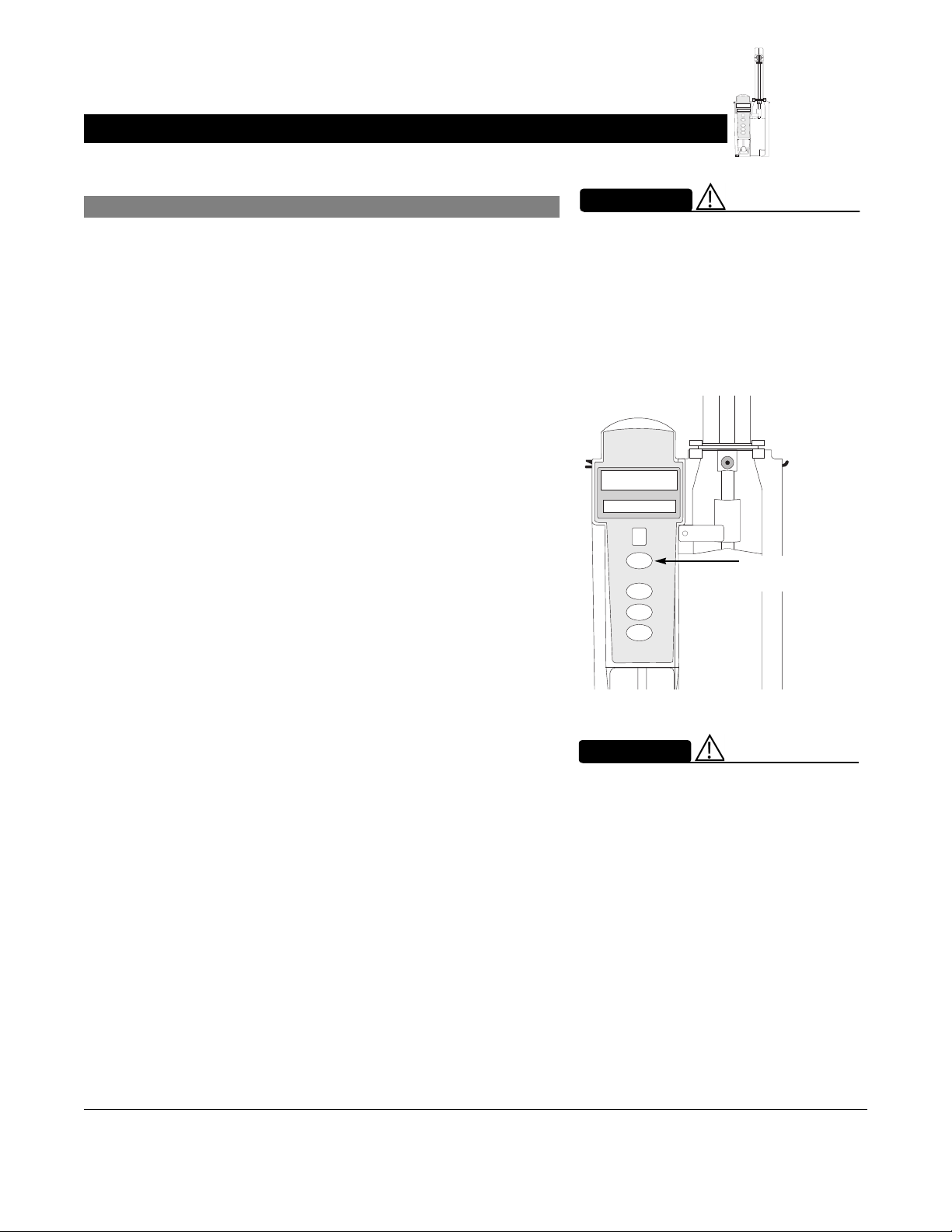
Prepare Syringe and Administration Set (Syringe Module) (Continued)
FU
S
N
E
I
S
T
A
M
N
R
D
A
B
L
Y
A
RATE(mL/h)
CHANNEL
SELECT
PAUSE
CHANNEL
OFF
RESTART
Load
4. Ensure that instrument is as close to level of patient’s heart
as possible—patient’s heart level should be in line with
CHANNEL SELECT key.
• Keep the Alaris System level with the patient’s heart to
maintain positive pressure.
• If using a pre-run infusion practice (to allow for
medication equilibration prior to connection to the
patient), ensure that the distal end of the administration
set is level with or higher than the device.
WARNING
Before loading or unloading the
syringe, always turn off fluid flow to
the patient, using the tubing clamp or
stopcock. Uncontrolled fluid flow
can occur when the administration
set is not clamped or turned off, and
can cause serious injury or death.
FU
S
N
E
I
S
T
A
M
N
R
A
L
A
RATE (mL/h)
CHANNEL
SELECT
PAUSE
CHANNEL
OFF
RESTART
D
B
Y
Align with Patient
heart level
WARNING
Raising a syringe pump may result in
a bolus of medication or fluid due to
changes in hydrostatic pressure.
Lowering a syringe pump while
infusing may result in a delay in the
infusion (or possible under-infusion)
due to the changes in hydrostatic
pressure.
Pump and Syringe Modules Section Getting Started
Alaris System User Manual – with v9.33 Model 8015 2-11
Page 78

Prepare Syringe and Administration Set (Syringe Module) (Continued)
Load (Continued)
.
5. Open syringe barrel clamp.
a. Pull syringe barrel clamp out and hold.
b. Rotate clamp to left (clockwise or counter clockwise)
until it clears syringe chamber.
c. Gently release clamp.
Syringe Barrel Clamp Open
6. Raise drive head to its fully extended position.
a. Twist gripper control clockwise and hold in position.
b. While holding gripper control in open position, raise
drive head to full extension.
c. Gently release gripper control.
Drive Head Fully Extended
Gripper Control/Drive
Head Release in Open
Position
Plunger Grippers Open
M
R
A
L
A
FU
S
N
E
I
RATE (mL/h)
CHANNEL
SELECT
PAUSE
FU
S
N
E
I
S
T
A
M
N
R
D
A
B
L
Y
A
RATE(mL/h)
CHANNEL
SELECT
PAUSE
CHANNEL
OFF
RESTART
S
T
A
N
D
B
Y
7. Insert syringe (from front of instrument) by sliding flat edge
of syringe barrel flange between barrel flange grippers.
FU
S
N
E
I
S
T
A
M
N
R
D
A
B
L
Y
A
oz
60
2
55
50
45
RATE(mL/h)
CHANNEL
SELECT
PAUSE
CHANNEL
RESTART
OFF
oz
60
2
55
50
45
1½
40
35
oz
30
1
25
20
15
½
10
5
WARNING
Before loading the syringe, check it
for damage or defects.
CAUTION
When initially loading the syringe,
allow for the volume of fluid
contained in the administration set
and retained in the syringe at the
end of an infusion, as this “dead
space” will not be infused.
Getting Started Pump and Syringe Modules Section
2-12 Alaris System User Manual – with v9.33 Model 8015
Page 79

40
Prepare Syringe and Administration Set (Syringe Module) (Continued)
Load (Continued)
FU
S
N
E
I
S
T
A
M
N
R
D
A
B
L
Y
A
RATE(mL/h)
CHANNEL
SELECT
PAUSE
CHANNEL
OFF
RESTART
8. Lock syringe in place.
a. Pull syringe barrel clamp out and hold.
b. Rotate clamp to right (clockwise or counter clockwise)
until it lines up with syringe.
c. Gently release clamp against syringe.
9. Lower drive head and lock plunger in place with plunger
grippers.
a. Twist gripper control clockwise and hold in position.
b. While holding gripper control in open position, gently
lower drive head until it makes contact with plunger
flange.
c. Gently release gripper control.
d. Ensure that plunger grippers lock and hold plunger in
place.
Gripper Control in
Closed Position
Drive Head Flush
with Plunger Flange
Plunger Grippers Closed
A
L
A
N
I
M
R
RATE(mL/h)
FU
S
E
S
T
A
N
D
B
Y
oz
60
2
55
50
45
1½
WARNING
Ensure that syringe barrel, flange,
and plunger are installed and
secured correctly. Failure to install
syringe correctly can result in
uncontrolled fluid flow to the patient,
and can cause serious injury or
death.
FU
S
E
N
I
S
T
A
M
N
R
D
A
B
L
Y
A
oz
60
2
55
RATE(mL/h)
CHANNEL
SELECT
PAUSE
50
45
1½
40
35
oz
30
1
25
20
Syringe Barrel Clamp Closed
CAUTION
•To avoid an occlusion when
loading a smaller size syringe,
use extra care to close off
administration set tubing and
gently lower drive head against
syringe plunger.
• For smaller syringes (such as;
3, or 5 mL), stabilize the syringe
1,
plunger with thumb and index
finger while carefully lowering
the drive head. Ensure that the
syringe plunger head makes
contact with the small black
sensor, located on the bottom of
the drive head (between the
plunger grippers).
Pump and Syringe Modules Section Getting Started
Alaris System User Manual – with v9.33 Model 8015 2-13
Page 80

Syringe Module
SELECT
Prepare Syringe and Administration Set (Syringe Module) (Continued)
Load (Continued)
FU
S
N
E
I
S
T
A
M
N
R
D
A
B
L
Y
A
RATE(mL/h)
CHANNEL
SELECT
PAUSE
CHANNEL
OFF
RESTART
10. Insert pressure sensing disc (if used), as follows:
a. Orient pressure sensing disc, as follows:
• fluid side up (patient side down)
• cavity forward (membrane toward instrument)
WARNING
When the pressure sensing disc
is not being used and an occlusion
occurs, there is a risk of infusing
pressurized buildup of infusates
upon correction of the occlusion. To
avoid an inadvertent bolus, relieve
the pressure before restarting the
infusion.
Slot in Pressure
Sensing Disc
Housing
Pressure
Sensing Disc
Fluid Side
Patient Side
b. Gently slide pressure sensing disc up into slot in
pressure sensing disc housing.
c. Apply firm upward pressure on pressure sensing disc
PAUSE
CHANNEL
RESTART
OFF
(not tubing) until disc snaps into place.
Pressure Sensing Disc
Getting Started Pump and Syringe Modules Section
2-14 Alaris System User Manual – with v9.33 Model 8015
Page 81

Prepare Syringe and Administration Set (Syringe Module) (Continued)
Load (Continued)
FU
S
N
E
I
S
T
A
M
N
R
D
A
B
L
Y
A
RATE(mL/h)
CHANNEL
SELECT
PAUSE
CHANNEL
OFF
RESTART
NOTES:
The gripper control is spring loaded. When twisted to the open
position and then released, it (and the plunger grippers) returns
to the closed position.
The following Syringe module features are available only with
extension sets fitted with a pressure sensing disc:
Auto Pressure
Back Off (upon occlusion)
Customized Pressure Alarm Settings (see “Occlusion
Pressure” feature definition)
Dynamic Pressure Display
Numeric Pressure Display
Fast Start
(See “General Information,” “Features and Displays” for
definitions.)
Prime—Using Options Menu
The Priming option can be enabled at the time the
Alaris System is configured for use. The Priming selection
(
PRIME soft key) is available only after the syringe and infusion
type have been selected, and prior to beginning an infusion.
If a pressure sensing disc is in use, it should be removed from
the instrument before priming. See the applicable procedure
(as follows) depending on whether or not a pressure sensing
disc is used.
WARNING
Electronically prime the syringe
pump system before starting an
infusion or after replacing a near
empty syringe with a replacement
syringe. Using the syringe pump's
prime feature engages the
mechanical components of the pump
and decreases the syringe's friction
and compliance to minimize startup
delays and delivery inaccuracies,
especially at low infusion rates.
Failure to use the prime feature on
the syringe pump after every syringe
change and/or tubing change can
significantly delay the infusion
delivery startup time and lead to
delivery inaccuracies.
WARNING
When priming:
• Ensure that administration set is
not connected to patient.
• Ensure that air is expelled from
line prior to beginning infusion
(unexpelled air in line could have
serious consequences).
Failure to prime correctly can delay
infusion delivery and cause the total
volume to be infused to read higher
than the actual total delivered to the
patient.
CAUTION
During priming, the pressure limit
alarms are temporarily increased to
their maximum level.
Pump and Syringe Modules Section Getting Started
Alaris System User Manual – with v9.33 Model 8015 2-15
Page 82

Prepare Syringe and Administration Set (Syringe Module) (Continued)
Prime—Using Options Menu (Continued)
FU
S
N
E
I
S
T
A
M
N
R
D
A
B
L
Y
A
RATE(mL/h)
CHANNEL
SELECT
PAUSE
CHANNEL
OFF
RESTART
Administration Set
With Pressure
Sensing Disc
1. Ensure that administration set is not connected to patient.
2. If installed, remove pressure sensing disc from instrument.
Using a finger, apply firm downward pressure on pressure
sensing disc (not tubing) until disc snaps loose from slot in
pressure sensing disc housing.
3. Press
OPTIONS key.
CAUTION
The pressure sensing disc, if left
installed during priming, can trap air
that might not be totally expelled.
To ensure that entrapped air is
eliminated, it is recommended
that the pressure sensing disc be
removed prior to priming and the
membrane gently massaged with a
finger while priming. After priming
is completed, reinstall the pressure
sensing disc.
SILENCE
OPTIONS
SYSTEM
ON
1
2
3
4
5
6
ENTER
9
CANCEL
4. Press Prime Set with Syringe soft key.
7
8
CLEAR
0
Channel Options 1 of 2
A
Guardrails Drugs
Guardrails IV Fluids
Multidose
Pressure Limit - 550 mmHg
Prime Set with Syringe
>Select an Option or EXIT
EXIT
PAGE
DOWN
Getting Started Pump and Syringe Modules Section
2-16 Alaris System User Manual – with v9.33 Model 8015
Page 83

Prepare Syringe and Administration Set (Syringe Module) (Continued)
Prime—Using Options Menu (Continued)
FU
S
N
E
I
S
T
A
M
N
R
D
A
B
L
Y
A
RATE(mL/h)
CHANNEL
SELECT
PAUSE
CHANNEL
OFF
RESTART
Administration Set
With Pressure Sensing
Disc (Continued)
If pressure sensing disc was not removed prior to pressing
Prime Set with Syringe soft key, a pressure sensing disc
removal prompt is displayed.
5. Invert pressure sensing disc so that patient side is up.
6. Hold pressure sensing disc between two fingers.
A
AA
It is recommended that the
Pressure Sensing Disc be
removed during priming.
Press CONFIRM and
continue priming.
>Press CONFIRM
Patient Side
CONFIRM
20
15
½
10
5
7. Press and hold
PRIME soft key.
A
Prime Set with Syringe
CAUTION: Do
not prime with
disposable set
connected to
patient!
Prime Volume
0 mL
>Press and Hold PRIME
EXIT
PRIME
Pump and Syringe Modules Section Getting Started
Alaris System User Manual – with v9.33 Model 8015 2-17
Page 84

Syringe Module
Prepare Syringe and Administration Set (Syringe Module) (Continued)
Prime—Using Options Menu (Continued)
FU
S
N
E
I
S
T
A
M
N
R
D
A
B
L
Y
A
RATE(mL/h)
CHANNEL
SELECT
PAUSE
CHANNEL
OFF
RESTART
Administration Set
With Pressure Sensing
Disc (Continued)
8. Gently massage pressure sensing disc to ensure that all
air is expelled. The disc must remain inverted only until the
air is expelled. Continue to gently massage disc
throughout priming to ensure that it does not become
under- or over- filled.
9. Continue to prime until fluid flows and priming is complete.
Fluid is delivered during priming only while
key is pressed. Each press of
PRIME soft key delivers up
PRIME soft
to 2 mL of priming fluid at the maximum rate of the
selected syringe per continuous press. To deliver
additional amounts, press
PRIME soft key again.(See Rate
Restriction by Syringe Size: on page 2-157)
10. When priming is complete, release pressure sensing disc
PRIME soft key.
and
Volume used during priming is displayed but not added to
VTBI or VI.
A
Prime Set with Syringe
CAUTION: Do
not prime with
disposable set
connected to
patient!
Prime Volume
2mL
>Press and Hold PRIME
EXIT
PRIME
11. Reinstall pressure sensing disc, as follows:
a. Orient pressure sensing disc, as follows:
• fluid side up (patient side down)
• cavity forward (membrane toward instrument)
b. Gently slide pressure sensing disc up into slot in
pressure sensing disc housing.
Getting Started Pump and Syringe Modules Section
2-18 Alaris System User Manual – with v9.33 Model 8015
Slot in Pressure
Sensing Disc
Housing
Pressure
Sensing Disc
Patient Side
Fluid Side
Page 85

Prepare Syringe and Administration Set (Syringe Module) (Continued)
Prime—Using Options Menu (Continued)
FU
S
N
E
I
S
T
A
M
N
R
D
A
B
L
Y
A
RATE(mL/h)
CHANNEL
SELECT
PAUSE
CHANNEL
OFF
RESTART
Administration Set
With Pressure Sensing
Disc (Continued)
c. Apply firm upward pressure on pressure sensing disc
(not tubing) until disc snaps into place.
12. To return to main screen, press
If
EXIT soft key is pressed before pressure sensing disc is
EXIT soft key.
reinstalled, a prompt to reinstall pressure sensing disc is
displayed.
Pressure Sensing Disc
A
AA
Re-install Pressure Sensing
Disc.
>Press CONFIRM
CONFIRM
Administration Set
With No Pressure
Sensing Disc
1. Press
2. Press Prime Set with Syringe soft key.
Pump and Syringe Modules Section Getting Started
Alaris System User Manual – with v9.33 Model 8015 2-19
OPTIONS key.
Channel Options 1 of 2
A
Guardrails Drugs
Guardrails IV Fluids
Multidose
Pressure Limit - 550 mmHg
Prime Set with Syringe
>Select an Option or EXIT
EXIT
PAGE
DOWN
Page 86

Prepare Syringe and Administration Set (Syringe Module) (Continued)
Prime—Using Options Menu (Continued)
3. Press and hold PRIME soft key until fluid flows and priming
is complete.
FU
S
N
E
I
S
T
A
M
N
R
D
A
B
L
Y
A
RATE(mL/h)
CHANNEL
SELECT
PAUSE
CHANNEL
OFF
RESTART
Fluid is delivered during priming only while
key is pressed. Each press of
PRIME soft key delivers up
PRIME soft
to 2 mL of priming fluid per continuous press. To deliver
additional amounts, press
4. Release
PRIME soft key.
PRIME soft key again.
Volume used during priming is displayed but not added to
VTBI or VI.
5. To return to main screen, press
EXIT soft key.
Prime—Manual
Use the following procedures to manually prime the
administration set.
WARNING
When priming:
• Ensure that administration set is
not connected to patient.
• Ensure that air is expelled from
line prior to beginning infusion
(unexpelled air in line could have
serious consequences).
Failure to prime correctly can delay
infusion delivery and cause the total
volume to be infused to read higher
than the actual total delivered to the
patient.
Getting Started Pump and Syringe Modules Section
2-20 Alaris System User Manual – with v9.33 Model 8015
Page 87

Prepare Syringe and Administration Set (Syringe Module) (Continued)
Prime—Manual (Continued)
FU
S
N
E
I
S
T
A
M
N
R
D
A
B
L
Y
A
RATE(mL/h)
CHANNEL
SELECT
PAUSE
CHANNEL
OFF
RESTART
Administration Set
With Pressure
Sensing Disc
1. Ensure that administration set is not connected to patient.
2. If installed, remove pressure sensing disc from instrument.
Using a finger, apply firm downward pressure on pressure
sensing disc (not tubing) until disc snaps loose from slot in
pressure sensing disc housing.
3. Invert pressure sensing disc so that patient side is up.
4. Hold pressure sensing disc between 2 fingers.
CAUTION
The pressure sensing disc, if left
installed during priming, can trap air
that might not be totally expelled.
To ensure that entrapped air is
eliminated, it is recommended
that the pressure sensing disc be
removed prior to priming and the
membrane gently massaged with a
finger while priming. After priming
is completed, reinstall the pressure
sensing disc.
20
15
½
10
5
5. Slowly prime set while gently massaging pressure sensing
Patient Side
disc to ensure that all air is expelled. The disc must remain
inverted only until the air is expelled. Continue to gently
massage disc throughout priming to ensure that it does
not become under- or over-filled.
6. When priming is complete (no air exists), close set clamp.
NOTE:
When manually priming (per hospital/facility protocol) and an
administration set having a pressure sensing disc is in use,
depress the disc between 2 fingers while priming and prime
uphill (distal end of pressure sensing disc/tubing pointing
upward).
Pump and Syringe Modules Section Getting Started
Alaris System User Manual – with v9.33 Model 8015 2-21
Page 88

Prepare Syringe and Administration Set (Syringe Module) (Continued)
Prime—Manual (Continued)
FU
S
N
E
I
S
T
A
M
N
R
D
A
B
L
Y
A
RATE(mL/h)
CHANNEL
SELECT
PAUSE
CHANNEL
OFF
RESTART
Administration Set
With No Pressure
Sensing Disc
1. Prime per hospital protocol.
2. When priming is complete (no air exists), close set clamp.
Eliminate Mechanical Slack
To eliminate mechanical slack or free play, and minimize
start-up delays and delivery inaccuracies, especially when
infusing at low flow rates, it is recommended that the
instrument be primed per the following procedure.
1. Load syringe (see "Load" procedure). If a pressure
sensing disc is being used, do not install disc until priming
is complete.
2. Select syringe and infusion type (see "Programming"
chapter).
3. Open administration set clamp.
4. Prime, as follows, using Priming option (see "Prime -Using
Options Menu"):
a. Follow applicable procedure (based on whether or
not pressure sensing disc is installed) through step to
press and hold
PRIME soft key.
b. Prime until fluid drips from end of tubing.
c. Complete procedure (installing pressure sensing disc,
if applicable, and exiting options menu).
Getting Started Pump and Syringe Modules Section
2-22 Alaris System User Manual – with v9.33 Model 8015
Page 89

Introduction
The Alaris System can be programmed with Guardrails Suite
MX Protection or with no Guardrails Suite MX protection:
• Guardrails Suite MX Protection
• Manual Programming (see page 2-24)
• Programming with Interoperability (see page 2-58)
• Auto-ID (Refer to Section "Auto-ID")
• No Guardrails Suite MX Protection
• Manual Programming Basic Infusion
• Manual Programming Basic Infusion with Drug
Calculation
References throughout this procedure to specific drugs and
drug doses are for illustration purposes only. Refer to specific
drug product labeling for information concerning appropriate
administration techniques and dosages.
Programming
See "General Information," "Features and Displays" and the
PC unit section of this User Manual for information about:
• Displays
• Operating Features, Controls, Indicators
The majority of user interface programming is identical for both
the Pump module and Syringe module. When referring to both
modules, the term "infusion modules" is used. The modules are
referred to singularly as the Pump module and the Syringe
module.
Pump and Syringe Modules Section Programming
Alaris System User Manual – with v9.33 Model 8015 2-23
Page 90

Manual Programming with Guardrails Suite MX
Manual Programming—Primary Infusion
The following procedures are to be used only when the drug
to be infused is listed in the Drug Library. To access the Drug
Library, a hospital-defined best-practice Data Set must be
transferred to the Alaris System and the Profile feature must be
enabled.
1. Perform following steps (see PC unit section of this
manual, "General Setup and Operation," "Start-Up"):
a. Power on system.
b. Choose Yes or No to New Patient?
c. Confirm current Profile or select a new Profile.
d. Enter patient identifier, if required.
FU
S
N
E
I
S
T
A
M
N
R
D
A
B
L
Y
A
FU
S
E
N
I
S
T
A
N
M
D
R
B
A
Y
L
A
RATE(mL/h)
RATE(mL/h)
CHANNEL
SELECT
CHANNEL
SELECT
PAUSE
PAUSE
CHANNEL
OFF
CHANNEL
OFF
RESTART
RESTART
2. Prepare and load syringe/administration set (see "Getting
Started").
3. Prime (see "Getting Started").
Manual Programming with Guardrails Suite MX Pump and Syringe Modules Section
2-24 Alaris System User Manual – with v9.33 Model 8015
Page 91

Manual Programming—Primary Infusion (Continued)
4. Press CHANNEL SELECT key.
FU
S
N
E
I
S
T
A
M
N
R
D
A
B
L
Y
A
FU
S
E
N
I
S
T
A
N
M
D
R
B
A
Y
L
A
RATE(mL/h)
RATE(mL/h)
CHANNEL
SELECT
CHANNEL
SELECT
PAUSE
PAUSE
CHANNEL
OFF
CHANNEL
OFF
RESTART
RESTART
5. Syringe module: Select syringe type and size, as
6.
follows; otherwise, proceed to step
syringe is loaded correctly, but not recognized, check
FU
S
N
E
I
S
T
A
M
N
R
D
A
B
L
Y
A
RATE(mL/h)
for the following:
CHANNEL
SELECT
PAUSE
CHANNEL
OFF
RESTART
If the installed
a. If a label is between the syringe barrel and the barrel
clamp, make sure that the label does not erroneously
enlarge the barrel size of the syringe.
b. If a needle-free valve or other component is added to
the syringe, ensure that it is no larger than the diameter
of the syringe barrel.
NOTE:
Thick labeling or adding a component to the syringe that is larger
than the diameter of the syringe may prevent the device from
correctly recognizing the installed syringe. If the issue continues
despite the above troubleshooting, send the device to your
facility’s biomedical engineering department for servicing.
Pump Module
Syringe Module
WARNING
Ensure that the displayed syringe
manufacturer and syringe size
FU
S
N
E
I
S
T
A
M
N
R
D
A
B
L
Y
correctly identify the installed
syringe. Mismatches might
cause an under-infusion or
A
RATE(mL/h)
CHANNEL
SELECT
PAUSE
CHANNEL
OFF
RESTART
over-infusion to the patient that
could result in serious injury and/or
death. For a list of compatible
syringes, refer to Compatible
Syringes (Syringe Module) on page
2-136 and the Alaris
Module Set Compatibility Card.
TM
Syringe
Pump and Syringe Modules Section Manual Programming with Guardrails Suite MX
Alaris System User Manual – with v9.33 Model 8015 2-25
Page 92
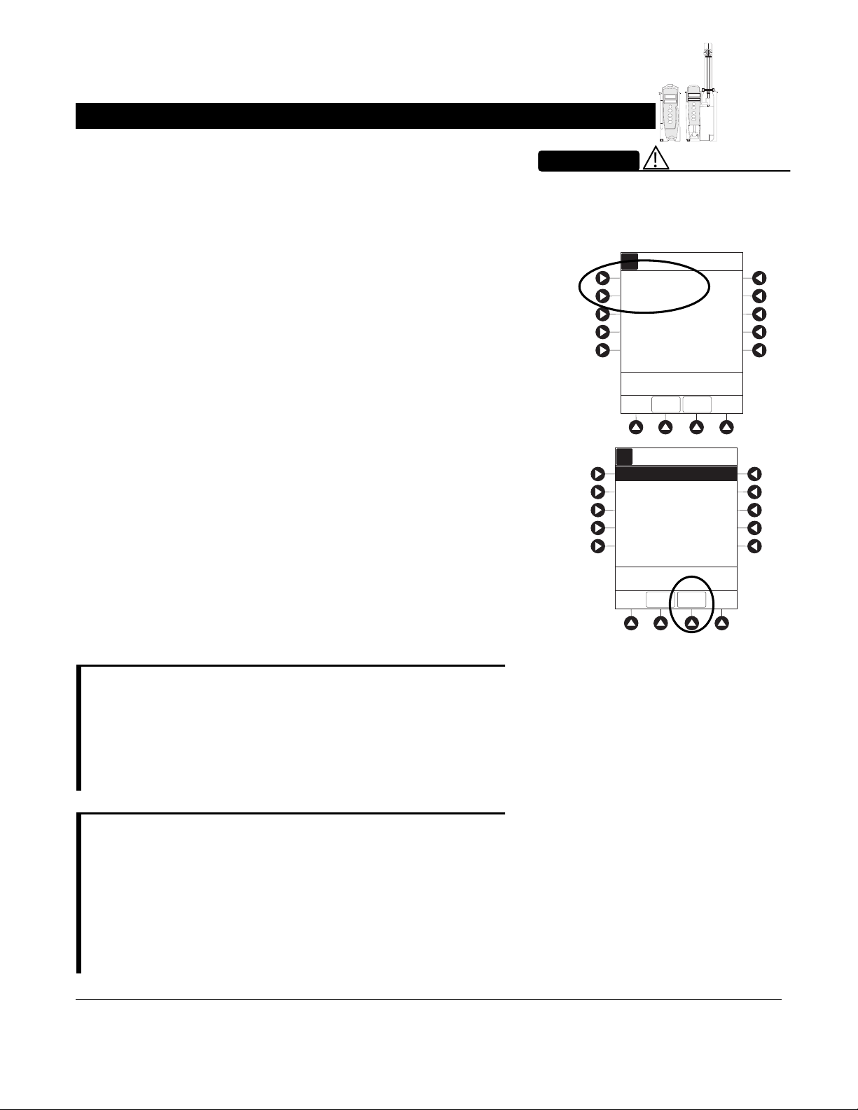
Manual Programming—Primary Infusion (Continued)
c. Press soft key next to installed syringe type and size. If
a default syringe list has been enabled and correct
syringe cannot be found, press the
key to select from a list of all compatible syringes.
d. To accept, press
CONFIRM soft key.
ALL SYRINGES soft
FU
S
N
E
I
S
T
A
M
N
R
D
A
B
L
Y
A
FU
S
E
N
I
S
T
A
N
M
D
R
B
A
Y
L
A
RATE(mL/h)
RATE(mL/h)
CHANNEL
SELECT
CHANNEL
SELECT
PAUSE
PAUSE
CHANNEL
OFF
CHANNEL
OFF
RESTART
RESTART
WARNING
Selecting an incorrect syringe may
cause an under infusion or over
infusion to the patient.
Syringe Selection
A
A
BD 30 mL
Monoject 30 mL
>Select Syringe Size
ALL
CONFIRM
SYRINGES
Syringe Selection
A
A
BD 30 mL
Monoject 30 mL
6. Start applicable infusion, as described in following
procedures:
Continuous Infusion
Bolus Dose
Intermittent Infusion
Fluid Infusion
NOTE:
At the start of a Syringe module infusion program, the system
prompts to select and confirm the syringe type and size.
The system automatically detects the syringe size, and lists
syringe types and sizes that most closely match the installed
syringe. If the syringe is not recognized, Syringe not
recognized is displayed.
NOTE:
It is possible to program an infusion with a rate that is
displayed with two decimal places (one-hundredth of a mL per
hour) on the PC unit for the Pump module. However, due to
space limitations on the Pump module rate display, the rate
is displayed to the nearest one-tenth of a mL per hour on the
Pump module. This value is only used for display purposes
and the Pump module is actually infusing at the more precise
rate noted on the PC unit.
>Confirm Syringe Size
ALL
CONFIRM
SYRINGES
Manual Programming with Guardrails Suite MX Pump and Syringe Modules Section
2-26 Alaris System User Manual – with v9.33 Model 8015
Page 93

Manual Programming—Primary Infusion (Continued)
Continuous Infusion
When using a drug listed in the Drug Library, the drug
parameters are automatically calculated, based on:
• drug selected
• weight entry (if required)
• rate or dose entry
•
VTBI entry (Syringe module—if other than All)
FU
S
N
E
I
S
T
A
M
N
R
D
A
B
L
Y
A
FU
S
E
N
I
S
T
A
N
M
D
R
B
A
Y
L
A
RATE(mL/h)
RATE(mL/h)
CHANNEL
SELECT
CHANNEL
SELECT
PAUSE
PAUSE
CHANNEL
OFF
CHANNEL
OFF
RESTART
RESTART
1. Press Guardrails Drugs soft key.
2. Press soft key next to desired drug.
• To view additional drugs/concentrations, press a soft
key next to a letter group to navigate through alphabet,
and/or
PAGE UP and PAGE DOWN soft keys.
Infusion Menu
A
Guardrails Drugs
Guardrails IV Fluids
Basic infusion
>Select an Option or EXIT
RESTORE
EXIT
Guardrails Drugs
A
A
Adult ICU
Alteplase
AMIODArone
DOBUTamine
DOPamine
Heparin
A-E
F-J
K-O
P-T
U-Z
>Select Drug
DRUG
CALC
PAGE
DOWN
EXIT
• If applicable, an optional hospital-defined therapy or
clinical indication for delivery of this infusion could
appear—as in illustrated example, which reflects use
of Alteplase. Different limits can be defined for same
Guardrails Drugs
A
A
Adult ICU
Alteplase
MI
Stroke
drug with different therapeutic indications.
Therapy indication appears on drug or
confirmation screen. Once drug or
confirmed, therapy indication appears in title bar.
Pump and Syringe Modules Section Manual Programming with Guardrails Suite MX
Alaris System User Manual – with v9.33 Model 8015 2-27
IV fluid
IV fluid has been
>Select Therapy Type
DRUG
EXIT
LIBRARY
Page 94

Manual Programming—Primary Infusion (Continued)
Continuous Infusion (Continued)
FU
S
N
E
I
S
T
A
M
N
R
D
A
B
L
Y
A
FU
S
E
N
I
S
T
A
N
M
D
R
B
A
Y
L
A
RATE(mL/h)
RATE(mL/h)
CHANNEL
SELECT
CHANNEL
SELECT
PAUSE
PAUSE
CHANNEL
OFF
CHANNEL
OFF
RESTART
RESTART
• If applicable, a weight-based or non weight-based
option for delivery of this infusion could appear (as in
illustrated example, which reflects use of Heparin).
• If applicable, multiple concentration listings for delivery
of this infusion could appear (as in illustrated example,
which reflects use of Dopamine).
3. To continue programming, press Yes soft key.
®
Guardrails Drugs
A
A
Adult ICU
Heparin
Non-Weight based dosing
Weight based dosing
>Select Dose Unit Type
DRUG
EXIT
LIBRARY
Guardrails Drugs
A
A
Adult ICU
DOPamine
400mg/250mL
800mg/250mL
>Select Concentration
DRUG
EXIT
LIBRARY
Bolus Dose units appear if Bolus Dose is enabled.
OR
To change selection, press No soft key.
Manual Programming with Guardrails Suite MX Pump and Syringe Modules Section
2-28 Alaris System User Manual – with v9.33 Model 8015
Page 95

Manual Programming—Primary Infusion (Continued)
Continuous Infusion (Continued)
FU
S
N
E
I
S
T
A
M
N
R
D
A
B
L
Y
A
FU
S
E
N
I
S
T
A
N
M
D
R
B
A
Y
L
A
RATE(mL/h)
RATE(mL/h)
CHANNEL
SELECT
CHANNEL
SELECT
PAUSE
PAUSE
CHANNEL
OFF
CHANNEL
OFF
RESTART
RESTART
• If YES was selected and facility has defined a Clinical
Advisory for that drug, a message appears. To indicate
information has been noted and continue
programming, press
CONFIRM soft key.
• If Yes was selected to continue programming, drug
amount and diluent volume (if defined in Drug Library)
are automatically entered for selected drug.
Alteplase
A
Stroke
Clinical Advisory:
This dosing is for Acute
Ischemic STROKE
>Press CONFIRM
CONFIRM
Alteplase
A
Stroke
DRUG
AMOUNT
100 mg
DILUENT
VOLUME
100 mL
PATIENT
WEIGHT
Used
TIME
hour
UNITS
DOSING
mg/kg/h
UNITS
[Conc]: 1 mg/mL
>Press NEXT to Confirm
DRUG
NEXT
LIBRARY
• If selected drug had "_ _ / _ _ mL" concentration, drug
amount and diluent volume need to be entered.
• If selected drug is not weight-based, Not Used is
displayed in
PATIENT WEIGHT field.
• If hospital/facility practice guidelines identify selected
drug as weight-based, prompt for a patient weight in
kilograms appears (as in illustrated example, which
reflects use of Alteplase).
4. Verify correct parameters and press NEXT soft key to
confirm.
Alteplase
A
Stroke
DRUG
AMOUNT
100 mg
DILUENT
VOLUME
100 mL
PATIENT
____kg
WEIGHT
TIME
hour
UNITS
DOSING
mg/kg/h
UNITS
[Conc]: 1 mg/mL
>Enter Patient Weight
DRUG
LIBRARY
Pump and Syringe Modules Section Manual Programming with Guardrails Suite MX
Alaris System User Manual – with v9.33 Model 8015 2-29
Page 96

Manual Programming—Primary Infusion (Continued)
Continuous Infusion (Continued)
5. An optional hospital-defined and editable starting value for
Continuous Infusion dose might already be entered.
OR
FU
S
N
E
I
S
T
A
M
N
R
D
A
B
L
Y
A
FU
S
E
N
I
S
T
A
N
M
D
R
B
A
Y
L
A
RATE(mL/h)
RATE(mL/h)
CHANNEL
SELECT
CHANNEL
SELECT
PAUSE
PAUSE
CHANNEL
OFF
CHANNEL
OFF
RESTART
RESTART
To make a rate or dose entry, press applicable soft key,
RATE or DOSE, and use numeric data entry keys (other
value is calculated and displayed).
6. To enter volume to be infused, press
VTBI soft key and
enter value.
• Pump module:
FU
S
E
N
I
S
T
A
N
M
D
R
B
A
Y
L
A
RATE(mL/h)
◦ When
CHANNEL
SELECT
PAUSE
CHANNEL
OFF
RESTART
decimal places (one-hundredth of a mL).
VTBI is less than 10 mL, entry can be to two
◦ In Drug Calculation mode, system infuses at
calculated rate rounded to nearest one-hundredth
of a mL per hour (as displayed on the programming
screen on the PC unit). The rate shown in Rate
Display on the Pump module is rounded to nearest
one-tenth of a mL per hour.
OR
Alteplase
A
AA
Stroke
CONTINUOUS INFUSION
RATE
___mL/h
VTBI
____mL
DOSE
_____mg/kg/h
[Conc]: 1 mg/mL
>Select Rate or Dose
SETUP
BOLUS
Alteplase
A
AA
Stroke
CONTINUOUS INFUSION
RATE
56.7 mL/h
VTBI
____
mL
DOSE
_ 0.81 mg/kg/h
[Conc]: 1 mg/mL
>Select VTBI
BOLUS
SETUP
BOLUS soft key appears only if Bolus Dose is enabled
•
within selected Profile, drug is bolusable, and a VTBI is
entered.
Manual Programming with Guardrails Suite MX Pump and Syringe Modules Section
2-30 Alaris System User Manual – with v9.33 Model 8015
Page 97

Manual Programming—Primary Infusion (Continued)
Continuous Infusion (Continued)
FU
S
N
E
I
S
T
A
M
N
R
D
A
B
L
Y
A
FU
S
E
N
I
S
T
A
N
M
D
R
B
A
Y
L
A
RATE(mL/h)
RATE(mL/h)
CHANNEL
SELECT
CHANNEL
SELECT
PAUSE
PAUSE
CHANNEL
OFF
CHANNEL
OFF
RESTART
RESTART
• Syringe module:
◦ If ALL Mode is enabled for syringe configuration in
FU
S
N
E
I
S
T
A
M
N
R
D
A
B
L
Y
A
RATE(mL/h)
CHANNEL
SELECT
PAUSE
CHANNEL
OFF
RESTART
Data Set,
estimated available volume in syringe is displayed.
OR
ALL is displayed in VTBI field and
If ALL Mode is disabled for syringe configuration in
Data Set, estimated available volume in syringe is
displayed when
VTBI soft key is pressed.
◦ To enter or change a numeric VTBI value, press
VTBI soft key and enter value.
◦ To deliver entire contents of syringe: Keep an
VTBI value, or press ALL soft key to change a
numeric
VTBI value to ALL.
ALL
Alteplase
A
AA
Stroke
CONTINUOUS INFUSION
RATE
VTBI
DOSE
56.7 mL/h
ALL
_ 0.81 mg/kg/h
Available:
(55.5 mL)
[Conc]: 1 mg/mL
>Select VTBI
START
BOLUS
SETUP
PAUSE
7. Verify correct parameters and press
START soft key.
• For a Continuous Infusion, the drug name and dose
will scroll on the module Message Display
Alteplase
AA
A
Stroke
CONTINUOUS INFUSION
RATE
56.7 mL/h
VTBI
100
mL
DOSE
0.81 mg/kg/h
[Conc]: 1 mg/mL
>Press START
PAUSE
SETUP
BOLUS
START
Pump and Syringe Modules Section Manual Programming with Guardrails Suite MX
Alaris System User Manual – with v9.33 Model 8015 2-31
Page 98

Manual Programming—Primary Infusion (Continued)
Continuous Infusion (Continued)
FU
S
N
E
I
S
T
A
M
N
R
D
A
B
L
Y
A
FU
S
E
N
I
S
T
A
N
M
D
R
B
A
Y
L
A
RATE(mL/h)
RATE(mL/h)
CHANNEL
SELECT
CHANNEL
SELECT
PAUSE
PAUSE
CHANNEL
OFF
CHANNEL
OFF
RESTART
RESTART
• If the programmed continuous dose infusion is outside
the Soft Limit for that care area, an audio alert sounds
and a visual prompt appears before programming can
continue. If Yes soft key is pressed, programming
continues; if No soft key is pressed, infusion needs to
be reprogrammed.
• If the programmed continuous dose infusion is outside
the Hard Limit for that care area, an audio alert sounds
and a visual prompt appears before programming can
continue. Infusion needs to be reprogrammed.
• If a dose outside of the Soft Limits has been entered
and verified as correct, Message Display also shows
either "LLL" for a low dose or "
" for a high dose.
Alteplase
A
Stroke
Dose exceeds
Guardrail limit of
0.81 mg/kg/h.
Proceed?
>Press Yes or No
Alteplase
A
Stroke
Dose exceeds
Reprogram
Guardrails hard
limit of 0.82 mg/kg/h.
>Press REPROGRAM
Yes
No
• If a Soft Limit is overridden, G icon is displayed. When
G soft key is pressed, all applicable out-of-range limits
are listed.
Midtown Hospital
Adult ICU
VTBI = 250 mL
A
VOLUME
INFUSED
AUDIO
ADJUST
G
Manual Programming with Guardrails Suite MX Pump and Syringe Modules Section
2-32 Alaris System User Manual – with v9.33 Model 8015
Page 99

Manual Programming—Primary Infusion (Continued)
Continuous Infusion (Continued)
8. Syringe module:
• Unclamp tubing and attach administration set to
FU
S
N
E
I
S
T
A
M
N
R
D
A
B
L
Y
A
RATE(mL/h)
CHANNEL
SELECT
PAUSE
CHANNEL
OFF
RESTART
NOTES:
The facility can choose to pre-populate standard drug
Patient weight can be edited during a Continuous Infusion.
Once a patient weight is entered and an infusion is started for
patient.
• Unclamping tubing and starting infusion before
attaching administration set to patient minimizes
any potential bolus that can be released from
pressure built up in set due to normal syringe
loading and priming.
concentrations, or leave a custom concentration (_ _ / _ _ mL)
and allow the clinician to enter the desired concentration.
any module, the patient weight is automatically entered for any
additional weight-based calculation. The patient weight
remains an editable field, therefore patient weight can be
adjusted for any module. Changing the patient weight on one
module does not affect the patient weight on any other module.
FU
S
N
E
I
S
T
A
M
N
R
D
A
B
L
Y
A
FU
S
E
N
I
S
T
A
N
M
D
R
B
A
Y
L
A
RATE(mL/h)
RATE(mL/h)
CHANNEL
SELECT
CHANNEL
SELECT
PAUSE
PAUSE
CHANNEL
OFF
CHANNEL
OFF
RESTART
RESTART
NOTE:
It is possible to program an infusion with a rate that is
displayed with two decimal places (one-hundredth of a mL per
hour) on the PC unit for the Pump module. However, due to
space limitations on the Pump module rate display, the rate
is displayed to the nearest one-tenth of a mL per hour on the
Pump module. This value is only used for display purposes
and the Pump module is actually infusing at the more precise
rate noted on the PC unit.
Bolus Dose
A Bolus Dose can be programmed at the beginning of, or
during, a continuous infusion. The drug being programmed
must be a bolusable drug selected from the Drug Library or a
non-library drug, as described in the following
procedures.
1. Set up infusion as described in "Continuous Infusion"
procedure, but do not start infusion.
Pump and Syringe Modules Section Manual Programming with Guardrails Suite MX
Alaris System User Manual – with v9.33 Model 8015 2-33
Page 100

Manual Programming—Primary Infusion (Continued)
FU
S
N
E
I
S
T
A
M
N
R
D
A
B
L
Y
A
FU
S
E
N
I
S
T
A
N
M
D
R
B
A
Y
L
A
RATE(mL/h)
RATE(mL/h)
CHANNEL
SELECT
CHANNEL
SELECT
PAUSE
PAUSE
CHANNEL
OFF
CHANNEL
OFF
RESTART
RESTART
Bolus Dose (Continued)
2. Press BOLUS soft key.
• If the programmed continuous dose infusion is outside
the Soft Limit for that care area, an audio alert sounds
and a visual prompt appears before programming can
continue. If Yes soft key is pressed, programming
continues; if No soft key is pressed, infusion needs to
be reprogrammed.
• If the programmed continuous dose infusion is outside
the Hard Limit for that care area, an audio alert sounds
and a visual prompt appears before programming can
continue. The infusion needs to be reprogrammed.
3. An optional hospital-defined and editable starting value
for Bolus Dose and/or bolus rate duration might already be
entered.
OR
To enter Bolus Dose, use numeric data entry keys.
• After a Bolus Dose and weight (if used) are entered,
bolus VTBI and concentration [conc] alternate in Main
Display.
Alteplase
AA
A
Stroke
CONTINUOUS INFUSION
RATE
56.7 mL/h
VTBI
100
mL
DOSE
0.81 mg/kg/h
[Conc]: 1 mg/mL
>Press START
PAUSE
A
AA
Alteplase
Stroke
SETUP
BOLUS
START
BOLUS DOSE
DOSE
____unit/kg
PATIENT
WEIGHT
DURATION
[Conc]: 1 mg/mL
>Enter Bolus Dose
CONT-
SETUP
INUOUS
• If no weight has previously been programmed in
system and Bolus Dose is weight-based, weight entry
is empty.
• If the programmed continuous dose is weight-based,
programmed weight is displayed.
• If Bolus Dose is not weight-based, Not Used is
displayed in
PATIENT WEIGHT field.
• A Bolus Dose can be either weight based or non
weight-based independent of whether the Continuous
Infusion is weight based or non weight-based.
4. Enter or change patient weight (if used), use applicable
following procedure, depending on whether or not
continuous dose is weight-based.
Manual Programming with Guardrails Suite MX Pump and Syringe Modules Section
2-34 Alaris System User Manual – with v9.33 Model 8015
 Loading...