

Page 1
8400STº
&
8400ST%
VOLUME
SERVICE
NOTE:
This
to
The
information
the
8400ST®°i
8400ST®
alsoapplies
is
located
name
is
referred
to
in
the
VENTILATOR
MANUAL
to
the
8400ST%;,
back
throughout
of
the
manual
Specific
the
contents
information
under
Addendums.
of
this
manual.
pertaining
only
©
1995
Bird
Products
Corporation
EE
aa
Bird
1100
(619)
(800/
©
Products
Corporation
Bird
Center
778-7200 M TLX:
328-4139 m FAX:
Drive,
Palm
Springs,
9103805605
(619)
778-7269
CA
92262
Page 2

Page 3
Bird
Products
Corporation
MANUAL
REVISION
8400ST
Service
/8400STi
Manual
Date
March
1998
Revision
pee
Rev.
Pages
D
Service
Manual
本
March
1898
Rev.
D
Page 4

Page 5
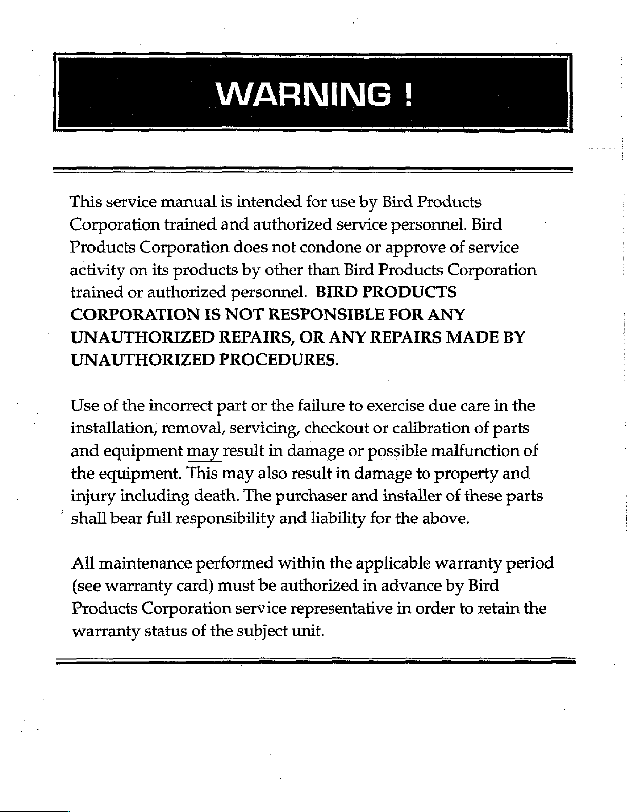
This
_
Corporation
Products
activity
trained
CORPORATION
UNAUTHORIZED
UNAUTHORIZED
service
Corporation
on
or
WARNING
manual
trained
its
products
authorized
is
and
IS
NOT
REPAIRS,
PROCEDURES.
intended
authorized
does
personnel.
not
by
other
RESPONSIBLE
for
condone
than
OR
use
service
Bird
BIRD
ANY
!
by
Bird
or
approve
Products
PRODUCTS
REPAIRS
Products
personnel.
FOR
Bird
of
service
Corporation
ANY
MADE
BY
Use
installation,
and
the
injury
shall
All
Products
warranty
of
the
equipment
equipment.
including
bear
maintenance
(see
warranty
incorrect
removal,
full
responsibility
card)
Corporation
status
part
servicing,
may
This
of
result
may
death.
performed
must
the
or
the
in
damage
also
The
be
service
subject
result
purchaser
and
within
authorized
representative
unit.
failure
checkout
liability
to
or
in
damage
and
the
applicable
exercise
or
calibration
possible
to
installer
for
the
above.
in
advance
in
order
due
care
malfunction
property
of
warranty
by
to
in
of
parts
and
these
Bird
parts
period
retain
the
of
the
Page 6

Page 7
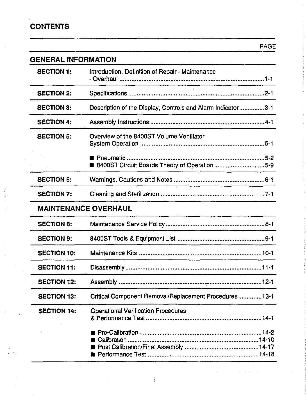
CONTENTS
-
GENERAL
SECTION
INFORMATION
1:
Introduction,
-
Overhaul
Definition
.ee
of
Repair - Maintenance
PAGE
'
1-1
SECTION
SECTION
SECTION
SECTION
SECTION
SECTION
MAINTENANCE
SECTION
SECTION
2:
3:
4:
5:
6:
7:
8:
9:
SpecificationS
Description
Assembly
Overview
System
M
PNEUMALIC
E
8400ST
Warnings,
Cleaning
OVERHAUL
Maintenance
8400ST
of
the
Display,
Instructions
of
the
8400ST
OperatiOn
....ononoocononcnonnnonoranonnroncnanaconconoconcanocraronon
Circuit
Cauiions
and
Boards
and
Sterilization
Service
Tools & Equipment
Controls
nr
Volume
Theory
NoteS
..........
Policy
List
ーー
昌和
and
Alarm
2-1
Indicator...............
3-1
4-1
Ventilator
ee
nora
onareorancoronons
of
Operation.............................
irene
rire
rire
receiver
ee
rene
nine
eeeeeneno
아아아
once
5-1
5-2
5-9
6-1
7-1
8-1
9-1
SECTION
SECTION
SECTION
SECTION
SECTION
10:
11:
12:
13:
14:
NES
Disassembly
Assembly
Critical
μμ
Component
Operational
&
Performance
画
Pre-CalbratiOn
B
Calibration
m
Post
Calibration/Final
E
Pertormance
IM
inserer
Removal/Replacement
Verification
TeSt
Procedures
issssseisnsnesnesnse
μϱ””ϱϱϱϱἛϱἛϱρρυ---
sise
Assembly
κ
μμ
μμ
esse
neee
aeeereeemeeremerenesenn
ke
ste v snes
steen
renen
Procedures..............
sarao
esser
sr
10-1
11-1
12-1
13-1
14-1
sense
Page 8
INDEX
SECTION
SECTION
SECTION
SECTION
SECTION
SECTION
SECTION
15:
16:
17:
18:
19:
20:
21:
Troubleshootind
m
Clinica!
m
Electronic
Schemalics・
DrawindS
AS
APPend
m
Explanation
Service
Non-Recoverable
Warranty
ϱ.ϱϱΓϱΓϱϱϱίμυ-
of
Bulletins
.......--cccsececetecsscessecesesssecccasesesesseresstseetareesaetesorsnsssseeessess
PAGE
ito
ee
rroccrnicroniono
A
15-1
16-1
17-1
18-1
Abbreviations
"sise
"Ventinop"Codes..............................-0004.......
19-1
20-1
21-1
O
1997
Contact
Dealer
_
Customer
Bird
Products
ORDERING
your
Bird
or
Bird
Products Corporation
Service
1100
Paim
(760)
(800)
Fax:
Corporation
INFORMATION
Products
Department
Bird
Center
Springs,
778-7200
328-4139
(760)
778-7274
Corporation
directly:
Drive
CA
92262
or
TECHNICAL
Contact
Bird
Technical
Paim
Products
Service
1100
Bird
Springs,
(760)
778-7200
BIRD
(800)
[(800)
INFORMATION
Corporation
Department
Center
CA 92262
directly:
Drive
or
HELPLINE
934-BIRD
934-2473]
Page 9
SECTION
Introduction
1
8400ST / 8400STi
Volume
Ventilator
Service
Manual
Page 10

Page 11
SECTION
1
INTRODUCTION
The
8400ST
Manual
theories
bleshooting,
instructions
technician
lator.
The
Service
for
use
that
is, a person
8400ST
authorized
ter.
Any
dures
should
that
be
Corporation
specific
theory
of
Operating
or
Sections 2 through 7 of
Service
oughly
familiar
Maintenance
service
INGS,
given
CAUTIONS,
particular
‘Sections 8 through
the
details
replacement
the
8400ST
structured
problem
replacing
manual
repair
on
of,
the
printed
however,
provided
complete
subassemblies
by
factory
Volume
contains
of
operation,
replacement,
to
assist a qualified
in
the
Manual
by
an
authorized
that
service
repairs,
exceed
referred
operating
operation,
Instruction
personnel
on
to a
that
does
for
complete
to
technical
seminar
by
Bird’s
Technical
with
procedures
this
equipment.
attention.
related
of
defective
ventilator.
around
defective
defective
not
example,
circuit
give
can
trained
pneumatic
maintenance
adjustments,
the
to
instructions
should
the
and
17
to
the
cover
schematic
the
information.
technical
Ventilator
Service
and
calibration,
and
maintenance
service
of
is
specifically
service
has
attended
conducted
Service
Training
or
scope
the
Service
of
Bird
this
Products
Center.
and
refer
to
the
8400ST
Manual,
P/N
this
manual.
become
Operating
before
The
NOTES
of
this
manual
the
diagnoses
subassemblies
This
manual
concept
of
subassembly
subassembly.
diagnoses
component
board
subassemblies;
information
service
be
technician
replaced
personnel.
electronic
trou-
the
venti-
intended
person;
a
or
Cen-
proce-
manual
For
clinical
L1141,
thor-
and
attempting
WARN-
should
isolating
Defective
in
be
cover
and
of
is
a
and
The
and
failures
is
the
field
Only
factory
attempt
ventilator.
are
diagnosis
based
Bird's
on
subassembly
training
on
how
maintenance
The
maintenance
ventilator
nance
includes
through
follows:
Every
Every
Every
15,000
1000
3000
5000
hours:
The 15,000
any
factory
important,
done
using
nents
tion.
in
considered
trained
however,
only
provided
addition,
complete
Performance
performed
this
manual,
All
repair
15,000
facility
available
in
and
hour
where
to
technicians.
trained
personnel
and
repair
service
fault
analysis
level
and
also
to
perform
of
the
ventilator.
schedule
preventative
the
first
15,000
hours:
examine
replace
necessary.
hours:
verify
calibration.
hours:
replace
filter
COMPLETE
OVERHAUL
hour
overhaul
service
that
the
maintenance
by
Bird
Products Corpora-
no
overhaul
until
Verification
accordance
maintenance,
overhaul,
proper
qualified,
can
service
trained
should
of a 8400ST
training
and
classes
repair
include
the
15,000
for a 8400ST
mainte-
hours
inlet
as
transducer
bacteria
in
patient
may
be
done
technician.
the
overhaul
compo-
should
an
Operational
test
has
been
with
Section
including
be
done
equipment
service
at
the
detailed
hour
as
filter;
circuit.
by
It
is
be
be
14
of
the
at
any
is
Page 12

Page 13
SECTION
2
Specifications
8400ST / 8400STi
Volume
Ventilator
Service
Manual
Page 14

Page 15
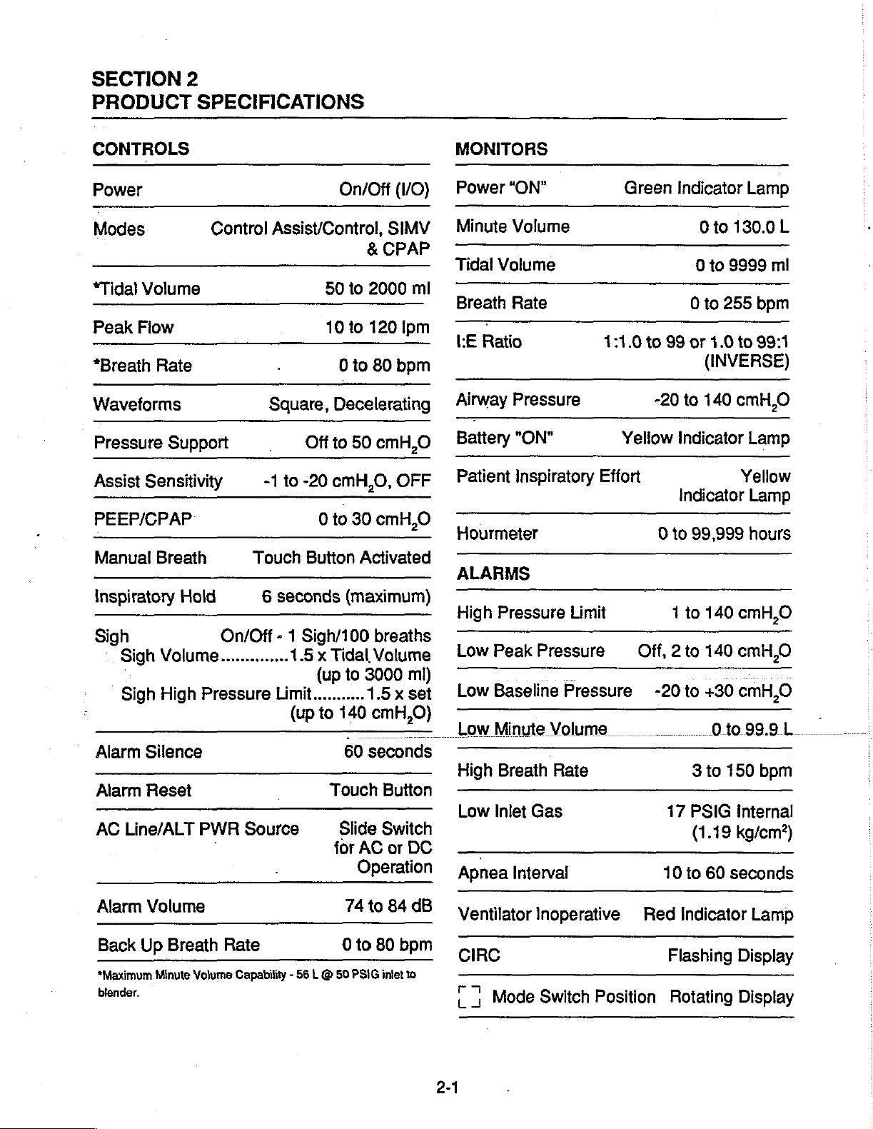
SECTION
PRODUCT
2
SPECIFICATIONS
CONTROLS
Power
Modes
*Tidal
Peak
*Breath
Volume
Flow
Rate
Waveforms
Pressure
Assist
Support
Sensitivity
PEEP/CPAP
Manual
Inspiratory
Sigh
Alarm
Alarm
AC
Alarm
Back
“Maximum
blender.
Breath
Hold
Sigh
Volume..............
Sigh
High
Silence
Reset
Line/ALT
Volume
Up
Breath
Minute
Volume
Control
Assist/Control,
Square,
-1
Touch
6
On/Off
Pressure
PWR
]
Rate
- 1
Limit...........
Source
Capability - 56 L @
50
10
Decelerating
Off
to
to
-20
cmH,O,
0
to
Button
seconds
Sigh/100
1.5x
Tidal
(up
(up
to
Touch
for
On/Off
(VO)
SIMV
&
CPAP
to
2000
to
120
Ipm
0
to
80
bpm
50
cmH,O
OFF
30
cmH,O
Activated
(maximum)
breaths
Volume
to
3000
1.5x
140
cmH,O)
-
60
seconds
Button
Slide
Switch
AC
or
Operation
74
to
84
0
to
80
bpm
50
PSIG
intet
ml
mi)
set
DC
dB
to
MONITORS
Power
Minute
-
Tidal
Breath
“ON”
Volume
Volume
Rate
ーー
LE Ratio
Airway
Battery
Patient
Pressure
"ON"
Inspiratory
Hourmeter
ALARMS
.
High
Pressure
Low
Peak
Low
Baseline
Low
Minute
High
Breath
Low
Inlet
Apnea
Interval
Ventilator
CIRC
|;
Mode
1:1.0
Effort
Limit
Pressure
-
Pressure
Volume
Rate
Gas
Inoperative
Switch
Position
Green
to
99
-20
Yellow
0
Off,
-20
17
10
Red
Flashing
Rotating
Indicator
0
to
130.0
0
to
9999
0
to
255
or
1.0
to
(INVERSE)
to
140
cmH,0
Indicator
Yellow
Indicator
to
99,999
1
to
140
cmH,O
2 to
140
cmH,O
to
+30
cmH,O
01099.9L
Sto
150
PSIG
(1.19
to
Internal
kg/cm?)
60
seconds
Indicator
Display
Display
Lamp
L
mi
bpm
99:1
Lamp
Lamp
hours
7
bpm
Lamp
2-1
Page 16
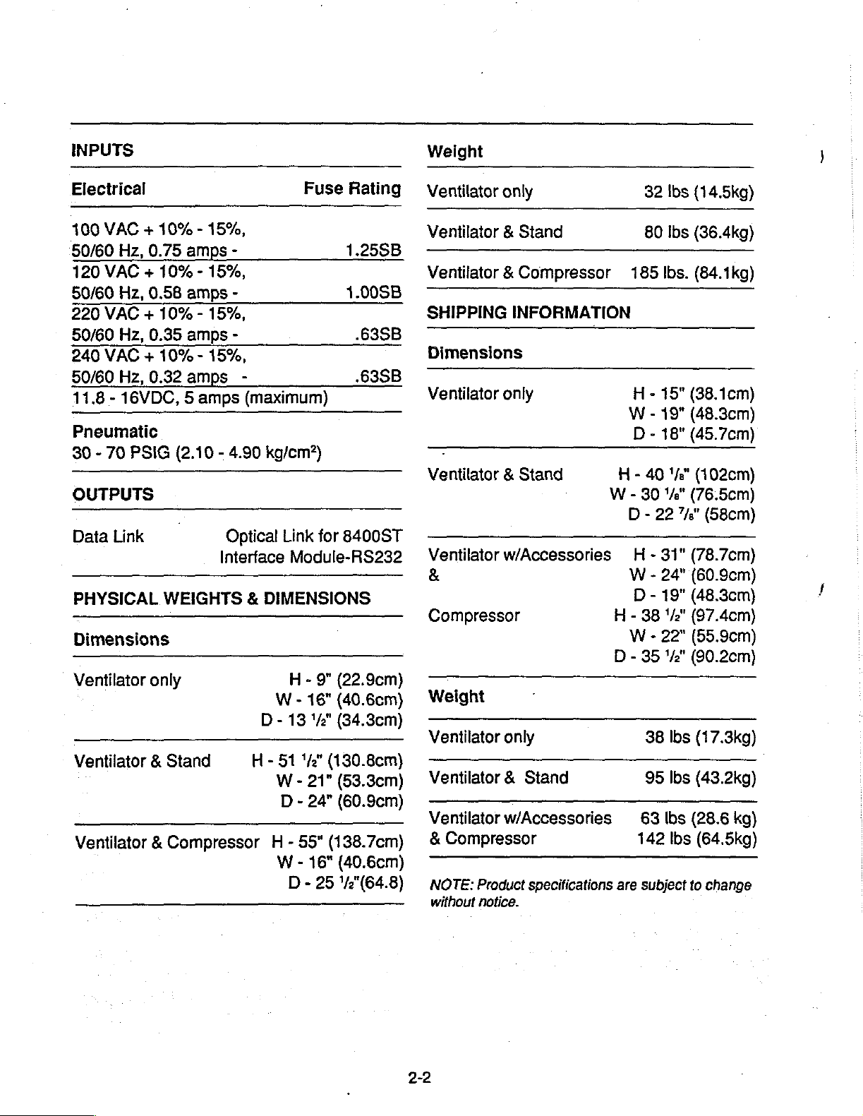
INPUTS
Electrical
100
VAC + 10% - 15%,
§0/60
120
50/60
220
50/60
240
50/60
11.8 - 16VDC, 5 amps
Hz,
0.75
amps
VAC + 10% - 15%,
Hz,
0.58
amps
VAC + 10% - 15%,
Hz,
0.35
amps
VAC + 10% - 15%,
Hz,
0.32
amps
Pneumatic
30 - 70
OUTPUTS
Data
PSIG
Link
(2.10 - 4.90
Optical
Interface
PHYSICAL
WEIGHTS & DIMENSIONS
Dimensions
Ventilator
only
Ventilator & Stand
Ventilator & Compressor
-
-
-
-
(maximum)
kg/cm?)
Link
Module-RS232
H - 9"
W - 16"
D-
13
H - 51
W - 21”
D - 24"
Н - 55"
W - 16"
D - 25
Fuse
Rating
1.25SB
1.00SB
.63SB
.63SB
for
8400ST
(22.9cm)
(40.6cm)
1/2"
(34.3cm)
1/2"
(130.8cm)
(53.3cm)
(60.9cm)
(138.7ст}
(40.6cm)
'/2"(64.8)
Weight
Ventilator
Ventilator & Stand
Ventilator & Compressor
SHIPPING
Dimensions
Ventilator
Ventilator & Stand
Ventilator
&
Compressor
Weight
Ventilator
Ventilator & Stand
Ventilator
&
Compressor
NOTE:
without
only
INFORMATION
only
w/Accessories
only
w/Accessories
Product
notice.
specifications
32
80
185
H - 15"
W - 19"
D - 18"
H-40'/"
W - 30
D - 22
-
W - 24"
D - 19"
H - 38
W - 22"
D - 35
38
95
63
142
are
subject
Ibs
(14.5kg)
Ibs
(36.4kg)
Ibs.
(84.1kg)
(38.1cm)
(48.3cm)
(45.7cm)
(102cm)
‘/e"
(76.5cm)
7%"
(58cm)
31"
(78.7ст)
(60.9cm)
(48.3cm)
‘/2"
(97.4cm)
(55.9cm)
"42"
(90.2cm)
lbs
(17.3kg)
Ibs
(43.2kg)
lbs
(28.6
lbs
(64.5kg)
to
change
kg)
Page 17
SECTION
3
Description
and
of
Alarm
the
Display,
Controls
Indicator
8400ST / 8400STi
Volume
Ventilator
Service
Manual
Page 18

Page 19
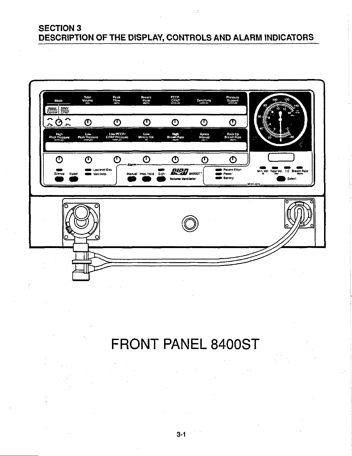
SECTION
DESCRIPTION
Assist | SIMV
Control | CPAP
3
OF
THE
DISPLAY,
CONTROLS
AND
ALARM
INDICATORS
FRONT
PANEL
8400ST
3-1
Page 20
DESCRIPTION
E
CONTROLS
OF
THE
DISPLAY,
CONTROLS
AND
ALARM
INDICATORS
Control | CPAP
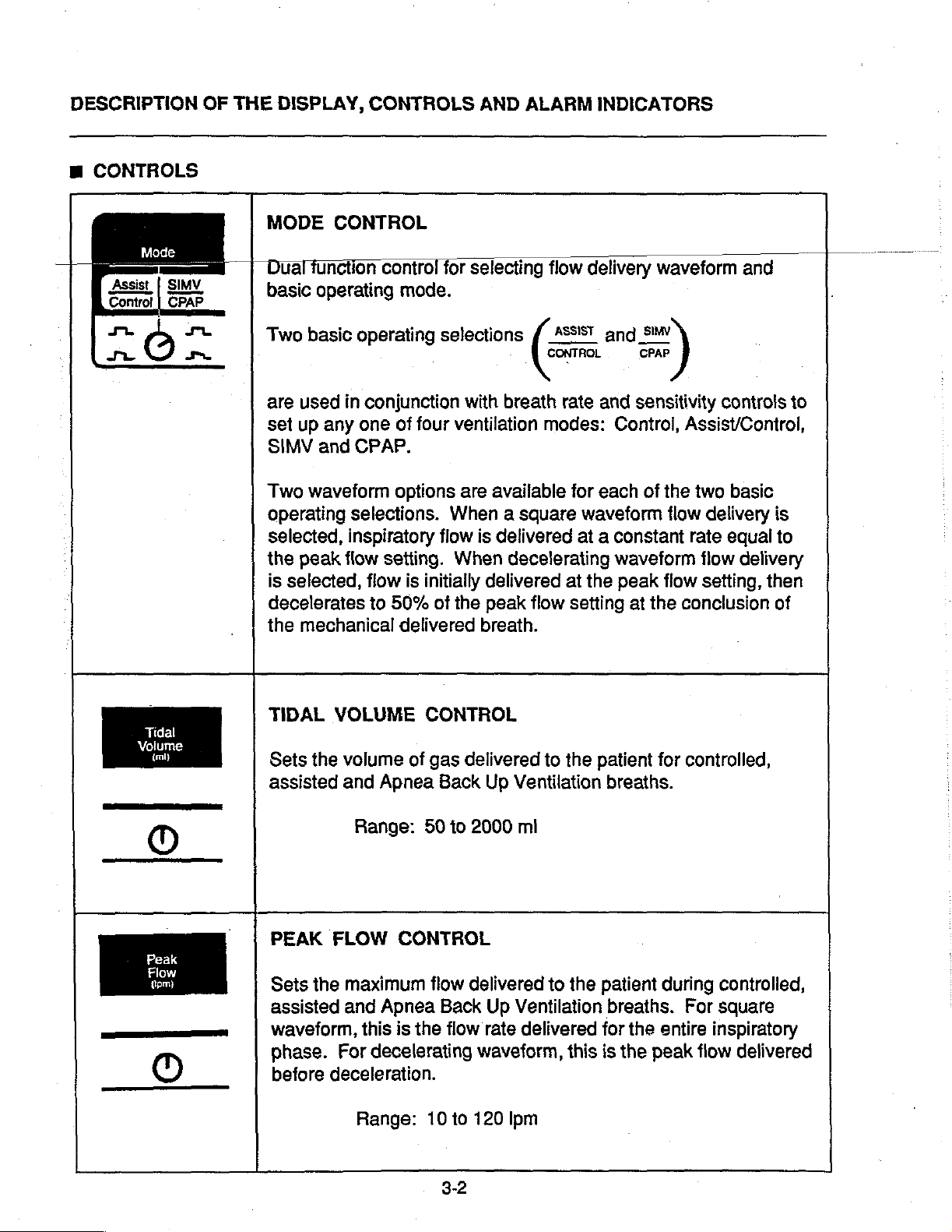
MODE
Dual
basic
Two
are
set
SIMV
Two
operating
selected,
the
is
selected,
decelerates
the
CONTROL
function
operating
basic
used
up
any one
and
waveform
peak
mechanical
control
operating
in
conjunction
CPAP.
selections.
inspiratory
flow
setting.
flow
to
for
mode.
selections
with
of
four
ventilation
options
is
50%
delivered
are
When a square
flow
When
initially
of
the
selecting
available
is
delivered
delivered
peak
breath.
flow
(=
CONTROL
breath
modes:
decelerating
flow setting
delivery
and
rate
and
for
each
waveform
at a
constant
waveform
at
the
waveform
引
CPAP
sensitivity
Control,
peak
at
Assist/Control,
of
the
two
flow
rate
flow
the
conclusion
and
controls
basic
delivery
equal
flow
delivery
setting,
then
to
is
to
of
Tidal
Voll
KM
~
O
Peak
Flow
(Ut
TIDAL
Sets
assisted
ㅣ
PEAK
Sets
assisted
waveform,
phase.
before
VOLUME
the
volume
and
Range:
FLOW
the
maximum
and
this
For
deceleration.
Range:
of
Apnea
CONTROL
Apnea
is
decelerating
CONTROL
gas
delivered
Back
50
to
2000
flow
delivered
Back
the
flow
10
to
3-2
to
Up
Ventilation
mi
to
Up
Ventilation
rate
delivered
waveform,
120
lpm
the
patient
the
for
this
for
breaths.
patient
breaths.
is
the
the
during
entire
peak
controlled,
controlled,
For
square
inspiratory
flow
delivered
Page 21
_©_
Rate
MM
ーー
©
PEEp
eno)
.
7
_—-
ce
a
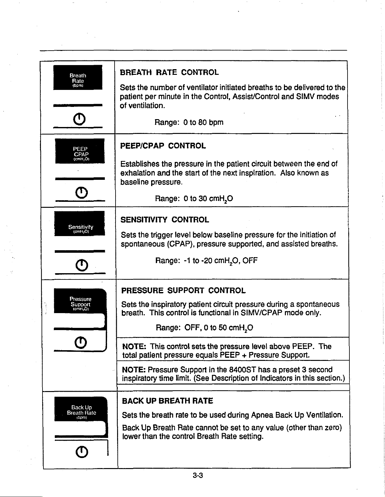
BREATH
Sets
the
patient
of
ventilation.
PEEP/CPAP
Establishes
exhalation
baseline
SENSITIVITY
Sets
spontaneous
RATE
number
per
minute
Range:
the
and
pressure.
Range: 0 to
the
trigger
CONTROL
of
ventilator
in
the
0 to
CONTROL
pressure
the
start
CONTROL
level
below
(CPAP),
initiated
Control,
80
bpm
in
the
of
the
next
30
cmH,O
baseline
pressure
breaths
Assist/Control
patient
supported,
circuit
inspiration.
pressure
and
to
be
delivered
and
SIMV
between
Also
known
for
the
assisted
to
the
modes
the
end
of
as
initiation
of
breaths.
©
PRESSURE
Pressure
Support
lO
Back
Up
Breath
Rate
tbpml
Sets
breath.
NOTE:
total
NOTE:
inspiratory
BACK
Sets
Back
lower
Range:
the
inspiratory
This
control
Range:
This
patient
the
Up
than
pressure
Pressure
time
UP
BREATH
breath
Breath
the
-1
to
SUPPORT
patient
is
OFF, 0 to
control
control
sets
Support
limit.
RATE
rate
to
Rate
-20
cmH,O,
CONTROL
circuit
functional
50
the
pressure
equals
(See
be
cannot
Breath
PEEP + Pressure
in
the
Description
used
be
Rate
OFF
pressure
in
SIMV/CPAP
cmH,O
8400ST
during
set
to
setting.
during a spontaneous
mode
level
above
Support.
has a preset 3 second
of
Indicators
Apnea
any
Back
value
only.
PEEP.
in
this
Up
Ventilation.
(other
than
The
section.)
zero)
3-3
Page 22
DESCRIPTION
w
ALARMS
High
Peak
Pressure
temH.0O)
OF
THE
DISPLAY,
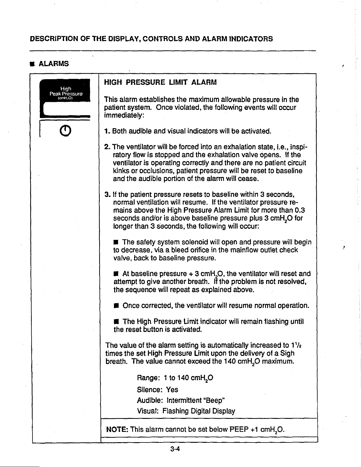
HIGH
This
alarm
patient
immediately:
1.
Both
2.
The
ratory
ventilator
kinks
and
.
If
the
normal
mains
seconds
longer
CONTROLS
PRESSURE
establishes
system.
audible
ventilator
flow
or
the
patient
ventilation
above
than 3 seconds,
Once
and
will
is
stopped
is
operating
occlusions,
audible
and/or
portion
pressure
the
is
AND
LIMIT
the
maximum
violated,
visual
be
High
indicators
forced
and
correctly
patient
of
resets
will
resume.
Pressure
above
the
ALARM
ALARM
the
following
into
an
the
exhalation
and
pressure
the
alarm
to
baseline
If
the
Alarm
baseline
following
INDICATORS
allowable
events
will
be
activated.
exhalation
valve
there
pressure
are
will
be
will
cease.
within 3 seconds,
ventilator
Limit
will
occur:
pressure
state,
opens.
no
reset
pressure
for
more
plus 3 cmH,O
in
will
occur
i.e.,
If
patient
to
baseline
than
the
inspi-
the
circuit
re-
0.3
for
M
The
to
decrease,
valve,
Ш
At
attempt
the
M
Once
m
The
the
The
value
times
breath.
safety
back
baseline
to
give
sequence
corrected,
High
reset
button
of
the
the
set
High
The
value
Range: 1 to
Silence:
Audible:
Visual:
system
via a bleed
to
baseline
pressure + 3
another
will
repeat
the
Pressure
is
activated.
alarm
setting
Pressure
cannot
140
Yes
Intermittent
Flashing
solenoid
orifice
pressure.
breath.
as
ventilator
Limit
exceed
cmH,O
Digital
will
cmH,0,
explained
indicator
is
automatically
Limit
“Beep”
open
in
the
mainflow
the
If
the
problem
will
resume
will
upon
the
the
140
Display
and
pressure
outlet
ventilator
is
above.
normal
remain
delivery
cmH,O
flashing
increased
maximum.
will
check
will
reset
not
resolved,
operation.
until
to
1'/2
of a Sigh
begin
and
NOTE:
This
alarm
cannot
be
set
below
3-4
PEEP
+1
cmH,
0.
Page 23
Low
Peak
Pressure
{emtt20)
|
9
Low
PEEP/
CPAP
Pressure
ο
χο
O
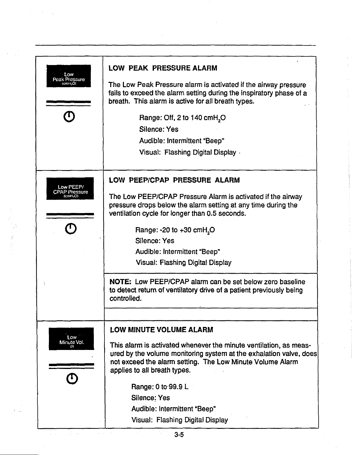
LOW
The
tails
breath.
LOW
The
pressure
ventilation
:
PEAK
Low
Peak
to
exceed
This
Range:
Silence:
Audible:
Visual:
PEEP/CPAP
Low
PEEP/CPAP
drops
cycle
Range:
Silence:
PRESSURE
Pressure
the
alarm
alarm
is
Off, 2 to
Yes
Intermittent
Flashing
PRESSURE
below
for
longer
-20
to
Yes
ALARM
alarm
setting
active
the
for
140
Digital
Pressure
alarm
than
+30
cmH,O
is
activated
during
all
breath
cmH,O
“Beep”
Display
ALARM
Alarm
setting
0.5
seconds.
if
the
the
inspiratory
types.
-
is
activated
at
any
time during
airway
phase
if
the
pressure
of
a
airway
the
Audible:
Visual:
NOTE:
to
detect
controlled.
LOW
‘Low
Minute
Vol.
m
This
ured
not
applies
Low
return
MINUTE
alarm
by
exceed
is
the
the
to
all
Range: 0 to-99.9
Silence:
Audible:
Intermittent
Flashing
PEEP/CPAP
of
ventilatory
VOLUME
activated
volume
breath
monitoring
alarm
types.
Yes
Intermittent
“Beep”
Digital
alarm
drive
ALARM
whenever
setting.
L
The
“Beep”
Display
can
be
of a patient
the
minute
system
at
Low
set
below
previously
ventilation,
the
exhalation
Minute
Volume
zero
baseline
being
as
meas-
valve,
Alarm
does
Visual:
Flashing
Digital
3-5
Display
Page 24
DESCRIPTION
OF
THE
DISPLAY,
CONTROLS
AND
ALARM
INDICATORS
High
Breath
Rate
{bpm)
Apnea
Interval
{sec.)
HIGH
The
(spontaneous
|
9
APNEA
This
or
audible
is
BREATH
High
Breath
Range: 3 to
Silence:
Audible:
Visual:
INTERVAL
alarm
spontaneous)
initiated.
sets
and
visual
Apnea
Range:
Silence:
Audible:
Visual:
RATE
Rate
plus
the
are
10
Flashing
ALARM
alarm
machine)
150
Yes
Intermittent
Flashing
apnea
sensed
alarm
Interval
to
60
Yes
Intermittent
is
activated
exceeds
bpm
“Beep”
Digital
time
interval.
within
is
activated
alarm
Digital
is
seconds
“Beep”
Display;
the
Display
If
the
selected
and
Apnea
active
in
if
the
alarm
no
breaths
all
modes.
total
breath
setting.
(either
time
interval,
Back
Up
rate
machine
an
Ventilation
"AP"
alternates
FLOW
The
ducer.
operation
Depression
alarm
Depression
until a flow
ventilator.
TRANSDUCER
8400ST
If
the
of
Ш
An
audible
“.--”
appears
window.
m
The
Monitor
and
Breath
for
60
transducer
is
designed
flow
transducer
the
ventilator,
alarm
in
section
Rate.
of
the
Alarm
seconds.
of
the
Alarm
DISCONNECT
to
sounds
the
Low
Silence
Reset
assembly
with
operate
assembly
the
will
with
following
Minute
sequentially
button
button
is
again
Apnea
Volume
Interval
ALARM
or
without
is
disconnected
will
occur:
display
will
silence
will
defeat
connected
setting
the
alarm
only
the
the
flow
trans-
during
setting
audible
to
display
I:E
Ratio
audible
the
alarm
Page 25
ALARM
SILENCE
ALARM
LOUDNESS
Sitence
Reset
e
)
Allows
nal.
period
NOTE:
power
button
sumed.
ALARM
Resets
no
ventilator
Will
ALARM
Located
audible
the
Activating
will
to
for
longer
not
operator
restore
Duration:
During
the
ventilator,
3-5
seconds
RESET
the
visual
exists.
operation.
reset a Ventilator
LOUDNESS
on
the
alarm
to
this
control
the
60
an
alarm
alarm
Resets
Defeats
rear
panel,
level.
temporarily
audible
seconds
condition
continuous
will
indication
disable
again,
silence
Apnea
Inoperative
the
within
alarm.
resulting
depression
the
of
Back
flow
transducer
alarm
the
audible
the
60
second
from
of
alarm
any
Up
condition.
loudness
until
alarm
ventilation
disconnect
knob
alarm
silence
loss
of
electrical
the
alarm
power
condition
is
which
to
normal
alarm.
varies
sig-
silence
re-
the
D
Low
Inlet
Gas
CEB
Ventlnop.
LOW
Alarm
pressure
drops
and
visual
alarm
a)
b)
c)
d)
Range:
INLET
is
below
can
Low
Clogged
Regulator
System
GAS
activated
drops
16
Ventilator
be
caused
inlet
inlet
pressure
Silence:
Audible:
Visual:
74dB
below
PSIG
gas
malfunction
to
84dB © 1
ALARM
whenever
17
PSIG
(1.12
Inoperative
by
any
pressure
filter
iransducer
No
Continuous
Flashing
3-7
meter
ventilator
(1.19
kg/cm?).
kg/cm?)
of
LED
for 1 second,
state
the
following
malfunction
Tone
interna!
will
be
signaled.
conditions:
system
If
this
pressure
an
audible
gas
The
Page 26
DESCRIPTION
«ib
Low
Inlet
GERD
Vent
Inop.
OF
Gas
THE
DISPLAY,
VENTILATOR
This
delivery
patient
The
following
*a)
*b)
c)
*
These
ventilator
been
CONTROLS
INOPERATIVE
alarm
Ventilator
condition
and
activate a safety
to
breathe
Inoperative
conditions
Loss
of
electrical
Extended
PSIG
cm?)
Asystem
system,
corrected.
(1.12
for i sec.
either
are
recoverable
will
resume
AND
causes
spontaneously
state
occur:
power
low
ventilator
kg/cm?)
failure
or
is
detected
electrical
Ventilator
normal
ALARM
ALARM
the
ventilator
system,
from
will
be
inlet
gas
greater
or
operation
than
by
the
mechanical,
Inoperative
INDICATORS
to
cease
allowing
“room”
activated
pressure,
ventilator
once
the
air.
24
PSIG
conditions,
the
normal
non-apneic
if
any
less
(1.68
control
conditions
of
the
than
kg/
The
gas
16
have
Silence:
]
Audible:
Visual:
“CIRC”
This
faults
pressure
pressure
displayed
alarm.
transducer
alarm:
DISPLAY
alarm
m
While
than
longer
detects
by
comparing
transducer
mismatch
in
The
Inspiration:
in
29
than
a)
Loss
b)
Loss
c)
System
Continuous
Flashing
possible
pressure
occurs, a “CIRC”
the
“Monitors”
following
and
the
machine
the
inspiratory
cmH,O
100
above
msec,
of
Electrical
of
Iniet
failure:
Alarm
LED
patient
measurements
and
the
machine
display
differences
pressure
phase,
or 9 cmH,O
the
alarm
Power:
Gas
Pressure:
no
circuit
pressure
message
window
between
transducer
if
the
below
will
yes
no
or
pressure
from
transducer.
will
along
the
machine
activate.
with an
airway
pressure
airway
transducer
the
airway
be
visually
pressure
will
activate
pressure
Ifa
audible
the
is
more
for
3-8
Page 27
“CIRC”
DISPLAY
m
Exhalation:
(Cor't)
While
than
longer
Once
tion
machine
PEEP
10 - 12
an
attempt
mismatch
pressures
mal
The
a)
b)
in
29
than 1 second,
activated,
phase
ventilation.
following
with
pressure)
control.
seconds,
to
condition
drops
Blocked
Occluded
breathing
the
exhalation
cmH,O
above
the
the
higher
fed
If
the
the
allow
the
below
conditions
airway
or
kinked
circuit
phase,
or 9 cmH,O
the
alarm
ventilator
to
mismatch
safety
patient
no
longer
PEEP
pressure
is
of
the
the
exhalation
and
to
exists
+ 3
can
cause
inspiratory
if
the
machine
below
will
activate.
immediately
two
pressures
servo
condition
exhalation
breathe
cmH,O
sensing
continues
spontaneously.
and
the
the
this
alarm
port
or
expiratory
pressure
airway
forced
(either
for
purposes
valves
higher
unit
will
to
be
is
pressure
to
the
exhala-
airway
for
greater
will
be
opened
When
of
the
two
resume
activated:
limb
of
more
for
or
of
than
nor-
*
in
the
c)
NOTE:
the
0.05
rise
to
patient
“CIRC”
lieved.
the
ventilator
not
resolved,
been
Transducer
pressure
Silence:
Audible:
Visual:
When
to
0.1
100
cmH,O.
airway
alarm
Once
implemented.
failure
transducer)
Flashing
the
airway
Ipm
pressure.
notification, a solenoid
the
pressure
resets
the
process
(either
No
Intermittent
pressure
Purge
The
pressure
Approximately
and
attempts
"BEEP"
Digital
Flow
causes
is
relieved
will
repeat
airway
Display
sensing
seen
opens
back
to
cycle
until
pressure
port
becomes
the
manometer
on
the
manometer
10
seconds
and
pressure
to
baseline
again.
corrective
or
machine
from
If
the
action
blocked,
pressure
is
not
the
is
re-
+3
cmH,O,
blockage
has
to
is
Page 28
DESCRIPTION
OF
THE
DISPLAY,
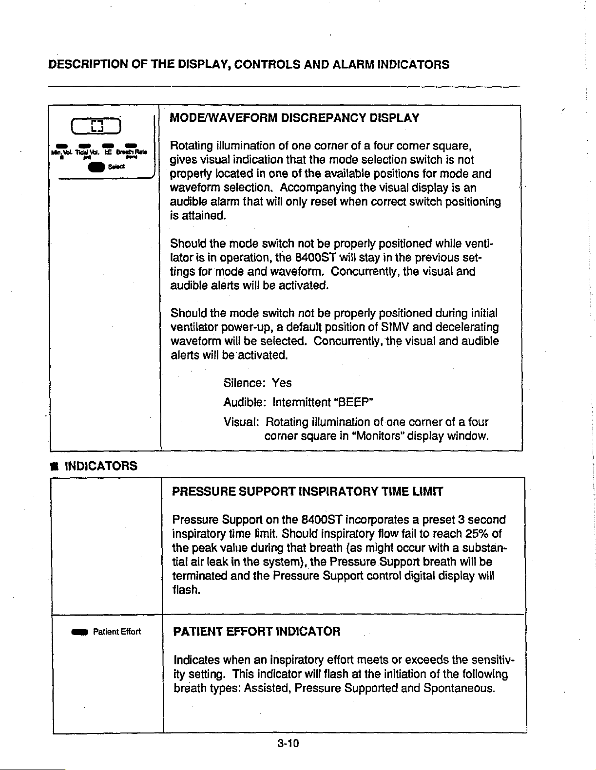
MODE/WAVEFORM
CONTROLS
AND
ALARM
DISCREPANCY
INDICATORS
DISPLAY
M
INDICATORS
Rotating
gives
properly
waveform
audible
is
attained.
Should
lator
tings
audible
Should
ventilator
waveform
alerts
PRESSURE
illumination
visual
located
selection.
alarm
the
is
in
operation,
for
mode
alerts
the
power-up, a default
will
will
be
Silence:
Audible:
Visual:
of
indication
in
one
Accompanying
that
will
mode
mode
switch
the
and
waveform.
will
be
activated.
switch
be
selected.
activated.
Yes
Intermittent
Rotating
corner
SUPPORT
one
corner
that
the
mode
of
the
available positions
only
reset
when
not
be
properly
8400ST
not
square
INSPIRATORY
will
Concurrently,
be
properly
position
Concurrently,
“BEEP”
illumination
in
of a four
selection
the
stay
“Monitors”
corner
visual
correct
positioned
in
the
the
positioned
of
SIMV
the
visual
of
one
TIME
square,
switch
for
mode
display
switch
previous
and
corner
display
LIMIT
positioning
while
visual
during
decelerating
and audible
of a
is
not
and
is
an
venti-
set-
and
initial
four
window.
Pressure
inspiratory
the
peak
tial
air
terminated
flash.
em
Patient
Effort
PATIENT
Indicates
ity
setting.
breath
Support
time
value
leak
in
and
EFFORT
when
This
types:
on
the
limit.
Should
during
the
the
an
Assisted,
that
system),
Pressure
INDICATOR
inspiratory
indicator
3-10
8400ST
inspiratory
breath
the
Pressure
Support
effort
will
flash
Pressure
incorporates a preset 3 second
flow
fail
to
(as
might
Support
control
meets
at
Supported
or
the
initiation
reach
occur
with a substan-
breath
digital
exceeds
of
and
Spontaneous.
25%
will
display
the
sensitiv-
the
following
of
be
will
Page 29
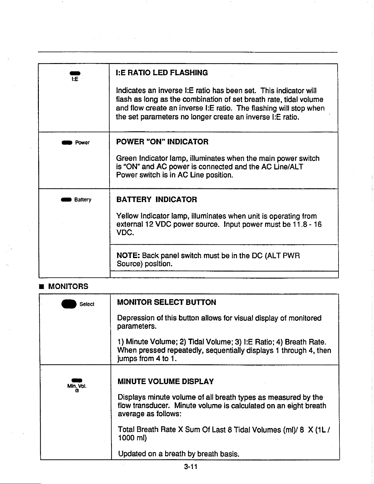
-
EE
RATIO
LED
FLASHING
m
MONITORS
am
Power
am
Battery
O
+.
Indicates
flash
as
and
flow
the
set
POWER
Green
is
“ON”
Power
BATTERY
Yellow
external
VDC.
NOTE:
Source)
MONITOR
an
inverse
long
as
the
create
parameters
"ON”
Indicator
and
switch
Indicator
12
Back
position.
an
INDICATOR
lamp,
AC
power
is
in
INDICATOR
lamp,
VDC
SELECT
power
panel
l'E
ratio
combination
inverse
no
AC
switch
BUTTON
l'E
longer
illuminates
is
connected
Line
position.
illuminates
source.
must
has
been
of
set
ratio.
create
when
when
Input
be
in
set.
breath
The
an
inverse
the
and
power
the
This
rate,
flashing
main
the
AC
unit
is
operating
must
DC
(ALT
indicator
tidal
volume
will
stop
l'E
ratio.
power
Line/ALT
switch
be
11.8 - 16
PWR
will
when
」
from
Depression
parameters.
1)
Minute
When
on
Min,
Vol.
jumps
MINUTE
Displays
flow
transducer.
average
Total
1000
Updated
Breath
mi)
of
this
Volume;
pressed
from 4 to
VOLUME
minute
as
on a breath
repeatedly,
follows:
Rate X Sum
button
2)
Tidal
1.
DISPLAY
volume
Minute
by
3-11
allows
of
volume
Of
breath
for
visual
Volume;
sequentially
all
breath
Last 8 Tidal
3)
:E
types
is
calculated
basis.
displays 1 through
display
Ratio;
as
Volumes
4)
measured
on
of
monitored
Breath
an
eight
(ml)/8 X (1L/
Rate.
4,
by
the
breath
then
Page 30

DESCRIPTION
an
Tidal
OF
Vol.
THE
TIDAL
Displays
volume
a
DISPLAY,
VOLUME
tidal
monitoring
breath
by
CONTROLS
DISPLAY
volume
system.
breath
basis.
for
AND
all
breath
The
ALARM
types
tidal
INDICATORS
as
measured
volume
display
by
the
is
updated
on
Range: 0 to
-
=
Breath | Rate
EE
RATIO
Displays
and
by
breath
will
BREATH
Displays
eight
formula:
the
expiratory
display
the
breath
8
Breaths/Sum
DISPLAY
value
time
basis.
Range:
RATE
If
- - -
-.
DISPLAY
average
average)
9999
m!
calculated
for
machine
breath
1:1.0
breath
for
Of
The
as
rate
is
to
99,
rate
all
breath
Last 8 Breath
the
breaths
set
to
or
1:0
per
types
ratio
between
only.
"0",
then
to
99:1
minute
according
Periods
inspiratory
Updated
KE
(calculated
(min)
on a breath
ratio
window
on an
to
the
time
following
Updated
NOTE:
tected
zero,
tion
will
m
MISCELLANEOUS
AIRWAY
Displays
on a breath
If
an
inspiration
within
the
apnea
begin.
PRESSURE
airway
Range: - 20
the
Apnea
alarm
pressure.
by
breath
(mechanical
interval
will
be
DISPLAY
to
140
3-12
basis.
or
spontaneous)
setting
initiated
cmH,O
and
the
Apnea
breath
Back
is
rate
not
will
display
Up
ventila-
de-
Page 31

Manual
MANUAL
BREATH
BUTTON
Used
Tidal
settings.
ratory
ignored.
Manual
state.
insp.
Hold
INSPIRATORY
When
occur
the
first.
pressure
to
deliver a single,
Volume,
Manual
or
minimum
Manuai
Breath
ihis
button
after
the
button
lation
During
interval
inadvertent
SIGH
is
During
valve
will
from
the
inspiratory
timer
apnea
“ON/OFF”
Waveform
Breath
exhalation
Breath
is
non-functional
HOLD
is
depressed
end
of
the
released
the
inspiratory
remain
the
will
or 6 seconds
airway
hold,
also
be on
alarms.
BUTTON
operator
and
Peak
requests
phases
available
BUTTON
and
next
volume
hoid,
closed
to
pressure
both
hold
initiated
Flow
are
which occur
of
all
in all
modes
during
both
allow
the
to
Ventilator
held,
an
mandated
has
elapsed,
the
flow
reading
manometer.
breath
prevent
controlled
per
during
breath
of
inspiratory
valve
of
rate
breath
breath.
contro!
types
ventilation.
Inoperative
breath
whichever
and
static
timer
stacking
panel
the
inspi-
are
hold
will
until
either
occurs
the
exha-
inspiratory
and
apnea
and
Activates
once
equal
equal
matically
cmH,O)
modes
AC
LINE
ALT
PWR
SOURCE
12-16
VDC
AC/DC
Switches
external
the
automatic
every
to
to
100
1'/2 x the
the
Peak
increased
during a Sigh
of
ventilation.
Range:
SWITCH
power
power
breaths.
Tidal
source
supply.
Flow
to
1'/ x set
breath.
75
to
3-13
Volume
setting.
Sigh
The
3000
from
function
Sigh
breath
setting,
The
high
value
Sigh
function
mi
AC
LINE
allowing a Sigh
is a controlled
delivered
pressure
(up
to a maximum
available
to
12
VDC
at a
limit
alternate
breath
breath
flow
rate
is
auto-
of
140
in
all
Page 32

DESCRIPTION
OF
THE
DISPLAY,
CONTROLS
AND
ALARM
INDICATORS
DATA
LINK
HOURS
DATA
Provides
HOURMETER
The
is
operated.
hour.
actual
nance
POWER
Power
cord
DC
LINK
.
optical
hourmeter
activated
and
INPUT
whenever
The
The
hourmeter
usage
schedules.
MODULE
module
encloses
.
connection
records
meter
hours
turns
RECEPTACLE
the
is
allows
as
well
AC
fuse
the
package
.
of
the
8400ST
total
hours
ventilator
non-resettable
the
clinician
as
for
power
On(l)
of
is
AC
and
establishing
and
for
over
to
other
ventilator
line
records
to
determine
Off(O),
current
devices.
operation.
or
12VDC
to
routine
accepts
protection.
-
battery
the
whole
the
mainte-
power
It
Allows
emergency
for
attachment
or
transport
of
an
external
application.
12
VDC
power
supply
for
3-14
Page 33

SECTION
4
Assembly
Instructions
8400ST / 8400STi
Volume
Ventilator
Service
Manual
Page 34

Page 35

SECTION
ASSEMBLY
4
INSTRUCTIONS
Prior
to
setting
Ventilator,
and
understand
Cautions
the
and
6
up
the
8400ST
operator
Section 6 -
Notes.”
1.
directed
the
Then
>.
this
İ
pins
diagonal
shown.
to
“
3.
onto
04820)
place
screws
with
Volume
must
first
“Warnings,
Assemble
on
Addenda
go
to
step 2 on
page.
(P/N
04825)
corners
Finger
secure.
Install
ventilator
stand
and
with
(P/N
9/16"
Allen
read
stand
page
A-1
Section.
tighten
(P/N
secure
two
(2)
03275)
wrench.
as
in
as
in
NOTE:
position
to
in
Alignment
ventilator
stand.
pins
(P/N
in
place
一
for
4.
Install
MicroBlender
female
bracket
ventilator
(P/N
04820).
5.
Attach
supply
09520)
adapter
then
connect
adaptorto
outlet
croBlender
other
hose
to
fitting
lator.
hose
oxygen
(P/N
00060)
inlets.
04875)
attachment
the
3800
into
dovetail
provided
stand
one end
hose
(P/N
to
90°
elbow
(P/N
00066),
elbow
auxiliapy 一 一
of
3800
and
end
of
supply
DISS
at
Next,
(P/N
hose
(Not
back
connect
02899)
assembly
to
shown.)
Male
of
on
of
Mi-
the
venti-
air
and
blender
一
一
WARNING:
WHEN
DER
8400ST
CONNECT
BLENDER
AUXILIARY
BLENDER
TION
OXYGEN
FLOW
4-1
USING
IN
CONJUNCTION
VOLUME
WILL
SETTINGS
THE
P/N
09520,
HOSE
OUTLET
AUXILIARY
ENSURE
DELIVERY
3800
VENTILATOR,
ASSEMBLY,
OF
MICROBLEN-
WITH
THE
VENTILATOR/
OF
THE
OUTLET
ACCURACY
AT
THE
THE
VENTILATOR.
THE
ALWAYS
TO
THE
BLENDER.
CONNEC-
OF
LOWER
6/97
Page 36

ASSEMBLY
WARNING:
ASSEMBLY
INSTRUCTIONS
6.
Install
Humidifier
into
female
provided
tor
Stand
04820).
7.
Wick
and
Heater
Assembly
as
follows:
OF
THE
HUMIDIFIER
the
Heated
Controller
dovetail
on
Ventila-
(P/N
Installation
Module
Instructions body.
c)
Insert a new
below.
packaged,
*
Peel
*
“Pop”
*
Insert
top
*
Gently
meets
3/8
below
bend
of
For
open
wick
wick
of
main
top
inch
the
or
wick
wick
the
individually
sterilized
bag.
into
through
Do
not
insert
body.
push
the
cap.
of
the
wick
main
fold
exposed
by
forcing
following
wick:
cylindrical
bottom
wick
Approximately
will
body.
it
further.
the
wick
through
in
until
extend
Do
not
portion
steps
shape.
of
main
it
HEATER
TION
OTHER
MAY
TER
FEED
TION
a)
or
b)
MODULE
OF
THE
THAN
CAUSE
SYSTEM
OF
THE
Inspect
center
is
tip
card
and
Twist
main
facing
the
body
the
AND/OR
WICK
IN A SEQUENCE
DESCRIBED
A
FAILURE
AND
HEATER
metal
of
occluded
water
top
cap.
replace
top
cap
so
that
rear
of
INSER-
BELOW
OF
THE
MALFUNC-
MODULE.
feed
tube
If
the
tube
deformed,
or
with
new
clockwise
the
inlet
the
Heater
WA-
in
is
dis-
Top
onto
port
Module.
bent
Cap.
the
is
d)
Float
Apply
assembly
Float
e)
Hand-tighten
Cap
Heater
8.
Attach
midifier
Outlet
Controller
ports
pad
should
even
pressure
for
insertion
Assembly.
the
Assembly
Module.
the
Heater
with
positioned
be
free
Dual
on
the
Module
inlet
the
as
shown.
of
damage.
to
upper
into
Float
Humidifier
to
lower
Bottom
the
Hu-
and
float
Page 37

00423
04709.
To
Heated
Inlet
20225
(Labeled~"To
09534
\
|
N
|
Humidifier
09531
09531
09532
To
Ventilator
Outlet
|
04709
Port
Flow
Humidifier")
Exhalation
\
Valve
20005
20107
(Diaphragm
not
09531
;
09413
'
09413
10081R
Transducer
(not
included)
Body
pictured
20107)
Out
09531
Assembly
TH
2
===
In
=
OIE
N
=
n
*
ο
Transducer
/
ο
ὁ
ο
O
OO
—,
—
기
ㅇㅇ
1
Connector
\
©
A
-
04709
|
09532
Fa
0%
P/N
10172
Kit
(autoclavable)
20225
09531
04709
09534
00423
Patient
Patient
Circuit
90°
Mainflow
22mm
Breathing
includes:
“Wÿye”
Tubing - 30"
Elbow
adapter
Bacteria
I.D.
Cuff
Circuit
w/temp
port
Smooth-Bor®
Filter
Adapter
09532
09413
20005
20107
4-3
Circuit
Watertrap
Exhalation
Exhalation
Tubing - 18"
Vaive
Valve
Smooth-Bor®
Body
Diaphragm
Page 38

ASSEMBLY
9.
Assemble
tor
breathing
a)
Attach
04709)
"Το
of
b)
Attach
(P/N
adapter,
mainflow
c)
Insert
onto
bacteria
male
(P/N
Attach
Humidifier
d)
Connect
(P/N
Heater
one
NOTE:
(P/N
the
Bird
09413)
inspiratory
breathing
densate
from
INSTRUCTIONS
the
8400ST
circuit
90°
to
as
elbow
ventilator
Humidifier",
adapter
directed
one end
09532)
and
to
the
bacteria
the
22mm
outflow
side
filter,
end
of
90°
04709)
entire
into
assembly
Heater
one
end
09531)
to
Module,
leg
of
watertrap
breathing
have
been
and
expiratory
circuit
to
collect
the
humidifier
Volume
follows:
adapter
outlet
with
male
down.
of
short
circuit
the 90°
other
filter
elbow
end
(P/N
female
of
the
mainflow
then
connect
elbow
cuff
adapter
(P/N
to
Module.
of
circuit
outlet
and
of
the
(P/N
circuit
water
incorporated
limbs
excess
gas.
Ventila-
(P/N
labeled
portion
tubing
to
the
09534).
adapter
22mm
00423).
inlet
of
tubing
Humidifier
other
end
to
09413).
traps
into
of
the
con-
tory
other
ing
NOTE:
(P/N
Once
20005)
Exhalation
safety
tab
will
placement.
i)
Connect
patient
to
and
valve
10.
Secure
into
the
patient
sensor
plug
side
of
patient
end
to
watertrap
。
/
the
Exhalation
is
properly
Valve
remaining
the
Assembly, a spring
engage
the
circuit
other
body
end
on
remote
"Wye"
into
the
Humidifier
“Wye”,
one
leg
of
(P/N
9)
09413).
Install
tion
Diaphragm
(P/N
onto
h)
Install
'
last
leg
tion
(P/N
onto
Valve
installed
and
ensure
piece
tubing
of
to
front
of
(P/N
watertrap,
exhalation
of
ventilator.
temperature
and
insert
Controller.
and
remain-
Exhala-
Valve
20107)
ventilator.
Exhala-
Valve
into
the
Body
20005)
ventilator.
Body
the
loaded
the
09531)
sensor
remote
e)
NOTE:
(P/N
20225)
of
Humidifier
f}
Connect
tubing
leg
end
“Wye”
Inspiratory
second
(P/N
09531)
of
watertrap,
to
inspiratory
(P/N
20225).
side
has a large
Temperature
Connect a third
tubing
(P/N
09531)
piece
to
and
side
of
patient
port
Probe.
piece
to
of
patient
remaining
the
other
of
patient
“Wye”
for
attachment
of
circuit
the
expira-
©
11.
Flow
installation:
Transducer
(P/N
a)
10081R)
Install
portion
Fiow
Assembly
connector)
the
ticle
ventilator
and
wise
position.
male
of
the
Transducer
(gray
female
on
front
casting
turn
clock-
to
lock
into
recep-
of
into
Page 39

NOTE:
be
alignment.
NOTE:
sure
the
above
When
heard
Position
lines
right
and
side
properly
the
so
that
of
installed, a click
reference
b)
the
Flow
they
are
the
ventilator
marks
Attach
end
Transducer
Assembly
the
Valve
(P/N
outlet
sure
arrow
body
transducer
pointing
direction
flow.
Transducer
directed
will
opposite
of
Flow
Exhalation
Body
20005)
port.
that
on
of
the
in
towards
as
shown
will
be
into
Be
the
the
flow
is
the
of
gas
Pres-
in
c)
Ensure
secure.
WARNING:
BEFORE
“PRESSURE
CIRCUIT
HEATER
LEAK
DAMAGED
SECTION
For
additional
Heated
MicroBlender,
instruction
L1001 - Bird
L1008 - Bird
PATIENT
INCLUDING
MODULE
DUE
TO
COMPONENTS.
14 - PERFORMANCE
Humidifier
manuals:
Instruction
Instruction
all
connections
APPLICATION,
TEST”
THE
HUMIDIFIER
FOR
MISASSEMBLY
information
and
refer
to
Heated
3800
on
Bird
the
following
Humidifier
Manual
MicroBlender
Manual
are
PATIENT
POSSIBLE
OR
(SEE
TEST)
the
Bird
3800
AIR
Page 40

Page 41

SECTION
5
Overview
Ventilator
of
the
System
8400ST
Operation
Volume
8400ST / 8400STi
Volume
Ventilator
Service
Manual
Page 42

Page 43

SECTION
OVERVIEW
m
PNEUMATIC
OPERATION
E
INTRODUCTION
The
8400ST
tronically
vated
range
system
a
main
processor
control
controls
breath
valve
motion
controlled,
device
of
patients.
is
based
processor, a flow
and a display/exhalation
processor.
overall
rate
timing
control
of
flow
5
OF
THE 8400ST
THEORY
Volume
capable
processors
and
Ventilator
pneumatically
of
The
on
three
The
ventilator
and
exhalation
VENTILATOR
OF
is
an
elec-
acti-
supporting a wide
electronic
microprocessors:
valve
main
functions
volume
control
control
control
valve
processor
such
while
valves.
the
the
actual
as
SYSTEM
The
main
Control
gas
the
flow
Exhalation
The
shown
nents
and
OPERATION
pneumatic
electro-mechanical
Valve
delivery
Flow
Control
from
the
main
flow
in
Figure
are
described
keyed
system
and
to
the
patient
Valve.
of
to
the
Exhalation
patient
Valve
gas
1.
The
numbers
is
based
valves,
is
controlled
while
is
controlled
through
Pneumatic
in
the
following
in
on
the
Valve.
all
exhaled
by
the
8400ST
Figure
two
Flow
All
by
the
is
compo-
pages
1.
FIGURE
ЖОСЯ
PRESSURE
SENSE
LINES
1.
PNEUMATIC
SCHEMATIC,
5-1
8400ST
VOLUME
VENTILATOR
Page 44

OVERVIEW
M
GAS
INLET
Blended
gas
connected
The
ventilator
the
3800
MicroBlender
PSIG
mixed
ized,
of
the
cm2)
inlet
gas
the
alternate
delivering
range
to
of
the
tor.
The
incoming
a
Coalescing
liquid
stream.
the
removal
nants.
and
This
filter
bowl. A drain
of
NOTES:
m
Coalescing
filtering
microns
microns.
aerosol
and
OF
THE
FILTER
ILL.
8400ST
(2)
n
VENTILATOR
from
an
external
to
the
Blended
is
designed
pressure
from
flow
30-70
blended
blended
Filter
solid
contamination
accumulated
to
any
other
device
in
excess
PSIG
gas
(2)
particles
filter
is
particles
solid
particles
operating
the
gas
which
is
99.97%
source
Gas
Inlet
to
be
used
at
blender.
source
must
of
(2.10-4.90
inlet
passes
from
provided
liquid
down
down
is
be
capable
75
Ipm
to
the
through
reduces
the
gas
is
collected
for
contami-
efficient
to
.75
to
is
(1).
with
50
When
util-
within
kg/
ventila-
both
in
in
.3
SYSTEM
E
The
ambient
PSIG.
in
the
applied
E
"
Filtered
Accumulator
mulator
augmenting
inspiration
MicroBlender
proximately
pressures
cm2)
deliver
flow
the
phase.
vessel,
panied
shown
OPERATION
RELIEF
Relief
event
Valve
if
the
This
to
the
VALVE(3)
protects
excessive
ACCUMULATOR(4)
gas
then
(4).
is
to
store
the
flow
75
of
50
respectively,
flow
rates
capacity
accumulator
Since
charging
by
large
on
page
(3)
vents
inlet
pressure
the
unit.
passes
The
pressurized
blender
demands.
is
capable
lpm
with
and
35
while
up
to
is
provided
during
the
Accumulator
and
pressure
5-3,
Figure
inlet
gas
exceeds
pneumatic
inlet
pressure
into a 1.1
purpose
flow
of
inlet
PSIG
the
120
the
discharging
of
the
gas
during
The
3800
delivering
and
(3.50-2.45
ventilator
Ipm.
This
from
gas stored
exhalation
is a rigid
variations
2.
to
100
system
is
liter
Accu-
for
high
ap-
outlet
can
extra
is
accom-
as
kg/
in
m
The
flow
of
gas
filter
is
from
the
be
removed
contamination.
and
through
inside
out.
examined
the
coalescing
The
filter
must
internally
for
tions
the
the
5-2
It
should
shown
accumulator
patient
be
noted
in
circuit.
that
the
pressure
Figure 2 occur
and
are
not
transmitted
only
fluctua-
within
to
Page 45

120 —
Flow
ο
(Ipm)
Inspiratory
©
Inspiration
Phase
;
<
Exhalation
Phase
>
T
M
σι
+
©
n
Pressure
一
(PSIG)
D
인
Accumulator
M
REGULATOR(5)
FIGURE
2.
ACCUMULATOR
PRESSURE
WITH
Tim
RESPECT
3.
Pilot
Valve.
4.
Driving
ducer
E
PULSATION
~
TO
PATIENT
pressure
pressure
sensing
DAMPENER(6)
INSPIRATORY
for
actuating
for
the
lines
purge
the
Flow
Trans-
functions.
FLOW
Satety
A
precision
establishes
.
PSIG
used
1.
2.
(1.40
for
the
Aprecise
the
Flow
of
accurate
Driving
Pressure
pneumatic
the
system
kg/cm2).
following
stable
Control
pressure
Line
flow
Purge
supply
Valve
control.
for
Regulator
pressure
This
pressure
functions:
pressure
for
purposes
the
airway
function.
(5)
at
20
is
to
-
The
chamber
200
of
very
turn
in
order
pressure.
tions,
5-3
Pulsation
with a volume
ml.
The
Flow
fast
changes
forces
the
to
maintain a constant
During
pressure
Dampener
Control
regulator
these
fluctuations
(6)
of
in
gas
to
transient
is a rigid
approximately
Valve
is
flow
which
respond
system
flow
occur
due
capable
in
rapidly
condi-
to
the
Page 46

OVERVIEW
OF
THE
8400ST
VENTILATOR
SYSTEM
OPERATION
response
tion
Flow
mizing
M
FLOW
time
Dampener
Control
the
pressure
CONTROL
of
the
acts
Vaive
and
À
Gas
flow
to
the
patient
Flow
Control
electro-mechanical
of
the
electro-mechanical
formed
tling
flow
Valve
to
linear
through a variable
(7).
device.
motion
Regulator.
as a buffer
Regulator
fluctuations.
VALVE(7)
is
controlled
The
driver
required
The
between
valve
Rotary
is
for
poppet
Pulsa-
the
by
mini-
by
the
is
an
motion
trans-
throt-
type
orifice.
brated
tween
the
cm2)
sonic
approximately 3 PSIG
flow
downstream
(210
combination
relationship
cal
used
control
range
approximate
optical
position.
The
flow
The
valve
to
obtain a known
position
system
flow
through
cmH,0)
driver
by
following
delivery
pressure
through
up
to a downstream
the
pressures
of
between
position
the
Microprocessor
flow
and
of
the
valve
resolution
sensor
for
is
designed
and
orifice
the
valve
in
the
patient
features
and
volume
is
detects
table
describes
various
and
relationship
opening.
at
20
PSIG
variable
pressure
(210
is
unaffected
of
up
leads
the
electro-mechani-
flow
to
the
0-120
of 1 Ipm/step.
the
‘zero’
breath
(1.40
orifice
cmH,O).
to 3 PSIG
circuit.
to a known
rate
which
Controller
patient.
Ipm
with
flow
the
method
types:
cali-
be-
With
kg/
is
of
Mass
by
This
is
to
The
an
An
of
BREATH
Volume
Spontaneous
Pressure
Controlled
TYPE
Support
METHOD
Using
the
seguence
settings.
Using
Microprocessor
required
Identical
maintain
the
known
Microprocessor
to
feedback
to
maintain a stable
to
spontaneous
the
OF
relationship
Controller
satisfy
pressure
the
from
the
Controller
support
INSPIRATORY
between
moves
tidal
volume,
airway
breath
pressure
moves
the
PEEP/CPAP
except
setting.
FLOW
valve
the
valve
peak
flow,
transducer,
valve
to
pressure.
the
flow
DELIVERY
position
in a predetermined
provide
and
and
waveform
the
flow
is
controlled
-
flow
as
rate,
to
5-4
Page 47

m
CHECK
VALVE(8)
3.
In
Valve
and
controls
level.
conjunction
(7),
Microprocessor
Airway
Pressure
PEEP/CPAP
with
the
Flow
Controller
Transducer
to
the
Control
(10),
desired
The
orificed
combination
diaphragm
the
patient
This
is
through
ventilator
Ш
EXHALATION
to
is
critical
the
in
B
Check
with
breathing
Safety
an
Valve
the
insure
when
one
the
Valve
inoperative
VALVE(9)
IAE
(8)
works
exhalation
way
spontaneously.
patient
(12)
valve
gas
flow
is
breathing
with
condition.
in
the
when
Additionally,
phragm
taneous
flow.
m
AIRWAY
the
exhalation
acts
as a check
breathing
PRESSURE
to
TRANSDUCER(10)
AS
LAMA
The
Airway
converts
analog
Microprocessor
following
Pressure
airway
signal.
functions:
pressure
This
Control
valve
valve
insure
one
J
Transducer
to
an
signal
is
used
system
dia-
during
electrical
way
(10)
by
for
spon-
gas
the
the
All
exhaled
trolled
of
exhaled
valve
tro-mechanical
forms
processor
1.
2.
is
Closes
circuit
Opens
exhalation
gas
by
the
Exhalation
gases
controlled
the
following
Control:
the
exhalation
during
wide
for
from
the
patient
Valve
through a large
by a linear
actuator.
functions
all
types
at
the
minimum
The
leg
of
inspiration.
beginning
flow
is
con-
(9).
The
poppet
motion
valve
under
of
elec-
per-
Micro-
the
patient
of
resistance.
flow
m
m
m
m
m
m
5-5
PEEP/CPAP
Pressure
High
Low
Low
Detection
Supported
Pressure
Peak
PEEP/CPAP
control
Limit
Pressure
Alarm
of
Patient
Breathing
Alarm
Alarm
Initiated
Breaths
Page 48

OVERVIEW
m
SAFETY
The
safety
Solenoid
(12).
is
system
chamber.
poppet
patient
lost
state,
upper
ambient
Valve
spontaneously
m
During
open,
or
the
chamber
poppet
MACHINE
TRANSDUCER(13)
OF
SYSTEM(11)(12)
system
(11)
normal
passing
pressure
This
and
seals
system.
the
unit
Solenoid
pressure.
THE
8400ST
consists
that
drives
20
to
closes
the
When
is
in a Ventilator
of
the
allowing
from
PRESSURE
p
zz
|
the
operation
PSIG
the
upper
the
inspiratory
electrical
closes,
Safety
This
opens
the
‘room’
ZEZE
Z
|
VENTILATOR
(1.40
safety
of a Safety
Safety
the
solenoid
kg/cm2)
safety
valve
leg
power
Inoperative
venting
patient
air.
Vaive
the
to
the
to
Safety
Valve
valve
of
the
is
inspire
SYSTEM
The
monitors
transducer
the
certain
cessor
sure
within a predetermined
(see
allows
sure
inspiration.
an
monitor
m
The
provides-a
through
This
into
fixed
orifice
-10
blocked,
ducer
Check
the
pressure
OPERATION
Machine
Airway
phases
Controller
signals.
"CIRC
for
drops
audible
AIRWAY
PURGE(14)(15)(16)(17)
ainvay
prevents moisture
the
orifices
(16)
lpm
will
Valve
pneumatic
Pressure
machine
is
used
Pressure
of
inspiration,
compares
The
two
Display"
transducer
in
the
patient
If
this
test
alarm
window.
forward
the
ventilator
purge
pressure
not
exceeds
and
PRESSURE
pressure
airway
pneumatics.
(14)
and
are
calibrated
fiow.
exceed
(17)
system
Transducer
outlet
pressure.
as a safety
Transducer.
the
the
signals
range
in
Section
tolerances
fails,
“CIRC”
must
of
circuit
the
flashes
SENSE
monitor
ků
(ıs
sense
flow
pressure
In
to
the
100
prevents.
purge
of
biended
from
(15)
to
the
gauge
cmH,O.
in
the
drive
line
sense
migrating
and
provide a .05
event
back
event
(13)
This
io
During
Micropro-
two
pres-
agree
pressures
4)
which
and
_pres-
during
unit
sounds
in
the
LINE
16
purge
gas
line.
up
The
two
the
variable
the
line
and
trans-
The
flow
into
airway
pressure.
-
is
Page 49

SYSTEM
PRESSURE
TRANSDUCER(18)
The
System
continuously
kg/cm2)
an
electrical
cessor
mined
pressure
activate
or
the
The
system
tolerance
Ventilator
severity
following
Pressure
monitors
system
analog
compares
is
out
of
the
Low
Inoperative
of
the
conditions
pressure
pressure
range.
Inlet
to
Transducer
the
signal.
this
signal
range,
Gas
out
of
be
out
(18)
20
PSIG
and
The micropro-
to a
If
the
the
controller
Pressure
state
range
can
cause
of
range:
(1.40
converts
predeter-
system
depending
condition.
the
it
to
will
Alarm
on
sure
sense
to
the
and
to
Every
inspiratory
designed
ential
and
to
ing
purge
the
transducer.
zero
urements
independently
nent
m
pressure
allow
purge
moisture
voltage
reference
variations.
DIFFERENTIAL
lines
differential
close
50
interval a microprocessor
off a
seconds
phase,
to
connect
the
the
pressure
from
from
This
can
TRANSDUCER
from
the
pressure
5.0
Ipm
(approx.)
the
purge
both
transducer
5.0
ipm
(2.5
sense
accumulating.
the
differential
voltage
point
so
that
maintain
of
temperature
their
PRESSURE
(20)
Flow
Transducer
transducer
flow
source.
and
during
valves
ports
is
of
(20)
together
ipm
per
lines
During
samples
pressure
then
used
volume
accuracy
and
(20)
an
are
the
differ-
port)
flow
prevent-
this
as
a
meas-
compo-
8
Insufficient
m
Clogged
mw
Regulator
m
PURGE
During
(19)
normal
are
configured
gas
inlet
filter
out
of
VALVES
000
Yoo
operation
supply
calibration
(19)
the
purge
to
connect
the
valves
pres-
K
The
differential
meásures
orifice
through
the
differential
then
volumemetric
both
the
of
the
the
transducer
converts
Tidal
Volume
Pressure
pressure
Flow
Transducer.
pressure. A microprocessor
the
differentia!
flow
rate
and
Transducer
across
increases
and
Minute
the
As
pressure
then
calculates
Volume.
(20)
variable
the
flow
so
does
to
a
Page 50

OVERVIEW
OF
THE
8400ST
VENTILATOR
SYSTEM
OPERATION
m
FLOW
(21)
The
flow
the
following
©
Variable
(a):
The
flow
chambers
Orifice
bends
ates a small
tween
ence
amount
-
transducer.
When a flow
attached
ventilator,
bers
pressure
tial
pressure
pressure
chambers
sends
TRANSDUCER
transducer
components:
(ο)
assembly
(b)
CE
Orifice
transducer
separated
flow
element.
in
the
direction
pressure
the
two
chambers.
in
pressure
of
flow
to
the
are
transmitted
transducer
difference
in
an
analogue
is
passing through
transducer
the
connector
pressures
transducer
the
transducer
ASSEMBLY
consists
of
(a)
Flow
consists
directly
between
signal
Transducer
of
two
by a variable
The
flow
element
of
flow
and
cre-
difference
The
is
properly
port
in
to a differential
(20).
The
measures
which
be-
differ-
related
the
on
the
the
cham-
differen-
the
two
and
then
is
to
the
the
-
digitized
sor.
Since
material
and
cycles,
sure
thus
to
determine
seconds,
the
minute
then
next
О
Pressure
These
respective
bers
ential
O
The
connects
to
the
mation
to
determine
curve.
optical
teristic
ducer.
factory
racy
and
the
flow
whose
remain
the
difference
can
be
the
measured
volume.
displayed
breath
two
in
the
pressure
Flow
Transducer
flow
transducer
the
ventilator,
required
Each
code
calibration
This
and
is
maintained.
“read”
constant
relationship
used
flow
microprocessor
cycle.
Sense
sense
pressure
flow
flow
the
connector
which
calibration
insures
by
the
element
properties
and
flow
These
at
transducer
transducer
but
by
proper
is
for
between
flow
by
the
rate.
the
lines
Every
to a tidal
volumes
beginning
Lines
transmit
of
the
Connector
connector
transducer
also
the
microprocessor
identifies
curve
is
that
microproces-
made
millions
is
microprocessor
provides
calibration
incorporates
of
done
system
from
are
known
of
pres-
known
(b):
two
to
(20).
that
and
four
translates
volume
are
of
the
the
cham-
the
differ-
(c):
not
assembly
the
charac-
trans-
at
the
accu-
a
milli-
and
only
infor-
an
5-8
Page 51

EH
8400ST
The
following
understanding
CIRCUIT
theory
of
operation
8400ST's
BOARDS
and
their
THEORY
may
be
circuit
OF
helpful
boards:
to
OPERATION
you
in
troubleshooting
and
MAIN
Please
D
RESET
O
MICROPROCESSOR:
AND
CLOCK:
R64,
U31
10
circuit,
clear
ram
(R80,R81,R82,&
to
pin
The
The
microprocessors
pin
converters,
referto
C65,
pin
goes
pin 6 is
CLR
U29
start
running.
9,
the
clock
12
20
XTAL2.
the
and
D5
11.
When
LO.
if
this
HI,
line
at
pin
27.
microprocessor
signal
Mhz
clock
the 2 Mhz
U16
BOARD
schematic
form a power
/RST,
pin
the
U28,
This
Q2)
U28
is
generated
is
U22
and
U19
is
LO
READY
pins
signal
to
the
pin 12,
to
output
(CPUA),U33
PCLK
U20.
50010
50012
pin
and
line,
3,
11
goes
microprocessor B U33
the
start
by
from
for
references.
on
delay
11
the
pin 5 goes
and
thru
RESET A line
up.
U31,
pin
(CPUB)
from
for
is a Hl
output
also
the
an
invertor
8284-1
12
OSC,
U31,
pin 2 goes
the
level,
from
and
pin
HI
/RES
goes
IC,
19
RES
then
the
fault
and
on
stage
pin 9 to
LO,
from
sent
XTAL1
to
reset
input,
the
RESET
monitor
releases
the
allowing
crystal
to
the
dual
enable
X1.
the
and
U29
A/D
the
pin
port
it
U22
The
MAIN
from
EPROM
bites
address
pins
39 - 32
decoded
(right
applied
order 8 bits
come
decoding.
bus
when
controlled
microprocessor,
microprocessor
U24.
(270256)
bus
is
multiplexed
(4D10 - AD17,)
with
the
side)
of
U23
to
the
EPROM
of
the
directly
from
The
the
Program
by
the
program
U22
The
EPROM
or
64K
(270512)
with
is
routed
ALE?
address
microprocessor,
U22.
(Address
containing
program
bus.
U22
pins
21 - 28
instruction
Store
5-9
only
ENable
retrieves
is
jumper
with
the
Latch
address
memory
The
the
the
JP2.
data
bus.
to
the
Enable)
chip
high 8 bits
(418 - A115)
is
placed
PSENT
instruction
program
selectable
The
lower 8 bits
The
left
side
information
U24
of
on
the
signal
instructions
to
lower
of
line.
The
along
the
address
without
multiplexed
is
is
read
be
either
of
address
U23
and
outputs
now,
are
with
need
LO,
as
into
the
the
bus
of
AD
the
32K
bus,
high
Page 52

OVERVIEW
©
MICROPROCESSOR
OF
THE
8400ST
Please
A18,
are
CSSSW2,
WR)
peripheral
also
The
5-8
The
switches
7-13
VENTILATOR
MAIN
refer
(Con't.):
A19,
and
decoded
and
enable
input
the
PAL
MODE
from
pins
Front
panel
SW2
so
that
BOARD
to
the
schematic
A110,
into
/CSPAL.
the
microprocessor
output
U25.
switch,
J3
thru
they
A115
Chip
Enables
chips,
SW1,
1-6.
RESET,
SW7
can
be
SYSTEM
50010
50012
are
These
(U16,
is
read
SIGH,
are
latched
read
into
OPERATION
(Con't.)
for
references.
sent
to
U32,
pins
1,2,
CSADC,
lines,
to
into
SELECT,
the
CSMUX1, CSMUX2,
and
the
ReaD
read data
U20, U15, U19, U30, U26,
main
into
Main
from
microprocessor
and
U27
(74HC244)
processor
and
and
MANUAL
,3
and
WRite
write
port
BREATH
from
when
6.
These
/CSSW1,
(AD,
data
to
the
U27)
and
U22
pins
J3
pins
requested.
/
The
Main
processor
Ram
U29.
This
lines
A18
and
A115
and
the
data
lines
RD2,
WR2
lines
potentiometer
Processor
information
This
information
processor
be
dealt
interrupt
and
perform
every
gets
The
board)
transmits
on
goes
exists
on
millisecond,
taken
main
and
the
RXD
to
U11
on the
the
power
1,2,
or
190-193
settings
thru J2
for
requests
with.
/NT7
other
care
processor
the
on the
(receive
which
serial
board,
talks
is
done
using
and
A20
to
from
the
that
then
the
the
multiplexed
is
also
sent
it
is
put
U29
pin
16
to
the
main
tasks
but
32
of
eventually.)
U22
Display
TXD
(most
processor
(transmit
data,
drives
bus
between
the
likely
to
the
Display
the
the
RD1,
A27
„the
Display
the
operator
Display
displays
to
the
on-it's
is a 1
every
tasks
talks
the
main
millisecond
processor
millisecond.
are
to
data,
pin
10)
fiber
processor
fault
processor
data
lines
WR1
lines
address
Processor.
processor
Dual
data
causing
scheduled
the
motor
U33
pin
line
optic
U22
code
lines
sets
on the
Port
lines
processor
over a serial
11)
(J1
pin
interface
and
U33
will
1).
thru
A10
to
from
the
A28
The
switch
are
read
writes
Display
Ram.
so
that
clock
which
it
to
read
(Not
every
in a queue
line
(J1
15).
The
J15.
on
the
shut
down
the
Dual
A17
„the
Main
processor
and
A215
and
into
the
out
to
J2 the
board
Then
when
the
information
triggers
the
panel
thing
and
U3
(on
data
link.
pin
7)and
TXD
If a problem
main
board
with a fault
Port
address
and
the
Display
display
(50000).
the
Main
can
an
pots
is
done
every
the
line
thing
power
It
receives
also
and
code
U3
5-10
Page 53

MAIN
Please
O
MICROPROCESSOR
The
EPROM
(27C256)
bus
32
ALE2
containing
program
address
pins
instruction
ENable
instruction
U33
displays
about
refer
(Cont.):
DISPLAY
U35.
or
is
multipiexed
(AD20 - AD27,)
(Address
only
memory
bus.
21 - 28
is
PSEN2
is
the
display
at a
62
Hz.
BOARD
to
the
schematic 50012
microprocessor
The
EPROM
64K
(270512)
with
the
is
routed
Latch
address
The
(A28 - A215)
placed
signal
read
1666
Enable)
information
chip
U35
high 8 bits
without
on the
is
LO,
into
the
processor,
processor
Hz
rate.
50010
is
with
data
to
along
multiplexed
causes
This
(Con't.)
U33
fetches
jumper
JP3.
bus.
the
left
line,
The
now,
with
of
the
address
need
as
controlled
an
translates
for
selectable
The
The
side
the
U33.
update
references.
the
program
to
lower 8 bits
lower
outputs
are
high
of
decoding.
AD
address
of
U34
(right
applied
order 8 bits
bus
come
bus
when
by the
of
the
into a total
instructions
be
either
of
the
bus,
and
decoded
side)
of
to
the
of
directly
The
program
the
Program
processor,
front
panel
refresh
32K
bites
address
pins
39
with
U34
EPROM
the
from
Store
the
LED
rate
of
from
-
the
U33
The
Display
valve.
O
PAL
WATCHDOG
connector
CIRCUIT:
The
PAL
If
the
correct
U28,
top
bottom
constants
connected
and
pulses
stop
because
conditions
and
pin
slow
condition
A
fast
condition
a
PAL
the
PAL,
the
VENT
This
to
IC,
half
half
are
to
cause
12
even
and
INOP
is
detects
stop
to
processor
done
the
power
U25
is
sequence
checks
set
U28.
coming
they
go
HI
will
will
if
the
if
it
is
condition
also
with
enabled
of
if
the
pulses
by
the
If
the
are
too
U28
pin 5 to
sending a RESET
latch,
restart
watchdog
not
responding
controls
the
Data
board
from
at
pin 3 and
events
resistors
pulses
out
and
to
occur,
pulses
slower
are
of
pin
fast,
then
go
LO
the
only
itself.
NOTE:
timer
occur
the
D/A
that
that
is
passed
the
P1
port
data
is
then a pulse
are
faster
than
R61,
too
5.
If
U28,
causing a VENT
way
is
disabled
then
after
than
99
milliseconds.
R62
and
fast,
U28,
the
pulses
bottom
to
the
processor
to
reset
The
processor
because
the
processor
writing a fault
controls
across
pins 1 thru
written
.45
capacitors
top
are
half
it
the
to
and
is
output
milliseconds.
The
half
too
slow,
times
INOP
and O chips.
is
to
remove
will
it
reads
stops,
code
the
exhalation
J16
8.
read
from
at
pin 14.
The
time
C58,
C60
never
times
or
if
out.
Both
condition,
power.
not
run
without
data
and
waits
3, 4,
or
it.
out,
they
A
from
for
5.
5-11
Page 54

OVERVIEW
O
A/D
OF
THE
8400ST
Please
CONVERTER
The
the
to
R50
Pressure
-VBI
#12V
this
and
RP3,RP4,U17,U18,U19,U20
to
against
42, 43,
goes
overrange
61,
by
RP6
-form
and Proximity
”going
VENTILATOR
MAIN
refer
to
CIRCUITS:
circuits
transducers
digital
to
J17-6,
REF
forms a dual
U21A
digital
into a Vent
70,
an
overrange
(fault
noise
overrange.
convert
numbers
R62
(pins
J4-2,
2.5VREF
J1-19.
make
circuit.
each
44,
52, 53,
or
75,
80, 85).
codes
filters
BOARD
the
schematic
the
and
the
that
J3-16
Machine
The
redundant
one
During
other,
an
if a close
54,
Inop
open
Open
condition
30,
for
the
pressure
SYSTEM
50010
50012
front
panel
generated
the
processor
to
J3-40
Pressure
trom
U3
pin 2 FLOW
same
analog
normal
62,
condition.
circuit
31).
A/D
to
inputs
system.
to
and
match
63, 64, 73,
condition
wipers
due
to
RP1,
inputs.
5.1VDC.
OPERATION
(Cont.)
for
references.
pots
and
pressure
DC
voltages
can
use.
even),
J4-4,
digital
U21B
operation
This
on
pull
RP2,
Vpot
and
are
seen
RP1,RP2,U13,U14,U15,U16
interface
make
data
is
not
found, a fault
or
78)
also
(fault
the
potentiometer
up
resistors
RP3,
D6,D7,D8 & D9
This
is
from
The
inputs
J3
35,37, a 39
Proximity
PRESSURE
at
both
circuit.
up
an
is
read
is
sent
and
happens
codes
RP4,
to
40,
R58, R59,
C14-29,
keep
the
if
signals
analog
Pressure
A/D
identical
and
any
41, 50,
are
limit
A/D
from
voltages
are
pots
System
J17-3
code
the
and
converters,
analog
checked
(32,
ventilator
input
51,
detected
RP5
C30-45
the
Machine
from
J4-6,
33,
is in
60,
and
The
A/D's
signals
The
(U13,U14,U17 & U18)
done
forth
using
A/D
voltages
but
made
oscilloscope. A more
to
and
condition
until
compare
voltage
and
inputs
thru
over
CSADC,
converters
after
of
decode
shorts
power
levels
are
controlled
switch
are
selected
the
switch
the
AD10 - AD17
/RDATD1,
U16,
are
seen
passing
the
the
is
occurs
switch
through
signals
bidirectional
the
only
the
is
removed.
selections
both
by
the
decode
decoders
U20
at
the
observed
failed
into
signals
one
at
and
are
bus,
/ADATD2,WR1,
and
inputs
U13,
sophisticated
data.
too!
that
switch
You
to
and
out
5-12
main
processor
(CSADC,
atime
converted
U15
and
and
controlled
the
MAIN
(left
side)
U14,
U17,
at
the
output
logic
An
ohmmeter
can
help
condition
can
check
see
if
they
of
the
CSMUX1, & CSMUX2).
by
the
analog
into
digital
U19.
processor
you
between
switches
Data
and
of
U13
and
U18,
with
analyzer
here.
and
are the
thru
the
chip
switches
data.
is
sent
by
the
Main
A10
lines
U22.
,U14,
the
to
signal
same
and
U17
no
sense
lowly
would
check
When a Vent
level
the
two
and
into
decode
This
is
back
and
processor
between
Stable
and
be
needed
continuity
are
circuits
also
the
A/D's.
DC
U18,
can
Inop
held
the
be
and
Page 55

MAIN
О
REFERENCE
O
FAULT
MONITOR
Please
CIRCUITS:
U1
from
R1, R2,
the
reference
against
during
SVA,
two
5VA
U3
It
is
processor
refer
generates
the
transducer
and
5VA
supply,
supply
this
its
power
then
it
buffer
and
is
the
amplifiers,
VPOT
the
2.5
reference
will
CIRCUITS:
BOARD
to
the
schematic
both
the
board
R3
divide
and
for
the
supply.
shuts
Volt
halt
The
up
self
itself
respectively
reference
for
with a fault
50010.
50012
5VA
and
9680,
the 8 Volts
4.97
volts
A/D
converters.
processor
test,
and
down
so
the
with a fault
that
the
at
supply.
fault
(Con't.)
for
VPOT
is
the
into
forthe
measures
if
it
is
voltages
the
outputs.
It
monitor
code
70-78.
references.
references.
reference
approximately
VPOT
not
is
circuit
supply.
All
voltages
proper,
code
at
input
powered
and
The 8 Volt
for
these
the
VPOT
compared
80-87.
pins 3 and 5 are
by
if
it
voltages.
5.00
Volts
The
5VA
are
measured
supply
U1
constitutes
the
Va
is
not
correct
supply,
for
is
the
to
the
supply.
the
U2
is a square
If
the
5V,
wave
HI,
and
than
and
stuck
way
pin 9 of
of
(
coupled
charges
cease,
LO
Vent
The
front
the
pot
Volts
is
passed
the
voltage
when
the
down,
HI or
at
pin 7 of
U4
U4
(R30
AC
coupled ) so
through
then
and
also
Inop
VPOT
pane!
50000
opens
at
pin
wave
sensed
the
2.5
and
LO
(R26
and
capacitor
condition.
current
pot
display
then
4,
by
to
at
pin 5 is
left
side
Volt
reference.
if
the
(this
U4
and
R31).
that
capacitor
C7
discharges
the
output
by
sensing a reduction
board
the
this
causes
oscillator
R18 & R19
output
(R22
C7
is
voltage
pin
greater
of
R22
5V
goes
is a fail
and
R27).
Pin
13
if
pulses
C6,
causing
pin 1 to
monitored
is
set
at
the
5-13
whose
2.
is
This
too
condition).
R23).
The
of
are
rectified
pin 7 of
through
be
by
so
pin 5 of
output
is
within
That
is
than
LO
then
causes
high
or
The
VMis
U4
is
present
resistor
LO.
U6
at
of
that
the
U6
pin
output
the
The
tested
applied
U6
2 to
pin 3 is
proper
when
VA
into
ALO
pin
VPOT
becomes
the
2.5
Volt
the
voltage
the
output
too
low,
5VA
is
tested
the
to a differentiator
at
pin
DC
to
be
R35
signal
5.
This
current.
VPOT
load
go
LO.
sent
limits
by
HI.
the
left
side
reference
at
pin 2 to
then
is
tested
the
same
13,
then
D1
and
If
the
causing
here
detects
The
is
650
greater
to
U4
square
of
R17
at
pin 5 is
toggle
the
output
the
same
way
at
they
D2,
pulses
pin
7 to
results
an
open
trimmer
Ohms.
than
the
pin
5.
is
pin
4,
less
up
gets
same
way
at
pin
11
circuit
are
and
be
in
a
on
Ifa
8
Page 56

OVERVIEW
OF
THE
8400ST
VENTILATOR
SYSTEM
OPERATION
MAIN
Please
O
FAULT
D
ALARM
MONITOR
This
switch
test),
set
ventilator
of
fault
14
either a reset
exists,
forcing a VENT
CIRCUIT:
The
from
when
the
switch
left
pins
switch
ALARM?’
U8
alarm
not
HI
LED
INOP*
signal
the
flashing
refer
CIRCUITS
output
and
the
and
14
by
R34
and
breathing
the
fault
monitor
conditions
is
LO
then a fault
then
alarm
latch
side
11 of
pin 3 to
latch
(off),
front
circuit
the
5V
power
is
enabled
ALM
of
R85
U40
has
been
at
ON. Pressing
the
later
and
set
signal
is
applied
panel.
on
BOARD
to
the
schematic
(Con't.):
is
connected
system
(Lo
limit
C8
so
does
system
are
fed
condition
the
output
INOP
is
powered
supply
is
SLNC
R47
go
alarm
the
ALARM“
at
and
through
jost.
SW‘
only
and
its
pressed.
or a VENT
HI. A HI
OFF
processor
R47
to
Q1
This
off.
TROUBLESHOOTING
50010
together
pressure
test).
that
not
to
exists.
(HI
pin 5 will
and
A latch
when
resets
after
output
signal
the
alarm
but
LO,
also
to
form a power
LED
(Con't.)
50012
with
J5-4
This
node
momentary
cause
from
U6
pin 9 without
This
at
pin
RESET
by a supercap
R42
is
the
5V
power
pin
An
INOP*
signals
will
turning
goes
is
made
Vent
pin 1 of
signal
7)
or
be
LO
condition.
and
formed
goes
and
latches
is
turned
13
alarm
at
at
pins 6 and 7 of
silence
the
turn
off
the
to
U9,
to
for
references.
the
J1-5
comparators
has a 1
fluctuations
U6
is
fault
clearing
D3.
by
low
signals
generated
R48
switch
processor
the
alarm
then
driver
blink
second
Inops.
is
connected
the
time
sent
condition
C9
This
maintains
the
two
at
R43.
the
alarm
off.
This
the
(pins
with
silence
back
to
U8
to
by
timer
Exhalation
U5
pins 1 (Hi
time
of
Vors
At
C8
the
so
delay.
to
U31
pin
(LO
at
both
halves
(Vb)
and
is
an
top
parts
The
alarm
OFF
is
connected
processor
from
the
processor
2, 1 of
U7
the
U8)
will
drive
the
power
to
turn
function
on.
The
where
Vent
U10
the
pin
the
Inop
Valve
limit
constant
because
bottom
that
all
If
U6
pin
6.
At
U31
pin
6)
of
U28
charged
alarm
of
U8,
and
silence
at
J3-14,
to
that
the
will
cause
the
on
does
ALARM"
and
its
VENT
output
LED
3,
of
half
if
on
if a problem
not run
with
both a checksum
both
pass
internal
103
indicate a faulty
or
RAM
exists
it
will
you
memory
shut
can
on
the
bus
down
and a CRC
be
assured
of
the
processor).
between
with a fault
that
processor
code
(cyclical
the
U11 and
105
through
redundancy
Eprom i is
is
checked
5-14
U8,
good
on
U9,
and
108.
check)
(fault
power
U10,
the
The
Eprom
at
power
codes
up also
6, 7 if
processor
on,
not).
(fault
.
is
checked
if
these
The
codes
will
100-
Page 57

The
to
plug
processor
address
frequency
of
HI
have
duty
These
up
the
O
POWER
only
way
in
an
acts
lines.
of
going
twice
cycle
pulses
the
sguare
IC's
also
ventilator
to
troubleshoot
Eprom
Starting
the
SUPPLIES
filled
like a binary
with
line
before
at
the
number
contain
(fault
Please
of
waves.
codes
refer
TROUBLESHOOTING
the
with
NOP
counter.
A0,
it.
clock
pulses
some
105 - 108).
POWER
to
address
instructions
and continuing
Note
that
frequency
than
RAM
memory
the
schematic
bus
Signals
the
BOARD
can
A0 - A7
due
to
line
inside,
(Con't.)
and
make
into
the
be
observed
to
A415,
are
not
the
ALE
before
50022
it.
and
50020
for
sense
U24,35
each
solid
decoding.
A8 - A15
this
references.
out
socket.
at
address
hi
levels,
is
tested
of
the
U24,35
Each
will
it
with a scope
Then
line
but
look
upon
the
Eprom
is
half
are a burst
burst
will
normal,
powering
is
the
50%
The
power
through
goes
to
capacitors
valve
and
is
casting.
7,8. A preregulated
board
supply.
Va
voltage
filtered by
-BIAS
positive
O
OVERVOLTAGE
CIRCUIT
U1
senses
resistors
shorts
blows
comes
the
AC / DC
the
bridge
C4,
motors.
applied
C9
is
by
R1
at
is
C2.
SUPPLY
to
Neg
an
R2
and
out
(crowbars)
the
fuse
in
from
switch
rectifier
and
CS.
This
This
goes
to
O1,
the
its
output
voltage
J1-9
(5Vunreg)
]
generated
This
is
sent
is
generated
voltage
overvoltage
R3.
F1.
generator.
Upon
the
the
Transformer
at
J8
through
at
J5.
The
voltage
to
D3
and
5V
regulator
filter,
and
is
sent
to
sense
from
the
AC
to
the
main
from
condition
overvoltage,
Vm
supply
DC
is
then
mounted
it
is
sent
to
the
(or
the
on
(input
through
fuse
voltage
called
more
to
fault
early
DC)
line
board
+5v
supply
the
5V
U1
triggers
to
J9
and
F1.
The
gets
Vm
and
powers
filtering
on
the
monitor
dropout
at
J14-1,2.
supply
5V
by
the
main
of
by
D1,
and
through
SCR
regulator).
then
AC
or
DC
filtered
rear
board
on
the
D2
U2.
by
the
C7 and C8
of
the
by
the
main
5V
and
UZ
Q2
and
This
J14-
isa
5-15
Page 58

OVERVIEW
O
REFERENCE
(
MICROPROCESSOR:
OF
THE
8400ST
Please
CIRCUIT:
U10
reference.
reference.
R20
motor
Q4
monitored
This
the
VENTILATOR
POWER
refer
to
is
the 2.5
It
The
divide
and
voltage
processor
the 2.5
current
U8
are
thru
will
BOARD
the
schematic
Volt
reference
also
is
used
2.5
voit
Volt
reference
used
to
divider
be
shut
U3
pin
14
SYSTEM
50020
50022
supply
in
the
reference
from
pin 2 of
supply.
generate
stage
R17,
down
if a failure
with a vent
OPERATION
(Con't.)
for
references.
and
it
generates
Exhalation
is
powered
U10
the
VEXH
R18
is
drive
into
to
J1-19
inop
detected.
circuit
by
the
1.13
Volts
voltage
to
the
condition
the
for
Vm
of
12vde.
A/D
1.13
Volt
voltage
supply.
for
the
flow
It
circuits.
thru
Q3
R19,
is
or
by
The
clock
microprocessor
main
The
microprocessor
U5.
(270256)
bus
is
-
32
the
ALE
containing
program
address
U3,
pins
program
Program
microprocessor,
The
over a serial
line
and
exists
main
signal
board
The
(AD30 - AD37,)
motor
processor
through
EPROM
or
64K
multiplexed
(Address
only
address
memory
bus.
The
21 - 28
instruction
Store
receives
on
the
ENable
processor
data
serial
is
generated
U3,
pins
18,
J1-11.
fetches
is
jumper
(270512)
with
is
Latch
chip
high 8 bits
(A38 - A375)
is
the
instruction
talks
port.
on
the
bus
will
shut
with
the
data
routed
Enable)
information
U5
along
placed
PSEN3
to
It
transmits
RXD
between
down
by
the
12
19.
The
RESET
the
program
selectable
JP2.
bus.
to
the
with
of
the
without
on
the
signal
is
the
(receive
with a fault
to
The
The
left
line.
The
now,
the
address
need
multiplexed
is
read
into
main
processor
on
the
data,
U11
on
Mhz
crystal
pin 9 comes
instructions
be
either
lower 8 bits
lower
side
of
outputs
are
high
bus
of
LO,
as
the
TXD
pin
the
main
code
32K
address
U4
and
(right
applied
order 8 bits
come
decoding.
AD
controlled
processor,
(on the
(transmit
10)
board
1, 2,
X1
and
from
from
EPROM
bites
of
the
bus,
decoded
side)
to
the
of
directly
The
bus
when
by
U3.
main
data,
line.
Ifa
and
190-193.
the
the
address
pins
with
of
U4,
EPROM
the
from
the
the
board)
pin
problem
U10,
39
11)
the
5-16
Page 59

POWER
Please
0
SAFETY
O
FLOW
SOLENOID:
The
condition)
13,
These
provides
The
Purge
MOTOR
The
pins.
refer
safety
or
by a power
signals
Purge
solenoid
DRIVE
Flow
to
solenoid,
by
turn
solenoid
CIRCUIT:
signais
BOARD
the
schematic
the
RESETA
failure
are
sensed
off
spike
is
controlled
are
50020
50022
connected
signal
(it
is
normally
at
pin
protection
is
enabled
by
output
from
(Con't.)
to
J10,
on
1, 2 of
for
with
the
the
Main
U9
for
references.
can
be
J1-11,
U7.
pins 3 and
by
open
with
U7
the
RESETA
processor
turned
the
processor
no
power
power
signal
thru
11,
and
off
(vent
U3
applied).
driver.
also.
J1-17.
U6 output
pin
D5
The
A315
(WR3)
chip,
The
U12.
Drivers
coils.
direction
the
motor
When
across
current
to
reached,
O5
acts
Q6
one
that
This
winding
is
sent
enable
U9.
Flow
Resistor
U11
With
of
motor
is
supplied
the
the
sensing
the
voltage
U13
through
as a noise
circuit
phase
the
winding
is
to
is
to
U6,
pin
the
processor
signals
this
the
phase).
power
motor
functions
of
increase
energized.
from
pack
and
U12
arrangement,
coil
(both
The
from
is
first
winding,
resistor
across
turns
R27,
the
the
and
filter,
motor
current
the
1.
This
enables
to
write
U9
and
U6
go
RP1
act
as
pull
form a switching
current can
plus
and
minus
power
Vm
applied
R29.
the
voltage
R26,
and
identically
is
that
holding
for
the
through
as
the
1.13
maintaining
C27
on,
is
the
to
the
current
Ui13
compares
ohm
down
slows
(the
RED - BLUE
bias
current
on
becomes
torque
U6.
This
data
to
the
peripheral
to
level
translator
ups
on
these
“H”
bridge
be
passed
voltages
WHITE - YELLOW
Q5
regulator
motor
R29.
by
down
of
about
rises,
reducing
the
the
it
is
the
When 1 amp
current
the
response
phase).
is
removed
approximately
motor
line,
and
ICs
lines.
for
can
10V
1.13
the
when
Power
the
through
be
at
rear
is
sensed
volt
current
set
at 1 amp.
through
only
the
WRite
output
U11
and
motor
phase
of
When
phase
in
either
applied
of
of
casting.
applied
across
reference
is
voltage
C26
U13.
only
R31
1.5
amps.
1
to
the
of
The
so
The
FLOW
vaive
at
J7-7
HOME
and
line
goes
comes
to
U3
5-17
from
pin
2.
the
optical
sensor
on
the
flow
Page 60

OVERVIEW
OF
THE
8400ST
VENTILATOR
SYSTEM
OPERATION
POWER
Please
0
EXHALATION
VALVE
CPU B (U33
Board
hex
voltage
relaxed
open.
The
feedback
will
driver
valve
to
signal.
The
with
valve
open
refer
DRIVE
thru
connector
to
the
D/A
between O and
condition
voltage
at
vary
around
U18
pin 1 which
moves
U14
pin 2 which
Velocity
the
D/A
to
move
positions.
to
at
U16
BOARD
the
schematic
CIRCUIT:
pins
1-8) port
U15.
of
the
TP1
is
Pin
1/2
VEXH
the
Magnet
is a high
Coil
feedback
voltage
smoothly
50020
P1
J16.
CPU B sends a digital
This
causes a dc
5VDC
Exhalation
then
applied
9.
This
or
drives
causes
gain
is
coming
and
(Con't.)
50022
controls
to
is
approx.
the
DC
in.
properly from
for
the
voltage
be
felt
Valve.
and
then
changed
6v.
linear
an
electrical
amplifier
coupled
This
closed
references.
at
mixed
exhalation
D/A
U15
signal
into
TP1.
2.5VDC
Ov
is
closed
with
the
into a signal
This
is
ted
valve.
charge
as
feedback
into
U16
loop
system
the
fully
on
the
from
U14
causing
is
and
velocity
at
into
the
As
to
be
to
the
pin 5 to
enables
closed
to
Power
00
an
idle
5v
is
coil
TP5
power
the
sent
drive
be
mixed
fully
to
ff
a
or
fully
that
back
the
Fauit
code
codes
list.
The
pushpull
the
The | BOOST
turn
stay
exhalation
‘
The
31-5,
optical
The
10-28,
210-218,
Power
other
it
closed
exhalation
and
Exhalation
Driver
arrangement
side
below
signal
on
and
ensure
during
cycle.
the
exhalation
sensor
110-112,
U18
is
set
(Pins 5 and
6v.
from
that
the
inhalation
valve
on
switch
home
the
exhalation
Home
line
OUBLESHOOTIN
119
up
as a Differential
8).
CPU C U3
the
exhalatiori
cycle.
passes
EXH
valve
is
read
in
are
valve
One
side
will
pin 3 is
through
HOME"
at
at
US
positioning
valve
and
it
the
line
J6-3
pin
fed
has
is
and
1
problems,
Amplifier.
be
above
to
the
base
enough
Released
board
comes
goes
current
during
from
from
to
U9.
please
Ina
6v
of
J6-5
the
and
Q7
to
to
to
see
5-18
Page 61

The
plug
acts
Starting
the
pulses
the
The
code
only
way
to
in
an
Eprom
like a binary
with
A30,
line
before
at
the
clock
number
motor
236).
ot
pulses
processor
TROUBLESHOOTING
troubleshoot
filled
with
counter.
and
continuing
it.
Note
that
frequency
than
checks
the
address
NOP
instructions
Signals
to
AO - A7
due
the
line
internal
can
be
A315,
are
not
to
the
ALE3
before
RAM
bus
and
into
the
observed
each
address
solid
hi
decoding.
it.
(fault
codes
(Con't.)
make
sense
U5
socket.
at
the
U5
line
levels,
but
Each
220-223),
Eprom
is
are a burst
out
it
with a scope
Then
address
half
the
burst
will
and
the
processor
lines.
frequency
of
HI
have
twice
its
Eprom
is
of
going
(fault
to
TRANSDUCER
O
REFERENCE:
O
VPROX
Please
Three
board
Capacitors
AND
VMACH
PT1
and
voltage
3
purposes:
If
not
fault
refer
terminal
at
and
produce
is
of
PT1
0
60
140
the
zero
be
able
code 9 is
to
the
schematic
regulator
J4 - 9,
TRANSDUCERS:
PT2
1.0
and
cmHO
10,
C5
and
pressure
an
Volts,
PT2
cm
H,O
cm
H,O
and
gain
to
be
generated
11
C4
output
and
the
are
calibrated.
BOARD
9682E
U3
provides
derived
are the
transducers
of
at 5
output
not
from
filters.
1.0
Volt
PSI,
voltages
=
1.00 + 0.05
=
1.85
=
2,98 + 0.10
in
spec.,
If
the
on
the
main
9680
for
references.
the
8V
reference
the
Va
supply
are
powered
per
PSI.
At 0 PSI,
the
output
are
voltage
as
follows
Volts
Volts
Volts
then
the
transducer
transducers
board.
(J4 - 14,
by
the
the
is 6 Volts.
for
don’t
match
to
the
main
15,
16).
8V reference
output
At
pin
calibration
board
will
closely,
a
The
output
0
cm
H,O
2.424
The
0
2.424
output
cm
H,O
Volts
Volts
of
PT1
is
pressure
at
60
cm
of
PT2
is
pressure
at
60
cm
offset
and
amplified
H,O
offset
and
amplified
H,0
5-19
by
the
as
measured
by
the
as
measured
Ri
adjustment
by
U1,
at
R3
adjustment
by
U2,
at
with
gain
J4-6.
with
gain
J4-4.
to
1.250
adjusted
to
1.250
adjusted
Volts
by
R2
Volts
by
Ré
out
to
out
to
at
at
Page 62

OVERVIEW
OF
THE
8400ST
VENTILATOR
SYSTEM
OPERATION
TRANSDUCER
O
VPRS
O
LED'S:
TRANSDUCER:
Please
PT3
per
8V
half
voltage
(if
Please
Seven
microprocessor
the
Pins
the
resistors
of
refer
is
an
PSI
or
supply.
of
Ut
out
the
8V
refer
segment
inputs
J2-35
lower
about
to
the
unamplified
40
mV
R9
is
and
U2
will
be
supply
to
row
for
62
is
DISPLAY
to
the
display
U33
the
segment
to
J2-49
of
displays.
the
segment
Hz.
BOARD
schematic
strain
at
15
PSI.
an
offset
form a differential
1.25
V _
exactly
BOARD
schematic
LED’s
on
the
odd
are
drivers.
9680
9682E
gage
These
adjustment,
0.3
8.000
50002
are
main
driver
the
R7
through
for
transducer
voltages
amplifier
at
zero
Volts).
50000
for
multiplexed
board.
U1
for
inputs
The
(Con't.)
references.
with
are
adjusted
for
PSI
and
references.
Pins
J2-19
the
upper
to
the
segment
R22
are
displays
an
output
proportional
at
20
PSI.
PT3.
4.38 V _
by
current
are
At
the
Display
to
J2-33
row
of
driver
scanned
J4-2,
.06
displays.
limiting
of
2.6
mV
to
the
The
other
the
at
20
PSI
odd
are
U2
for
at a rate
U3,
U4,
and
information.
The
discrete
Time,
independently
powered
powered
powered
O
POT'S
AND
SWITCHES:
Pots
connected
the
VPOT
an
main
due
Breath
R50
main
load
open
board.
to
pull
U5
are
U6
thru
LED's
Rate,
from
directly
directly
from
through
in
board.
pot.
from
from
the
parallel
R39
to
650
The
Open
up
resistors
octal
U11
for
Patient
Minute
J2-14
the
the
5V
supply.
R62
are
and
and
__5.
wipers
wipers
on
5-20
decoders
are
the
transistor
Effort,
Volume,
to
J2-30
DC
supply,
main
board.
the
front
are
powered
R40
are
This
is
are
connected
are
detected
the
main
to
decode
Sigh,
and
Silence
even.
and
The
panel
from
an
adjustment
so that
to
by an
board.
the
digit
array
Low
The
the
controls,
the
J3-16
drivers
Gas,
are
Battery
Vent
Green
the
Power
VPOT
to
main
to
overrange
driver
Apnea,
driven
LED
Inop
and
the
supply
adjust
board
40
and
for
the
digits.
Insp.
using
is
LED
LED
ends
the
can
go
condition
U12
is
is
are
from
total
detect
to
the
」
Page 63

O
POT'S
AND
Please
SWITCHES
Switches
Select
through
Qi
refer
Inspiration
Hexfet
DISPLAY
to
the
(Con't.):
SW1 - SW7,
J3-1
to
J3-14.
is
used
BOARD
schematic
Silence,
Hold
and
to
turn
the
50000
50002
Reset,
Mode
are
displays
(Con't.)
for
references.
Sigh,
connected
off
during a loss
Manual
to
Breath,
the
main
of
power
Mode
board
inop.
5-21
Page 64

Page 65

SECTION
6
Warnings,
Cautions
and
Notes
8400ST / 8400STi
Volume
Ventilator
Service
Manual
Page 66

Page 67

SECTION
WARNINGS,
The
8400ST
operated
personnel
a
licensed
application,
and
understood.
by
NOTES
trained,
under
physician.
the
WARNING:
CONDITIONS
ADVERSELY
OR
PATIENT.
WARNINGS:
6
CAUTIONS,
Volume
should
MAY
AFFECT
Ventilator
qualified
the
direct
WARNINGS,
be
EXIST
supervision
Before
read
clinical
and
THAT
THE
NOTES
should
medical
CAUTIONS,
OPERATOR
be
of
COULD
CAUTION:
damage
Conditions
the
ventilator
equipment.
NOTE: A specific
assist
equipment.
the
operator
may
exist
or
other
point
is
made
in
understanding
that
pieces
to
the
could
of
E
DO
NOT
USE
PRESENCE
ICS
AS A POSSIBLE
ARD
m
EXISTS.
THE
SHOULD
FORMANCE
PLETED
Ш A 8400ST
WHICH
NOT
MEET
OF
8400ST
NOT
BE
CHECK”
(SECTION
VOLUME
IS
NOT
MANUFACTURER'S
SPECIFICATIONS
USED
HAVE
BIRD
UCTS
@
VOLUME
DRY
m
NOT
COVER.
BIRD
UNTIL
BEEN
ALL
MADE.
DISTRIBUTOR
CORPORATION
ALWAYS
OPERATE
VENTILATOR
MEDICAL
ELECTRICAL
REMOVE
REFER
TRAINED
THE
VENTILATOR
FLAMMABLE
EXPLOSION
VOLUME
USED
VENTILATOR
UNTIL A “PER-
HAS
BEEN
14).
VENTILATOR
FUNCTIONING
SHOULD
NECESSARY
CONTACT
OR
BIRD
FOR
THE
WITH
GRADE
SHOCK
GASES.
HAZARD;
VENTILATOR
ALL
SERVICING
TECHNICIAN,
IN
THE
ANESTHET-
HAZ-
COM-
OR
DOES
DESIGN
NOT
BE
REPAIRS
YOUR
PROD-
REPAIR.
8400ST
CLEAN/
DO
TOA
YOUR
BIRD
UCTS
M
LATOR
IT IS
TRAINED
DANCE
PROMPT
DISTRIBUTOR
CORPORATION.
WHEN
THE
IS
CONNECTED
RECOMMENDED
CLINICIAN
AT
ALL
ACTION
OCCUR.
m
FOR
CONTINUED
REPLACE
POWER
ONE
THE
ENTRY
OF
IDENTICAL
ING.
M A FLASHING
PEAK
INDICATES
NOT
ALWAYS
PEAK
OTHER
PEAK
ERLY
THE
PRESSURE
THE
BEEN
PROPERLY
ENSURE
PRESSURE
CRITICAL
PRESSURE
ESTABLISHED
PATIENT
OR
BIRD
8400ST
VOLUME
TO A PATIENT,
THAT
BE
IN
ATTEN-
TIMES,
TO
TAKE
SHOULD
PROTECTION,
FUSE
"OFF"
OR
MODULE
TYPE
IN
ALARM
ALARM
FUSES
ONLY
AND
THE
DISPLAY
LIMIT
ESTABLISHED.
THAT
ALARM
THE
LIMIT
ALARMS
ETC.)
ARE
BEFORE
UNATTENDED.
PROD-
VENTI-
A
AN
ALARM
RAT-
LOW
HAS
LOW
AND
(i.e.
HIGH
PROP-
LEAVING
IN
THE
WITH
6-1
Page 68

WARNINGS,
CAUTIONS,
WARNINGS:
m
BEFORE
“PRESSURE
CUIT
INCLUDING
MODULE
TO
MISASSEMBLY
PONENTS.
FORMANCE
Ш
IT
IS
10172,
CUIT
VOLUME
HAS
USE
m
AND
AND
DAILY.
KIT
BEEN
WITH
THE
ALERT
VISUAL,
PATIENT
TEST”
FOR
(SEE
CHECK)
RECOMMENDED
THE
PATIENT
BE
USED
VENTILATOR.
VERIFIED
THE
OPERATION
FUNCTION,
NOTES
(Continued)
APPLICATION,
THE
PATIENT
HUMIDIFIER
POSSIBLE
OR
AIR
DAMAGED
SECTION
THAT
BREATHING
WITH
840057.
SHOULD
THE
THIS
ACCEPTABLE
OF
EACH
BOTH
BE
CIR-
HEATER
LEAK
COM-
14-
PER-
P/N
CIR-
8400ST
CIRCUIT
ALARM
AUDIBLE
VERIFIED
DUE
FOR
AT
THE
LOWER
THE
VENTILATOR.
Ш
BIRD
DOES
BREATHING
INSIDE
(1.91cm),
M
THE
PHRAGM
FOR
TION
SARY.
TIENT
mW
MANUAL
NON-FUNCTIONAL
TOR
PRODUCTS
NOT
RECOMMEND
CIRCUIT
DIAMETER
LARGE
EXHALATION
SHOULD
EXCESSIVE
AND
REPLACED
OTHERWISE
VENTILATION
BREATH
INOPERATIVE
FLOW
BORE
WEAR
SETTINGS
CORPORATION
TUBING
OF
LESS
TUBING
VALVE
BE
CHECKED
OR
WHEN
IMPROPER
MAY
CAPABILITY
DURING
CONDITION.
THE
USE
WITH
THAN
ONLY.
DIA-
PERFORA-
NECES-
OCCUR.
VENTILA-
OF
OF
AN
3/4”
DAILY
PA-
IS
m
CONSULT
FRACTIONAL
INSPIRED
THE
INSPIRED
OXYGEN
RIAL
MR
MONITOR
TIONS
ANALYZER
ALARMS
DESIRED
E
WHEN
DER
VOLUME
NECT
ASSEMBLY
IARY
BLENDER
TION
OXYGEN
OXYGEN
ANALYZER
BLOOD
WITH
TO
FIO,
USING
IN
CONJUNCTION
VENTILATOR,
THE
OUTLET
WILL
CONCENTRATION
A
PHYSICIAN
CONCENTRATION
(FIO,).
GAS
WITH A CALIBRATED
AND
GAS
DETERMINATIONS.
OXYGEN
AN
ACCURATE
WITH
BE
VENTILATOR/BLENDER
(P/N
AUXILIARY
ENSURE
HIGH
ASSURED
IS
BEING
THE
09520)
OF
THE
3800
ACCURACY
ON
PROPER
MONITOR
OBTAIN
CONCENTRA-
OXYGEN
AND
LOW
THAT
DELIVERED.
MICROBLEN-
WITH
ALWAYS
BLENDER.
OUTLET
TO
THE
DELIVERY
THE
OF
SE-
(FIO,)
THE
8400ST
CON-
HOSE
AUXIL-
THE
CONNEC-
OF
m
UNDER
MINUTE
PRIMARY
BE
USED
BILITY.
TIONS
TIONS
OF 6 LITERS
THIS
Ш
A
ALARM
PORT.
WHEN
LATOR
IT
IS
RECOMMENDED
PEEP/CPAP
LEVEL,
BELOW
(EVEN
PROPER
VISUAL
LEM
OCCUR
SYSTEM.
CASES
VENTILATION
BLENDER
TO
HOWEVER,
WILL
AT
MINUTE
THE
IS
CONNECTED
NOT
THE
WHEN
ESTABLISHMENT
PROVIDES
INDICATOR
OF
EXTREMELY
DEMANDS,
OUTLET
EXTEND
DRIFT
OR
LESS
8400ST
ALARM
TO
SENSITIVITY
PEEP/CPAP = 0cmHLO).
IN
THE
THE
O,
CONCENTRA-
OUT
OF
VOLUME
WHEN
VOLUME
TO A PATIENT,
THAT
ALWAYS
EXCEED
ANOTHER
SHOULD A PROB-
FLOW
PORT
UNIT'S
SPECIFICA-
DEMANDS
USING
VENTI.
THE
LOW
BE
SET
3emH,O,
SETTING
OF
THIS
AUDIBLE/
DELIVERY
HIGH
THE
CAN
CAPA-
TO
Page 69

WARNINGS:
M
ALL
ELECTROMECHANICAL
TEMS
OR
TERNAL
INSIDIOUS,
MANCE
TOR
OUS
FAILURE
MANCE
CAUTIONS:
M
Ventilator.
compatible
MH
ammonia
greater
age
lays.
M
ment,
the
M
are
Do
oxide
liquid
EH
(cloth,
transducer.
the
volume
NOTES:
ARE
FAILURE
CAUSES.
DEGRADATION
WILL
DETECT
CONDITIONS
OR
DEGRADATION.
Do
not
sterilize
The
with
Sterilizing
chloride,
than
2%
to
plastic
(See
section 7 -
As
with
any
care
should
equipment
Bird
Products
compatible
not
wash,
sterilize,
sterilizing
Do
not
insert
brush,
flow
element
readings.
(Continued)
SUBJECT
FROM
UNDETECTED
SIGNIFICANT
internal
sterilization
which
chloride
gluteraldehyde
components
other
in
the
Corporation
with
rinse,
or
immerse
agents.
any
pipe
Such
and
TO
INTERNAL
TO
GUARD
AND
WHICH
the
8400ST
components
includes
Cleaning
piece
be
steam
soak,
cleaner,
action
phenols,
compounds
or
exercised
hospital
autoclaving
pasteurize,
the
cleaning
can
result
SYS-
MALFUNCTION
OR
EX-
AGAINST
PERFOR-
THE
VENTILA-
ALARM
MAY
VARI-
CAUSE
PERFOR-
SOME
techniques.
control
and
of
medical
environment.
Bacteria
CONDI-
Volume
are
dimethyl
and
may
cause
panel
Sterilization.
eguip-
when
moving
Filters
“ONLY”.
ethylene
bacteria
instruments
etc)
into
seriously
in
inaccurate
filters
the
damage
not
dam-
over-
flow
TIONS (SUCH
GAS
TEM
LATOR
WITH
INOP
CAL
STAFF
RESPOND
PROCEDURE
GENCY
E
Do
gun
under
M
Do
openings
E
“Do
into
exhalation
M
“Do
into
flow
E
*Do
exhalation
E
“Do
flow
in
transducer
*Repeated
cause
nents
operation,
cleaning
AS
EXTREME
PRESSURE
FAILURE)
VARIATION
WILL
INTO A VENT
AUDIO/VISUAL
SITUATIONS
SHOULD
WITH A WELL-REHEARSED
TO
PROVIDE
VENTILATION.
not
clean
any
not
spray
or
not
not
transducer
not
valve
not
build-up
of
the
if
procedure.
or
dry
circumstance.
cleaning
on
front
spray
spray
allow
allow
use
cleaning
valve
cleaning
cleaning
shaft
cleaning
of
the
of
residue
ventilator,
care
is
POWER
FORCE
INOP
THE
SHUTDOWN
ALARMS.
WILL
OCCUR!
BE
PREPARED
EMER-
with
high
solution
panel
receptacle.
of
the
solution
assembly.
solution
solution
or
poppet.
solution
cleaning
possibly
not
exercised
agent
on
critical
affecting
OR
OR
SYS-
VENTI-
VENT
CLINI-
TO
pressure
air
|
into
louver
ventilator.
directly
directly
to
pool
on
to
pool
in
can
compo-
in
the
E
Federal
or
on
the
law
order
restricts
of a physician.
this
device
The
to
sale
Volume
by
Ventilator
intended
under
6-3
is a restricted
for
use
by
the
direction
medical
qualified
of a qualified
device
personnel
physician.
Page 70

WARNINGS,
CAUTIONS,
NOTES
NOTES:
E
Tidal
has
attempted
the
peak
been
limited
established
notifies
flashing
tidal
ume
M
Peak
has
atternpted
for
the
ventilator
is
acceptable
the
clinician
ing
the
(flashing
M
Back
tor
has
high
response,
Breath
display.
Back
Rate
has
Breath
flashing
Rate
M
Excessive
a
patient
CPAP
flow
PEEP
of
the
resulting
system
unit
after
tory
breaths.
supported
(Continued)
Volume
flow
selected.
the
tidal
breath
the
clinician
the
tidal
volume
delivered.
for
Up
control
increased
can
(flashing
Flow
tidal
volume
has
of
peak
flow
display)
Up
Breath
attempted
the
tidal
the
Rate
setting
B}
The
Breath
setting.
Rate
control
display.
be
set
circuit
mode,
for a brief
level.
oxygen
in a Ventilator
gas
pressure.
will
automatically
2.5
liters
phase.
This
However,
time
indicator
to
set a tidal
setting
In
response,
volume
rate
volume
Indicator
to
set a peak
selected.
limited
for
that
this
incompatible
indicator.
is
Rate
to
volume
ventilator
operator
Rate
the
setting
However,
to
0.
Volume/Fiow
disconnect
the
system
period
This
could
blender
Flashing - The
and
breath
proportionately
and
of
this
indicator.
display)
Flashing - The
the
peak
tidal
volume,
the
actual
Flashing - A)
set a breath
and
has
to
the
has
below
In
response,
to
setting
will
in
an
exceed
and/or
Inoperative due
To
reduce
has
been
delivered
restriction
under
limited
conditions
breath,
volume
the
peak
incompatible
flow
Limited
flow
limited
number
the
the
as
the
Limit - In
while
effort
too
large
rate
that
ventilator
to
flow,
then
setting
The
limited
is
the
actual
operator
that
is
too
In
response,
flow
to a value
then
notifies
setting
flow
attempted
primary
current
indicated
Back
in
provide
to
the
gas
by
peak
delivered.
The
rate that
settings.
the
Back
in
the
to
the
ventilator
primary
Up
the
the
SIMV/
maximum
maintain
flow
supply
flashing
Breath
in
Breath
event
capacity
to
avoid
this
situation,
the
flow
to
40
in
the
inspira-
will
not
apply
of a pressure
the
unit
will
operator
for
have
has
the
by
vol-
high
the
that
flash-
flow
opera-
is
too
In
Up
set
the
the
of
the
system
low
the
Ipm
to
Sigh
auto-
6-4
matically
has
HI
When
“LED”
indication
HE
When
limit
support
E
Power
power
test
the
1.
Power
alarm
2.
Front
unison
3.
Microprocessors
4.
Flow
position
5.
Second
6.
Front
7.
Ventilator
@
important
deliver
breaths
important
displayed
to
within
E
recommended
nected
from
consume
8400ST
reduce
been
delivered.
“I”
Time
will
flash
every 3 seconds,
of
the
the
pressure
of 3 seconds
setting
to
is
automatically
following
display
up
self
the
ventilator
occurs:
“LED”
is
briefly
panel
control
panel
Selected
volume
within
When
from
the
sounded
LED's
valve
and
exhalation
audible
displays
begins
vs
Displayed
to
note
controlled
410%
to
note
in
the
+5%
of
the
ventilator
that
the
3800
MicroBlender
supply
is
in
the
the
inverse
turns
monitors
the
unit,
flow
to
20
Ipm
exceeds
is
exceeded,
test - subsequent
conducted.
verify
alarm
to
that
that
the
gas.
transport
“E”
Time,
giving
state,
support
will
(On/Off
“ON”
segmentally
inspiratory
the
flash.
switch) a 5
During
and
an
display
communication
returns
operate
the
of
the
exhaled
so that
This
to
“Home”
valve
opens
briefly
illuminate
the
is
not
supply
sounds
Tidal
Volume - It
8400ST
or
set
measured
section,
is
configuration.
will
volume
value.
will
volume.
in
use,
sources
the
10-12
does
not
important
after
2.5
liters
the
[E
Ratio
visual
time
pressure
to
initiating
second
the
test
audible
in
is
accurately
assisted
It
is
also
volume,
be
it
is
continue
as
accurate
be
discon-
ipm
bleed
if
the
to
Page 71

NOTES:
E
This
above
equals
E
Pressure
preset 3 second
Description
EH
When
becomes
Purge
sure
seen
airway
onds
the
safety
(Continued)
control
PEEP.
PEEP + Pressure
Flow
to
rise
on
the
pressure.
from
The
Support
of
Alarms
the
airway
blocked,
causes
to
100
manometer
the
“CIRC”
solenoid
sets
the
pressure
total
patient
Support.
in
the
inspiratory
in
Section
pressure
the
0.05
the
manometer
cmH,O.
is
Approximately
alarm
opens
level
pressure
8400ST
time
has
limit.
(See
3.).
sensing
to
0.1
The
pressure
not
patient
notification,
and
pressure
Ipm
10
port
pres-
sec-
a
is
relieved.
back
resets
blockage
repeat
implemented.
M
Back
(ALT
E
Jí
neous)
Interval
zero, the
Apnea
Once
to
baseline
and
attempts
is
not
until
corrective
panel
PWR
an
Source)
inspiration
is
not
setting
apnea
Back
Up
the
pressure
+3
cmH,O,
to
resolved,
action
switch
detected
the
must
position.
(mechanical
breath
alarm
ventilation
will
is
the
cycle
within
again.
the
be
rate
be
will
process
has
relieved
ventilator
Ifthe
will
been
in
the
DC
or
sponta-
the
Apnea
will
display
initiated
begin.
and
Page 72

Page 73

SECTION
/
Cleaning
and
Sterilization
8400ST / 8400STi
Volume
Ventilator
Service
Manua
Page 74

Page 75

SECTION
CLEANING
mw
VENTILATOR
The
exterior
tor
may
bactericidal
should
agent
(primarily
the
the
№
m
m
m
Ш
louver
M
into
to
potential
inside
DO
ventilator.
DO
sterilizing
DO
DO
agents
receptacle
DO
openings
*DO
exhalation
of
be
wiped
or
be
exercised
pool
the
of
the
NOT
NOT
NOT
NOT
to
NOT
spray
NOT
7
AND
the
germicidal
in
front
for
use
immerse
agents.
sterilize
allow
pool
on
spray
STERILIZATION
8400ST
clean
not
areas
panel),
the
liquid
ventilator.
harsh
ventilator.
bactericidal
in
flow
front
cleaning
on
ventilator.
cleaning
valve
assembly.
Volume
with
an
appropriate
agent.
to
allow
on
the
so as
to
abrasives
ventilator
transducer
of
ventilator.
Care
the
ventilator
to
penetrate
on
in
or
germicidal
solution
solution
Ventila-
liquid
minimize
to
liquid
into
directly
The
flow
transducer
liquid
or
m
m
m
The
the
03210C)
submerged
or
The
with
NOTE:
ing
Ventilator
ing
agents,
ethylene
DO
NOT
(cloth,
flow
DO
nozzle
brush,
sensor.
NOT
to
BREATHING
(See
page
ventilator
humidifier
and
steam
autoclaved
main
flow
steam
For
and
sterilization
System,
literature:
can
heat
pasteurization,
oxide
gas.
insert
use a high
dry the
any
pipe
sensor.
cleaner,
CIRCUIT
4-3
for
diagram)
breathing
module
autoclavable
in
liguid
autoclave
additional
agents,
to
bacteria
ONLY.
of
please
be
sterilized
cleaning
pressure
circuit,
(P/N
sterilize.
filter
information
the
8400ST
refer
instrument
etc.)
gas
not
03210
filters,
may
ethylene
is
compatible
to
by
autoclave
into
the
including
or
be
oxide
on
clean-
Volume
the
follow-
α
*DO
NOT
into
flow
transducer
m
*DO
NOT
on
exhalation
m
*DO
NOT
in
flow
transducer.
*Repeated
cause
nents
operation,
cleaning
gm
The
flushing
agitating
build-up
of
the
procedure.
FLOW
flow
transducer
with a genile
it
spray
allow
allow
use
ventilator,
if
care
cleaning
valve
cleaning
of
the
of
residue
is
cleaning
receptacle.
shaft
cleaning
possibly
not
exercised
TRANSDUCER
can
stream
in a solution
of
solution
solution
or
poppet.
solution
agent
on
critical
be
cleaned
of
soap
directly
to
pool
to
pool
cari
compo-
affecting
in
the
by
water
and
or
water.
L1001-
L1008-
5
Heated
3800
ΕΧΗΑΙ
ASSEMBLY
TRANSDUCER
Care
should
exhalation
transducer
ume
Ventilator.
tions
critical
1.
Apply
and
tive
2.Visually
external)
tion
valve
outlined
components.
topical
wipe
solution
has
Humidifier
MicroBlender
ΑΤΙΟΝ
VALVE
AND
be
exercised
assembly
receptacle
Please
below,
exposed
inspect
to
ensure
been
when
solution
surfaces.
(ie
alcohol)
all
removed.
Instruction
Instruction
FLOW
RECEPTACLE
in
cleaning
and
the
on
the
8400ST
follow
surfaces
that
the
cleaning
to a
clean
is
recommended.
ali
cleaning
instruc-
An
(internal
Manual
Manual
the
flow
Vol-
these
soft
cloth
evapora-
and
solu-
Page 76

Page 77

SECTION
8
Maintenance
Service
Policy
8400ST / 8400STi
Volume
Ventilator
Service
Manual
Page 78

Page 79

SECTION
8
MAINTENANCE
WARNING:
A
8400
VOLUME
WHICH
DOES
MANUFACTURER’S
SPECIFICATIONS
USED
REPAIRS
IS
NOT
NOT
UNTIL
HAVE
MEET
ALL
AND
VENTILATOR
FUNCTIONING
THE
SHOULD
NECESSARY
BEEN
SERVICE
DESIGN
MADE.
NOT
OR
BE
Bird
Products
been
designed
amount
amount
the
variables
of
utilization
of
maintenance.
desired
must
e
Frequency
e
Cleanliness
source.
e
Use
trap/filter.
Corporation
to
provide
frequency
be
considered.
and length
of
compressed
of an
air
inlet
equipment
the
maximum
with
minimum
When
of
maintenance
determining
of
use.
water
has
many
air
CAUTION:
Ventilator
calibrated
trained
M
Every
Every
Every
service
$400
1000
3000
5000
RECOMMENDED
The
8400ST
should
by a Bird
be
technician.
Machine
Machine
Machine
Volume
serviced
Products
Hours
Hours
Hours
Corporation
and
/or
MAINTENANCE
Ventilator
surface
appears
coalescing
CAUTION:
working
“Ventilator
Machine,
-Verify
measurement
than
specified,
Products
Bacteria
replaced
to
flow
limit
(see
The
8400ST
pieces
require routine
of
recommended
Inlet
of
the
to
be
filter
pressure
Inoperative”
Airway,
transducer
Corporation
Filter - The
once
through
page
of
time.
Filter-
inlet
filter
dirty
or
replacement
Dirty
inlet
and
calibration
(see
page
contact
each
filter
8-3).
Volume
Health
Refer
Care
maintenance
to
the
maintenance
SCHEDULE
remove
for
foreign
discolored,
element
filter
can
subseqently
condition.
and
Flow
Transducer
to
8-2).
If
your
Bird
for
repair.
main
flow
year
or
more
exceeds
the
Ventilator,
equipment
over a period
following
intervals.
and
examine
material.
replace with
(P/N
reduce
result
ensure
accuracy
distributor
filter
often
maximum
the
in
accuracy
varies
should
if
the
like
other
will
for
the
internal
If
filter
new
06146).
machine’s
a
calibration
of
more
or
Bird
be
resistance
allowable
Main
Flow
8-1
Bacteria
Filter: 2 cm
H20 @ 60
Ipm.
Page 80

MAINTENANCE
Every
15,000
Machine
AND
Hours
SERVICE
A
complete
minimum
your
Bird
|
service.
machine
of
once
distributor
maintenance
every15,000
or
Bird
will
machine
Products
Corporation
be
required
hours.
at
a
Contact
for
HE
TESTING
INSTRUCTIONS
TRANSDUCERS
NOTE:
conducted
continuously
minutes
stabilize
1.
Depress
turn on
valve
not
After
appear
window.
segment
for
monitor
Backup
The
after
with
temperature
and
the
ventilator.
“Homes”
move
thereafter.
valve
“Homing”, a series
on
the
Release
LED
Breath
running
the
display
SOFTWARE
VERIFICATION:
The
four-digit
Main
PC
Board
displayed
display
2.
Activate
is
number
representing
revision
in
the
is
number
the
2. A four-digit
the
level
window.
3.
Activate
is
number
the
3. A four-digit
AND
following
the
VERIFICATION
FOR
test
ventilator
for
at
top
cover
ALL
least
in
variations.
hold
the
Select
Verify
within 5 seconds
ventilator’s
the
display
Rate.
monitor
Select
must
window
(BBR).
button.
be
and
REVISION
number,
software
monitor
Select
representing
revision
window,
one
(1).
button.
number
Power
will
Select
PC
appear
button.
Board
in
the
number
must
has
been
30
place
button
that
the
and does
of
off
the
BBR
monitor
BBR
be
to
and
flow
dots
will
display
All
7
except
the
level,
is
BBR
display
software
display
8-2
representing
software
monitor
4.
Activate
is
number
representing
revision
the
revision
window.
the
4. A four-digit
the
level
will
window.
5.
Activate
is
number
Off
set
50
cmH20
6.
Activate
is
number
appear
Breathing
should
7.
Activate
is
number
appear
Breathing
should
8.
Activate
is
the
appear
pressure
9.
Activate
and
verify
and
associated
for
Vent
the
5.
This
reading,
in
the
the
6.
The
in
the
monitor
circuit,
read
0.0
the
7.
The
in
the
monitor
circuit,
read 0.00 + 2.00
the
number
in
8.
the
monitor
should
the
that
Inop
and
Display
level
Select
PAL
appear
Select
is
and
monitor
Select
Airway
the
+1.00/-0.50
Select
Machine
the
Select
The
PC
will
button.
number
PC
Board
in
button.
the
Flow
it
should
window.
button.
Pressure
window.
airway
button.
pressure
window.
machine
cmH20.
button.
System
window.
Board
appear
BBR
software
the
monitor
BBR
Transducer
read
BBR
Without
pressure
cmH20.
BBR
Without
pressure
BBR
pressure
The
read 20.0 + 0.5PSI.
Select
all
decimals
button
seven
segment
illuminate
Battery.
once
LED’s
more
in
the
display
display
103
+
display
will
the
display
will
the
display
will
except
Page 81

MAINTENANCE
10.
Activate
and
the
normally.
NOTE:
recalibrated,
through
the
ventilator
If
the
refer
6.0.
AND
Select
transducers
button
should
to
Section
function
need
SERVICE
once
more
to
be
14
steps
3.0
2000
ml’s,
Flow
to
60
observe
Duplicate
circuit.
peak
test
Should
by 2 cmH20
Breath
Ipm.
Turn
reading
with
the
or
more,
Rate
at
12
ventilator
on
manometer.
filter
removed
values
recorded
then
bpm
and
“ON”
from
differ
replace
filter.
Peak
and
NOTE:
ventilator
resistance
M
test - Attach
circuit
expiratory
connect
of
flow
to
Ensure
OFF
test.
Main
flow
inspiratory limb
directly
limb
bacteria
the
patient
“Wye.”
direction.
“Assist/Control”,
manometer
prior
to
bacteria
bacteria
to
of
filter
filter
ventilator
breathing
onto
Observe
Adjust
mode
set
Tidal
reads
zero
with
filter
resistance
of
breathing
outlet.
expiratory
Remove
circuit,
control
Volume
the
then
proper
knob
side
at
NOTE:
Pressure
turned
influence
Bird
available
replacement
calibration
technical
designated
as
Ventilator
Alarm
“OFF”
on
the
Products
upon
parts,
instructions
personnel
by
repairable.
will
go
into a Low
condition,
but
this
test.
Corporation
request,
unless
will
have
will
circuit
descriptions
to
assist
to
repair
Bird
Products
Peak
alarm
no
is
make
diagrams,
and
qualified
units
as
Corporation
Page 82

Page 83

SECTION
9
8400ST
Tools
and
Equipment
List
8400ST / 8400STi
Volume
Ventilator
Service
Manual
Page 84

Page 85

SECTION
8400ST
m
8400ST
1.0
Common
Nutdrivers — (deep
Open
Allen
and
Common
#2
Phillips
Long
Diagonal
Trimpot
Stopwatch
9
TOOLS
15,000
End
Hex
Socket
*/s"
Allen
screwdriver
thin
needle
cutter
adjustor
Tools
Wrenches:
AND
HOUR
wrenches
screwdriver - 8"
EQUIPMENT
OVERHAUL
(Not
available from
socket):
1/2",
7/16",
Driver
nose
Set
[*Ball
(slotted) - 8"
pliers
1/4",
5/16",
he”,
No.
end
long
—
Bird
11/22",
Sha",
99-
85-40
with 7 ”
iong
shank
LIST
RECOMMENDED
Products
5a",
1/2”,
ie”
Ne!
Xcelite
(18
shank
or
cm)
TOOLS
Corporation.)
equivalent:
long
shank]
53/15",
AND
3/0",
EQUIPMENT
*7/ea",
los",
2.0
Special
from
Part
00042
00066
00077
00358
00631
01233
01741
02187
03010R
03234
03389
15127
03884
03414
03800
03913
04124
08929
Bird
Bird
No.
Products
items
required
Corporation
Description
Lubricant
Elbow
inline
s"
Lubricant
22
Connector
opening
22F x 22M x 15F,
BHH
Corona
8400ST
Replacement
Vibre-Tite
6400ST
Connection
7.5
"Wye"
Pressure
Tube
mm
Hi/Low
Alternate
Connector
Male x 15
Heating
Dope
Pressure
Service
*
P/N
*
P/N
*
P/N
Flow
mm
Tapered
Power
4.5
Thread
Assembly
for
the
testing
under
Manometer
mm
mm x ‘/"
Connection, 2 each
Module
Transducer
Kit
8400ST
Locking
Tool
03415,
03416
03426
MicroBlender
Plug - plugs
Source
the
Female, 2 each
tubing,
Kit
consisting
Fixture
Fixture
Safety
Jumper
(DC)
and
calibration
following
required
Test
Compound
Assembly,
Assembly,
Solenoid
BHH
Cable
which
part
numbers:
to
seal
the
Harness
of:
regulator
pressure
Removal/Assembly
temperature
Assembly
bypass
test - flow
sensing
may
water
be
obtained
feed
valve
Tool\
port
in
patient
9-1
Page 86

8400ST
2.0
3.0
TOOLS
(Continued)
Part
No.
09220
09520
10172
09531
10234
10233
Special
Torque
*7/s"
・Adapter
Torque
+
Digital
0 - 30
-1
or
Standard
*
+
Flow
Endotracheal
Thermometer
Pressure
full
Variable
12 - 16
4
function
Anti-static
Anti-static
Anti-static
Anti-static
Anti-static
R.T.V.
8
Ltr
Slant
equipment,
screwdriver 0 -
Allen
wrench
5/32"
Allen,
voltmeter
PSIG
.2
Rigid
Bottle
Tube 0 -
scale
clear
volume
tube
Precision
PSIG
test
compliance
filled
Transducer - 20
transformer 1 -
VDC
calculator - must
mat
wrist
mat
D.I.P.
bags
silicon,
manometer
AND
EQUIPMENT
Description
Flowmeter 0 -
Blender
Patient
Corrugated
fittings
Flow
Prox/Purge
driver
7e"
hex
to
20 - 100
3/a"
drive
increments
lung:
with
22
10
LPM,
tube 7 mm
50° - 120°F
power
spirometer + 2%
supply 5 amp
to
cover
strap
ground
remover
adhesive
LIST
15
Hose
Circuit
Hose
or
its
equivalent
Transducer
Test
tools
pressure
not
made
100
inch/ounce
square
inch/pounds
female
manometer + .05
20
ml/cmH,O + 5%
pounds
0.1
1.D x 20
(9 - 48°
to + 140
140
worktable
connecting
(for
(10kg)
LPM
increments
volis
have
EPROMS
sealant
accuracy
LPM
30"
smooth
Test
Harness
Housing
available
fine
grade
cm
long
non
C}
with 2 temperature
cmH,O
or 1 -
minimum
square
cable
accuracy + .5 at O cmH,O
260
volts
root/memory
and
IC)
or
equivalent
or
its
equivalent
bore
with
by
Bird
PSIG
copperwool
cuffed
with 2 adapters 7 mm x 15
cutis
accuracy
to
Products
probes
fit
22.0
mm
Corporation:
-
to + 2
O.D,
mm
cmH,O
at
Page 87

m
KIT,
This
SERVICE
assembly
TOOL
consists
P/N
P/N
of
03414
the
following:
Description
Qty
03415
03416
Fixture
Fixture
Assy,
Assy,
Flow
Regulator
Valve
Bypass
Pressure
Test
Tool,
9-3
Solenoid
Wrench
Page 88

8400ST
TOOLS
AND
EQUIPMENT
03913
LIST
Test
10233
Hose
Assembly
10234
Slant
Tube
Manometer
P/N
10233
P/N
10234
Proximal/Purge
Flow
Transducer
Test
Test
Housing
Harness
P/N
03389
Pressure
Transducer
Test
Harness
Page 89

SECTION
10
Maintenance
Kits
8400ST / 8400STi
Volume
Ventilator
Service
Manual
Page 90

Page 91

SECTION
10
MAINTENANCE
и
P/N
00114
00138
00274
03288
03372
03373
03374
03375
03516
03901
04876
05038
06146
06194
06195
07803
07849
08880
08934
08963
09603
09632
8400ST
Description
O-Ring,
O-Ring,
O-Ring,
O-Ring,
O-Ring,
O-Ring,
O-Ring,
O-Ring,
Insulator
Tubing,
Plug
Cable
Element,
O-Ring,
Bowl,
Cable
O-Ring,
Gasket,
Tube
O-Ring,
MAINTENANCE
.117 x .040
.176 x .070
.145 x .070
.551 x .070
.72 x .103
.801 x .070
.364 x .070
.301 x .070
Bridge
1/4”x
Gauge
Wrap
Tie
Filter
P/N
P/N
09762
Tie
Wrap
.313 x .051
Flow
Assy,
.924
Connection
Valve/Manifold
Gasket,
Manifold
KIT
Silicone
Rectifier
6”
1.D.
Reinforced
Adjust
09672
Control
Reg
I.D. x .103
Elbow
Filter
Filter
Exhaust
Safety
P/N
KIT
|
|
15127
INCLUDES:
Qty.||
P/N
41109672
11109712
2
||
09740A
1
3||
09754
11110080
2
2
||
15349A
11115053
11115179
11120005
1
11120097
1120197
11120191
10
11120292
1
7
||
15053
1
50060A
Description
Insulator,
Regulator,
Valve,
Assembly
Safety
Tube
Transducer
Exhalation
Manifold
Kit,
Body
Seal
Pad,
Flow
Assembly
Fuse
Exhalation
Thermal
Diaphragm
Gasket,
Transducer
Gasket,
Transducer
Manifold,
Assembly
PCB
Assembly
Receptacle
TO-3
2-25
PSIG
Control
8400ST
Valve
Assembly
Valve
Flow
Transducer
Overhaul
Interface
.875
OD,
.396
OD,
Flow
Transducer
Manometer
Assembly
Valve
Flow
Flow
(Solenoids)
Flow
Qty.
4
1
1
1
1
1
with
1
2
1
1
1
1
1
10-1
6/97
Page 92

Page 93

SECTION
Disassembly
11
8400ST / 8400ST/
Volume
Ventilator
Service
Manual
Page 94

Page 95

SECTION
DISASSEMBLY
M
INTRODUCTION
The
Bird
8400ST
been
-
amount
maintenance.
tor
ucts
Service
Before
cian
eration,
explained
A
can
each
designed
of
utilization
should
be
Corporation
Technicians.
servicing
must
be
warnings,
in
numbering
easily
identity
operation.
11
Volume
to
provide
with a minimum
The
8400ST
serviced
trained,
or
familiar
Section 6 of
system
only
calibrating,
with the
cautions
is
utilized
the
steps
Ventilator
the
maximum
Volume
by
Bird
has
of
Ventila-
Prod-
Hospital/Dealer
the
techni-
design,
and
this
manual.
involved
notes
so
op-
as
that
with
one
CAUTIONS:
m
The
work
Discharge
technician’s
before
working
Board
have
severely
PCB
assemblies
Static
m
Always
power
top
cover.
(E.S.D.)
work
removing
on
ventilator.
assemblies
integrated
damaged
bags
after
unplug
source,
area
must
surface
the
(PCB)
Circuits
must
removal.
power
wall
be
Electro
protected.
must
top
cover
All
Printed
in
the
(IC)
and
by
static
electricity.
be
placed
cord
plug,
before
Static
The
be
grounded
and
while
Circuit
8400ST
can
in
anti-
from
electrical
removing
be
All
If
during
cation
not
met,
tions
before
Assembly
and
Operational
Verifi-
Procedure a suggested parameter
refer
to
“Troubleshooting”
proceeding
with the
instruc-
next
step.
is
11-1
 Loading...