

Page 1
EXA Valve Series Operating Instructions
EXA40, EXA50, EXA60 Valve Operating Instructions
Inappropriate and/or improper installation, adjustment, alteration, service or maintenance can cause
property damage, injury or death. Read the installation, operating and maintenance instructions thoroughly before installing or servicing this equipment.
Read these instructions carefully. Failure to fol-
low them could result in a re or explosion causing
property damage, personal injury, or loss of life. The
product must be installed and operated according to
all local regulations.
Service and or installation must be performed by a
trained experienced service technician.
Disconnect power before installation to prevent electrical shock or equipment damage.
FOR YOUR SAFETY
If you smell gas:
1. Open windows.
2. Do not touch electrical switches.
3. Extinguish any open ame.
4. Immediately call the gas supplier.
FOR YOUR SAFETY
The use and storage of gasoline or other ammable
vapors and liquids in open containers in the vicinity of
this control or other appliance is hazardous.
Installation shall conform with local codes. or in the
absence of local codes, in accordance with the National Fuel Gas Code ANSI Z223.1/NFPA54 or CSA
B149.1 as is applicable, and operated in accordance
with the manufacturer’s instructions. These instructions do not supersede OEM’s installation or operating instructions. Installation, inspection, and replace-
ment must be performed by a qualied installer or
gas supplier.
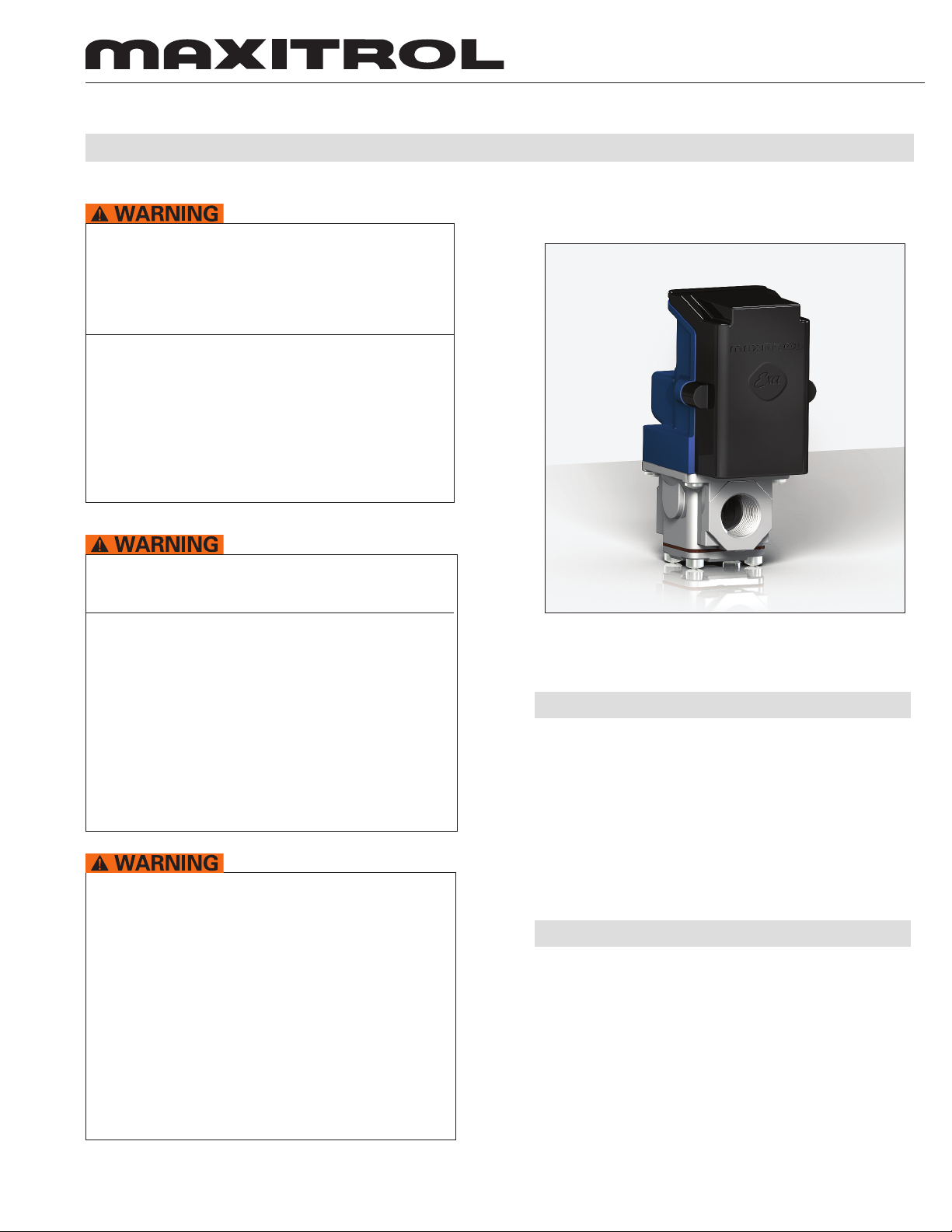
Figure 1: EXA Valve
DESCRIPTION
The EXA series are highly accurate and precise modulating control valves. EXA valves provide repeatable
process control with minimal hysteresis throughout the
entire range of modulation.
The valves’ high re setting and low re setting are user
programmable.
INTERFACE
The EXA valve has a built-in digital controller that provides a seamless interface with
a process controller.
This control must be electrically wired in accordance
with local codes, or in absence of local codes, with
the National Electrical Code, ANSI/NFPA 70 or the
Canadian Electrical Code, CSA C22.1 as applicable.
© 2009 Maxitrol Company, All Rights Reserved
1
Page 2
EXA Valve Series
SPECIFICATIONS
Maximum Inlet Pressure Limits: 5 psi
Power Requirements: 24VAC/DC +/- 10% 50/60hz
NOTE: The 24V power must be isolated from the
control signal.
Maximum Current Draw: 200mA.
Temperature Limits:
-40 to 150ºF Operating
Control Signal:
0-10VDC, 2-10VDC, 0-20mA, 4-20mA, (user selectable)
100KOhm Input impedance
Mounting: Multipoise
Gases:
Suitable for natural, manufactured, mixed gases, lique-
ed petroleum gases and LP gas-air mixtures.
Certications:
EMC (EN 61000:2001)
•
Immunity (61000-6-2:2001)
•
Emissions (61000-6-4:2001)
•
UL Recognized
•
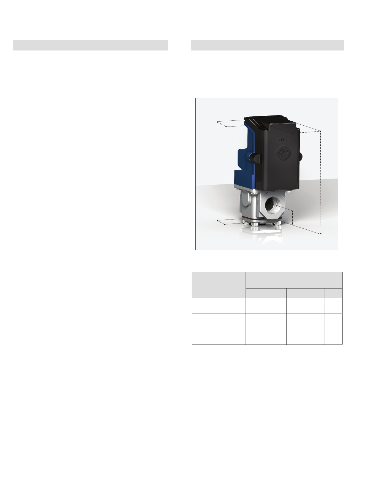
DIMENSIONS
Dimensions are to be used only as an aid in designing
clearance for the valves. Actual production dimensions
may vary somewhat from those shown.
D
E
A
B
C
Figure 2: EXA Valve Dimensions
Enclosure: IP40
Electrical Connection: UL310
Sizes:
EXA40: 3/8”, 1/2” NPT or Rp ISO 7-1
EXA50: 1/2”, 3/4” NPT or Rp ISO 7-1
EXA60: 3/4”, 1” NPT or Rp ISO 7-1
Capacity @ 1” Pressure Drop - 0.64 sp. gr. gas:
EXA40 (3/8”) ............... 217 cfh
EXA40 (1/2”) ............... 242 cfh
EXA50 (1/2”) ............... 434 cfh
EXA50 (3/4”) ............... 524 cfh
EXA60 (3/4”) ............... 733 cfh
EXA60 (1”) .................. 815 cfh
Model
Number
EXA40
EXA50
EXA60
Swing
Radius
4
(102)
4.3
(110)
4.6
(117)6 (153)
(122)1 (26)
(140)
Dimensions
in inches (millimeters)
A B C D E
4.8
5.5
1.3
(34)
1.5
(39)
2.1
(54)
3.4
(87)
4.1
(105)
3.7
(94)
3.7
(94)
4.1
(105)
2.4
(61)
3.3
(84)
3.9
(100)
© 2009 Maxitrol Company, All Rights Reserved
2
Page 3

EXA Valve Series
The EXA valve has full open and full close mechanical
limits. The user can program settings that are within
the valve’s mechanical limits. This added dimension for
sizing and applying the valve is an important feature.
It allows the valve to be set up for an entirely different
net output characteristic (dependent upon supply pressure).
The control signal is “scaled” between the high and low
re setting of the valve. The minimum control signal
will correspond to the programmed low re setting and
the maximum control signal will correspond to the pro-
grammed high re setting.
There are four (4) electrical connections on the EXA
valve. Two (2) are for power requirements and two (2)
are for the control signal (see Figure 4).
Button 1 = High Set / Increase
Button 2 = Low Set / Decrease
Button 1
Control Signal
DIP Switches
Button 2
Power
Requirements
LED Display
Connection Table
Terminal 1 Terminal 2 Terminal 3 Terminal 4
Signal (+) Signal (-) Power 1 Power 2
Terminal 1
Terminal 2
Figure 4: EXA Valve Terminals
Terminal 4
Terminal 3
DIP Switches:
A three (3) position DIP switch is located on the PCB
(see gure 3). Change the signal type and offset by
changing the position of DIP switches. (For DIP switch
position and corresponding current/voltage ranges, see
table below).
Figure 3: EXA Valve Control Signal and Power Requirements
Control Signal:
The control signal drives the EXA valve within a programmable range of modulation.
NOTE: Control signal is polarity sensitive. Connect
control signal positive (+) to terminal 1 and control signal return (-) to terminal 2.
© 2009 Maxitrol Company, All Rights Reserved
DIP Switch Position Table
Control
Signal
0-10V OFF OFF OFF
2-10V OFF ON OFF
0-20 mA ON OFF OFF
4-20 mA ON ON OFF
SW1
Signal
SW2
Offset
SW3
Characteristic
3
Page 4

EXA Valve Series
OPERATION
Step 1: Remove 2 screws holding cover.
Step 2: Connect switched OFF 24 V (AC/DC) power
source to terminals 3 and 4.
Step 3: Set DIP switches to match available control
signal.
Step 4: Connect switched OFF control signal to
terminals 1 and 2. Observe polarity. Note
that the return, or signal ground, must be
connected to terminal 2.
Step 5: Switch Power and control signal ON.
VALVE SETTING
The Exa valve has two (2) buttons and an LED for the
user interface. The buttons are used to set the valve for
high and low re settings (see gure 5).
1. High Fire Setting (LED will be solid red)
2. Low Fire Setting (LED will be blinking red)
3. Operating Mode (LED will be OFF)
HIGH FIRE SETTING - BUTTON #1
To enter the high re setting mode, press and hold button #1 until the LED lights solid red. Release. The valve
is now in the high re setting mode. Buttons #1 and #2
are used to set desired high re setting.
Press or hold button #1 to increase gas ow. Each but-
ton press equates to the minimum available step size
and will increase ow slowly. Holding the button down
auto steps and eliminates the need to continuously
press the button. Use this feature to rapidly increase
the ow.
Press or hold button #2 to decrease gas ow. Each but-
ton press equates to the minimum available step size
and will decrease ow slowly. Holding the button down
auto steps and eliminates the need to continuously
press the button. Use this feature to rapidly decrease
the ow.
To save the high re setting, simultaneously hold buttons #1 and #2 until the LED turns off
NOTE: Controls left in the high re setting mode will de-
fault to the current setting after 5 minutes of inactivity.
Button 1
Figure 5: EXA Valve Adjustment Controls
Button 2
LED Display
LOW FIRE SETTING - BUTTON #2
To enter into the low re setting mode, press and hold
button #2 until the LED light blinks red. Release. The
valve is now in the low re setting mode. Buttons #1
and #2 are used to set the desired low re setting.
Press or hold button #2 to decrease gas ow. Each but-
ton press equates to the minimum available step size
and will decrease ow slowly. Holding the button down
auto steps and eliminates the need to continuously
press the button. Use this feature to rapidly decrease
the ow.
Press or hold button #1 to increase gas ow. Each but-
ton press equates to the minimum available step size
and will increase ow slowly. Holding the button down
auto steps and eliminates the need to continuously
press the button. Use this feature to rapidly increase
the ow.
To save the low re setting, simultaneously hold buttons
#1 and #2 until the blinking LED turns off.
NOTE: Controls left in the low re setting mode will de-
fault to the current setting after 5 minutes of inactivity.
Maxitrol Company
23555 Telegraph Rd., P.O. Box 2230
Southeld, MI 48037-2230 U.S.A.
EXA_MS_EN_07.2009
www.maxitrol.com
© 2009 Maxitrol Company,
All Rights Reserved.
4
 Loading...