

Canon WUX400ST D Pro AV, WUX450 D Pro AV, WUX450 Pro AV, WX450ST D Pro AV, WX450ST Pro AV Command List
...Page 1

MULTIMEDIA PROJECTOR
WUX450 / WX520 / WUX400ST / WX450ST
User Commands
© CANON INC.2013 YT1-1452-001
Page 2

WUX450 / WX520 / WUX400ST / WX450ST User Commands
Table of Contents
Table of Contents ........................................................................................................ ii
1. Overview ................................................................................................................. 1
2. Communication Specifications ................................................................................. 2
Communication Specifications .............................................................................................................. 2
Usable Character Codes ........................................................................................................................ 3
Communication System (Serial) ........................................................................................................... 4
Communication System (LAN) ............................................................................................................. 4
Command Format .................................................................................................................................. 4
Response Format ................................................................................................................................... 5
Other ...................................................................................................................................................... 7
3. Communication Flow ............................................................................................... 8
Command Transmission (PC side) ........................................................................................................ 8
Command Reception (projector side) .................................................................................................... 8
Command / Response............................................................................................................................. 8
Response Reception Timeout ................................................................................................................ 8
Other ...................................................................................................................................................... 8
4. Command List ......................................................................................................... 9
5. Guide to command description .............................................................................. 11
EXAMPLE............................................................................................................................................ 11
6. Command Details .................................................................................................. 13
6AXADJ ............................................................................................................................................... 13
6AXR .................................................................................................................................................... 14
6AXG .................................................................................................................................................... 15
6AXB .................................................................................................................................................... 16
6AXC .................................................................................................................................................... 17
6AXM ................................................................................................................................................... 18
6AXY .................................................................................................................................................... 19
AMBADJ .............................................................................................................................................. 20
AMBLEVEL ......................................................................................................................................... 20
AMBTYPE............................................................................................................................................ 21
ASELA1 ................................................................................................................................................ 21
ASELA2 ................................................................................................................................................ 22
ASELC.................................................................................................................................................. 22
ASELD ................................................................................................................................................. 23
ASELH ................................................................................................................................................. 23
ASPECT ............................................................................................................................................... 24
AUTOPC .............................................................................................................................................. 24
AUTOSETEXE .................................................................................................................................... 25
AVOL .................................................................................................................................................... 25
- -
ii
Page 3

WUX450 / WX520 / WUX400ST / WX450ST User Commands
BLANK ................................................................................................................................................. 26
BRI ....................................................................................................................................................... 26
COLOR_TEMP .................................................................................................................................... 27
COMVER ............................................................................................................................................. 27
CONT ................................................................................................................................................... 28
DGAMMA ............................................................................................................................................ 28
DZOOM_POS ....................................................................................................................................... 29
DZOOM_RAT ....................................................................................................................................... 30
ERR ...................................................................................................................................................... 31
FINE_GAMMA_R ................................................................................................................................ 32
FINE_GAMMA_G ................................................................................................................................ 33
FINE_GAMMA_B ................................................................................................................................ 34
FLTWRN .............................................................................................................................................. 35
FREEZE ............................................................................................................................................... 35
GAMMA ............................................................................................................................................... 36
HDMI_IN ............................................................................................................................................. 36
HDMI_OVSCAN .................................................................................................................................. 37
HUE ..................................................................................................................................................... 37
IMAGE ................................................................................................................................................. 38
IMAGEFLIP......................................................................................................................................... 39
INPUT .................................................................................................................................................. 39
KREP .................................................................................................................................................... 40
LAMP ................................................................................................................................................... 40
LAMPCOUNTER ................................................................................................................................ 41
LMPWRN ............................................................................................................................................. 41
MAIN .................................................................................................................................................... 42
MEMF .................................................................................................................................................. 43
MEMG .................................................................................................................................................. 43
MEMS .................................................................................................................................................. 44
MUTE ................................................................................................................................................... 44
NR ........................................................................................................................................................ 45
POWER ................................................................................................................................................ 46
PRODCODE ......................................................................................................................................... 47
RC ......................................................................................................................................................... 48
RGBGAIN ............................................................................................................................................ 50
RGBOFFSET ....................................................................................................................................... 50
ROMVER ............................................................................................................................................. 51
SAT ....................................................................................................................................................... 51
SAVEIMGPROF ................................................................................................................................... 52
SCRNASPECT ..................................................................................................................................... 53
SHARP ................................................................................................................................................. 53
SIGNAL_INFO .................................................................................................................................... 54
SIGNALSTATUS ................................................................................................................................. 54
TEMP ................................................................................................................................................... 55
TPTN .................................................................................................................................................... 56
7. Error List ................................................................................................................ 57
8. Error Processing .................................................................................................... 58
- -
iii
Page 4

1. Overview
These specifications describe the methods of controlling Projector WUX450 / WX520 / WUX400ST /
WX450ST from PC or other controllers over an RS232C connection or LAN.
Symbol
The following symbols are used in these specifications:
Symbol Description
[ ]
Data in [ ] can be omitted.
|
Same as OR.
WUX450 / WX520 / WUX400ST / WX450ST User Commands
- 1 -
Page 5
WUX450 / WX520 / WUX400ST / WX450ST User Commands
R
2. Communication Specifications
Communication Specifications
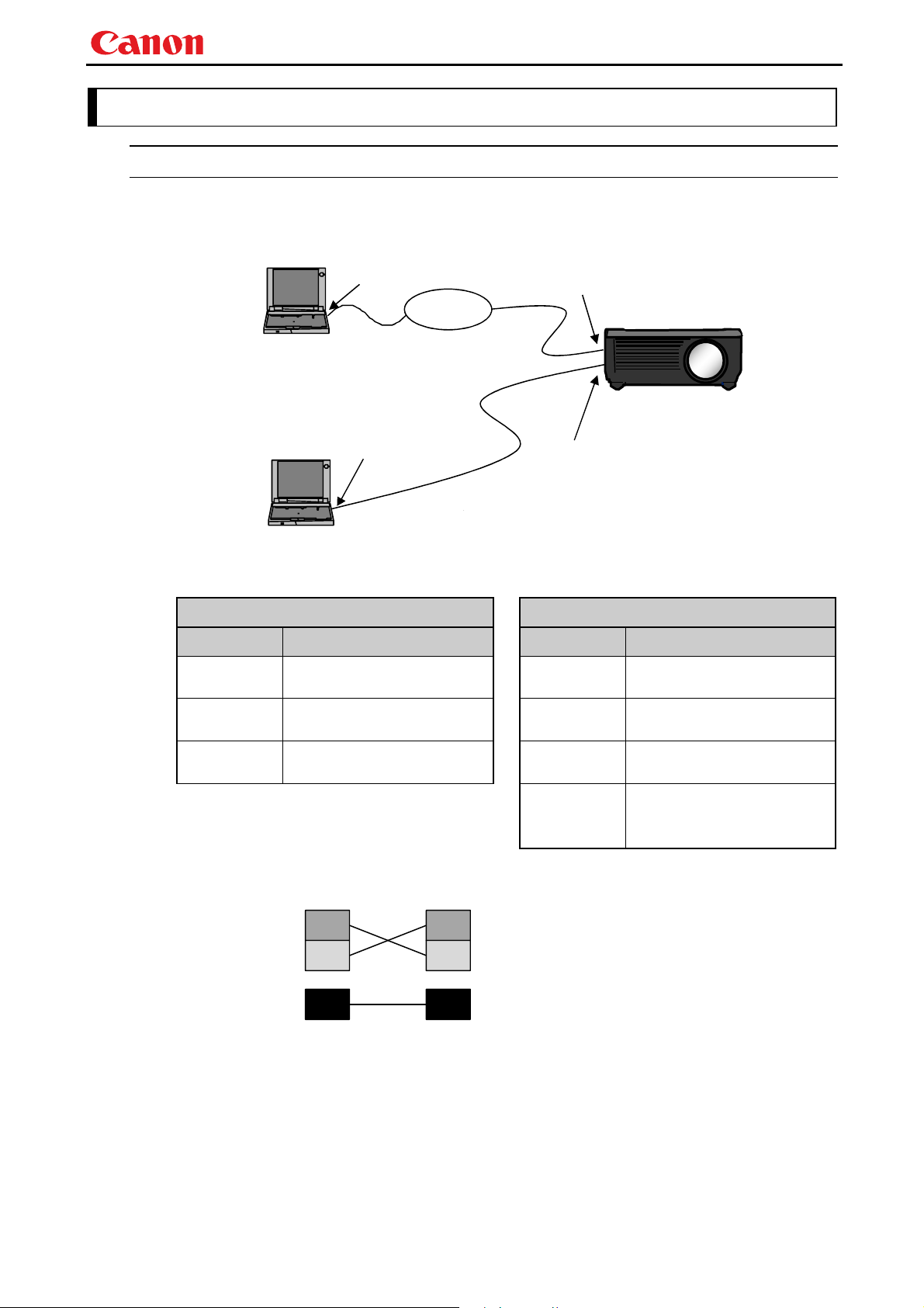
The projector can be controlled via RS-232C or LAN connection.
PC - Projector connection configuration
PC
PC
RS-232C connection
LAN PORT
Network Connection
COM PORT
ネットワーク接続
RS-232C
RS-232C
crossover cable
クロスケーブル
LAN PORT
SER VICE
PORT
プロジェクター
PROJECTO
LAN connection
Item Specifications
Connection
system
Connection
signal line
Connection
cable
Send Data
Receive Data
受信データ
Signal Ground
信号用設置 信号用設置
* Signal lines other than the three SD, RD, and SG lines are not used in the projector.
* Loop back its own signals on the PC side as necessary.
PC and projector connected on
a "1:1" basis
3-line connection of SD,
RD, and SG
9-pin RS-232C Cable (Cross)
SD SD
RD RD
SG SG
Send Data
送信データ送信データ
Receive Data
受信データ
Signal Ground
Item Specifications
Connection
system
Connection
signal line
Connection
cable
LAN
TCP / IP Connection
Straight when connecting via
network
LAN Cable
1000BASE-T
100BASE-TX
10BASE-T
- 2 -
Page 6
WUX450 / WX520 / WUX400ST / WX450ST User Commands
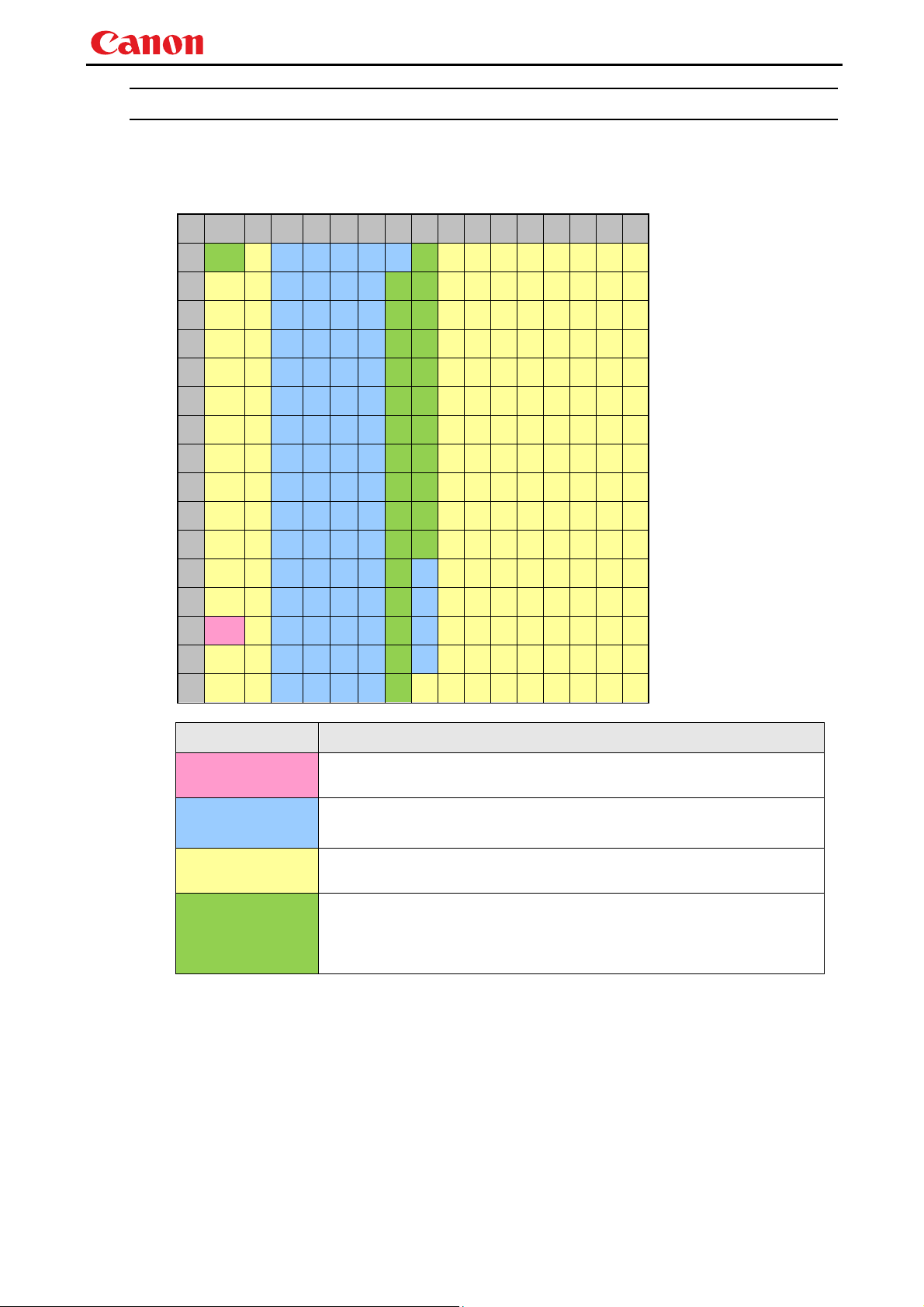
Usable Character Codes
Use ASCII codes in the red and blue areas of below table.
No distinction is made between double-byte characters and single-byte characters. Do not use
double-byte or triple-byte characters. They will all be recognized as single-byte characters.
Uppercase and lowercase alphabet letters are recognized as the same character.
0 1 2 3 4 5 6 7 8 9 A B C D E F
0 NUL SP 0 @ P ` p
1 ! 1 A Q a q
2 " 2 B R b r
3 # 3 C S c s
4 $ 4 D T d t
5 % 5 E U e u
6 & 6 F V f v
7 ' 7 G W g w
8 ( 8 H X h x
9 ) 9 I Y i y
A LF * : J Z j z
B + ; K [ k {
C , < L ¥ l |
D CR - = M ] m }
E . > N ^ n ~
F / ? O _ o
Item Specifications
Delimiters
General Characters
Invalid Characters
Unrecommeded
characters
CR(0Dh) 7Bh ~ 7Eh
Characters usable as delimiters.
20h to 60Eh 7Bh to 7Eh
Characters usable in commands.
Do not use the codes in regions other than the red and blue areas.
If used, it will be processed in the same way as space (20h).
Do not use as general rule.
Both upper case and lower case letters can be used in commands, but upper
case should be used in most cases.
- 3 -
Page 7

WUX450 / WX520 / WUX400ST / WX450ST User Commands
Communication System (Serial)
Item Specifications
Communication system RS-232-C Start-stop synchronization Semi-duplex communication
Transmission speed 19.2 Kbps
Character length 8 bits / character
Stop bit 2 bits
Parity None
Command format Variable-length records with terminals as delimiters
Maximum transmission
length
Delimiters
Command code
Communication
procedure
Flow control None
Error control None
Break signal Not supported
Timeout
* For timeout, see "Communication flow" on page 8.
Maximum of 256 characters (bytes) including delimiters.
CR (0Dh) can be used as delimiter.
Delimiter in the response is CR.
ASCII codes (20h to 7Eh)
Anything other than the above code and delimiter codes are processed in the
same way as space (20h).
No procedure
Tc Between characters: 1s
Tr
Communication System (LAN)
Item Specifications
Communication system Uses the TCP / IP protocol. Port: 33336
Between command / response
interval:
15s
Command Format
Commands are sent from PC to the projector in the following format:
<command text>
<value> Character strings consisting of 1 or more alphanumeric letters
<delimiter> CR(0Dh)
For <command strings> and <value>, see explanation about each command.
Example) When checking the power status (POWER)
PC to PJ
47h 45h 54h 3Dh 50h 4Fh 57h 45h 52h 0Dh
Format
<command text><delimiter> or
<command text>=(value>(delimiter>
Character strings consisting of 1 or more alphanumeric letters
G E T = P O W E R CR
- 4 -
Page 8
WUX450 / WX520 / WUX400ST / WX450ST User Commands
Response Format
Responses are sent from the projector to PC in the following format:
<Response character string> <Delimiter>
There are multiple response types, each having different <response string> format.
<Response character
string>
<Delimiter> CR(0Dh)
Format varies according to the type, as follows:
Strings consisting of 1 or more alphanumeric letters
First 2 digits are always 1 lowercase alphabet letter and a ":" (colon)
The first character indicates the response type.
Response
type
i Normal response i:OK
g Reference command
e Error response e:0002 INVALID_COMMAND
Meaning Example
g:BRI=0
response
Normal response
A response when command is processed normally.
The projector receives the next command only after receiving this response.
Format)
i:OK<delimiter>
Example)
PC to PJ
P O W E R = O N CR
50h 4Fh 57h 45h 52h 3Dh 4Fh 4Eh 0Dh
PJ to PC
i : O K CR
69h 3Ah 4Fh 4Bh 0Dh
- 5 -
Page 9

WUX450 / WX520 / WUX400ST / WX450ST User Commands
Reference command response
A response when reference is made properly for a reference command.
Format)
g:<command string>=<value><delimiter>
<command string> Character strings consisting of 1 or more alphanumeric letters
<value> Character strings consisting of 1 or more alphanumeric letters
Example)
PC to PJ
G E T = P O W E R CR
47h 45h 54h 3Dh 50h 4Fh 57h 45h 52h 0Dh
PJ to PC
g : P O W E R = O N CR
67h 3Ah 50H 4Fh 57h 45h 52h 3Dh 4Fh 4Eh 0Dh
Error response
A response when an error occurred.
Format)
e:<error ID><space><error info string>
<error ID> 4 alphanumeric letters
<space> Space character (20h)
<error info
string>
* Refer to “Error List”
Example)
PC to PJ
U T O P C CR
A
41h 55h 54h 4Fh 50h 43h 0Dh
PJ to PC
e : 2 0 1 F I N V A L I D _
65h 3Ah 32h 30h 31h 46h 20h 49h 4Eh 56h 41h 4Ch 49h 44h 5Fh
S I G N A L CR
53h 49h 47h 4Eh 41h 4Ch 0Dh
Character strings consisting of 1 or more
alphanumeric letters
- 6 -
Page 10

WUX450 / WX520 / WUX400ST / WX450ST User Commands
Normal response (BUSY)
This response is sent when a command cannot be received during processing.
Format)
i:BUSY<delimiter>
Example)
PC to PJ
A U T O P C CR
41h 55h 54h 4Fh 50h 43h 0Dh
PJ to PC
i : B U S Y CR
69h 3Ah 42h 55h 53h 59h 0Dh
Other
Command recognition
The receiver (projector) retains incoming characters within a specific Tc, and recognizes the data as
"received command" when delimiter is received.
If the character interval received exceeds the Tc or if a delimiter is not received within 256 characters,
all data already received is lost, and the mode is reset to standby to receive commands again.
Parameter value
Definition of <Parameter value> is as follows:
<Parameter value> <value 1>, <value 2>…,<value n>
<value n> <Numerical value> | <ID> | “<Character string>”
[<sign>]<decimal numeric string >
<numerical value>
<ID> 1 or more ASCII characters (20h to 60h, 7Bh to 7Eh)
<character string> 0 or more ASCII characters (20h to 60h, 7Bh to 7Eh)
The decimal string consists of minimum 1 letter and maximum 5
letters.
Valid value range is -32768 to 32767.
- 7 -
Page 11
WUX450 / WX520 / WUX400ST / WX450ST User Commands
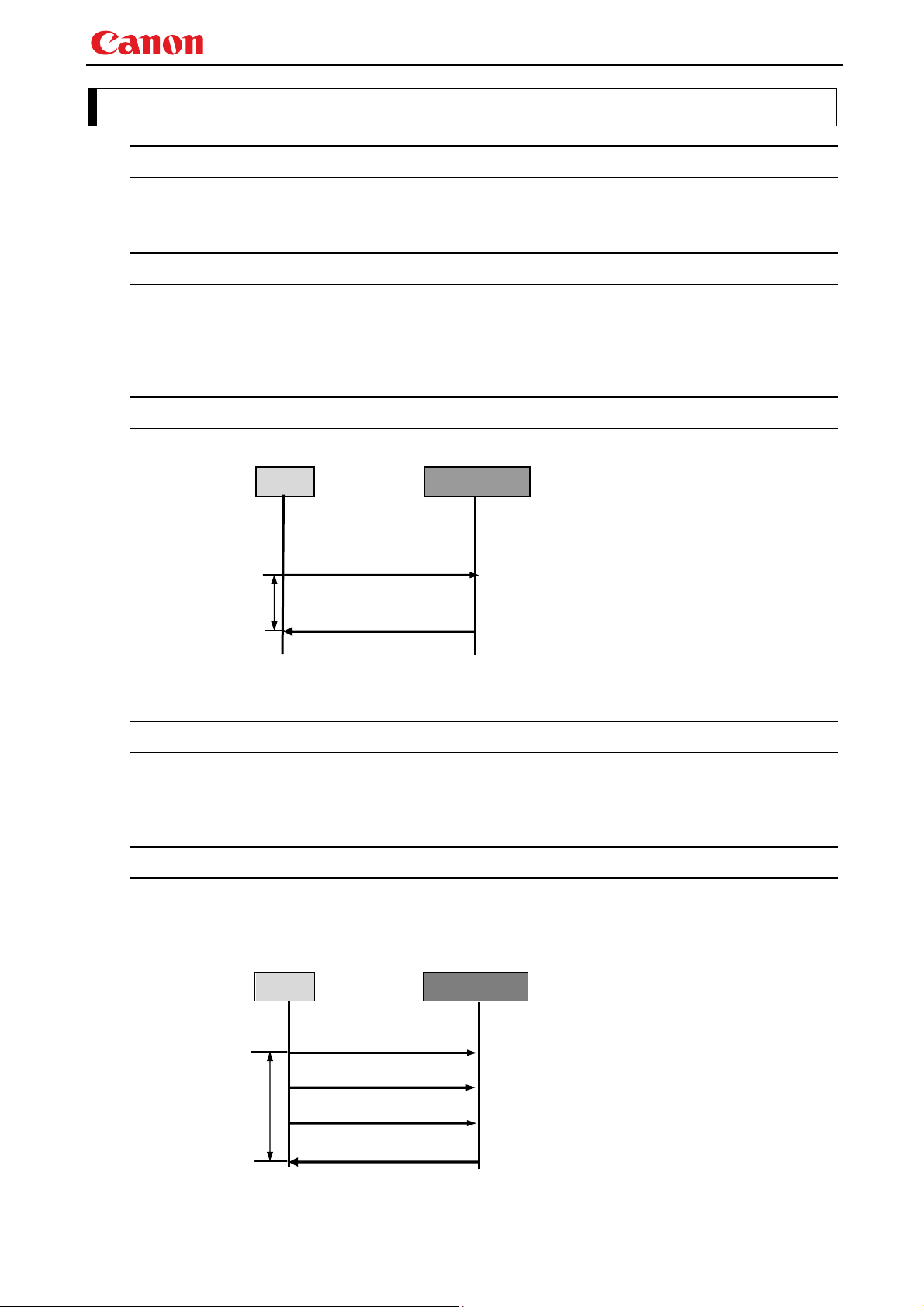
3. Communication Flow
Command Transmission (PC side)
Commands should be sent from PC in a way that each character is sent within the specified Tc
(inter-character timeout)
Command Reception (projector side)
The receiver (projector) retains incoming characters within a specific Tc, and recognizes the data as
"received command" when delimiter is received.
If the character interval received exceeds the Tc or if a delimiter is not received within 256 characters,
all data already received is lost, and the mode is reset to standby to receive commands again.
Command / Response
One response is always returned for each command sent from the PC.
PC
Projector
WithinTr
* The timeout interval between command and response (Tr) is 15 seconds.
Commands
Response
Response Reception Timeout
If a response is not received within the Tr (timeout interval between command and response) while
standing by a waiting response after sending a command from the PC, it is deemed to have exceeded
the “response reception timeout.” Please resend the command.
Other
The projector can be communicated as long as it is supplied with AC power, even in standby mode.
The PC side cannot send the next user command before a response for the first command is returned.
If 2 or more user commands are received in a single port, user commands from 2nd one are discarded.
If 2 or more user commands are received in a single port, only 1st command is processed, and a
response is returned when finished.
PC
Projector
WithinTr
Note: Timeout (Tr) between a command and a response is 15 seconds.
Command 1
Command 2
Command 3
Response to Command 1
Process executed
Discarded
Discarded
- 8 -
Page 12
WUX450 / WX520 / WUX400ST / WX450ST User Commands
4. Command List
Item Commands Setting Reference Description
1
2
3
4
5
6
7
6AXADJ
6AXR
6AXG
6AXB
6AXC
6AXM
6AXY
Yes Yes
Yes Yes
Yes Yes
Yes Yes
Yes Yes
Yes
Yes
Yes
Yes
6-axis adjustment ON/OFF
6-axix correction R Hue / Saturation /
Brightness
6-axix correction G Hue / Saturation /
Brightness
6-axix correction B Hue / Saturation /
Brightness
6-axix correction C Hue / Saturation /
Brightness
6-axix correction M Hue / Saturation /
Brightness
6-axix correction Y Hue / Saturation /
Brightness
Power mode restriction
SL1 SL3 ST ON
- - -
- - -
- - -
- - -
- - -
- - -
- - -
Yes
Yes
Yes
Yes
Yes
Yes
Yes
8
AMBADJ
9
AMBLEVEL
10
AMBTYPE
11
ASELA1
12
ASELA2
13
ASELC
14
ASELD
15
ASELH
16
ASPECT
17
AUTOPC
18
AUTOSETEXE
19
AVOL
20
BLANK
21
BRI
22
COLOR_TEMP
23
COMVER
24
CONT
25
DGAMMA
26
DZOOM_POS
27
DZOOM_RAT
28
ERR
29
FINE_GAMMA_B
30
FINE_GAMMA_G
31
FINE_GAMMA_R
32
FLTWRN
33
FREEZE
34
GAMMA
35
HDMI_IN
Yes Yes
Yes Yes
Yes Yes
Yes Yes
Yes Yes
Yes Yes
Yes Yes
Yes Yes
Yes Yes
Yes
Yes
-
-
Yes Yes
Yes Yes
Yes Yes
Yes Yes
-
Yes
Yes Yes
Yes Yes
Yes Yes
Yes Yes
-
Yes
Yes Yes
Yes Yes
Yes Yes
Yes Yes
Yes Yes
Yes Yes
Yes Yes
Ambient light correction adjustment ON/OFF
Ambient light level settings
Ambient light type settings
Analog PC-1 audio terminal selection
Analog PC-2 audio terminal selection
Component audio terminal selection
Digital PC audio terminal selection
HDMI audio terminal selection
Screen settings
Auto PC
Auto setup
Audio volume adjustment
BLANK function
Brightness setting
Color temperature setting
User command version inquiry
Contrast setting
Dynamic gamma
DZOOM position setting
DZOOM ratio setting
Error information inquiry
Fine gamma (B) adjustment
Fine gamma (G) adjustment
Fine gamma (R) adjustment
Filter warning indication at startup
Freeze status
Gamma adjustment
HDMI input setting
- - -
- - -
- - -
- - -
- - -
- - -
- - -
- - -
- - -
- - -
- - -
- - -
- - -
- - -
- - -
Yes
Yes
Yes
Yes
Yes
Yes
Yes
Yes
Yes
Yes
Yes
Yes
Yes
Yes
Yes
Yes Yes Ye s Yes
- - -
- - -
- - -
- - -
Yes
Yes
Yes
Yes
Yes Yes Ye s Yes
- - -
- - -
- - -
- - -
- - -
- - -
- - -
Yes
Yes
Yes
Yes
Yes
Yes
Yes
- 9 -
Page 13
WUX450 / WX520 / WUX400ST / WX450ST User Commands
Item Commands Setting Reference Description
36
HDMI_OVSCAN
37
HUE
38
IMAGE
39
IMAGEFLIP
40
INPUT
41
KREP
42
LAMP
43
LAMPCOUNTER
44
LMPWRN
45
MAIN
46
MEMF
47
MEMS
48
MEMG
49
MUTE
50
NR
51
POWER
Yes Yes
Yes Yes
Yes Yes
Yes Yes
Yes Yes
Yes Yes
Yes Yes
-
Yes
Yes Yes
Yes
-
Yes Yes
Yes Yes
Yes Yes
Yes Yes
Yes Yes
Yes Yes
HDMI overscan setting
Hue setting
Image mode setting
Flip display
Input selection
Key repeat
Lamp output setting
Lamp ON time inquiry
Lamp warning indication at startup
Side control operation emulation
Memory color adjustment (flesh)
Memory color adjustment (sky)
Memory color adjustment (green)
Mute control
Noise reduction
This controls the power supply
Power mode restriction
SL1 SL3 ST ON
- - -
- - -
- - -
- - -
- - -
- - -
- - -
Yes
Yes
Yes
Yes
Yes
Yes
Yes
Yes Yes Ye s Yes
- - -
Yes
Yes Yes Ye s Yes
- - -
- - -
- - -
- - -
- - -
Yes
Yes
Yes
Yes
Yes
Yes Yes Ye s Yes
52
PRODCODE
53
RC
54
RGBGAIN
55
RGBOFFSET
56
ROMVER
57
SAT
58
SAVEIMGPROF
59
SCRNASPECT
60
SHARP
61
SIGNAL_INFO
62
SIGNALSTATUS
63
TEMP
64
TPTN
Note: About "Power mode restriction"
Commands are executable only when the projector is in the mode indicated by "○." Meaning of each mode is
as follows:
SL1: Standby mode when "Network standby setting" is set to "Eco" (for commands sent through LAN)
SL3: Standby mode when "Network standby setting" is set to "Normal" (for commands sent through LAN)
ST: Standby mode (for all commands sent via RS-232C, regardless of the network setting)
ON: Power on status
-
Yes
Yes Yes
Yes Yes
-
Yes Yes
Yes Yes
Yes Yes
Yes Yes
-
-
-
Yes Yes
Yes
Yes
Yes
Yes
Yes
Product information inquiry
Remote control operation emulate
-
RGB gain adjustment
RGB offset adjustment
ROM version inquiry
Color saturation setting
Create user memory
Screen aspect setting
Sharpness setting
Input signal information inquiry
Signal status inquiry
Temperature sensor value inquiry
Test pattern
Yes Yes Ye s Yes
Yes Yes Ye s Yes
- - -
- - -
Yes Yes Ye s Yes
- - -
- - -
- - -
- - -
- - -
- - -
- - -
- - -
Yes
Yes
Yes
Yes
Yes
Yes
Yes
Yes
Yes
Yes
- 10 -
Page 14

WUX450 / WX520 / WUX400ST / WX450ST User Commands
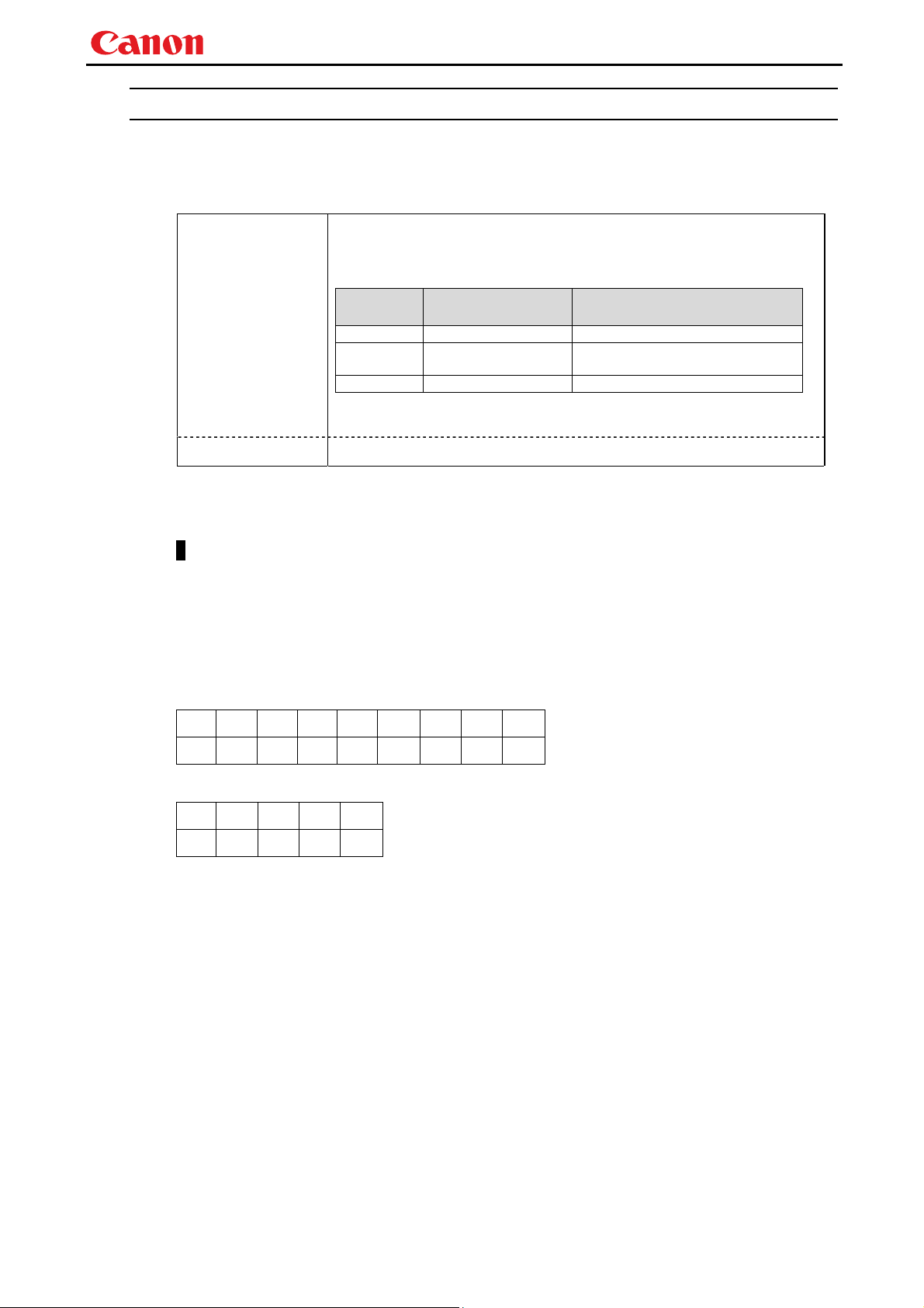
5. Guide to command description
This section explains how commands are described.
The command descriptions have the format shown below.
EXAMPLE
Summary of the function
Format
Setting Command A command format when a command is sent to the projector to make a setting
for the function.
"-" is shown when there is no setting command.
Example) 6AXADJ=<6-axix adjustment parameter: ID>
Response A response format for the setting command.
"-" is shown when there is no setting command.
Example) i:OK
Reference Command A command format when a command is sent to the projector to refer to the
current setting, status and others for the function.
"-" is shown when there is no reference command.
Example) GET=6AXADJ
Response A response format for a reference command.
"-" is shown when there is no reference command.
Example) g:6AXADJ=<6-axis adjustment parameter: ID>
Note: See "Error list" for any response other than the above.
When parameters exist for the command, a list of parameter is inserted in this position.
Example)
<6-axis adjustment parameter: ID>
Parameter Meaning
ON Valid
OFF Invalid
- 11 -
Page 15

WUX450 / WX520 / WUX400ST / WX450ST User Commands
Environment
This defines the environments that support the command (power supply state, input signal state).
The command is executable when the projector is in the mode indicated by "○" in the table of
corresponding command description page.
Power mode restriction
LAN *1 RS-232C *6
SL0 SL1 SL3 ON ST ON D-RGB A-RGB COMP HDMI LAN USB None
*2 *3 *4 *5 *7 *5 *8 *8 *8 *8 *8 *8 *8
*1 Power mode restriction/LAN Indicates whether the command coming through LAN is executable.
*2 SL0 Standby mode, and the network function is turned off.
When the network function is turned off, the command is not executable if
coming from LAN, in which case, this should never be “O”.
*3 SL1 "O" if enabled in a power ON state.
*4 SL3 Standby mode, and the network standby setting is set to "Eco."
*5 ON Normal projection status
*6 Power / RS-232C Indicates whether the command coming through RS-232C is executable.
*7 ST Standby mode (includes SL0, SL1 and SL3 altogether, regardless of the
network setting).
*8 Input Indicates whether the command that is depending on input signal is
executable while the power is on.
Input *8
Remarks
Remarks about the command is inserted when necessary.
Example
Specific example of the command is inserted when necessary.
- 12 -
Page 16
6. Command Details
6AXADJ
6-axix adjustment / OFF
Format
Setting Command 6AXADJ=<6-axix adjustment parameter: ID>
Reference Command GET=6AXADJ
<6-axis adjustment parameter:ID>
OFF Turned off
ON Adjusted
Environment
Power mode restriction
SL0 SL1 SL3 ON ST ON D-RGB A-RGB COMP HDMI LAN USB None
No No No Yes N o Ye s Yes Ye s Yes Yes Ye s Yes Ye s
Remarks
(1) Use "6AXR - Y" command when this is set to "ON" and the corrected 6-axis values need to be
changed.
(2) This sets the currently selected input signal and image mode.
WUX450 / WX520 / WUX400ST / WX450ST User Commands
Response i:OK
Response g:6AXADJ=<6-axix adjustment parameter: ID>
Note: See "Error list" for any response other than the above.
Parameter Meaning
Input
LAN RS-232C
- 13 -
Page 17

WUX450 / WX520 / WUX400ST / WX450ST User Commands
6AXR
6-axis adjustment (red), hue/saturation/brightness
Format
Setting Command 6AXR=<R hue:Number>,<R saturation:Number>,
<R brightness:Number>
Response i:OK
Reference Command GET=6AXR
Response g:6AXR=<R hue:Number>,<R saturation:Number>,
<R brightness:Number>
Note: See "Error list" for any response other than the above.
<R hue:Number> is within -20 to 20
<R saturation:Number> is within -20 to 20
<R brightness:Number> is within -20 to 20
Environment
Power mode restriction
LAN RS-232C
SL0 SL1 SL3 ON ST ON D-RGB A-RGB COMP HDMI LAN USB None
No No No Yes N o Ye s Yes Ye s Yes Yes Ye s Yes Ye s
Input
Remarks
(1) When 6-axix adjustment is turned on, these settings are shown over the displayed image.
However, the settings can be changed regardless of whether 6-axis adjustment is turned on or
not.
(2) This sets the currently selected input signal and image mode.
- 14 -
Page 18

WUX450 / WX520 / WUX400ST / WX450ST User Commands
6AXG
6-axis adjustment (green), hue/saturation/brightness
Format
Setting Command 6AXG=<G hue:Number>,<G saturation:Number>,
<G brightness:Number>
Response i:OK
Reference Command GET=6AXG
Response g:6AXG=<G hue:Number>,<G saturation:Number>,
<G brightness:Number>
Note: See "Error list" for any response other than the above.
<G hue:Number> is within -20 to 20
<G saturation:Number> is within -20 to 20
<G brightness:Number> is within -20 to 20
Environment
Power mode restriction
LAN RS-232C
SL0 SL1 SL3 ON ST ON D-RGB A-RGB COMP HDMI LAN USB None
No No No Yes N o Ye s Yes Ye s Yes Yes Ye s Yes Ye s
Input
Remarks
(1) When 6-axix adjustment is turned on, these settings are shown over the displayed image.
However, the settings can be changed regardless of whether 6-axis adjustment is turned on or
not.
(2) This sets the currently selected input signal and image mode.
- 15 -
Page 19

WUX450 / WX520 / WUX400ST / WX450ST User Commands
6AXB
6-axis adjustment (blue), hue/saturation/brightness
Format
Setting Command 6AXB=<B hue:Number>,<B saturation:Number>,
<B brightness:Number>
Response i:OK
Reference Command GET=6AXB
Response g:6AXB=<B hue:Number>,<B saturation:Number>,
<B brightness:Number>
Note: See "Error list" for any response other than the above.
<B hue:Number> is within -20 to 20
<B saturation:Number> is within -20 to 20
<B brightness:Number> is within -20 to 20
Environment
Power mode restriction
LAN RS-232C
SL0 SL1 SL3 ON ST ON D-RGB A-RGB COMP HDMI LAN USB None
No No No Yes N o Ye s Yes Ye s Yes Yes Ye s Yes Ye s
Input
Remarks
(1) When 6-axix adjustment is turned on, these settings are shown over the displayed image.
However, the settings can be changed regardless of whether 6-axis adjustment is turned on or
not.
(2) This sets the currently selected input signal and image mode.
- 16 -
Page 20

WUX450 / WX520 / WUX400ST / WX450ST User Commands
6AXC
6-axis adjustment (cyan), hue/saturation/brightness
Format
Setting Command 6AXC=<C hue:Number>,<C saturation:Number>,
<C brightness:Number>
Response i:OK
Reference Command GET=6AXC
Response g:6AXC=<C hue:Number>,<C saturation:Number>,
<C brightness:Number>
Note: See "Error list" for any response other than the above.
<C hue:Number> is within -20 to 20
<C saturation:Number> is within -20 to 20
<C brightness:Number> is within -20 to 20
Environment
Power mode restriction
LAN RS-232C
SL0 SL1 SL3 ON ST ON D-RGB A-RGB COMP HDMI LAN USB None
No No No Yes N o Ye s Yes Ye s Yes Yes Ye s Yes Ye s
Input
Remarks
(1) When 6-axix adjustment is turned on, these settings are shown over the displayed image.
However, the settings can be changed regardless of whether 6-axis adjustment is turned on or
not.
(2) This sets the currently selected input signal and image mode.
- 17 -
Page 21

WUX450 / WX520 / WUX400ST / WX450ST User Commands
6AXM
6-axis adjustment (magenta), hue/saturation/brightness
Format
Setting Command 6AXM=<M hue:Number>,<M saturation:Number>,
<M brightness:Number>
Response i:OK
Reference Command GET=6AXM
Response g:6AXC=<M hue:Number>,<M saturation:Number>,
<M brightness:Number>
Note: See "Error list" for any response other than the above.
<M hue:Number> is within -20 to 20
<M saturation:Number> is within -20 to 20
<M brightness:Number> is within -20 to 20
Environment
Power mode restriction
LAN RS-232C
SL0 SL1 SL3 ON ST ON D-RGB A-RGB COMP HDMI LAN USB None
No No No Yes N o Ye s Yes Ye s Yes Yes Ye s Yes Ye s
Input
Remarks
(1) When 6-axix adjustment is turned on, these settings are shown over the displayed image.
However, the settings can be changed regardless of whether 6-axis adjustment is turned on or
not.
(2) This sets the currently selected input signal and image mode.
- 18 -
Page 22

WUX450 / WX520 / WUX400ST / WX450ST User Commands
6AXY
6-axis adjustment (yellow), hue/saturation/brightness
Format
Setting Command 6AXY=<Y hue:Number>,<Y saturation:Number>,
<Y brightness:Number>
Response i:OK
Reference Command GET=6AXY
Response g:6AXY=<Y hue:Number>,<Y saturation:Number>,
<Y brightness:Number>
Note: See "Error list" for any response other than the above.
<Y hue:Number> is within -20 to 20
<Y saturation:Number> is within -20 to 20
<Y brightness:Number> is within -20 to 20
Environment
Power mode restriction
LAN RS-232C
SL0 SL1 SL3 ON ST ON D-RGB A-RGB COMP HDMI LAN USB None
No No No Yes N o Ye s Yes Ye s Yes Yes Ye s Yes Ye s
Remarks
(1) When 6-axix adjustment is turned on, these settings are shown over the displayed image.
However, the settings can be changed regardless of whether 6-axis adjustment is turned on or
not.
(2) This sets the currently selected input signal and image mode.
Input
- 19 -
Page 23

WUX450 / WX520 / WUX400ST / WX450ST User Commands
AMBADJ
Ambient light adjustment / OFF
Format
Setting Command AMBADJ=<Ambient light correction adjustment parameter:ID>
Response i:OK
Reference Command GET=AMBADJ
Response g:AMBADJ=<Ambient light correction adjustment parameter:ID>
Note: See "Error list" for any response other than the above.
< Ambient light correction adjustment parameter:ID >
Parameter Meaning
OFF Turned off
ON Adjusted
Environment
Power mode restriction
LAN RS-232C
SL0 SL1 SL3 ON ST ON D-RGB A-RGB COMP HDMI LAN USB None
No No No Yes N o Ye s Yes Ye s Yes Yes Ye s Yes Ye s
Remarks
(1) "Ambient light level" and "Ambient light type" settings take effect on the displayed image
when "Ambient light correction" is activated.
To adjust the "Ambient light level" or "Ambient light type", use "AMB_LEVEL" or
"AMB_TYPE" command, respectively.
(2) This sets the currently selected input signal and image mode.
Input
AMBLEVEL
Ambient light level settings
Format
Setting Command AMBLEVEL=<Ambient light level settings parameter:ID>
Response i:OK
Reference Command GET=AMBLEVEL
Response g:AMBLEVEL=<Ambient light level settings parameter:ID>
Note: See "Error list" for any response other than the above.
< Ambient light level settings parameter:ID >
Parameter Meaning
OFF Weak
ON Strong
Environment
Power mode restriction
LAN RS-232C
SL0 SL1 SL3 ON ST ON D-RGB A-RGB COMP HDMI LAN USB None
No No No Yes N o Ye s Yes Ye s Yes Yes Ye s Yes Ye s
Remarks
(1) This sets the currently selected input signal and image mode.
Input
- 20 -
Page 24

WUX450 / WX520 / WUX400ST / WX450ST User Commands
AMBTYPE
Ambient light type setting
Format
Setting Command AMBTYPE=<Ambient light type settings parameter:ID>
Response i:OK
Reference Command GET=AMBTYPE
Response g:AMBTYPE=<Ambient light type settings parameter:ID>
Note: See "Error list" for any response other than the above.
< Ambient light type settings parameter:ID >
Parameter Meaning
TG Tungsten lamp
FL Fluorescent lamp
Environment
Power mode restriction
LAN RS-232C
SL0 SL1 SL3 ON ST ON D-RGB A-RGB COMP HDMI LAN USB None
No No No Yes N o Ye s Yes Ye s Yes Yes Ye s Yes Ye s
Remarks
(1) This sets the currently selected input signal and image mode.
Input
ASELA1
Analog PC-1 audio terminal selection
Format
Setting Command ASELA1=<Analog PC-1 audio terminal selection: ID>
Response i:OK
Reference Command GET=ASELA1
Response g:ASELA1=<Analog PC-1 audio terminal selection: ID>
Note: See "Error list" for any response other than the above.
< Analog PC-1 audio terminal selection: ID >
Parameter Meaning
1 Audio In 1
2 Audio In 2
OFF Turned off
Environment
Power mode restriction
LAN RS-232C
SL0 SL1 SL3 ON ST ON D-RGB A-RGB COMP HDMI LAN USB None
No No No Yes N o Ye s Yes Ye s Yes Yes Ye s Yes Ye s
Input
- 21 -
Page 25

WUX450 / WX520 / WUX400ST / WX450ST User Commands
ASELA2
Analog PC-2 Audio input terminal selection
Format
Setting Command ASELA2=<Analog PC-2 audio terminal selection parameter: ID>
Response i:OK
Reference Command GET=ASELA2
Response g:ASELA2=<Analog PC-2 audio terminal selection parameter: ID>
Note: See "Error list" for any response other than the above.
< Analog PC-2 audio terminal selection parameter: ID >
Parameter Meaning
1 Audio In 1
2 Audio In 2
OFF Turned off
Environment
Power mode restriction
LAN RS-232C
SL0 SL1 SL3 ON ST ON D-RGB A-RGB COMP HDMI LAN USB None
No No No Yes N o Ye s Yes Ye s Yes Yes Ye s Yes Ye s
Input
ASELC
Component Audio input terminal selection
Format
Setting Command ASELC=<Component audio terminal selection parameter: ID>
Response i:OK
Reference Command GET=ASELC
Response g:ASELC=<Component audio terminal selection parameter: ID>
Note: See "Error list" for any response other than the above.
< Component audio terminal selection parameter: ID >
Parameter Meaning
1 Audio In 1
2 Audio In 2
OFF Turned off
Environment
Power mode restriction
LAN RS-232C
SL0 SL1 SL3 ON ST ON D-RGB A-RGB COMP HDMI LAN USB None
No No No Yes N o Ye s Yes Ye s Yes Yes Ye s Yes Ye s
Input
- 22 -
Page 26

WUX450 / WX520 / WUX400ST / WX450ST User Commands
ASELD
Digital PC Audio input terminal selection
Format
Setting Command ASELD=<Digital PC audio terminal selection parameter: ID>
Response i:OK
Reference Command GET=ASELD
Response g:ASELD=<Digital PC audio terminal selection parameter: ID>
Note: See "Error list" for any response other than the above.
< Digital PC audio terminal selection parameter: ID >
Parameter Meaning
1 Audio In 1
2 Audio In 2
OFF Turned off
Environment
Power mode restriction
LAN RS-232C
SL0 SL1 SL3 ON ST ON D-RGB A-RGB COMP HDMI LAN USB None
No No No Yes N o Ye s Yes Ye s Yes Yes Ye s Yes Ye s
Input
ASELH
HDMI Audio input terminal selection
Format
Setting Command ASELH=<HDMI audio terminal selection parameter: ID>
Response i:OK
Reference Command GET=ASELH
Response g:ASELH=<HDMI audio terminal selection parameter: ID>
Note: See "Error list" for any response other than the above.
< HDMI audio terminal selection parameter: ID >
Parameter Meaning
H HDMI audio
1 Audio In 1
2 Audio In 2
OFF Turned off
Environment
Power mode restriction
LAN RS-232C
SL0 SL1 SL3 ON ST ON D-RGB A-RGB COMP HDMI LAN USB None
No No No Yes N o Ye s Yes Ye s Yes Yes Ye s Yes Ye s
Input
- 23 -
Page 27

WUX450 / WX520 / WUX400ST / WX450ST User Commands
ASPECT
Aspect ratio
Format
Setting Command ASPECT=<Screen setting parameters: ID>
Response i:OK
Reference Command GET=ASPECT
Response g:ASPECT=<Screen setting parameters: ID>
Note: See "Error list" for any response other than the above.
< Screen setting parameters:ID >
Parameter Meaning
AUTO Auto
4:3 4:3
16:9 16:9
16:10 16:10
ZOOM Zoom
TRUE Real
Environment
Power mode restriction
LAN RS-232C
SL0 SL1 SL3 ON ST ON D-RGB A-RGB COMP HDMI LAN USB None
No No No Yes N o Ye s Yes Ye s Yes Yes Ye s Yes Ye s
Remarks
(1) Aspect setting may be automatically changed by other setting when the input terminal is
changed or input signal is disturbed.
Input
AUTOPC
Auto PC
Format
Setting Command AUTOPC
Response i:OK
Reference Command -
Response -
Note: See "Error list" for any response other than the above.
Environment
Power mode restriction
LAN RS-232C
SL0 SL1 SL3 ON ST ON D-RGB A-RGB COMP HDMI LAN USB None
No No No Yes No Yes No Yes No No No No No
Remarks
(1) Execution of this command may modify the following setting values.
・Total number of dots
・Tracki ng
・Horizontal / vertical positions
・Number of horizontal / vertical display dots
Input
- 24 -
Page 28

WUX450 / WX520 / WUX400ST / WX450ST User Commands
AUTOSETEXE
Auto setup
Format
Setting Command AUTOSETEXE=<Auto set parameter:ID>
Response i:OK
Reference Command -
Response -
Note: See "Error list" for any response other than the above.
< Auto set parameter:ID >
Parameter Meaning
INPUT Runs auto input
Environment
Power mode restriction
LAN RS-232C
SL0 SL1 SL3 ON ST ON D-RGB A-RGB COMP HDMI LAN USB None
No No No Yes N o Ye s Yes Ye s Yes Yes Ye s Yes Ye s
Input
AVOL
Audio volume adjustment
Format
Setting Command AVOL=<Audio volume:Number>
Response i:OK
Reference Command GET=AVOL
Response g:AVOL=<Audio volume:Number>
Note: See "Error list" for any response other than the above.
Setting values for <Audio volume:Number> are 0 to 20.
Environment
Power mode restriction
LAN RS-232C
SL0 SL1 SL3 ON ST ON D-RGB A-RGB COMP HDMI LAN USB None
No No No Yes N o Ye s Yes Ye s Yes Yes Ye s Yes Ye s
Remarks
(1) The volume level can be set even while the sound is muted.
Input
- 25 -
Page 29

WUX450 / WX520 / WUX400ST / WX450ST User Commands
BLANK
BLANK setting
Format
Setting Command BLANK=<BLANK parameter:ID>
Response i:OK
Reference Command GET=BLANK
Response g:BLANK=<BLANK parameter:ID>
Note: See "Error list" for any response other than the above.
< BLANK parameter:ID >
Parameter Meaning
ON BLANK ON
OFF BLANK OFF
Environment
Power mode restriction
LAN RS-232C
SL0 SL1 SL3 ON ST ON D-RGB A-RGB COMP HDMI LAN USB None
No No No Yes N o Ye s Yes Ye s Yes Yes Ye s Yes Ye s
Remarks
(1) Executing this command in a FREEZE status will cancel the FREEZE status and become
BLANK.
Input
BRI
Brightness
Format
Setting Command BRI=<Brightness setting:Number>
Response i:OK
Reference Command GET=BRI
Response g:BRI=<Brightness setting:Number>
Note: See "Error list" for any response other than the above.
Setting values for <Brightness setting:Number> are -20 to 20.
Environment
Power mode restriction
LAN RS-232C
SL0 SL1 SL3 ON ST ON D-RGB A-RGB COMP HDMI LAN USB None
X X X O X O O O O O O O O
Remarks
(1) This sets the currently selected input signal and image mode.
Input
- 26 -
Page 30

WUX450 / WX520 / WUX400ST / WX450ST User Commands
COLOR_TEMP
Color temperature
Format
Setting Command COLOR_TEMP=<Color temperature setting:Number>
Response i:OK
Reference Command GET=COLOR_TEMP
Response g:COLOR_TEMP=<Color temperature setting:Number>
Note: See "Error list" for any response other than the above.
Setting values for <Color temperature setting:Number> are -17 to 21.
Environment
Power mode restriction
LAN RS-232C
SL0 SL1 SL3 ON ST ON D-RGB A-RGB COMP HDMI LAN USB None
No No No Yes N o Ye s Yes Ye s Yes Yes Ye s Yes Ye s
Remarks
(1) This sets the currently selected input signal and image mode.
Input
COMVER
User command version reference
Format
Setting Command -
Response -
Reference Command GET=COMVER
Response g:COMVER="<User command version:Character string>
Note: See "Error list" for any response other than the above.
Environment
Power mode restriction
LAN RS-232C
SL0 SL1 SL3 ON ST ON D-RGB A-RGB COMP HDMI LAN USB None
No Yes Ye s Yes Yes Yes Ye s Yes Yes Ye s Yes Yes Yes
Remarks
(1) User command version consists of <2-digit number> and <4-digit number>.
(Example "01.1234")
Input
- 27 -
Page 31

WUX450 / WX520 / WUX400ST / WX450ST User Commands
CONT
Contrast
Format
Setting Command CONT=<Contrast setting:Number>
Response i:OK
Reference Command GET=CONT
Response g:COMVER="<User command version:Character string>
Note: See "Error list" for any response other than the above.
Setting values for <Contrast setting:Number> are -20 to 20.
Environment
Power mode restriction
LAN RS-232C
SL0 SL1 SL3 ON ST ON D-RGB A-RGB COMP HDMI LAN USB None
No No No Yes N o Ye s Yes Ye s Yes Yes Ye s Yes Ye s
Remarks
(1) This sets the currently selected input signal and image mode.
Input
DGAMMA
Dynamic gamma
Format
Setting Command DGAMMA=<Dynamic gamma setting parameter:ID>
Response i:OK
Reference Command GET=DGAMMA
Response g:DGAMMA=<Dynamic gamma setting parameter:ID>
Note: See "Error list" for any response other than the above.
< Dynamic gamma setting parameter:ID >
Parameter Meaning
OFF Off
WEAK Weak
MIDDLE Middle
STRONG Strong
Environment
Power mode restriction
LAN RS-232C
SL0 SL1 SL3 ON ST ON D-RGB A-RGB COMP HDMI LAN USB None
No No No Yes N o Ye s Yes Ye s Yes Yes Ye s Yes Ye s
Remarks
(1) This sets the currently selected input signal and image mode.
Input
- 28 -
Page 32

WUX450 / WX520 / WUX400ST / WX450ST User Commands
DZOOM_POS
DZOOM position setting
Format
Setting Command DZOOM_POS=<DZOOM position X:Number>,<DZOOM position Y:Number>
Response i:OK
Reference Command GET=DZOOM_POS
Response g:DZOOM_POS=<DZOOM position X:Number>,<DZOOM position Y:Number>
Note: See "Error list" for any response other than the above.
<DZOOM position X / Y:Number> is a signed integer indicating the central position of the enlarged input image.
Environment
Power mode restriction
LAN RS-232C
SL0 SL1 SL3 ON ST ON D-RGB A-RGB COMP HDMI LAN USB None
No No No Yes N o Ye s Yes Ye s Yes Yes Ye s Yes Ye s
Remarks
(1) This command is identical to pressing the arrow keys to move while DZOOM is enabled,
however, the position can be specified in more detail.
(2) If a position outside the range is specified, the position is automatically moved to the nearest
position within the range.
(3) 0 for <DZOOM position X / Y:Number> indicates the center position of the input image.
(4) Positive direction for <DZOOM position X / Y:Number> corresponds to RIGHT and UP keys,
and negative direction corresponds to LEFT and DOWN keys.
(5) The numerical value for <DZOOM position X / Y:Number> represents units in pixels of the
input image.
* For example, in a case where an input image of XGA (1024 x 768) size is enlarged twice the
size (range of 512 x 384 is displayed), up to ±256 for <DZOOM position X:Number>, and up to
±192 for <DZOOM position Y:Number> can be specified.
Input
- 29 -
Page 33

WUX450 / WX520 / WUX400ST / WX450ST User Commands
DZOOM_RAT
DZOOM ratio setting
Format
Setting Command DZOOM_RAT=<DZOOM ratio parameter:ID>
Response i:OK
Reference Command GET=DZOOM_RAT
Response g: DZOOM_RAT=<DZOOM ratio parameter:ID>
Note: See "Error list" for any response other than the above.
< DZOOM ratio parameter:ID >
Parameter Meaning
1 same size (DZOOM disabled)
1.5 1.5x
2 2x
3 3x
4 4x
5 5x
6 6x
8 8x
10 10x
12 12x
Environment
Power mode restriction
LAN RS-232C
SL0 SL1 SL3 ON ST ON D-RGB A-RGB COMP HDMI LAN USB None
No No No Yes N o Ye s Yes Ye s Yes Yes Ye s Yes Ye s
Remarks
(1) The SET command can be used when DZOOM is disabled and set to other than "1", to enable
DZOOM and display the ratio on the screen.
(2) The SET command can be used when DZOOM is enabled and set to "1", to disable DZOOM
and hide the ratio from the screen.
Input
- 30 -
Page 34

WUX450 / WX520 / WUX400ST / WX450ST User Commands
ERR
Error information reference
Format
Setting Command -
Response -
Reference Command GET=ERR
Response g:ERR=<ErrorID:Character string>
Note: See "Error list" for any response other than the above.
< DZOOM ratio parameter:ID >
Parameter Meaning
NO_ERROR No error
ABNORMAL_TEMPERATURE Temperature error
FAULTY_LAMP Lamp error
FAULTY_LAMP_COVER Lamp cover error
FAULTY_COOLING_FAN Cooling fan error
FAULTY_POWER_SUPPLY Power supply error
FAULTY_AIR_FILTER Air filter error
Environment
Power mode restriction
LAN RS-232C
SL0 SL1 SL3 ON ST ON D-RGB A-RGB COMP HDMI LAN USB None
No Yes Ye s Yes Yes Yes Ye s Yes Yes Ye s Yes Yes Yes
Remarks
(1) Information when the warning LED of the projector is flashing can be obtained. "NO_ERROR" is
returned when the warning LED is not lighted.
Input
- 31 -
Page 35

WUX450 / WX520 / WUX400ST / WX450ST User Commands
FINE_GAMMA_R
Fine gamma (R) adjustment
Format
Setting Command FINE_GAMMA_R=<Fine gamma (R) adjustment point 1 adjustment
value:Number>,<Fine gamma (R) adjustment point 2 adjustment
value:Number>,・・・,<Fine gamma (R) adjustment point n adjustment
value:Number>
Response i:OK
Reference Command GET=FINE_GAMMA_R
Response g: FINE_GAMMA_R=<Fine gamma (R) adjustment point 1 adjustment
value:Number>,<Fine gamma (R) adjustment point 2 adjustment
value:Number>,・・・,<Fine gamma (R) adjustment point n adjustment
value:Number>
Note: See "Error list" for any response other than the above.
Adjustment values for <Fine gamma (R) adjustment point n adjustment value:Number> are 0 to 1024.
Environment
Power mode restriction
LAN RS-232C
SL0 SL1 SL3 ON ST ON D-RGB A-RGB COMP HDMI LAN USB None
No No No Yes N o Ye s Yes Ye s Yes Yes Ye s Yes Ye s
Remarks
(1) This sets the currently selected input signal and image mode.
Example
Setting
> FINE_GAMMA_R=0,128,256,384,512,640,768,896,1024
< i:OK
Reference
> GET=FINE_GAMMA_R
< g:FINE_GAMMA_R=9:0,128,256,384,512,640,768,896,1024
* Commands are indicated by ">", and responses are indicated by "<".
Input
- 32 -
Page 36

WUX450 / WX520 / WUX400ST / WX450ST User Commands
FINE_GAMMA_G
Fine gamma (G) adjustment
Format
Setting Command FINE_GAMMA_G=<Fine gamma (G) adjustment point 1 adjustment
value:Number>,<Fine gamma (G) adjustment point 2 adjustment
value:Number>,・・・,<Fine gamma (G) adjustment point n adjustment
value:Number>
Response i:OK
Reference Command GET=FINE_GAMMA_G
Response g: FINE_GAMMA_G=<Fine gamma (G) adjustment point 1 adjustment
value:Number>,<Fine gamma (G) adjustment point 2 adjustment
value:Number>,・・・,<Fine gamma (G) adjustment point n adjustment
value:Number>
Note: See "Error list" for any response other than the above.
Adjustment values for <Fine gamma (G) adjustment point n adjustment value:Number> are 0 to 1024.
Environment
Power mode restriction
LAN RS-232C
SL0 SL1 SL3 ON ST ON D-RGB A-RGB COMP HDMI LAN USB None
No No No Yes N o Ye s Yes Ye s Yes Yes Ye s Yes Ye s
Remarks
(1) This sets the currently selected input signal and image mode.
Example
Setting
> FINE_GAMMA_G=0,128,256,384,512,640,768,896,1024
< i:OK
Reference
> GET=FINE_GAMMA_G
< g:FINE_GAMMA_G=9:0,128,256,384,512,640,768,896,1024
* Commands are indicated by ">", and responses are indicated by "<".
Input
- 33 -
Page 37

WUX450 / WX520 / WUX400ST / WX450ST User Commands
FINE_GAMMA_B
Fine gamma (B) adjustment
Format
Setting Command FINE_GAMMA_B=<Fine gamma (B) adjustment point 1 adjustment
value:Number>,<Fine gamma (B) adjustment point 2 adjustment
value:Number>,・・・,<Fine gamma (B) adjustment point n adjustment
value:Number>
Response i:OK
Reference Command GET=FINE_GAMMA_B
Response g: FINE_GAMMA_B=<Fine gamma (B) adjustment point 1 adjustment
value:Number>,<Fine gamma (B) adjustment point 2 adjustment
value:Number>,・・・,<Fine gamma (B) adjustment point n adjustment
value:Number>
Note: See "Error list" for any response other than the above.
Adjustment values for <Fine gamma (B) adjustment point n adjustment value:Number> are 0 to 1024.
Environment
Power mode restriction
LAN RS-232C
SL0 SL1 SL3 ON ST ON D-RGB A-RGB COMP HDMI LAN USB None
No No No Yes N o Ye s Yes Ye s Yes Yes Ye s Yes Ye s
Remarks
(1) This sets the currently selected input signal and image mode.
Example
Setting
> FINE_GAMMA_B=0,128,256,384,512,640,768,896,1024
< i:OK
Reference
> GET=FINE_GAMMA_B
< g:FINE_GAMMA_B=9:0,128,256,384,512,640,768,896,1024
* Commands are indicated by ">", and responses are indicated by "<".
Input
- 34 -
Page 38

WUX450 / WX520 / WUX400ST / WX450ST User Commands
FLTWRN
Air filter cleaning warning
Format
Setting Command FLTWRN=<Filter warning parameter: ID>
Response i:OK
Reference Command GET=FLTWRN
Response g: FLTWRN=<Filter warning parameter: ID>
Note: See "Error list" for any response other than the above.
< Filter warning parameter: ID >
Parameter Meaning
OFF Turned off
ON Turned on
Environment
Power mode restriction
LAN RS-232C
SL0 SL1 SL3 ON ST ON D-RGB A-RGB COMP HDMI LAN USB None
No No No Yes N o Ye s Yes Ye s Yes Yes Ye s Yes Ye s
Input
FREEZE
Freeze ON / OFF
Format
Setting Command FREEZE=<FREEZE parameter:ID>
Response i:OK
Reference Command GET=FREEZE
Response g:FREEZE=<FREEZE parameter:ID>
Note: See "Error list" for any response other than the above.
< FREEZE parameter:ID >
Parameter Meaning
OFF Off
ON On
Environment
Power mode restriction
LAN RS-232C
SL0 SL1 SL3 ON ST ON D-RGB A-RGB COMP HDMI LAN USB None
No No No Yes N o Ye s Yes Ye s Yes Yes Ye s Yes No
Input
- 35 -
Page 39

WUX450 / WX520 / WUX400ST / WX450ST User Commands
GAMMA
Gamma adjustment
Format
Setting Command GAMMA=<Gamma adjustment:Number>
Response i:OK
Reference Command GET=GAMMA
Response g: GAMMA=<Gamma adjustment:Number>
Note: See "Error list" for any response other than the above.
Setting values for <Gamma adjustment: Number> are -10 to 10.
Environment
Power mode restriction
LAN RS-232C
SL0 SL1 SL3 ON ST ON D-RGB A-RGB COMP HDMI LAN USB None
No No No Yes N o Ye s Yes Ye s Yes Yes Ye s Yes Ye s
Remarks
(1) This sets the currently selected input signal and image mode.
Input
HDMI_IN
HDMI input setting
Format
Setting Command HDMI_IN=<HDMI input setting parameter:ID>
Response i:OK
Reference Command GET=HDMI_IN
Response g: HDMI_IN=<HDMI input setting parameter:ID>
Note: See "Error list" for any response other than the above.
< HDMI input setting parameter:ID >
Parameter Meaning
AUTO
PC
Environment
Power mode restriction
LAN RS-232C
SL0 SL1 SL3 ON ST ON D-RGB A-RGB COMP HDMI LAN USB None
No No No Yes N o Ye s Yes Ye s Yes Yes Ye s Yes Ye s
Incoming HDMI signals (HDMI input) are treated as
AV source.
Incoming HDMU signals (HDMI input) are treated
as PC source.
Input
- 36 -
Page 40

WUX450 / WX520 / WUX400ST / WX450ST User Commands
HDMI_OVSCAN
HDMI overscan setting
Format
Setting Command HDMI_OVSCAN=<HDMI overscan setting parameter:ID>
Response i:OK
Reference Command GET= HDMI_OVSCAN
Response g: HDMI_OVSCAN=<HDMI overscan setting parameter:ID>
Note: See "Error list" for any response other than the above.
< HDMI overscan setting parameter:ID >
Parameter Meaning
OFF Turns overscan to OFF
ON Turns overscan to ON.
Environment
Power mode restriction
LAN RS-232C
SL0 SL1 SL3 ON ST ON D-RGB A-RGB COMP HDMI LAN USB None
No No No Yes No Yes No No No Yes No No Yes
Remarks
(1) The setting is fixed to [OFF] depending on the setting status of other functions or the status of
the input signal.
Input
HUE
Hue setting
Format
Setting Command HUE=<Hue setting value:Number>
Response i:OK
Reference Command GET= HUE
Response g: HUE=<Hue setting value:Number>
Note: See "Error list" for any response other than the above.
Setting values for <Hue setting value:Number> are -20 to 20.
Environment
Power mode restriction
LAN RS-232C
SL0 SL1 SL3 ON ST ON D-RGB A-RGB COMP HDMI LAN USB None
No No No Yes N o Ye s Yes Ye s Yes Yes Ye s Yes Ye s
Remarks
(1) This sets the currently selected input signal and image mode.
Input
- 37 -
Page 41

WUX450 / WX520 / WUX400ST / WX450ST User Commands
IMAGE
Image mode setting
Format
Setting Command IMAGE=<Image mode setting parameter:ID>
Response i:OK
Reference Command GET= IMAGE
Response g: IMAGE=<Image mode setting parameter:ID>
Note: See "Error list" for any response other than the above.
< Image mode setting parameter:ID >
Parameter Meaning
STANDARD Standard
PRESENTATION Presentation
PHOTO_SRGB Photo / sRGB
DYNAMIC Dynamic
VIDEO Video
USER_1 User 1
USER_2 User 2
USER_3 User 3
USER_4 User 4
USER_5 User 5
Environment
Power mode restriction
LAN RS-232C
SL0 SL1 SL3 ON ST ON D-RGB A-RGB COMP HDMI LAN USB None
No No No Yes N o Ye s Yes Ye s Yes Yes Ye s Yes Ye s
Remarks
(1) When Image Mode setting is changed, the following set of setting items are reapplied as these
sets are unique to the individual image modes.
Input
- 38 -
Page 42

WUX450 / WX520 / WUX400ST / WX450ST User Commands
IMAGEFLIP
Flip display
Format
Setting Command IMAGEFLIP=<Image flip setting parameters:ID>
Response i:OK
Reference Command GET=IMAGEFLIP
Response g:IMAGEFLIP=<Image flip setting parameters:ID>
Note: See "Error list" for any response other than the above.
< Image flip setting parameters:ID >
Parameter Meaning
NONE None
CEILING Ceiling mount (upside down and right side left)
REAR Rear (right side left)
REAR_CEILING Rear, ceiling mount (upside down)
Environment
Power mode restriction
LAN RS-232C
SL0 SL1 SL3 ON ST ON D-RGB A-RGB COMP HDMI LAN USB None
No No No Yes N o Ye s Yes Ye s Yes Yes Ye s Yes Ye s
Remarks
(1) When the display is flipped, the "keystone distortion" settings (HKS, VKS, 4CNR) are
initialized.
Input
INPUT
Input signal selection
Format
Setting Command INPUT=<Input selection parameters:ID>
Response i:OK
Reference Command GET=INPUT
Response g:INPUT=<Input selection parameters:ID>
Note: See "Error list" for any response other than the above.
< Image flip setting parameters:ID >
Parameter Meaning
HDMI HDMI
D-RGB Digital PC
A-RGB1 Analog PC-1
A-RGB2 Analog PC-2
COMP Component
LAN LAN
USB USB
Environment
Power mode restriction
LAN RS-232C
SL0 SL1 SL3 ON ST ON D-RGB A-RGB COMP HDMI LAN USB None
No No No Yes N o Ye s Yes Ye s Yes Yes Ye s Yes Ye s
Input
- 39 -
Page 43

WUX450 / WX520 / WUX400ST / WX450ST User Commands
KREP
Key repeat
Format
Setting Command KREP=<Key repeat parameter: ID>
Response i:OK
Reference Command GET=KREP
Response g:KREP=<Key repeat parameter: ID>
Note: See "Error list" for any response other than the above.
< Key repeat parameter: ID >
Parameter Meaning
OFF Turned off
ON Turned on
Environment
Power mode restriction
LAN RS-232C
SL0 SL1 SL3 ON ST ON D-RGB A-RGB COMP HDMI LAN USB None
No No No Yes N o Ye s Yes Ye s Yes Yes Ye s Yes Ye s
Input
LAMP
Lamp output setting
Format
Setting Command LAMP=<Lamp output setting parameters:ID>
Response i:OK
Reference Command GET=LAMP
Response g:LAMP=<Lamp output setting parameters:ID>
Note: See "Error list" for any response other than the above.
< Lamp output setting parameters:ID >
Parameter Meaning
FULL Full power
ECO Eco
Environment
Power mode restriction
LAN RS-232C
SL0 SL1 SL3 ON ST ON D-RGB A-RGB COMP HDMI LAN USB None
No No No Yes N o Ye s Yes Ye s Yes Yes Ye s Yes Ye s
Remarks
(1) This sets the currently selected input signal and image mode.
Input
- 40 -
Page 44

WUX450 / WX520 / WUX400ST / WX450ST User Commands
LAMPCOUNTER
Lamp counter reference
Format
Setting Command -
Response -
Reference Command GET=LAMPCOUNTER
Response g:LAMPCOUNTER="<Lamp ON time:Character string>
Note: See "Error list" for any response other than the above.
< Lamp ON time:Character string >
Lamp counter ON time:H
"[G_______]" 0~539
"[GG______]" 540~1079
"[GGG_____]" 1080~1619
"[GGGG____]" 1620~2159
"[GGGGG___]" 2160~2699
"[GGGGGY__]" 2700~2849
"[GGGGGYY_]" 2850~2999
"[GGGGGYYR]" 3000~
Environment
Power mode restriction
LAN RS-232C
SL0 SL1 SL3 ON ST ON D-RGB A-RGB COMP HDMI LAN USB None
No Yes Ye s Yes Yes Yes Ye s Yes Yes Ye s Yes Yes Yes
Input
LMPWRN
Lamp replacement warning
Format
Setting Command LMPWRN=<Lamp warning parameter: ID>
Response i:OK
Reference Command GET=LMPWRN
Response g:LMPWRN=<Lamp warning parameter: ID>
Note: See "Error list" for any response other than the above.
< Lamp warning parameter: ID >
Parameter Meaning
OFF Turned off
ON Turned on
Environment
Power mode restriction
LAN RS-232C
SL0 SL1 SL3 ON ST ON D-RGB A-RGB COMP HDMI LAN USB None
No No No Yes N o Ye s Yes Ye s Yes Yes Ye s Yes Ye s
Input
- 41 -
Page 45

WUX450 / WX520 / WUX400ST / WX450ST User Commands
MAIN
Unit control panel emulation
Format
Setting Command MAIN=<Side control emulation button parameters:ID>
Response i:OK
Reference Command -
Response -
Note: See "Error list" for any response other than the above.
< Side control emulation button parameters:ID >
Parameter
POWER
POWER_OFF
MENU
INPUT
AUTOPC
KEYSTONE
UP
UP+REP Button press start
DOWN
DOWN +REP Button press start
LEFT
LEFT +REP Button press start
RIGHT
RIGHT +REP Button press start
OK
*-REP
Operation Remarks
POWER
-
MENU
INPUT
AUTOPC
KEYSTONE
UP
DOWN
LEFT
RIGHT
OK
-
Environment
Power mode restriction
LAN RS-232C
SL0 SL1 SL3 ON ST ON D-RGB A-RGB COMP HDMI LAN USB None
No Yes Ye s Yes Yes Yes Ye s Yes Yes Ye s Yes Yes Yes
Remarks
(1) Parameters with "+REP" indicates "Button press start" (same state as when the front panel
button is held down).
Be absolutely sure to send the '*-REP' parameter, and end the button pressing last of all.
The button pressing is ended in the cases below as well.
<1> When buttons on the panel or the remote are operated
<2> When some command has been received
(2) When ceiling mount setting is made, functions of UP/DOWN/LEFT/RIGHT buttons on the
unit control panel are reversed. But the "MAIN" command's UP/DOWN/LEFT/RIGHT are
unaffected and always work in the same way as when installed on the floor.
(3) Adjust the time between each button press using the application.
(4) When a button press request is accepted properly, the projector returns "i:OK" even when the
function is inexecutable.
(5) All parameters except "Power" are invalid during standby mode.
Meaning
POWER button pressed twice
Button press end
Input
- 42 -
Page 46

WUX450 / WX520 / WUX400ST / WX450ST User Commands
MEMF
Memory color adjustment (flesh)
Format
Setting Command MEMF=<Memory color adjustment parameter:ID>
Response i:OK
Reference Command GET=MEMF
Response g:MEMF=<Memory color adjustment parameter:ID>
Note: See "Error list" for any response other than the above.
< Memory color adjustment parameter:ID >
Parameter Meaning
OFF Turns off
WEAK Weak
MIDDLE Middle
STRONG Strong
Environment
Power mode restriction
LAN RS-232C
SL0 SL1 SL3 ON ST ON D-RGB A-RGB COMP HDMI LAN USB None
No No No Yes N o Ye s Yes Ye s Yes Yes Ye s Yes Ye s
Remarks
(1) This setting applies to the currently selected input signals and the image mode.
Input
MEMG
Memory color adjustment (green)
Format
Setting Command MEMG=<Memory color adjustment parameter:ID>
Response i:OK
Reference Command GET=MEMG
Response g:MEMG=<Memory color adjustment parameter:ID>
Note: See "Error list" for any response other than the above.
< Memory color adjustment parameter:ID >
Parameter Meaning
OFF Turns off
WEAK Weak
MIDDLE Middle
STRONG Strong
Environment
Power mode restriction
LAN RS-232C
SL0 SL1 SL3 ON ST ON D-RGB A-RGB COMP HDMI LAN USB None
No No No Yes N o Ye s Yes Ye s Yes Yes Ye s Yes Ye s
Remarks
(1) This setting applies to the currently selected input signals and the image mode.
Input
- 43 -
Page 47

WUX450 / WX520 / WUX400ST / WX450ST User Commands
MEMS
Memory color adjustment (sky)
Format
Setting Command MEMS=<Memory color adjustment parameter:ID>
Response i:OK
Reference Command GET=MEMS
Response g:MEMS=<Memory color adjustment parameter:ID>
Note: See "Error list" for any response other than the above.
< Memory color adjustment parameter:ID >
Parameter Meaning
OFF Turns off
WEAK Weak
MIDDLE Middle
STRONG Strong
Environment
Power mode restriction
LAN RS-232C
SL0 SL1 SL3 ON ST ON D-RGB A-RGB COMP HDMI LAN USB None
No No No Yes N o Ye s Yes Ye s Yes Yes Ye s Yes Ye s
Remarks
(1) This setting applies to the currently selected input signals and the image mode.
Input
MUTE
Mute control
Format
Setting Command MUTE=<Mute control parameter: ID>
Response i:OK
Reference Command GET=MUTE
Response g:MUTE=<Mute control parameter: ID>
Note: See "Error list" for any response other than the above.
< Mute control parameter: ID >
Parameter Meaning
ON Disables the audio / beep sound.
OFF Enables the audio / beep sound.
Environment
Power mode restriction
LAN RS-232C
SL0 SL1 SL3 ON ST ON D-RGB A-RGB COMP HDMI LAN USB None
No No No Yes N o Ye s Yes Ye s Yes Yes Ye s Yes Ye s
Remarks
(1) Mute setting is always set to "OFF" after the projector is turned on.
Mute setting is canceled if audio volume is adjusted during mute.
Input
- 44 -
Page 48

WUX450 / WX520 / WUX400ST / WX450ST User Commands
NR
Noise reduction
Format
Setting Command NR=<Noise reduction setting parameter:ID>
Response i:OK
Reference Command GET=NR
Response g:NR=<Noise reduction setting parameter:ID>
Note: See "Error list" for any response other than the above.
< Noise reduction setting parameter:ID >
Parameter Meaning
OFF Turns off
WEAK Weak
MIDDLE Middle
STRONG Strong
Environment
Power mode restriction
LAN RS-232C
SL0 SL1 SL3 ON ST ON D-RGB A-RGB COMP HDMI LAN USB None
No No No Yes N o Ye s Yes Ye s Yes Yes Ye s Yes Ye s
Remarks
(1) This sets the currently selected input signal and image mode.
Input
- 45 -
Page 49

WUX450 / WX520 / WUX400ST / WX450ST User Commands
POWER
This controls the power supply
Format
Setting Command POWER=<power control parameter:ID>
Response i:OK
Reference Command GET=POWER
Response g:POWER=<power mode parameter:ID>
Note: See "Error list" for any response other than the above.
< Power control parameter:ID >
Parameter Meaning
ON Power ON
OFF Power OFF
< Power mode parameter:ID >
Parameter Meaning
OFF OFF
OFF2ON OFF -> ON in transition
ON ON
ON2OFF ON -> OFF in transition
Environment
Power mode restriction
LAN RS-232C
SL0 SL1 SL3 ON ST ON D-RGB A-RGB COMP HDMI LAN USB None
No Yes Ye s Yes Yes Yes Ye s Yes Yes Ye s Yes Yes Yes
Remarks
(1) "Lamp Replacement Preparation," "Lamp Replacement Warning," and ""Air Filter Cleaning
Warning" are displayed for 10 seconds, regardless of whether the projector was started by the
button or command.
(2) Note that there are different parameters for the setting command and the reference
command.
Input
- 46 -
Page 50

WUX450 / WX520 / WUX400ST / WX450ST User Commands
PRODCODE
Product name inquiry
Format
Setting Command -
Response -
Reference Command GET=PRODCODE
Response g:PRODCODE="<Product name:Character string>
Note: See "Error list" for any response other than the above.
< Product name:Character string >
Parameter Meaning
WUX450 WUX450 model
WX520 WX520 model
WUX400ST WUX400ST model
WX450ST WX450ST model
Environment
Power mode restriction
LAN RS-232C
SL0 SL1 SL3 ON ST ON D-RGB A-RGB COMP HDMI LAN USB None
No Yes Ye s Yes Yes Yes Ye s Yes Yes Ye s Yes Yes Yes
Input
- 47 -
Page 51

WUX450 / WX520 / WUX400ST / WX450ST User Commands
RC
Remote control operation emulate
Format
Setting Command RC=<Remote control emulation button parameters:ID>
Response i:OK
Reference Command -
Response -
Note: See "Error list" for any response other than the above.
< Remote control emulation button parameters:ID >
Parameter
POWER POWER
POWER_OFF - POWER button pressed twice
MENU MENU
EXIT EXIT
INPUT INPUT
DPC DIGITAL
APC1 ANALOG PC1
APC2 ANALOG PC2
HDMI HDMI
COMP COMPONENT
ASPECT ASPECT
AUTOPC AUTOPC
UP
UP+REP Button press start
DOWN
DOWN+REP Button press start
LEFT
LEFT+REP Button press start
RIGHT
RIGHT+REP Button press start
OK OK
FOCUS FOCUS
ZOOM ZOOM
SHIFT SHIFT
TPTN TEST PATTERN
KEYSTONE KEYSTONE
NUM_0 0
NUM_1 1
NUM_2 2
NUM_3 3
NUM_4 4
NUM_5 5
NUM_6 6
NUM_7 7
NUM_8 8
NUM_9 9
Operation Remarks
UP
DOWN
LEFT
RIGHT
WUX450 / WX520 / WUX400ST / WX450ST returns
"i:OK" without showing any behavior.
WUX450 / WX520 / WUX400ST / WX450ST returns
"i:OK" without showing any behavior.
WUX450 / WX520 / WUX400ST / WX450ST returns
"i:OK" without showing any behavior.
Meaning
- 48 -
Page 52

WUX450 / WX520 / WUX400ST / WX450ST User Commands
DZOOM_P
DZOOM_P+REP Button press start
DZOOM_M
DZOOM_M+REP Button press start
VOL_P VOL +
VOL_P+REP VOL + Button press start
VOL_M VOL -
VOL_M+REP VOL - Button press start
MUTE MUTE
FN Fn
IMAGE IMAGE
FREEZE FREEZE
BLANK BLANK
GAMMA GAMMA
SPLIT SPLIT
ECO ECO
*-REP -
DZOOM +
DZOOM -
Button press ends ("2Ah," "2Dh," "52h," "45h," and
"50h" in hexadecimal form)
Remarks
(1) A parameter with '+REP' signifies "button press start". (This is the same as the status in
which the remote control button is held down.)
When executing these commands, be sure to send '*-REP' at the end to finish the button press.
The button pressing is ended in the cases below as well.
<1> When buttons on the panel or remote are operated
<2> When a command has been received
(2) When a button press request is accepted properly, "i:OK" is returned.
(without notifying the resulting execution of button operation)
- 49 -
Page 53

WUX450 / WX520 / WUX400ST / WX450ST User Commands
RGBGAIN
RGB gain adjustment
Format
Setting Command RGBGAIN=<R gain setting:Number>,<G gain setting:Number>,
<B gain setting:Number>
Response i:OK
Reference Command GET=RGBGAIN
Response g:RGBGAIN=<R gain setting:Number>,<G gain setting:Number>,
<B gain setting:Number>
Note: See "Error list" for any response other than the above.
Setting values for <R/G/B gain setting:Number> are -60 to 60.
Environment
Power mode restriction
LAN RS-232C
SL0 SL1 SL3 ON ST ON D-RGB A-RGB COMP HDMI LAN USB None
No No No Yes N o Ye s Yes Ye s Yes Yes Ye s Yes Ye s
Remarks
(1) This sets the currently selected input signal and image mode.
Input
RGBOFFSET
RGB offset adjustment
Format
Setting Command RGBOFFSET=<R offset setting:Number>,<G offset setting:Number>,<B offset
setting:Number>
Response i:OK
Reference Command GET=RGBOFFSET
Response g:RGBOFFSET=<R offset setting:Number>,<G offset setting:Number>,<B
offset setting:Number>
Note: See "Error list" for any response other than the above.
Setting values for <R/G/B offset setting:Number> are -60 to 60.
Environment
Power mode restriction
LAN RS-232C
SL0 SL1 SL3 ON ST ON D-RGB A-RGB COMP HDMI LAN USB None
No No No Yes N o Ye s Yes Ye s Yes Yes Ye s Yes Ye s
Remarks
(1) This sets the currently selected input signal and image mode.
Input
- 50 -
Page 54

WUX450 / WX520 / WUX400ST / WX450ST User Commands
ROMVER
Firmware version inquiry
Format
Setting Command -
Response -
Reference Command GET=ROMVER
Response g:ROMVER="<ROM version:Character string>
Note: See "Error list" for any response other than the above.
Environment
Power mode restriction
LAN RS-232C
SL0 SL1 SL3 ON ST ON D-RGB A-RGB COMP HDMI LAN USB None
No Yes Ye s Yes Yes Yes Ye s Yes Yes Ye s Yes Yes Yes
Input
SAT
Color saturation setting
Format
Setting Command SAT=<Color saturation setting value:Number>
Response i:OK
Reference Command GET=SAT
Response g:SAT=<Color saturation setting value:Number>
Note: See "Error list" for any response other than the above.
Setting values for <Color saturation setting value:Number> are -20 to 20.
Environment
Power mode restriction
LAN RS-232C
SL0 SL1 SL3 ON ST ON D-RGB A-RGB COMP HDMI LAN USB None
No No No Yes N o Ye s Yes Ye s Yes Yes Ye s Yes Ye s
Remarks
(1) This sets the currently selected input signal and image mode.
Input
- 51 -
Page 55

WUX450 / WX520 / WUX400ST / WX450ST User Commands
SAVEIMGPROF
User memory creation/storage/deletion -- user memory creation status
Format
Setting Command SAVEIMGPROF=<User memory save to parameter:ID>
Response i:OK
Reference Command GET=SAVEIMGPROF
Response g:SAVEIMGPROF=<Number of user memories>:<User 1 present
parameter>,<User 2 present parameter>,<User 3 present parameter>,<User 4
present parameter>,<User 5 present parameter>'
Note: See "Error list" for any response other than the above.
< User memory save to parameter:ID >
Parameter Meaning
USER_1 Save to User 1
USER_2 Save to User 2
USER_3 Save to User 3
USER_4 Save to User 4
USER_5 Save to User 5
DEL_ALL Delete all User memory
< User memory presence parameter:ID >
Parameter Meaning
0 User memory not created
1 User memory created
Environment
Power mode restriction
LAN RS-232C
SL0 SL1 SL3 ON ST ON D-RGB A-RGB COMP HDMI LAN USB None
No No No Yes N o Ye s Yes Ye s Yes Yes Ye s Yes Ye s
Example
Setting
> SAVEIMGPROF=USER_2
< i:OK
Reference
> GET=SAVEIMGPROF
< g:SAVEIMGPROF=5:0,1,1,0,0
* Commands are indicated by ">", and responses are indicated by "<".
Input
- 52 -
Page 56

WUX450 / WX520 / WUX400ST / WX450ST User Commands
SCRNASPECT
Screen aspect setting
Format
Setting Command SCRNASPECT=<Screen aspect setting parameter:ID>
Response i:OK
Reference Command GET=SCRNASPECT
Response g:SCRNASPECT=<Screen aspect setting parameter:ID>
Note: See "Error list" for any response other than the above.
< User memory save to parameter:ID >
Parameter Meaning
16:10 16:10
16:9 16:9
4:3 4:3
16:9_DIS 16:9 digital image shift
4:3_DIS 4:3 digital image shift
Environment
Power mode restriction
LAN RS-232C
SL0 SL1 SL3 ON ST ON D-RGB A-RGB COMP HDMI LAN USB None
No No No Yes N o Ye s Yes Ye s Yes Yes Ye s Yes Ye s
Input
SHARP
Sharpness setting
Format
Setting Command SHARP=<Sharpness setting:Number>
Response i:OK
Reference Command GET=SHARP
Response g:SHARP=<Sharpness setting:Number>
Note: See "Error list" for any response other than the above.
Setting values for <Sharpness setting:Number> are -10 to 10.
Environment
Power mode restriction
LAN RS-232C
SL0 SL1 SL3 ON ST ON D-RGB A-RGB COMP HDMI LAN USB None
No No No Yes N o Ye s Yes Ye s Yes Yes Ye s Yes Ye s
Remarks
(1) This sets the currently selected input signal and image mode.
Input
- 53 -
Page 57

WUX450 / WX520 / WUX400ST / WX450ST User Commands
SIGNAL_INFO
Inquires about displayed signal information
Format
Setting Command -
Response -
Reference Command GET=SIGNAL_INFO
Response g:SIGNAL_INFO="<Input signal information:Character string>
Note: See "Error list" for any response other than the above.
Environment
Power mode restriction
LAN RS-232C
SL0 SL1 SL3 ON ST ON D-RGB A-RGB COMP HDMI LAN USB None
No No No Yes N o Ye s Yes Ye s Yes Yes Ye s Yes Ye s
Input
SIGNALSTATUS
Signal detection inquiry
Format
Setting Command -
Response -
Reference Command GET=IGNALSTATUS
Response g:SIGNALSTATUS=<Signal status:ID>
Note: See "Error list" for any response other than the above.
< Signal status:ID >
Parameter Meaning
NO_SIGNAL Signal not detected
DISPLAYING Image now displayed or display enable status
SETTING Signal detection and display preparation in progress
Environment
Power mode restriction
LAN RS-232C
SL0 SL1 SL3 ON ST ON D-RGB A-RGB COMP HDMI LAN USB None
No No No Yes N o Ye s Yes Ye s Yes Yes Ye s Yes Ye s
Remarks
(1) This returns the signal status of the selected input.
(2) "e:1011 FUNCTION_NOT_AVAILABLE" is returned during BLANK.
Input
- 54 -
Page 58

WUX450 / WX520 / WUX400ST / WX450ST User Commands
TEMP
Temperature sensor value inquiry
Format
Setting Command -
Response -
Reference Command GET=TEMP
Response g: TEMP=<Number of sensors>,<Sensor 1 value>,…,<Sensor n value>
Note: See "Error list" for any response other than the above.
Environment
Power mode restriction
LAN RS-232C
SL0 SL1 SL3 ON ST ON D-RGB A-RGB COMP HDMI LAN USB None
No No Ye s Yes Yes Yes Ye s Yes Yes Ye s Yes Yes Yes
Remarks
(1) There are cases when number of sensors is 0. In this case, there will not be a comma.
Example
Reference
> GET=TEMP
< g:TEMP=6,28.5,53.3,53.3,53.3,33.0,27.6
* Commands are indicated by ">", and responses are indicated by "<".
Input
- 55 -
Page 59

WUX450 / WX520 / WUX400ST / WX450ST User Commands
TPTN
Test pattern
Format
Setting Command TPTN=<Test pattern parameter: ID>
Response i:OK
Reference Command GET=TPTN
Response g:TPTN=<Test pattern parameter: ID>
Note: See "Error list" for any response other than the above.
< Test pattern parameter: ID >
Parameter Meaning
OFF Turned off
CB1 Color bar
SSH1 Stair step H No.1
SSH2 Stair step H No.2
SSH3 Stair step H No.3
SSV1 Stair step V No.1
SSV2 Stair step V No.2
SSV3 Stair step V No.3
RTF1 Raster 100% White
RTF2 Raster 100% Red
RTF3 Raster 100% Green
RTF4 Raster 100% Blue
RTH1 Raster 50% White
RTH2 Raster 50% Red
RTH3 Raster 50% Green
RTH4 Raster 50% Blue
SSC1 Stair step color
CKR1 Checker No.1
CKR2 Checker No.2
MUL1 Multi No.1
MUL2 Multi No.2
CHR1 Character
FCS1 Focus
BDR1 Border
CRS1 Cross hatch 8 divided
CRS2 Cross hatch 12 divided
CRS3 Cross hatch 4 divided
Environment
Power mode restriction
LAN RS-232C
SL0 SL1 SL3 ON ST ON D-RGB A-RGB COMP HDMI LAN USB None
No No No Yes N o Ye s Yes Ye s Yes Yes Ye s Yes Ye s
Input
- 56 -
Page 60

7. Error List
Response Meaning Reaction
WUX450 / WX520 / WUX400ST / WX450ST User Commands
i:OK
e:0002 INVALID_COMMAND
e:000A INVALID_PARAMETER
e:F001 SYSTEM
e:0005 NOT_POWER_SUPPLIED
i:BUSY
e:1011 FUNCTION_NOT_AVAILABLE
e:201F INVALID_SIGNAL
The command was successfully
processed.
The command was invalid (not
defined), or the command format was
incorrect.
Argument (parameter) of the
command is invalid.
An internal error occurred.
The power is off. Send the command while the power is on.
Cannot execute as the projector is
undergoing internal processing.
The operation is currently invalid.
The setting cannot be made in the
current status.
Cannot execute with the current input
signal.
Use a correct command or correct command
format.
Use a correct argument (parameter).
Note: If the error persists after repeatedly
resending the command with some intervals,
turn off the projector and then disconnect and
reconnect the power cord before resending the
command.
Wait for a while, and resend the command.
Take one of the following actions:
・Return the UI state to the usual projection
mode, and then resend the command.
・Activate the function from the menu, and
resend the command. (Commands may be
deactivated by the related menu items.)
Send the command when a different input
signal is input.
- 57 -
Page 61

8. Error Processing
Start
Command/parameter
executable during standby?
NO
WUX450 / WX520 / WUX400ST / WX450ST User Commands
Error judgment
YES
NOT_POWER_SUPPLIED"
"e:0005
Command/parameter
executable while power mode
switched?
NO
Undefined command?
NO
Incorrect command format?
NO
Internal processing in progress?
NO
Command-specific error processing
YES
Switching power m odes?
NO
YES
YES
YES
YES
"i:BUSY
"e:0002 INVALID_COMMAND"
"e:000A INVALID_PARAMETER"
"i:BUSY
Command-specific error
found?
NO
User command is
executable
Finished
YES
Command-specific error
- 58 -
 Loading...