

Page 1
使用説明書
INSTRUCTION MANUAL
MODE D’EMPLOI
MANUAL DE INSTRUCCIONES
GEBRAUCHSANLEITUNG
MANUALE DI ISTRUZIONI
日本語
ENGLISH
FRANÇAIS
ESPAÑOL
DEUTSCH
ITALIANO
Page 2

はじめに
このたびは、キヤノンコミュニケーションカメラ VC-C50i/VC-C50iR(以下、本機)をお買
い上げいただき、誠にありがとうございます。
本機を正しく安全にお使いいただくために、必ずこの使用説明書をお読みください。また、「a
安全にお使いいただくために」を最初によくお読みになった上、記載事項を必ずお守りくださ
い。
主な特長
■26倍光学ズーム、12 倍電子ズームによる高倍率撮影
■1ルクスの低照度下で可視光撮影が可能
■ 内蔵赤外光照明により 0 ルクス撮影可能(ナイトモード)
■ 高速/高精度カメラヘッド駆動
■ノイズリダクションによるクリアーな映像
2
著作権について
お客様が撮影した映像や画像は、個人で利用するほかは著作権法上、権利者に無断で使用
することはできませんのでご注意ください。
ご注意
1. 本書のすべての著作権はキヤノン株式会社にあります。本書の内容の一部、または全部
を無断で転載することは禁止されています。
2. 本書の内容について、将来予告無しに変更することがあります。
3. 本書の内容については万全を期して作成しましたが、お気づきの点がございましたらご
連絡くださるようお願い申しあげます。
4. 運用した結果の影響につきましては、3. 項に関わらず責任を負いかねますのでご了承く
ださい。
この装置は、情報処理装置等電波障害自主規制協議会(VCCI)の基準に基づくクラス B 情
報技術装置です。この装置は、家庭環境で使用することを目的としていますが、この装置
がラジオやテレビジョン受信機に近接して使用されると、受信障害を引き起こすことがあ
ります。使用説明書に従って正しい取扱いをしてください。
Page 3

もくじ
a 安全にお使いいただくために ........................................................... 4
本書で使用しているマークについて ..........................................................4
日常のお手入れ .............................................................................................7
ご使用の前に ..................................................................................... 8
本機および付属品を確認してください ..................................................8
各部の名称 ................................................................................................8
設置する ....................................................................................................9
接続する .................................................................................................10
電源の ON/OFF ....................................................................................14
LED の表示と本機の状態について .............................................................14
リモコンで操作する ........................................................................ 15
各部の名称 ............................................................................................. 15
リモコンに電池を入れる ...................................................................... 16
リモコンの届く範囲 ..................................................................................... 16
カメラヘッドの向きを変える(パン / チルト / ホーム).................. 17
カメラヘッドの動作範囲 .............................................................................. 17
ズームイン / ズームアウト(テレ / ワイド)...................................... 18
ピントを調節する(フォーカス)........................................................19
明るさを調節する(ブライト)............................................................20
カメラの状態を記憶させる(プリセット).........................................21
カメラを ON/OFF する ....................................................................... 22
日本語
いろいろな設定 ............................................................................... 23
設定操作に使用するボタン ..................................................................23
設定画面の説明 .............................................................................................23
時計を合わせる ..................................................................................... 24
文字の設定 ............................................................................................. 25
時計、文字の表示 / 非表示の設定 ....................................................... 25
カメラヘッドの動作スピードおよびパン動作の設定 ....................... 26
カメラヘッドの動作範囲の設定 .......................................................... 27
AE、フリッカ防止の設定 .................................................................... 28
ナイトモードの設定 .............................................................................. 29
VC-C4 モードの場合の設定画面 ........................................................ 29
RS-232C の設定 ................................................................................. 30
複数のカメラを個別に操作する......................................................... 31
ID 番号を設定する ................................................................................ 31
個別に操作したいカメラを選択する................................................... 32
個別操作を解除する .............................................................................. 33
故障かなと思ったら ........................................................................ 34
工場出荷時の初期設定 ..................................................................... 36
主な仕様 ........................................................................................ 37
3
Page 4
a 安全にお使いいただくために
本機をお使いいただくにあたり、必ず守っていただかなければならない注意事項について説明し
ます。守られない場合、けがや死亡事故、 物的損害が発生することがありますので、よく
お読みになった上、必ずお守りください。
本書で使用しているマークについて
本書では特にお読みいただきたい説明に、次のマークを使用しています。
マーク
警告
a
注意
a
i k
火災注意感電注意
j
破裂注意
b
禁止
o e
火気禁止分解禁止
g
プラグをコンセ
ントから抜く
意 味
この表示を無視して取扱いを誤った場合に、死亡または重傷を負う可
能性が想定される内容を示しています。安全にお使いいただくため
に、必ずこの注意事項をお守りください。
この表示を無視して取扱いを誤った場合に、傷害または物的損害が発
生する可能性が想定される内容を示しています。安全にお使いいただ
くために、必ずこの注意事項をお守りください。
これらの表示を無視して取扱いを誤った場合に、火災の発生や感電、
破裂の可能性が想定される内容を示しています。
これらの表示は火気を近づけることや分解すること、またその他の行
為の禁止を示しています。
この表示は必ずプラグをコンセントから抜かなければならないことを
示しています。
操作上必ず守っていただきたい重要事項や禁止事項が書かれていま
す。機械の故障や損傷を防ぐために、必ずお読みください。
操作の参考となることや補足説明が書かれています。お読みになるこ
とをおすすめします。
本機を記憶装置(ビデオデッキなど)に接続して映像を記録する場合、内部的、外部的要因の如
何にかかわらず、記録内容や映像の欠損およびそれにともなう経済損失が生じても、当社は一切
の責任を負いかねますのであらかじめご了承ください。
4
Page 5
a 設置上の注意
a 安全にお使いいただくために
警告
a
i k
火災注意感電注意
b o
禁止 火気禁止
警告
a
注意
a
b
禁止
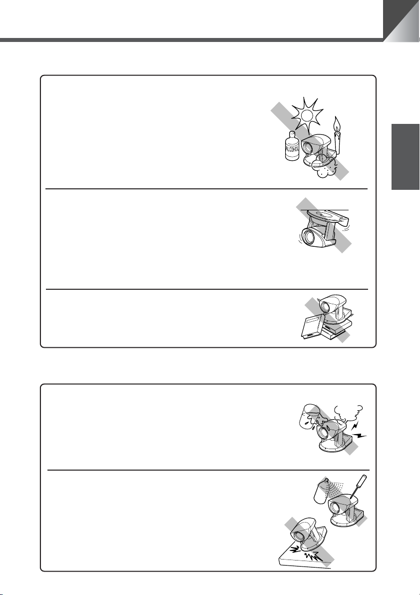
次のような場所には設置しないでください。
火災や感電の原因になります。
● 高温のところ
● 火気の近く
● 湿気やほこりの多いところ
● 直射日光の当たるところ
● 潮風の当たるところ
● 引火性溶剤の近く
設置は確実に行ってください。
天井への設置は、本体と取付け金具を含む重量に充分
耐えられる強度があることをお確かめください。充分
な強度がないと、落下して大けがの原因となります。
また、1 年に 1 度は、必ず取付け部(およびオプショ
ンのワイドコンバータ使用時はワイドコンバータ取付
け部)がゆるんでいないか点検してください。
(ワイドコンバータ WL-37 は VC-C50iR に取付けて
使用することはできません。)
不安定なところや傾斜したところには設置しな
いでください。
落下などによるけがの原因になることがあります。
a 使用上の注意
(アルコールやシンナーなど)
日本語
警告
a
i k
火災注意感電注意
g
プラグをコンセ
ントから抜く
警告
a
i k
火災注意感電注意
b e
禁止 分解禁止
次のような場合はただちに使用を中止し、電源プラグをコンセントから
抜いて、最寄りの販売店にご連絡ください。
そのまま使用すると火災や感電の原因になります。
● 発煙、異音、発熱、異臭などの異常を発見したと
き
● 金属や液体が内部に入ってしまったとき
● 何らかの理由で機器が破損したとき
ご使用の際は次のことをお守りください。
守られない場合、火災や感電の原因になります。
● 機器の近くで可燃性のスプレーを使用しないでく
ださい。
● 分解、改造はしないでください。
● 衝撃を与えないでください。
●
長期間使用しないときは AC アダプタの電
源プラグをコンセントから抜いてください。
5
Page 6
a 安全にお使いいただくために
a 電源に関する注意
警告
a
i k
火災注意感電注意
b
禁止
注意
a
i k
火災注意感電注意
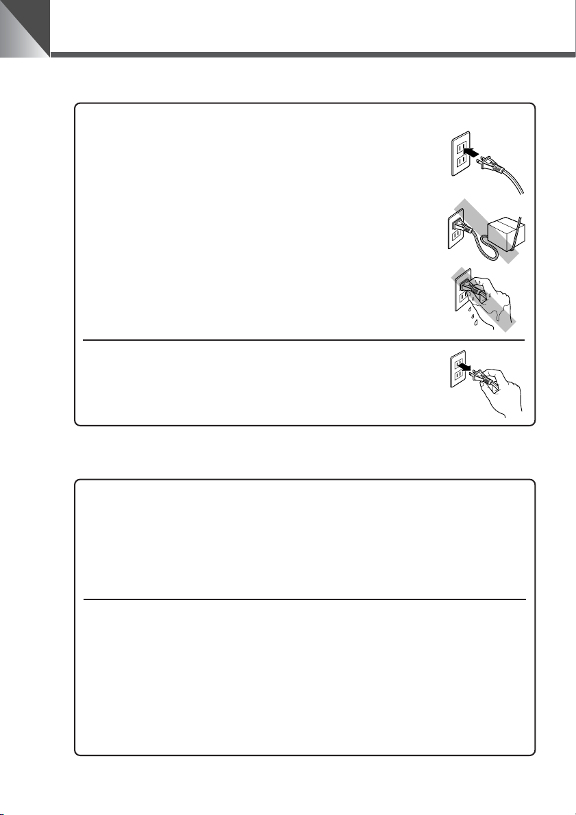
ご使用の際は次のことをお守りください。
守られない場合、火災や感電の原因になります。
● 必ず付属の専用 AC アダプタを使用してください。
また、付属の AC アダプタは、本製品以外には使用
しないでください。
● 電源コードに重いものを載せる、引っ張る、無理に
曲げる、傷つける、加工するなどしないでください。
●ACアダプタを布や布団でおおったり、つつんだり
しないでください。
● 濡れた手で操作しないでください。
● プラグは奥まで確実に差し込んでください。
プラグをコンセントから抜くときは、プラグを持って
抜いてください。
守られない場合、コードが傷つくなどして火災や感電の原因と
なることがあります。
AC100V
a 電池の取扱いに関する注意[リモコン(オプション)使用時]
警告
a
i j
火災注意破裂注意
電池を取扱う際は次のことをお守りください。
守られない場合、破裂、発熱、発火、漏液の原因になります。
● 火の中に入れたり、加熱、ショート、分解したりしないでください。
● 乾電池は充電しないでください。
6
b
禁止
注意
a
i j
火災注意破裂注意
b
禁止
電池を取扱う際は次のことをお守りください。
守られない場合、破裂、発熱、発火、漏液の原因になることがあります。
● 電池を使いきったときや、長時間使用しないときは電池を取りはず
してください。
● 電池を交換するときは 2 本いっしょに交換してください。また、種
類の違う電池をいっしょに使用しないでください。
● +と−の向きを正しく入れてください。
● 万一、液漏れなどで内部の液体が体についたときは、水でよく洗い
流してください。
Page 7
a 持ち運ぶときの注意
a 安全にお使いいただくために
注意
a
i k
火災注意感電注意
b
プラグをコンセ
禁止
ントから抜く
持ち運ぶときは、次の点に注意してください。
● 電源プラグをコンセントから抜いてください。
● 接続コードやケーブルなどを外してください。
コードやケーブルが傷つき、火災や感電の原因にな
ることがあります。
● カメラヘッド部を持たないでください。
g
カメラヘッド部をパン方向、チルト方向に手でまわ
すと故障の原因になります。
a お手入れに関する注意
警告
a
i k
火災注意感電注意
b
プラグをコンセ
禁止
ントから抜く
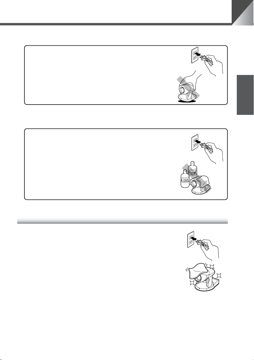
お手入れの際は次のことをお守りください。
守られない場合、火災や感電の原因になります。
● 電源プラグをコンセントから抜いてください。
● アルコールやシンナー、ベンジンなどの引火性溶剤
は使用しないでください。
g
日常のお手入れ
日本語
外装のお手入れ
1. 電源プラグをコンセントから抜く
2. 柔らかい布を水またはうすい中性洗剤で湿らせ、軽く汚れ
を拭き取る
3. 乾いた布で拭く
4. 終了したら電源プラグをコンセントに差し込む
レンズのお手入れ
市販のレンズクリーナーを使用し、レンズ表面の汚れを落とす
■ レンズ表面にほこりや汚れがついていると、オートフォーカスがうまく動作しない
ことがあります。
■ レンズ表面に傷を付けると、画像不良の原因となります。
7
Page 8
ご使用の前に
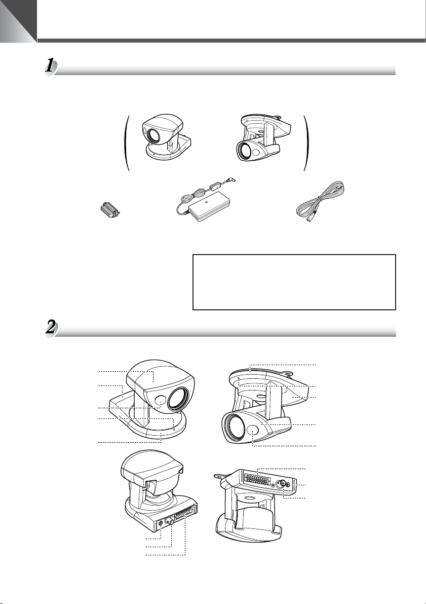
本機および付属品を確認してください
本機を設置する前に、パッケージに以下に示すものがすべて揃っているかどうかをお確かめく
ださい。万が一不足しているものがある場合は、お買い上げの販売店までご連絡ください。
または
VC-C50i 本体 VC-C50iR 本体
マルチコネクタ用
プラグ
● 使用説明書
● 保証書
各部の名称
カメラヘッド
(→ P.17)
雲台(→ P.9)
赤外光照明窓
(→ P.29)
LED
(→ P.14)
リモコン受光部
(→ P.16)
AC アダプタ PA-V16
(ケーブル長:1.5m)
AC ケーブル
(ケーブル長:1m)
■ オプション商品
● リモコンWL-V5(→ P.15)
● ワイドコンバータWL-37(→ P.10)
VC-C50iR では使用できません。
VC-C50i VC-C50iR
(正面)
(背面)
リモコン受光部
(→ P.16)
LED(→ P.14)
雲台(→ P.9)
カメラヘッド
(→ P.17)
赤外光照明窓
(→ P.29)
マルチコネクタ(→ P.10)
DCIN13V 端子
(→ P.10)
ビデオ出力端子
(→ P.10)
8
DCIN13V 端子(→ P.10)
ビデオ出力端子(→ P.10)
マルチコネクタ(→ P.10)
※三脚取付け用のネジ穴は本機底面の中央にあります。
Page 9
設置する
ご使用の前に
a
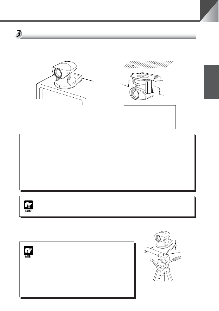
VC-C50i の設置
平らで安定したところに置いて
ご使用ください。
警告
設置は確実に行ってください
● 天井に設置する場合は、お買い上げの販売店にご相談ください。
● 天井への設置は、本体と取付け金具を含む重量に充分耐えられる強度
があることをお確かめください。充分な強度がないと、落下して大け
がの原因となります。
●1年に 1 度は、必ず取付け部(およびオプションのワイドコンバータ
使用時はワイドコンバータ取付け部)がゆるんでいないか点検してく
ださい。
VC-C50iR の設置
ネジ 2ヶ(付属されていません)で
しっかり固定してください。
取付け板
ネジ
(取付け寸法)
•ネジ穴間 :114mm
•ネジ穴径 :直径 6mm
•取付け板厚 :1mm
VC-C50iR
日本語
ネジ
本体の設置角度は水平に対して± 20°(オプションのワイドコンバータ使用時
は± 15°)です。
三脚を使う
三脚取付け用のネジ穴は、本機底面の中央にあります。
● 取付けネジを強く締め付けないでください。
ネジを強く締め付けすぎると、カメラヘッド
が動かなくなるなどの故障の原因になります。
● 三脚は、必ず取付けネジの長さが 6.0mm 未
満のものを使用してください。6.0mm 以上
のものを使用すると、本体が破損することが
あります。また、三脚の台座は直径 30mm
以上のものを使用してください。
30mm
以上
6.0mm
未満
取付け
ネジ
9
Page 10
ご使用の前に
ワイドコンバータを使う
オプションのワイドコンバータ WL-37 を使用すると、広角撮影(焦点距離約 0.74 倍)がで
きます。
ワイドコンバータは水平に、正しく装着し、しっかり締めてください。正しく装着すると、ワ
イドコンバータは約 3 回転して止まります。
ワイドコンバータ
警告
a
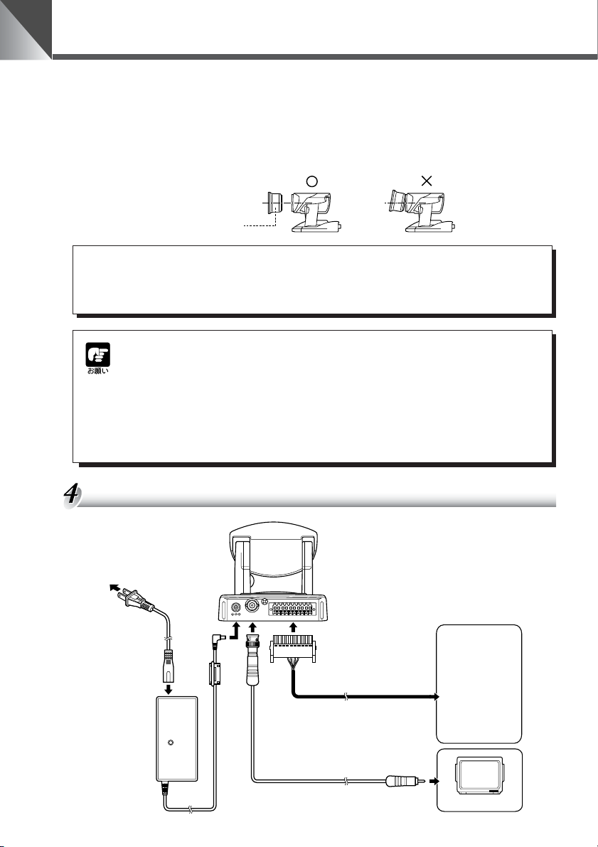
接続する
AC ケーブル
ワイドコンバータ WL-37 は VC-C50iR に取付けて使用するこ
とはできません。使用すると、次第に取付け部がゆるみ、落下し
てけがの原因になります。
● ワイドコンバータ WL-37 以外のものを使用すると、正しく動作しない場合
があります。
● ワイドコンバータ WL-37 をご使用の際は、ズームのワイド側でご使用くだ
さい。ズームのテレ側では、解像感が落ちたりオートフォーカスが合わない
ことがあります。
● ワイドコンバータ取付け時の本体の設置角度は、水平に対して± 15°です。
● ナイトモード時はワイドコンバータの使用はできません。(→ P.29)
(本体背面)
B1
B10
DC IN 13V
VIDEO OUT A1
A10
マルチコネクタ用プラグ
・ パソコン
・他のVC-C50i/
VC-C50iR
・ ネットワーク
カメラサーバー
・ センサー
・ アラーム
・ モニタ
10
AC アダプタ
BNC コネクタ
VIDEO 入力端子へ
モニタ
Page 11
マルチコネクタで接続する
A
10
B
1
B
10
A
10
B
1
B
10
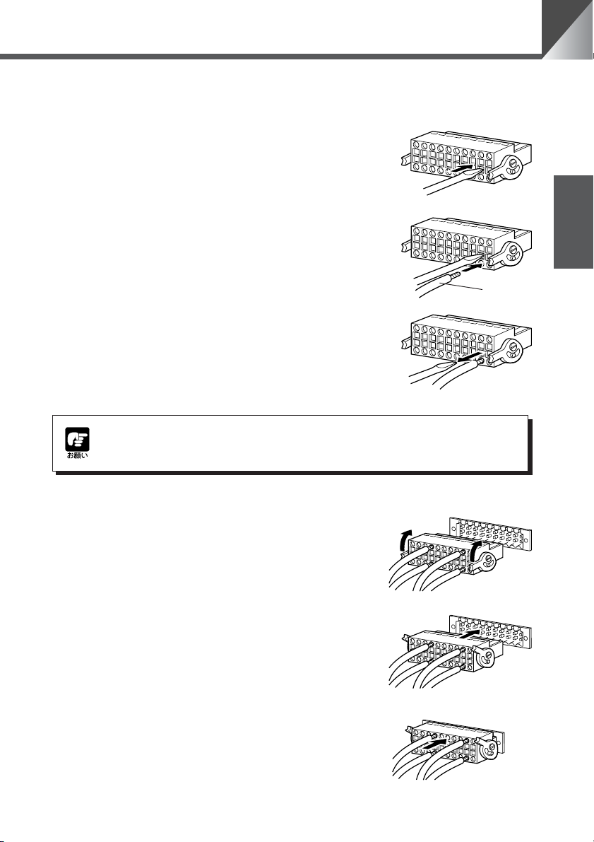
マルチコネクタ用プラグにリード線(AWGNo.28 〜 18)を取り付ける
1. リード線取り付け穴に隣接しているスロットへ、マ
イナスドライバーを奥まで差し込む
■ リード線取り付け穴の内部が開きます。
ご使用の前に
2. マイナスドライバーを差し込んだまま、リード線取
り付け穴にリード線を差し込む
3. リード線が穴から抜けないように押さえながら、マ
イナスドライバーを引き抜く
■ リード線が取り付け穴に固定されます。
同様の手順で、必要なリード線をすべて接続します。
マルチコネクタで接続する場合は、お買い上げの販売店にご相談ください。
マルチコネクタを本機に取りつける
1. マルチコネクタ用プラグのレバーを上げる
2. マルチコネクタ用プラグをマルチコネクタに差し込
む
日本語
リード線
3. マルチコネクタ用プラグを押し込む
■ マルチコネクタ用プラグが、本体背面のポートに固
定されます。
取り外すときは、両側のレバーを同時に押し下げます。
B1
B10
A10
11
Page 12
ご使用の前に
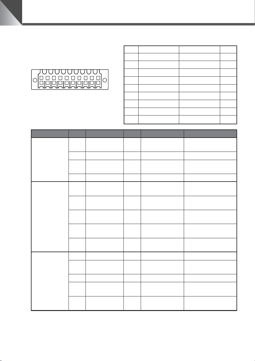
マルチコネクタのピン配列
B1
A1
B10
A10
A1 YGND YOUT B1
A2 CGND COUT B2
A3 RTSOUT CTSOUT B3
A4 TXOUT RXOUT B4
A5 GND GND B5
A6 RTSIN CTSIN B6
A7 TXIN RXIN B7
A8 LightON/OFF- LightON/OFF+ B8
A9 Alarm- Alarm+ B9
A10 Sensor- Sensor+ B10
項目
S 映像出力
RS-232C
(カスケード接
続の次のカメラ
側に接続)
RS-232C
(カスケード接
続の PC 側に接
続)
ピン NO
A1 YGND 出力 ⇒ MONITOR
B1 YOUT 出力 ⇒MONITOR S ビデオの輝度出力
A2 CGND 出力 ⇒ MONITOR
B2 COUT 出力 ⇒MONITOR S ビデオのクロマ出力
A3 RTS 出力 ⇒ NEXTCAMERA
B3 CTS 入力 NEXTCAMERA ⇒
A4 TXD 出力 ⇒ NEXTCAMERA
B4 RXD 入力 NEXTCAMERA ⇒
A5 GND − −
B5 GND − − RS-232C 入力の GND
A6 RTS 出力 ⇒ PC
B6 CTS 入力 PC ⇒ RS-232C 入力の送信可
A7 TXD 出力 ⇒ PC
B7 RXD 入力 PC ⇒
ピン名称
入出力
信号方向 備考
S ビデオの輝度出力
GND
S ビデオのクロマ出力
GND
RS-232C カスケード出
力の送信要求
RS-232C カスケード出
力の送信可
RS-232C カスケード出
力の送信データ
RS-232C カスケード出
力の受信データ
RS-232C カスケード出
力の GND
RS-232C 入力の送信要
求
RS-232C 入力の送信
データ
RS-232C 入力の受信
データ
12
Page 13
ご使用の前に
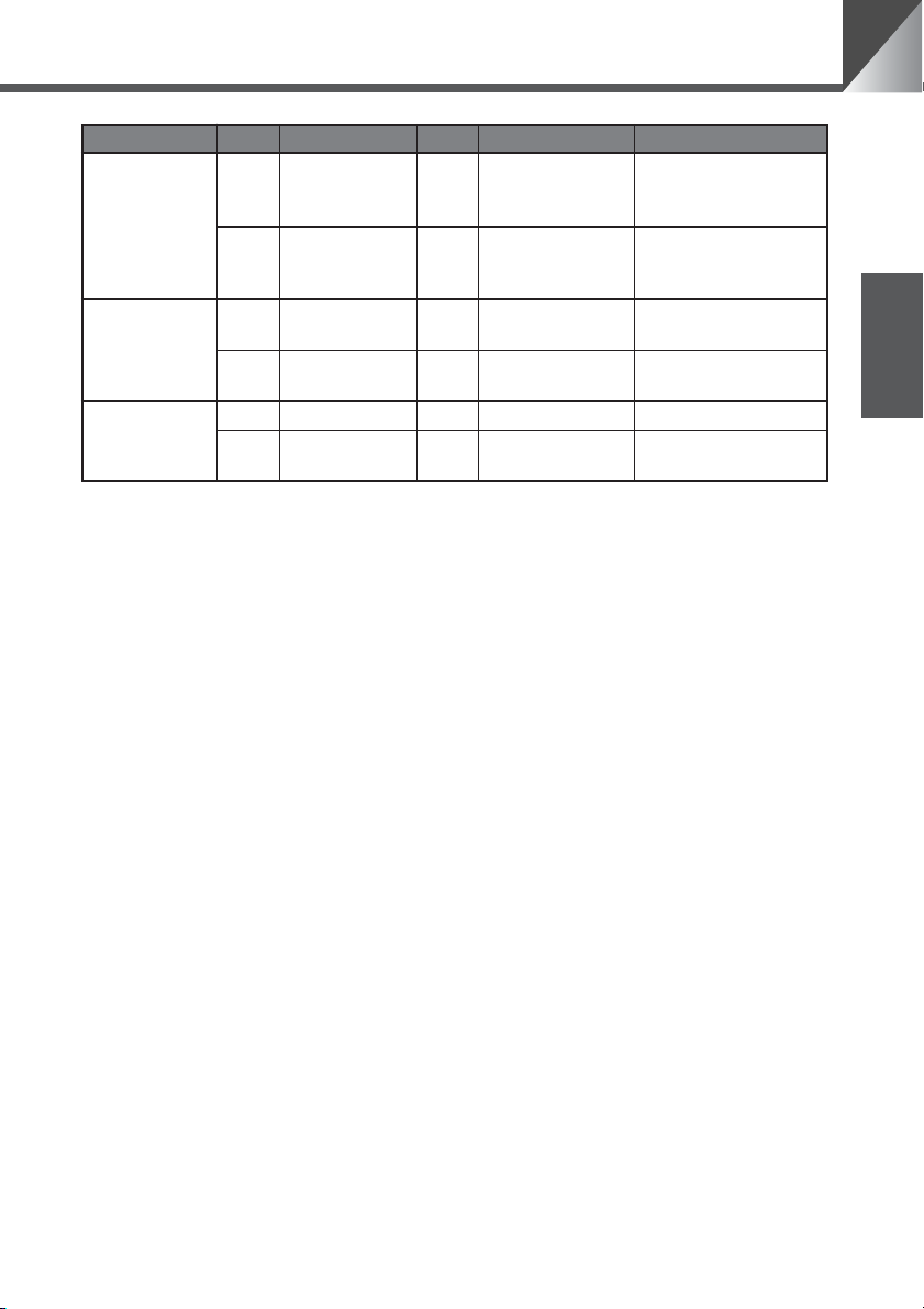
項目
外部照明の制御
信号
アラーム制御信
号
外部センサー入
力
ピン NO
A8 LightON/OFF- 出力 電流吸い込み
B8 LightON/OFF+ 出力 電流はきだし
A9 Alarm- 出力 電流吸い込み
B9 Alarm+ 出力 電流はきだし
A10 Sensor- 入力 電流吸い込み GND
B10 Sensor+ 入力 電流はきだし
ピン名称
入出力
信号方向 備考
外部照明スイッチ FET
SW50V/200mA
(MAX)
外部照明スイッチFET
SW50V/200mA
(MAX)
アラーム制御 FETSW
50V/200mA(MAX)
アラーム制御 FETSW
50V/200mA(MAX)
5V にプルアップダイ
オード保護
外部デバイス入出力端子
外部デバイス入力端子
SENSOR 端子は 2 個の端子(+端子、−端子)で構成されています。−端子は本機内部の
GND に接続されており、+端子は保護ダイオードを介して 10K Ωで +5V にプルアップされ
ています。+端子と−端子にそれぞれリード線を取り付けて両端子間を電気的に短絡(ON)
または開放(OFF)することにより、内部コントローラに対して割り込みを発生させます。
なお接続するセンサーやスイッチは、それぞれの電源や GND と電気的に分離された端子を接
続してください。ON を検知するとホスト PC に対してイベント発行を通知します。
日本語
外部デバイス出力端子
ALARM 端子及び LIGHTON/OFF 端子は各々 2 個の端子で構成されており、それぞれの組
において双方の端子は対等です。内部コントローラの制御により、2 個の端子間を導通状態と
絶縁状態に切り替えることができます。また出力端子には光結合素子が使用されており、本体
の内部回路とは分離されています。
なお出力端子に接続する負荷は次の定格の範囲内で使用してください。
出力端子間の定格
DC 最大電圧:50V
連続負荷電流:120mA
13
Page 14
ご使用の前に
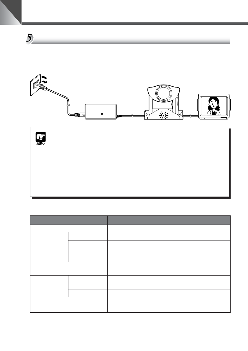
電源の ON/OFF
本機には電源スイッチがありません。AC アダプタの電源プラグを差し込むことで電源 ON と
なります。電源を ON にすると、本機の LED が緑色に点灯します。また、モニタの電源が
ON になっていれば映像が映ります。
AC100V
50/60Hz
AC ケーブル
AC アダプタ
本機
● 電源を OFF から ON にした後で、最初にパソコンまたはリモコンを操作する
と、カメラヘッド位置の初期化が行われます(数秒で終わります)。なお初期
化中は、本機の LED が緑色で点滅(1 秒間隔)します。
● 初期化動作中は絶対にカメラヘッドに触らないでください。正しく初期化さ
れなかったり、故障の原因になります。
● 電源を OFF にした後、再度 ON にする場合は、5 秒以上の間隔をあけてくだ
さい。間隔が短いと動作不良の原因となります。また、電源プラグを抜き差
しする場合は、「a 安全にお使いいただくために・電源に関する注意」
(→ P.6)を必ずお守りください。
LED の表示と本機の状態について
LED の状態 本機の状態
緑色で点灯 カメラ ON の状態(→ P.22)
0.1 秒間隔の点滅 リモコンのボタン操作中
緑色で点滅 0.5 秒間隔の点滅
1 秒間隔の点滅 カメラヘッド位置を初期化中
オレンジ色で点灯
オレンジ色で点滅
赤色で点灯 カメラ OFF の状態(→ P.22)
消灯 電源 OFF(本機に電源が接続されていない状態)
0.1 秒間隔の点滅
0.5 秒間隔の点滅 個別操作をするカメラを選択中または解除中(→ P.32)
プリセットを登録中または実行中(→ P.21)、または設定画
面を表示中(→ P.23)
個別操作を実行中で、個別操作に選択されていないカメラ
(→ P.32)
リモコンのボタン操作中で、個別操作に選択されていないカメ
ラ(→ P.32)
モニタ
14
Page 15
リモコンで操作する
リモコンWL-V5 はオプションです。
リモコンのボタン操作中は、本機の LED は緑色で点滅(0.1 秒間隔)します。
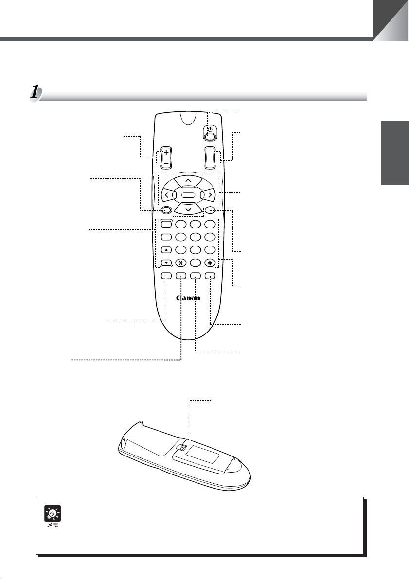
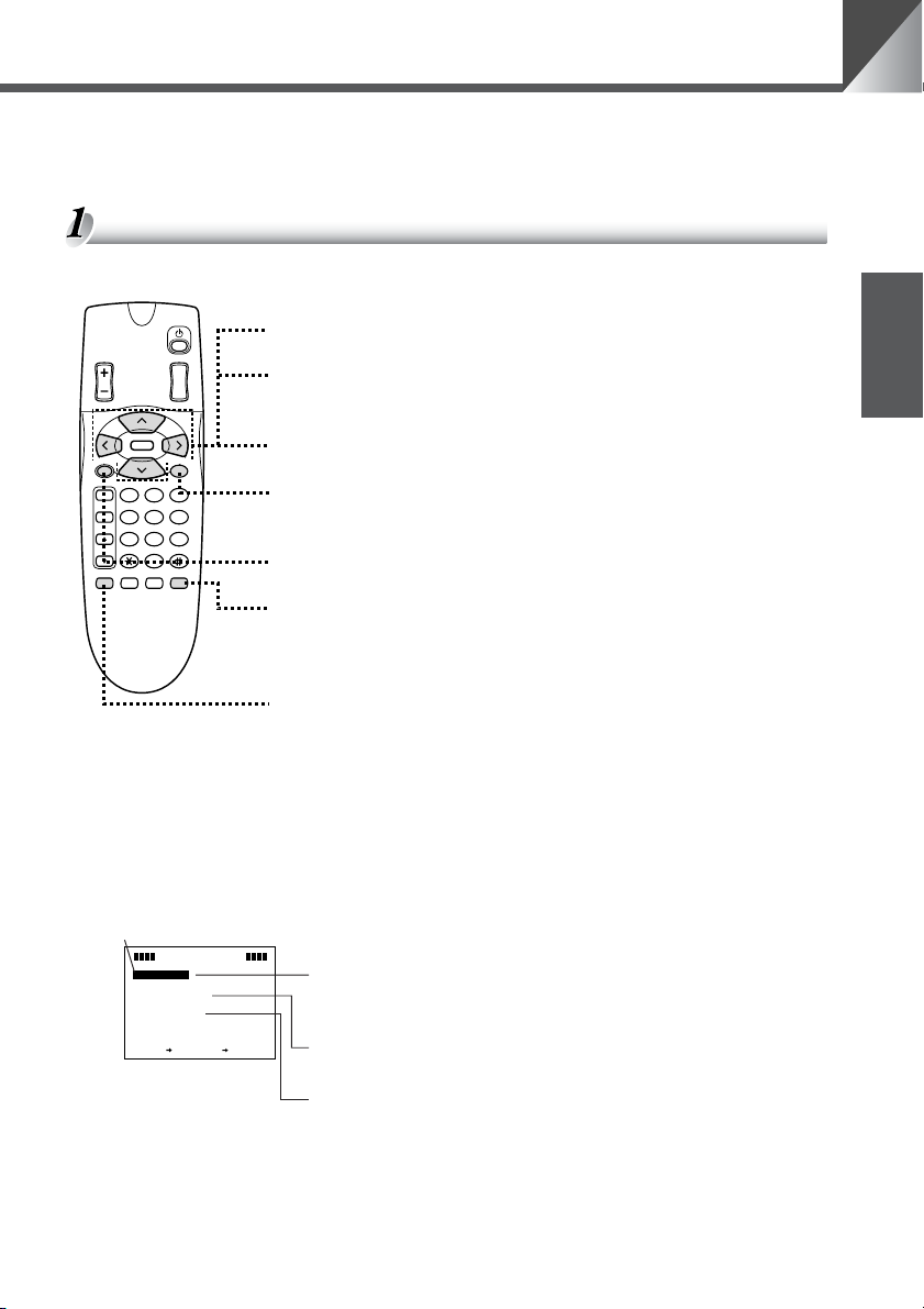
各部の名称
カメラ ON/OFF ボタン(→ P.22)
カメラを ON/OFF します。
BRIGHT ボタン(→ P.20)
モニタの映像の明るさを調節
します。
•+:明るくします。
•−:暗くします。
SET/OK ボタン
(→ P.21、23、31)
プリセットの登録操作で使用
します。また、設定画面では
項目を設定して次の階層に進
めます。
FOCUS ボタン
(→ P.19、20)
ピントを調節します。
•AF :ピント合わせを自動に
します。
•MF:ピントを固定します。
•▲ :ピントを遠くに合わせ
ます。
•▼ :ピントを近くに合わせ
ます。
ONSCREEN ボタン
(→ P.23、25)
日付、時刻、文字を表示した
り、消したりします。
Fn ボタン
使用しません。
BRIGHT
SET/OK CANCEL
AF
MF
∞
ON SCREEN
WIRELESS CONTROLLER
HOME
Fn
WL-V5
ZOOM
0
MENUID
T
W
321
654
987
電池カバー
ZOOM ボタン(→ P.18)
モニタ画面上の被写体を大きくしたり、
小さくしたりします。
• T:被写体を大きくします(ズーム
イン)。
• W:被写体を小さくします(ズーム
アウト)。
カメラコントロールボタン
(→ P.17、23、31)
カメラヘッドの向きを変えたり、カー
ソルを移動させたりします。
V
< >
:上下左右に動かします。
•
^
•HOME :カメラヘッドの向きを正
CANCEL ボタン(→ P.21、23、31)
プリセットの登録操作を中止します。ま
た、設定画面では項目を設定しないでひ
とつ前の階層に戻します。
番号ボタン(→ P.21、32、33)
プリセットの登録 / 実行、および複数の
カメラを個別に選択するときに使用しま
す。* 、 # ボタンは使用しません。
MENU ボタン(→ P.23、31)
MAINMENU 画面を表示したり、消し
たりします。
ID ボタン(→ P.32、33)
複数のカメラを個別に操作するときに
使用します。また、カメラが OFF のと
きでも、このボタンを押すと個別操作
が開始できます。
電池の入れ方は P.16 を参照してください。
面にします。
日本語
本機を使用しないときは、できるだけカメラを OFF(→ P.22)にしてください。節電にな
ります。また、長期間使用しないときは、AC アダプタの電源プラグを抜いて電源 OFF
(→ P.14)の状態にしておくことをお勧めします。ただし、電源を OFF にすると日付、時
刻はクリアされます。
15
Page 16
リモコンで操作する
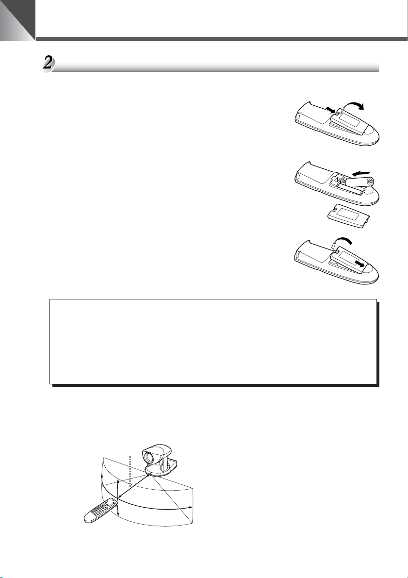
リモコンに電池を入れる
単3乾電池 2 本が必要です。
1. 電池カバーを取りはずす
2. 電池を入れる
■+と−の向きに注意して入れてください。
3. 電池カバーを取付ける
16
警告
a
i k
火災注意感電注意
j b
破裂注意 禁止
電池を取扱う際は次のことをお守りください。
守られない場合、破裂、発熱、発火、漏液の原因になります。
● 火の中に入れたり、加熱、ショート、分解したりしないでください。
● 乾電池は充電しないでください。
リモコンの届く範囲
図に示す範囲内で、リモコンをカメラのリモコン受光部に向けて操作してください。ただし、
電池の残量や障害物などによって、リモコンの届く範囲は変わります。(VC-C50iR も同様で
す。)
90°
5m
30°
90°
30°
Page 17
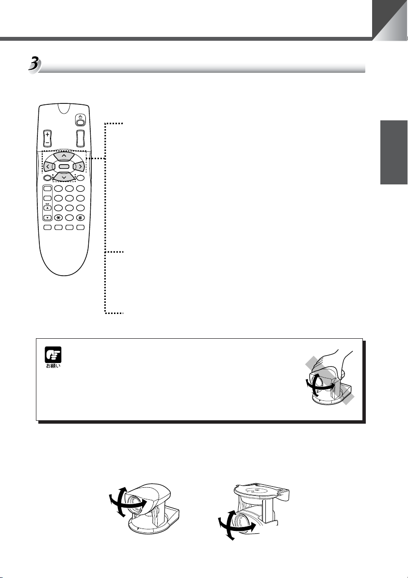
カメラヘッドの向きを変える(パン / チルト / ホーム)
カメラヘッドの向きを変えます。
左右に動かすとき(パン)
BRIGHT
HOME
SET/OK CANCEL
AF
MF
0
Fn
ON SCREEN
ZOOM
MENUID
T
W
321
654
987
4 、 6 ボタンを押す
■ カメラに向かってリモコンを操作しているとき、モニタの映
像は押されたボタンの矢印と同じ方向に動き、カメラヘッド
は矢印と逆の方向に動きます。
DIRECTIONMIRROR(→ P.26)を[ON]に設定すると、
カメラヘッドは押されたボタンの矢印と同じ方向に動きま
す。
■ ボタンを押し続けると速度が次のように変化します。
低速→中速→高速
上下に動かすとき(チルト)
8 、 5 ボタンを押す
■ ボタンを押し続けると速度が次のように変化します。
低速→中速→高速
正面に戻すとき(ホーム)
h ボタンを押す
■ 高速でカメラヘッドを正面に戻します。
リモコンで操作する
日本語
カメラヘッドの向きを手で変えないでください。
カメラヘッドの向きを誤って手で変えたり、ものなどが当たっ
たりしてカメラヘッドが直接動いてしまった場合は、必ず h
ボタンを押してください。カメラが記憶しているパン / チルト
位置と、実際のパン / チルト位置のずれがなくなり、正常に動
作するようになります。
カメラヘッドの動作範囲
カメラヘッドの水平位置からの動作範囲を示します。VC-C50i の上方向の初期設定は
30°ですが、90°まで設定することができます(→ P.27)。
30°
100°
30°
100°
10°
170°
170°
VC-C50i VC-C50iR
90°
17
Page 18
リモコンで操作する
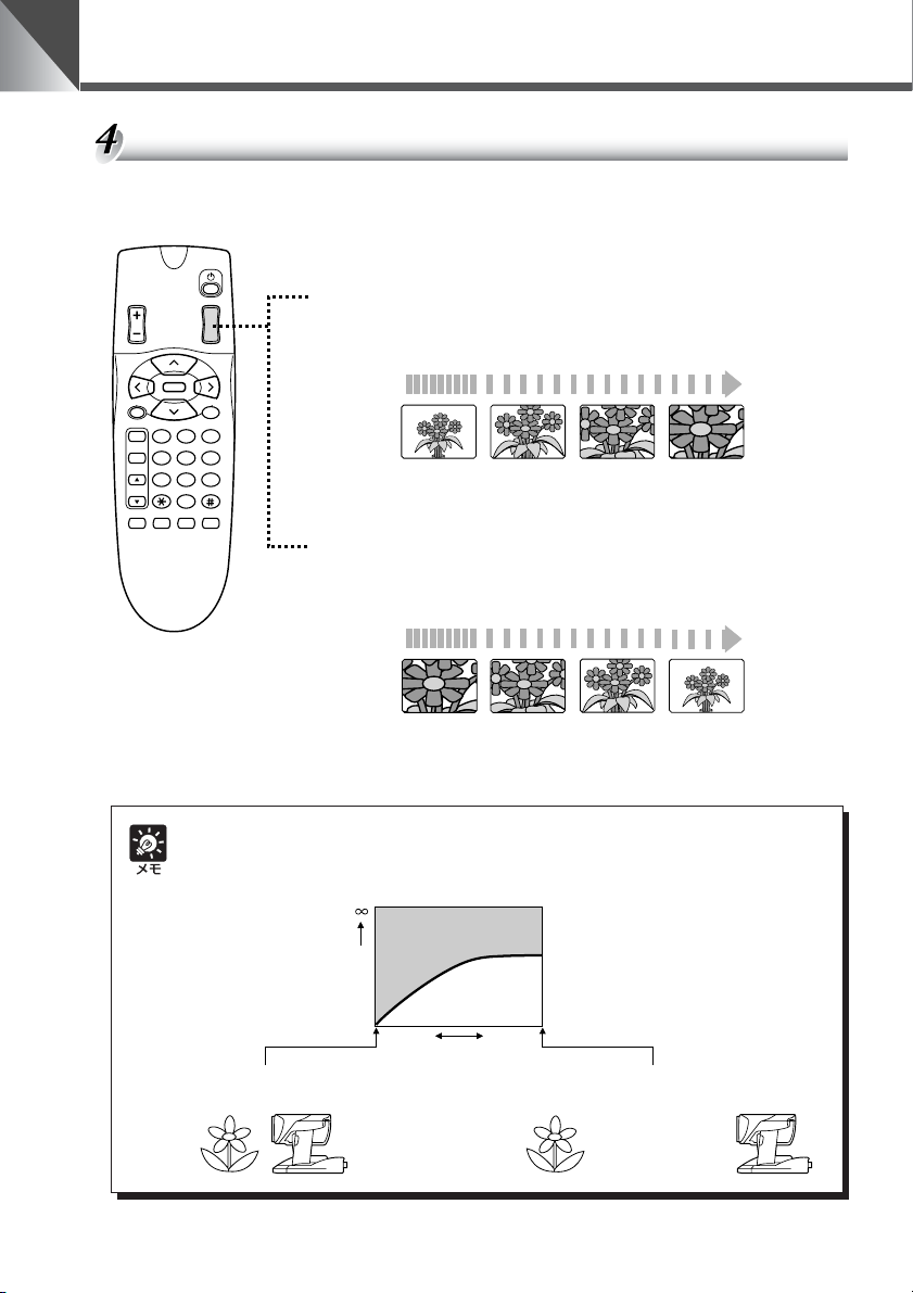
ズームイン / ズームアウト(テレ / ワイド)
モニタの画面上の被写体を大きく(ズームイン)したり、小さく(ズームアウト)したりしま
す。
ズームインするとき(テレ)
BRIGHT
SET/OK CANCEL
AF
MF
∞
ON SCREEN
ZOOM
HOME
0
Fn
T
W
321
654
987
MENUID
t 側を押す
■ ボタンを押し続けるとズーム速度が次のように変化します。
低速 高速
ズームアウトするとき(ワイド)
w 側を押す
■ ボタンを押し続けるとズーム速度が次のように変化します。
低速 高速
18
ピントの合う範囲
ズームの位置によっては、ピントが合わない場合があります。
カメラが近づける距離の変化
距離
1cm
約 1cm まで(ナイトモード時は約 2cm まで)
ズームのワイド端
ピントの合う範囲
ズームの位置
1.6m
約 1.6m まで(ナイトモード時は約 2.3m まで)
ズームのテレ端
Page 19
リモコンで操作する
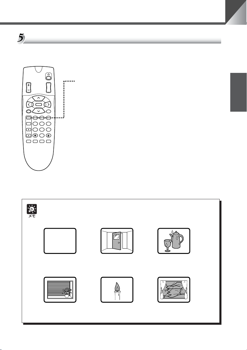
ピントを調節する(フォーカス)
被写体にピントを合わせます。ピントを自動で合わせるオートフォーカスと、手動で合わせる
マニュアルフォーカスがあります。(初期設定はオートフォーカスです。)
オートフォーカスにするとき
BRIGHT
SET/OK CANCEL
AF
MF
∞
ON SCREEN
ZOOM
T
W
HOME
321
654
987
0
MENUID
Fn
a ボタンを押す
■ ピントは自動的に合います。
日本語
オートフォーカスではピントの合いにくい被写体
次のような被写体は、オートフォーカスではピントが合いにくいことがあります。そのよう
なときは、マニュアルフォーカス(→ P.20)でピントを合わせてください。
斜めになっているもの白い壁など明暗の差が
ないもの
横じまのあるもの
いもの
強い光が反射している
もの
ガラス越しのもの炎や煙などの実体のな
19
Page 20
リモコンで操作する
BRIGHT
ZOOM
T
W
ピントを固定にするとき
n ボタンを押す
■ オートフォーカスを解除し、ピントが固定になります。
HOME
SET/OK CANCEL
AF
MF
∞
0
Fn
ON SCREEN
321
654
987
MENUID
近くにピントを合わせるとき
r ボタンを押す
■ マニュアルフォーカスになり、近くにピントを合わせること
ができます。
■ ボタンを押し続けると、ピントの合う位置が近くに移動し続
けます。
遠くにピントを合わせるとき
e ボタンを押す
■ マニュアルフォーカスになり、遠くにピントを合わせること
ができます。
■ ボタンを押し続けると、ピントの合う位置が遠くに移動し続
けます。
■ ズームの位置によってはピントが合わない場合があります
(→ P.18)。
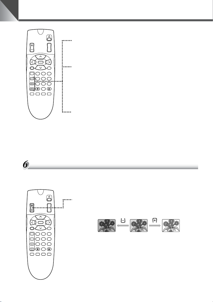
明るさを調節する(ブライト)
映像を明るくしたり、暗くしたりします。電源を ON にしたときは標準の明るさになります。
明るくする、暗くする
BRIGHT
SET/OK CANCEL
AF
MF
∞
ON SCREEN
ZOOM
HOME
0
Fn
T
W
321
654
987
MENUID
明るくするときは z 側を、暗くするときは x 側を押す
■ ボタンを押している間、だんだん明るく(暗く)なります。
明るく標準の明るさ暗く
■ 標準の明るさが AEREFERENCE の[5]に相当します
(→ P.28)。また、最大の明るさが[10]に、最大の暗さが
[1]に相当します。
■ いちじるしく暗い場所では、明るさを調節することができな
い場合があります。
20
Page 21
リモコンで操作する
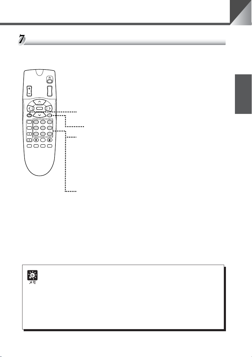
カメラの状態を記憶させる(プリセット)
カメラヘッドの向き、ズームの位置および明るさの状態を登録します。最大 9 件(1 〜 9)ま
で登録でき、電源を OFF またはカメラを OFF にしても登録内容は消えません。
状態を登録するとき
BRIGHT
SET/OK CANCEL
AF
MF
∞
ON SCREEN
ZOOM
T
W
1. カメラヘッドの向き、ズームの位置および明るさを決め
る
■ フォーカスの情報は登録されません。
HOME
321
654
987
0
MENUID
Fn
2. s ボタンを押す
■ 本機の LED が緑色で点滅(0.5 秒間隔)します。
■ 操作を中止するときは c ボタンを押してください。
3. 1 〜 9 ボタンを押す
■ 登録が終了し、本機の LED が緑色で点灯します。
■ すでにプリセットが登録されている場合は上書きされます。
登録内容を実行するとき
1 〜 9 ボタンを押す
■ 登録されているカメラヘッドの向き、ズームの位置および明
るさになります。
日本語
● プリセット動作時のパン / チルトの動作速度は、設定画面で設定したパン / チルトの動
作速度になります。また、[AUTO]の場合は最高速になります(→ P.26)。
● プリセットの登録内容は常に上書きされます。すでに登録してあるプリセットをクリア
することはできません。ただし、COMMAND のモードを変更した場合はクリアされま
す(→ P.29)。
● マニュアルフォーカスになっている場合、プリセットの実行をするとピントが合わない
場合があります。このようなときはオートフォーカスにするか、マニュアルでピントを
合わせてください。
21
Page 22
リモコンで操作する
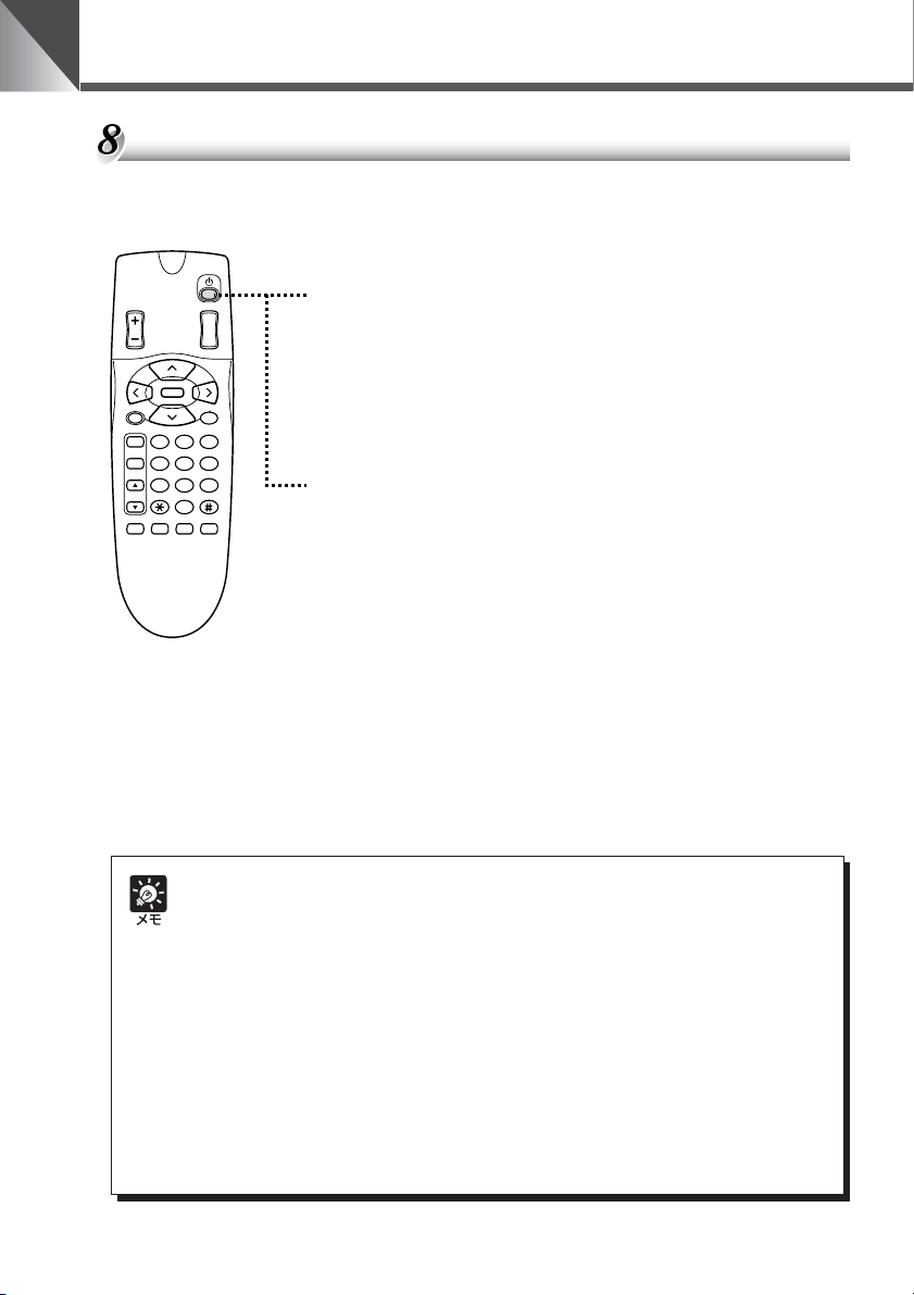
カメラを ON/OFF する
カメラの ON/OFF は p(カメラ ON/OFF)ボタンで行います。カメラを OFF にしてもプリ
セット、日付、時刻、ID 番号はクリアされません。
カメラを OFF にするとき
BRIGHT
HOME
SET/OK CANCEL
AF
MF
∞
0
Fn
ON SCREEN
ZOOM
MENUID
T
W
321
654
987
カメラ ON の状態で p ボタンを押す
■ 映像が消え、本機の LED が赤色で点灯します(カメラ
OFF)。p ボタンおよび i ボタン以外のリモコン操作は受
付けません。
カメラを ON にするとき
カメラ OFF の状態で p ボタンを押す
■ 映像が映り、本機の LED が緑色で点灯します(カメラ ON)。
これ以降、すべてのリモコン操作を受付けます。
■ カメラが O FF のときでも、i ボタンを押すと、本機の LED
はオレンジ色に点滅して個別操作が開始できます
(→ P.32)。
22
● カメラを OFF にしてもカメラへの通電はされており、本機の電源は OFF(→ P.14)さ
れません。従って、カメラを OFF にしてもプリセット、日付、時刻、ID 番号はクリア
されません。
● ナイトモード状態において、リモコンでカメラを OFF にすると、内蔵赤外照明は消灯し
ますが、ナイトモードは保持されます。
この状態でリモコンにより再度カメラを ON にしても、内蔵赤外照明は点灯しません。
設定画面よりナイトモードを一旦 OFF にして、再度 ON すると、内蔵赤外照明が点灯
します。
● 本機を使用しないときは、できるだけカメラを OFF にしてください。節電になります。
また、長期間使用しないときは、AC アダプタの電源プラグを抜いて電源 OFF の状態に
しておくことをお勧めします。ただし、電源を OFF にすると日付、時刻はクリアされま
す。
Page 23
いろいろな設定
設定画面を表示して、時計や文字の設定および表示、カメラの動作などを設定することができ
ます。
設定操作に使用するボタン
設定は、以下に示すリモコンのボタンを使って行います。
58 ボタン:カーソルを上下に移動します。
BRIGHT
SET/OK CANCEL
AF
MF
∞
ON SCREEN
ZOOM
T
W
HOME
321
654
987
0
MENUID
Fn
6 ボタン :カーソルを右に移動します。または画面を次の
階層に進めます。
4 ボタン :カーソルを左に移動します。
c ボタン :項目を設定しないでひとつ前の階層に戻しま
す。
s ボタン :項目を設定して次の階層に進めます。
m ボタン :設定画面を表示したり、消したりします。設定
画面を表示中、本機の LED は緑色で点滅(0.5
秒間隔)します。
日本語
o ボタン :時計や文字などを表示したり、消したりします
設定画面の説明
m ボタンを押すと設定画面が表示できます。
カーソル
NME
NU
A
I
M
MENU
E
S
T
P
MENU
LAY
I
S
D
C
M
A
E
MENU
A
R
CEL
A
E
C
B
N
X
TSET
KCA
N
SETMENU :本機をマルチコネクタを介してパソコンやその他
DISPLAYMENU:時計合わせや撮影画面にカメラ番号などの文字が
CAMERAMENU:カメラヘッドのパン / チルトの動作速度、動作範
(→ P.25)。未設定の場合は日付
(01.JAN.’00)と時刻(00.00.00AM)が点
滅します。また、設定画面を表示中、このボタ
ンは無効です。
の装置で制御するための設定ができます
(→ P.30、31)。
入力できます(→ P.24、25)。
囲、カメラの明るさやナイトモードの設定変更が
できます(→ P.26 〜 29)。
23
Page 24
いろいろな設定
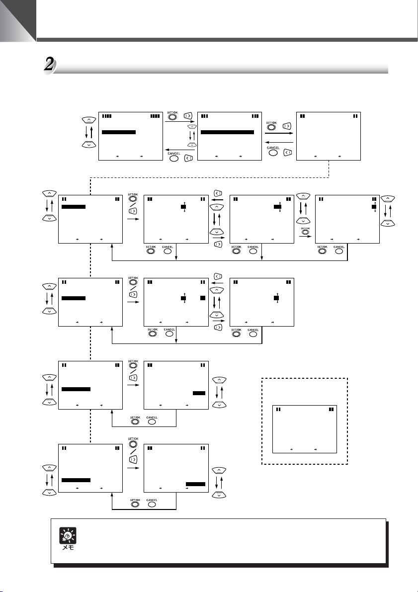
時計を合わせる
日付、時刻を設定します。好みに応じて TIMESTYLE および DATESTYLE を決めてくださ
い。
E
S
E
S
TIM
ATE
D
N
E
S
E
S
TIM
ATE
D
N
E
S
E
S
TIM
ATE
D
N
E
S
E
S
TIM
ATE
D
N
DTE&
A
D
ATE
T
T
TIM
ESTYLE
STYLE
E
X
TSET
DTE&
A
D
ATE
T
T
TIM
ESTYLE
STYLE
E
X
TSET
DTE&
A
T
D
ATE
T
TIM
ESTYLE
STYLE
E
X
TSET
DTE&
A
D
ATE
T
T
TIM
ESTYLE
STYLE
E
X
TSET
M
NME
NU
A
I
MENU
E
S
T
P
MENU
LAY
I
S
D
C
M
A
MENU
E
A
R
A
C
E
B
KCA
X
N
TSET
T
IME
SE
TTINGS
JA10
0
.0.
’
N
E
00:00:0
M
A
0
/
A
MMMMP
//
D
Y
D
Y
CEL
A
C
B
KCA
N
N
CEL
S
DTE&
E
T
X
/
D
T
D
TXT
/
T
IME
NG
SSE
TTI
A
D
ATE
TEN
SET
0.
N
.10
’
0
AJ
CEL
N
CA
A
C
B
K
/
T
IME
TTINGS
SE
00
.A.J
N
10
E
’
00:00:
M
A
0
0
/
A
MMMMP
//
DD
YY
CEL
A
C
B
N
KCA
S
N
DTE&
E
T
X
E
T
IME
NG
S
SE
TTI
A
TIM
T
0
E
SET
M
00:00:
A
0
0
A
CEL
C
B
K
CA
N
/
T
IME
TTINGS
SE
00
.AJ.10
’
N
E
M
A
00:00:0
0
/
MMMMP
A
//
Y
DD
Y
A
CEL
C
B
KCA
N
TIM
DTE&
A
ESTYLE
SETSE T
T
IME
TTI
NG
S
SE
24
H
M
P/A
M
CEL
CEL
CA
CA
N
N
/
T
IME
SE
TTINGS
’.AJ.10
00
N
E
M
A
00:00:0
0
/
MMMMP
A
//
DD
YY
CEL
BAC
KCA
N
DTE&
A
ATE STYLE
D
T
IME
TTI
SE
NG
S
MM
DD//YY
//
MM
YY
DD
CEL
CEL
CA
CA
N
N
SETSE T
M
E
NU
SDI
PLAY
D
ISPLAY
A
TE
I
M
E
I
S
D
E
&TIM
A
T
D
ITXT
SPLAY
SETT I
E
X
N
TSET
O
F
F
P
Y
LA
NG
S..
E
SETT I
NG
S..
CEL
A
C
B
N
KCA
DTE&
A
E
S
D
ATE
T
ENX
T
SET
/
F
F
O
O
F
F
/
T
IME
TTI
NG
SSE
0.
N
.21
J
’
0
U
CEL
N
CA
A
C
B
K
/ /
T
IME
TTINGS
SE
DTE&
A
E
S
TIM
E
T
ENX
T
SET
M
A00:03:
10
A
C
CEL
B
K
CA
N
/
24H および YY/MM/DD を
選択したときの表示例
DTE&
A
E
S
D
T
E
S
T
TIM
TIM
ESTYLE
ATE
D
E
X
N
TSET
T
IME
SE
NG
S
TTI
DTE&
E
S
E
S
TIM
ATE
D
N
A
D
ATE
T
T
TIM
ESTYLE
STYLE
E
X
TSET
.
N
0
A
J
.10
DTE&
E
T
’
A
00:00:
0
0
/
A
//
DD
YY
CEL
A
C
B
N
KCA
T
IME
A
D
ATE
CEL
CA
N
SETSE T
E
S
同様にして分、秒を設定
T
IME
TTINGS
SE
21
ATE
E
STYLE
.60.00’
00:03:31
H
2
4
MM
YY//DD
A
CEL
C
B
KCA
N
0
M
MMMMP
TTI
NG
SSE
.21
.
N
0
0
J
’
U
CEL
N
CA
/
24
電源を OFF(→ P.14)にすると、設定した日付や時刻はクリアされ、工場出荷時の初期設
定になります(→ P.36)。ただし、カメラを OFF(→ P.22)にしたときはクリアされま
せん。
Page 25
いろいろな設定
文字の設定
設定できる文字は、英文字(A 〜 Z)、数字(0 〜 9)、および記号(<>-/.:(スペース))
です。文字候補領域以外の場所ならどこにでも設定することができます。設定は w と e を繰
り返して 1 文字ずつ行います。複数行にわたる場合は 1 行ごとに q から t を繰り返します。
文字を削除したいときはカーソルを l(バックスペース)に置き、s ボタンを押して 1 文
字ずつ消します。
M
NME
NU
A
I
MENU
E
S
T
P
MENU
LAY
I
S
D
C
M
A
MENU
E
A
R
A
C
E
X
B
TSET
KCA
N
q
M
E
NU
SDI
PLAY
D
ISPLAY
A
D
TE
I
T
M
E
P
I
S
D
E
&TIM
E
A
T
D
D
ITXT
SPLAY
SETT I
TXT
CEL
N
E
X
N
TSET
LA
NG
Y
SETTI
S..
B
ON
ON
NG
S..
ON
A
C
C
EL
KCA
N
t
24 桁
11 行
文字カーソル
文字候補領域には
設定したい位置
w
で位置を
決定
設定できません
文字候補
e
文字を選んで
KVJUITHSGRFQEPDOCNBMA
XLW
日本語
r 終了したら[OK]まで
98O7654:3.2
10ZY
<
>
-
A1
/
CA
MER
カーソルを移動
CK
KVJUITHSGRFQEPDONBMA
C
W
バックスペース
スペース
時計、文字の表示 / 非表示の設定
日付、時刻、文字などを表示したいときは ON、表示したくないときは OFF に設定します。
ON に設定した場合、o ボタンを押すことで表示したり、消したりできます。
NME
NU
A
I
M
MENU
E
S
T
P
MENU
LAY
I
S
D
C
M
A
E
MENU
A
R
A
CEL
C
E
B
KCA
X
N
TSET
N
時計および文字の表示例
21.60.0
CAMERA1
0’
M
P00:0
:1
3
0
M
E
NU
SDI
/
/
PLAY
D
ISPLAY
A
D
TE
I
T
M
E
I
D
S
E
A
&TIM
T
D
D
ITXT
SPLAY
SETTI
TXT
E
X
N
TSET
O
LA
SETT I
NG
FF
Y
FF
O
NG
S..
OFF
S..
A
CEL
C
B
KCA
N
P
E
A
D
/
/
M
E
NU
SDI
PLAY
D
ISPLAY
A
D
TE
I
T
M
E
P
I
S
D
E
A
&TIM
E
T
D
D
ITXT
SPLAY
SETTI
TXT
E
X
N
TSET
LA
SETT I
NG
FF
O
FF
Y
O
NG
S..
O
FF
S..
CEL
BAC
N
KCA
T
/
/
M
E
NU
SDI
PLAY
D
ISPLAY
A
D
TE
I
T
M
E
P
I
S
D
E
&TIM
E
A
T
D
D
ITXT
SPLAY
SETTI
TXT
E
X
N
TSET
LA
SETT I
NG
FF
O
FF
Y
O
NG
S..
S..
A
C
B
KCA
N
/
O
FF
CEL
/
M
E
NU
SDI
PLAY
D
ISPLAY
TE
SETSET
ON
O
FF
CEL
CEL
CA
N
N
CA
/
M
E
NU
SDI
PLAY
I
M
E
P
I
S
D
SETSET
ON
LAY
FF
O
CEL
CEL
CA
N
N
CA
/
M
E
NU
SDI
PLAY
D
SETSET
ITXT SPLAY
ON
O
F
F
CEL
CEL
CA
N
N
CA
/
L
X
25
Page 26
いろいろな設定
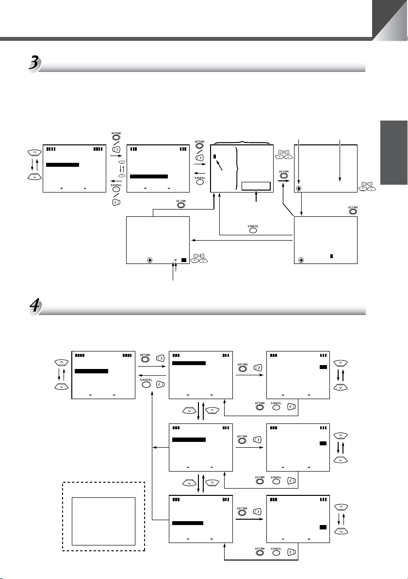
カメラヘッドの動作スピードおよびパン動作の設定
カメラヘッドのパン / チルトの動作スピード、および DIRECTIONMIRROR(カメラヘッド
のパン方向の動作)を設定します。
M
NME
NU
A
I
MENU
E
S
T
P
MENU
I
LAY
S
D
C
M
A
MENU
E
R
A
CEL
A
E
C
B
N
X
TSET
KCA
N
N
PA
SPEE
T
IT
L
SPEE
M
V
LE
ARANGEDEFAULT..
O
B
A
E
SETT I
DIR
ECTI
G
NH
E
X
N
TSET
N
PA
SPEE
T
IT
L
SPEE
M
V
LE
ARANGEDEFAULT..
B
O
E
A
SET I
DIR
ECTI
G
NH
E
X
N
TSET
M
AME
NU
E
R
AC
D
UTO
A
AUT
OD
NNG
S
..
O
MIRROR
O
ETI
AME
R
D
S
MIRROR
ETI
FF
O
CEFFL
A
C
B
N
KCA
NU
A
UTO
AUT
OD
..
FF
O
FF
O
CEL
BAC
N
KCA
M
O
D
M
E
AC
NNG
O
M
O
D
M
AC
PA
N
SPEE
SETSE T
M
AC
PA
N
SPEE
SETSE T
/
M
AC
T
IT
L
SPEE A
SETSE T
M
AC
T
ITL
SPEE
SETSE T
/
AME
NU
E
R
D
A
UUT
O
NAM
AL
CEL
CEL
CA
CA
N
N
AME
NU
E
R
D
A
UUT
O
NAM
AL
CEL
CEL
CA
CA
N
N
M
AME
E
R
AC
PA
N
SPEE
D
-2-3-4-5-6-7-8-9-
1
CA
N
SETSE T
NU
N
AMAL
U
10
CEL
CEL
CA
N
/
AME
NU
E
R
UTOD
MANU
AL
CEL
CEL
CA
N
N
CA
AME
NU
E
R
D
A
UUT
O
L
N
AMA
CEL
CEL
CA
N
N
CA
M
AME
NU
E
R
AC
T
IT
L
SPEE
D
1
-2-3-4-5-6-7-8-9-10
CEL
CA
N
SETSE T
N
AMALU
CEL
N
CA
/
26
M
AME
PA
N
SPEE
T
IT
L
SPEE
V
M
LE
ARANGEDEFAULT..
B
O
A
E
SETT I
DIR
ECTI
G
NH
E
X
N
TSET
NU
E
R
AC
M
A
D
UTO
AUT
OD
NNG
S
..
FF
D
MIRROR
ETI
O
FF
O
CE
L
BAC
KCA
N
O
O
IRECTI
D
AME
NU
E
R
AC
M
O
NMI
SETSE T
OON
RROR
F
F
CEL
CEL
CA
N
N
CA
● DIRECTIONMIRROR を[ON]に設定すると、カメラヘッドはリモコンの
46 ボタンの矢印と同じ方向に動きます(→ P.17)。
●
ここで設定されたパン / チルトの動作速度は、プリセット動作時(→ P.21)の
パン / チルトの動作速度になります。また、[AUTO]のときは最高速になります。
Page 27
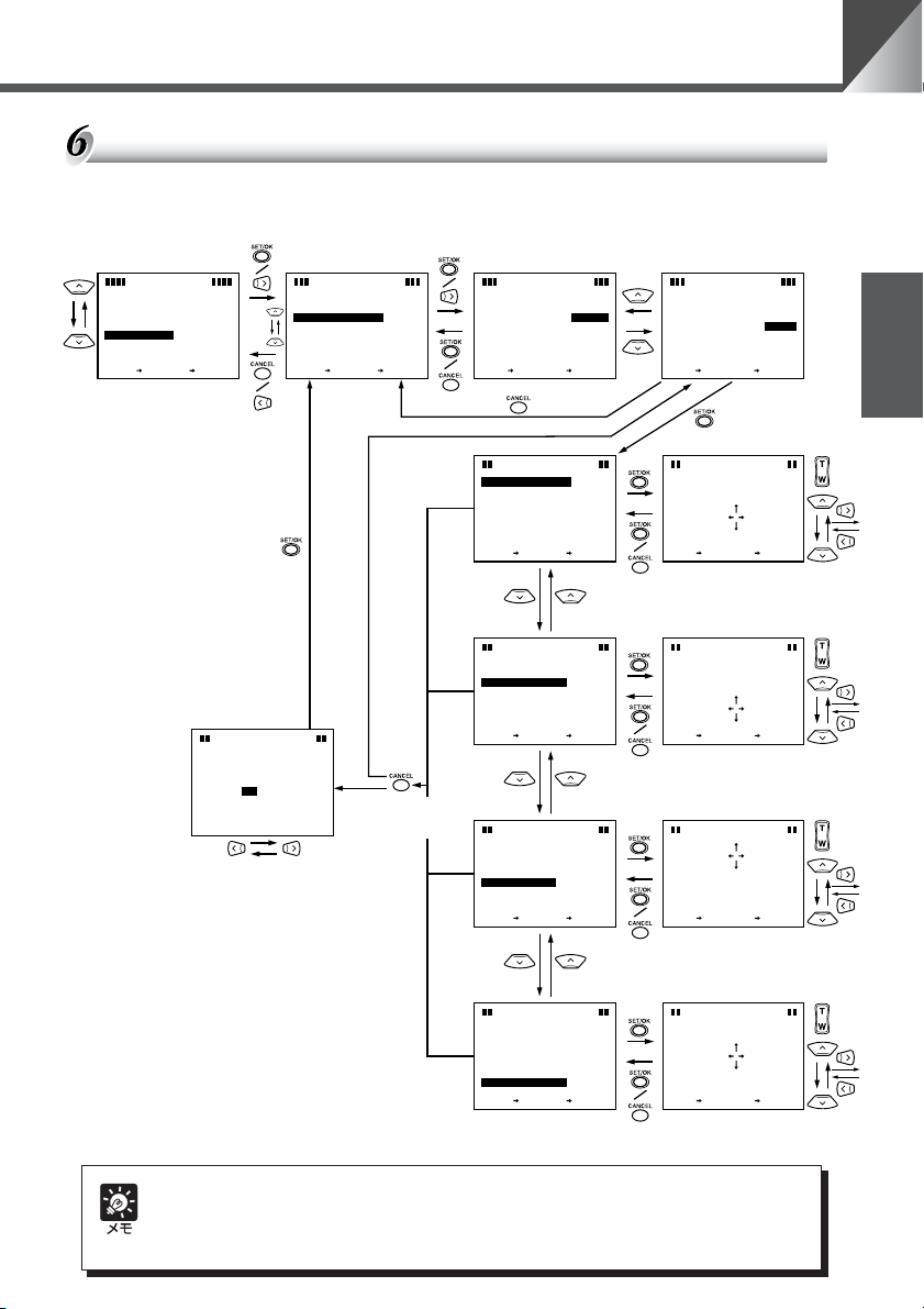
いろいろな設定
カメラヘッドの動作範囲の設定
カメラヘッドのパン / チルトの動作範囲(→ P.17)を制限します。映像を見ながら制限した
い位置までカメラヘッドを移動して設定します。
M
NME
NU
A
I
MENU
E
S
T
P
MENU
LAY
I
S
D
C
M
A
MENU
E
R
A
CEL
A
E
C
B
X
N
TSET
KCA
N
[YES] を選択すると保存して
終了
[NO] を選択すると保存せずに
終了
M
SAVE
AOV
BLE E
SETTINGS?
YES
GNAR
NO
M
AME
E
R
AC
N
PA
SPEE
D
T
IT
L
SPEE
V
M
ARANGEDEFAULT..
LE
B
O
A
E
SETTTI
NNG
S
..
DIR
ECTI
O
MIRROR
M
G
NHEIO
D
A
E
B
X
N
TSET
設定が変更されて
いるとき
C
NU
KCA
設
定
が
変
更
さ
れ
て
い
な
い
と
き
M
AME
NU
E
R
UTO
A
AUT
OD
O
FF
O
CEFFL
N
AC
V
M
ARANGEDE
LE
B
O
SETSE T
M
AOV
BLE E
I
I
R
L
GH
T
M
L
I
L
EFT
M
ITSE
I
L
M
U
P
ITSE
O
I
D
L
W
M
N
E
X
N
TSET
CA
ITSE
ITSE
U
LT..
FA
MANU
AL
CEL
CEL
CA
N
N
GNAR
+
GED
000
T
+
T
GED
000
+
T
GED
000
+
T
GED
000
A
CEL
C
B
KCA
N
M
E
AC
V
M
ARANGEDE
LE
B
O
SETSE T
M
AOV
BLE E
I
I
R
L
GH
T
M
SETSE T
AME
NU
R
FA
MANU
CEL
CA
CA
N
N
GNAR
+
ITSETGED
CEL
CA
CA
N
N
U
LT..
AL
CEL
000
CEL
日本語
映像を見ながら制限した
い位置まで移動する
M
AOV
GNAR
BLE E
+
ITSE
I
I
R
L
GH
T
M
ITSE
L
I
L
EFT
M
ITSE
I
L
M
U
P
ITSE
O
I
D
L
W
M
N
E
X
N
TSET
GED
000
T
+
T
GED
000
+
T
GED
000
+
T
GED
000
CEL
A
C
B
N
KCA
M
AOV
GNAR
BLE E
+
ITSE
L
I
L
M
T
EFT
CA
SETSE T
GED
000
CEL
CEL
CA
N
N
映像を見ながら制限した
い位置まで移動する
M
AOV
GNAR
BLE E
+
ITSE
I
I
R
L
GH
T
M
ITSE
L
I
L
M
EFT
ITSE
I
L
M
U
P
ITSE
O
I
D
L
W
M
N
E
N
X
TSET
GED
000
T
+
T
GED
000
+
T
GED
000
+
T
GED
000
CEL
BAC
N
KCA
M
AOV
GNAR
BLE E
+
ITSE
I
L
M
T
U
P
CA
SETSE T
G
ED000
CEL
CEL
CA
N
N
映像を見ながら制限した
い位置まで移動する
M
AOV
BLE E
ITSE
I
I
L
R
GH
T
M
T
ITSE
I
L
L
EFT
M
T
ITSE
I
L
M
T
U
P
ITSE
O
I
D
L
W
M
T
N
E
AC
X
B
TSET
KCA
N
カメラヘッドの動作範囲は以下に示す範囲で設定できます。
VC-C50i : 左右方向± 100°上方向 90°下方向 30°
VC-C50iR : 左右方向± 170°上方向 10°下方向 90°
M
AOV
GNAR
+
GED
000
+
GED
000
+
GED
000
+
GED
000
CEL
N
BLE E
GNAR
+
ITSE
O
I
D
L
W
M
T
G
N
SETSE T
ED000
CEL
CEL
N
N
CA
CA
映像を見ながら制限した
い位置まで移動する
27
Page 28
いろいろな設定
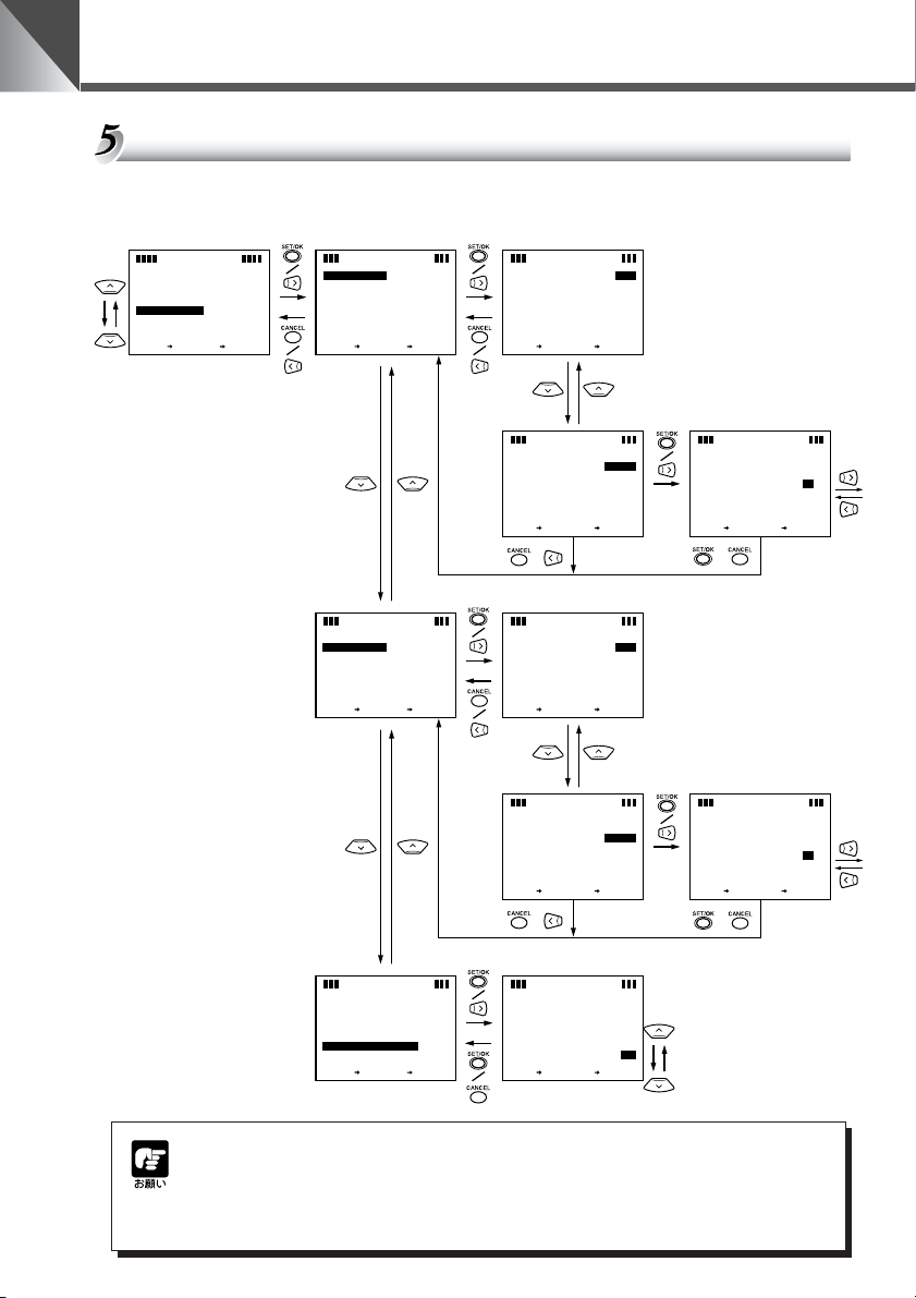
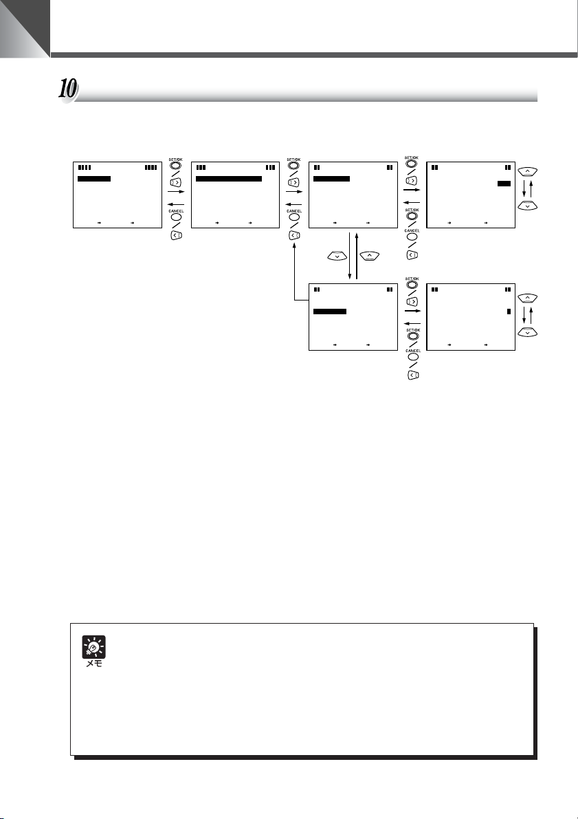
AE、フリッカ防止の設定
AE(明るさの調節)、およびフリッカ(画面のちらつき)防止を設定します。
M
MENU
E
S
T
P
LAY
I
S
D
C
M
A
E
R
A
E
X
N
TSET
AE
A
EREFERENCE
FLI CKE
R
E
X
N
TSET
AE
A
EREFERENCE
FLI CKE
R
E
X
N
TSET
NME
NU
A
I
MENU
MENU
A
C
B
KCA
N
NG
ESITT
D
LESS AETFF
A
C
B
N
KCA
NG
ESITT
D
LESS AETFF
A
C
B
N
KCA
M
AME
NU
E
R
AC
PA
N
SPEE
D
UTO
O
NNG
D
S
MIRROR
E
A
AUT
OD
..
O
O
FF
A
CEFFL
C
B
N
KCA
T
IT
L
SPEE
V
M
LE
ARANGEDEFAULT..
B
O
A
E
SETT I
DIR
ECTI
NIGHTO
M
E
X
N
CEL
TSET
A
E
FLI CKE
N
R
EFERENCE
E
X
TSET
NG
ESITT
AE
FAULT
D
E
R
LE
SS AE
FF
O
CEL
A
C
B
N
KCA
[5]が標準の明るさに相
当します(→ P.20)。
NG
ESITT
LUAFE
O
CEL
AE
A TLUAFE
EREFERENCE A TLUAFE
D
MANU
AL
CEL
CEL
CA
CA
N
N
SETSE T
EREFERENCE A
NG
ESITT
AE
D
MANU
AL
CEL
CEL
CA
N
N
CA
SETSE T
E
1-2-3-4-5-6-7-8-9-10
AE
R
EFERENCE
SETSE T
NG
ESITT
MANU
AL
CEL
CEL
CA
N
N
CA
/ /
NG
ESITT
LUAFE
O
CEL
AE
FLI CKERLESS AEFNO
CEL
N
N
CA
CA
SETSE T
O
CEL
防止します(→ P.35)。
[ON]に設定するとフリッカを
F
28
屋外での連続昼夜撮影など、光源が徐々に変化する場所で、被写体に変化が少な
い環境での撮影においては、映像が適切な色にならない場合があります。その場
合はパン・チルト・ズームなどを行うと適切な色になります。
Page 29
いろいろな設定
ナイトモードの設定
ナイトモードにすると、赤外光撮影により、暗闇でも白黒映像として被写体を確認できます。
ナイトモードに切り替えるとき、ナイトモード用の内蔵赤外光照明(赤外線 LED)が自動点
灯します。なお照明は、30 分後に自動消灯します。
M
M
E
NU
N
I
A
SET
M
E
NU
L
D
I
SP
AY
M
E
NU
M
C
E
URAA
EMN
CEL
A
E
C
B
KCA
N
X
N
TSET
AC
N
PA
SPEE
T
IT
L
SPEE
M
V
LE
ARANGEDEFAULT..
O
B
E
A
SETT I
DIR
ECTI
G
M
NH
E
X
N
TSET
M
AME
NU
E
R
D
UTO
A
D
AUT
O
NNG
S
..
O
MIRROR
O
FF
ETI
O
D
FOF
O
A
CEFFL
C
B
KCA
N
G
NH
M
ETI
O
D
● ナイトモードでは、オートフォーカスでピントが合いにくくなったり、ピントが合って
いないように見える場合があります。そのようなときは、マニュアルフォーカスでピン
トを合わせてください。
● ナイトモード状態において、リモコンでカメラを OFF にすると、内蔵赤外照明は消灯し
ますが、ナイトモードは保持されます。
この状態でリモコンにより再度カメラを ON にしても、内蔵赤外照明は点灯しません。
設定画面よりナイトモードを一旦 OFF にして、再度 ON すると、内蔵赤外照明が点灯
します。
● ナイトモード状態で電源を OFF にし、再度 ON にすると、ナイトモードは解除されま
す。
● RS-232C 制御(→ P.30)の場合、ナイトモードと内蔵赤外光照明は、別々に操作す
ることができます。また照明を 30 分以上点灯させることもできます。
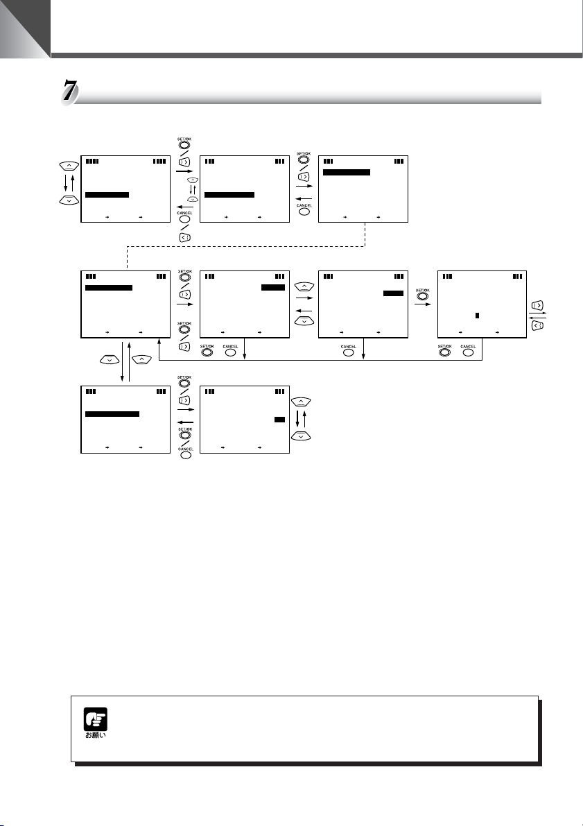
VC-C4 モードの場合の設定画面
本機は初期設定では VC-C4 モードになっています。
本機を VC-C3 モードで使用する場合は下記の設定画面が表示されます。
MAIN MENU画面 SET MENU 画面 CAMERA MENU画面 AE設定画面
M
NME
NU
A
I
MENU
E
S
T
C
M
A
MENU
E
A
R
A
CEL
C
E
B
X
KCA
N
TSET
N
T
S
E
S
32C ETT
S
R
-2
OON
TE C LLE I
EMO
R
O
M
M
C
N
D
A
R
ESTOREDEFAULT
E
X
N
TSET
M
E
NU
G
S
I
N
..
T
RR
A
C
B
KCA
D0
CEL
N
E3C-CVMOD
M
AME
NU
E
R
AC
PA
N
SPEE
D
UTO
T
IT
L
SPEE
E
A
SETT I
DIR
ECTI
E
X
N
TSET
A
AUT
OD
NNG
S
..
O
MIRROR
O
A
CEFFL
C
B
KCA
N
A
EREFERENCE
FLI CKE
E
X
N
TSET
NO
F
O
FOF
NG
ESITT
AE
D
R
LESS AETFF
A
C
B
KCA
日本語
LUAFE
O
CEL
N
モード変更後、s ボタンを押すと画面が一瞬消えますが、これは故障ではあり
ません。また、モードを変更するとプリセットはすべてクリアされ、カメラヘッ
ドの動作範囲も各モードの初期設定になります。
29
Page 30
いろいろな設定
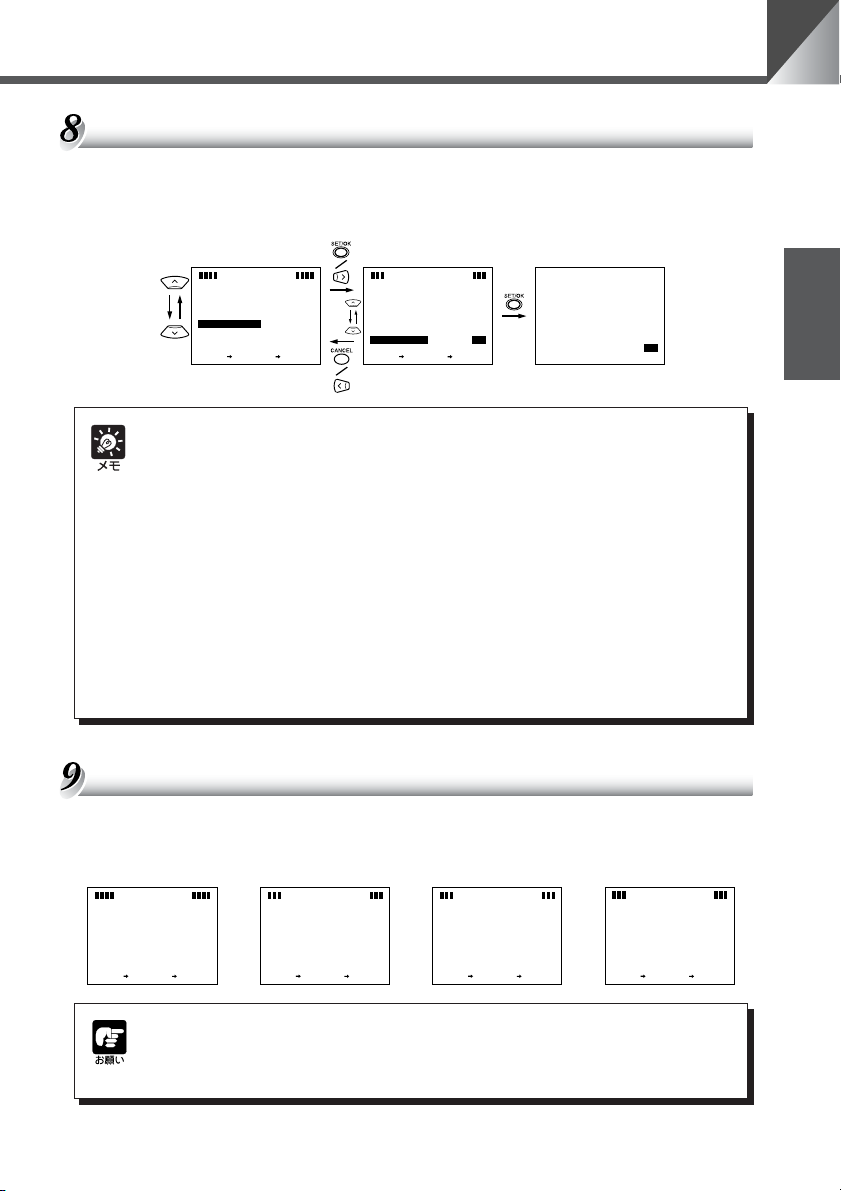
RS-232C の設定
本機をパソコンやその他の装置で制御するための設定です。DATA8BIT と NONPARITY
は設定値を確認するためのもので、固定です。
M
NME
NU
A
I
MENU
E
S
T
P
MENU
LAY
I
S
D
C
M
A
MENU
E
A
R
CEL
A
E
C
B
X
KCA
N
TSET
N
T
S
E
S
32C ETT
S
R
-2
OON
TE C LLE I
EMO
R
O
M
C
M
N
D
A
R
ESTOREDEFAULT
E
X
N
TSET
M
E
NU
G
I
S
N
..
T
RR
C
A
C
B
KCA
D0
CEL
N
E-C4VMOD
R
A
B
UD
P
T
O
S
D
AIT
A
T
NONPAR
E
X
N
R
A
B
UD
P
T
O
S
D
AIT
T
A
NONPAR
E
X
N
TTI
S-232
C
R
ATE 01069
TBI
8B
ITY
A
C
B
TSET
TTI
S-232
C
R
ATE 01069
TBI
8B
ITY
A
C
B
TSET
KCA
KCA
NG
SSE
NO
LYERA
D
NO
LYERA
D
CEL
N
NG
SSE
NO
LYERA
D
NO
LYERA
D
CEL
N
R
A
B
UD
R
P
T
O
S
S-232
R
SETSE T
S-232
SETSE T
NG
SSE
TTI
C
ATE
CA
C
TBI
CA
0
084
0069
00441
00291
CEL
CEL
CA
N
N
TTI
NG
SSE
1
2
CEL
CEL
CA
N
N
30
● SETMENU 画面の RS-232CSETTINGS 以外の項目については、以下を参照してく
ださい。
(1)REMOTECONTROLLERID の設定については 31 ページを参照してください。
(2)COMMAND は、本機をキヤノンコミュニケーションカメラ VC-C3 モードで使用す
るときに設定します(→ P.29)。
(3)RESTOREDEFAULT は工場出荷時の初期設定(→ P.36)に戻したいときに
[SET]を選択します。
Page 31

複数のカメラを個別に操作する
カメラ(VC-C50i または VC-C50iR)が複数台隣接して設置してある場合、リモコンで操作
をすると、受信したカメラはすべて一斉に同じ動作をします。このような場合、各カメラにあ
らかじめ ID 番号を設定しておくと、リモコンから ID 番号を指定することで個別にカメラを操
作することができます。
ID 番号を設定する
各カメラ(VC-C50i または VC-C50iR)それぞれに ID 番号(1 〜 9)を設定します。ID 番
号を設定しないときは[0]にします。隣接するカメラすべてに ID 番号を設定してください。ま
た、同じ ID 番号を複数のカメラに設定すると、それらは同一の動作をします。
1. ID 番号を設定するカメラだけ電源を ON にする。隣接す
るその他のカメラの電源は OFF にする
BRIGHT
ZOOM
T
W
電源の ON/OFF は、そのカメラに接続されている AC アダ
プタの電源プラグを抜き差ししてください(→ P.14)。電源
を OFF にしても ID 番号はクリアされません。
日本語
HOME
SET/OK CANCEL
AF
MF
∞
0
Fn
ON SCREEN
2. リモコンの m ボタンを押して MAINMENU 画面を表示
する
321
654
987
MENUID
3. SETMENU の REMOTECONTROLLERID を選択し、
ID 番号を設定する
上下にカーソルを移動するときは 58 ボタンで、設定し
て次の階層に進むときは s または 6 ボタンで、設定しない
で前の階層に戻るときは c または 4 ボタンを押します。
数値の変更は 58 ボタンを使用します。
NME
NU
A
I
M
MENU
E
S
T
P
MENU
I
LAY
S
D
C
M
A
MENU
E
R
A
AC
E
X
N
TSET
4.
設定したらmボタンまたはcボタンを押して画面を消す
CEL
B
KCA
N
E
T
S
32C ETT
S
S
R
-2
OON
EMO
TE C LLE I
R
M
C
M
N
D
O
A
R
ESTOREDEFAULT
E
X
N
TSET
E
T
S
32C ETT
S
S
R
-2
OON
TE C LLE I
EMO
R
M
C
M
N
D
O
A
R
ESTOREDEFAULT
E
X
N
TSET
M
E
NU
S
I
G
..
N
T
RR
-C4VC
AC
B
KCA
M
E
NU
I
S
G
..
N
T
RR
-C4VC
A
C
B
KCA
D0
CEL
N
D 0
CEL
N
EMOD
M
E
NU
E
T
S
T
RR
OON
TE C LLE I
EMO
EMOD
R
SET
SET
D 5
CEL
N
CA
CEL
CA
N
5. 1 〜 4 の操作を繰り返し、すべてのカメラに ID 番号を設
定する
31
Page 32

複数のカメラを個別に操作する
個別に操作したいカメラを選択する
<例> 下図のような 4 台のカメラ(ID1 〜 ID3)のうち、ID2(2 台)のカメラだけ個別に
操作できるようにします。通常の使用時は、カメラの LED は緑色で点灯しています。
BRIGHT
HOME
SET/OK CANCEL
AF
MF
∞
0
Fn
ON SCREEN
ID1
緑色で点灯
ID2
緑色で点灯
ID2
緑色で点灯
ID3
緑色で点灯
● 操作は、隣接するすべてのカメラの LED を確認しながら行ってください。リ
モコンの信号がすべてのカメラに届いているかどうか確認できます。
●
ID 番号が設定されていないカメラ(ID:0)は、ステップ 2 で ON になります。
● カメラが OFF のときでも、i ボタンを押すとすべてのカメラの LED はオレ
ンジ色に点滅して個別操作が開始できます。ただし、ステップ 2 で番号ボタ
ンを押したとき、ID 番号が一致しないカメラは OFF になります。
1.i ボタンを押す
ZOOM
MENUID
T
W
321
654
987
隣接するすべてのカメラの LED がオレンジ色の点滅(0.5
秒間隔)に変わります。
ID1
オレンジ色で点滅
ID2
オレンジ色で点滅
ID2
オレンジ色で点滅
ID3
オレンジ色で点滅
操作を中止したいときは c ボタンまたは i ボタンを押し
てください。すべてのカメラの LED が緑色の点灯に戻りま
す。
32
2. 番号ボタン(ここでは 2 )を押す
ID2 のカメラが選択され、そのカメラの LED だけが緑色の
点灯に変わります。その他のカメラの LED はオレンジ色の
(連続)点灯になります。
ID1
オレンジ色で点灯
ID2
緑色で点灯
ID2
緑色で点灯
以上で選択操作は終了です。リモコン操作をすると、選択されたカ
メラだけが動作します。リモコンのボタン操作中、選択されたカメ
ラの LED は緑色で点滅(0.1 秒間隔)し、選択されていないカメラ
の LED はオレンジ色の点滅(0.1 秒間隔)となります。
ID3
オレンジ色で点灯
Page 33

複数のカメラを個別に操作する
個別操作を解除する
<例> 前ページで選択した ID2 のカメラの個別操作を解除します。各カメラの LED は下図
のようになっています。
操作は、隣接するすべてのカメラの LED を確認しながら行ってください。リモ
コンの信号がすべてのカメラに届いているかどうか確認できます。
BRIGHT
HOME
SET/OK CANCEL
AF
MF
∞
0
Fn
ON SCREEN
ZOOM
MENUID
ID1
オレンジ色で点灯
ID2
緑色で点灯
ID2
緑色で点灯
ID3
オレンジ色で点灯
日本語
1.i ボタンを押す
T
W
321
654
987
隣接するすべてのカメラの LED がオレンジ色の点滅(0.5
秒間隔)に変わります。
ID1
オレンジ色で点滅
ID2
オレンジ色で点滅
ID2
オレンジ色で点滅
ID3
オレンジ色で点滅
操作を中止したいときは c ボタンまたは i ボタンを押し
てください。ID2 のカメラの LED は緑色の点灯に、その他
のカメラの LED はオレンジ色の点灯になります。
2.0 ボタンを押す
すべてのカメラの LED が通常の緑色の点灯となります。
ID1
ID2
ID2
ID3
緑色で点灯
緑色で点灯
緑色で点灯
緑色で点灯
以上で解除操作は終了です。すべてのカメラのリモコン操作が可能
になります。
33
Page 34

故障かなと思ったら
もう一度以下のことを確認してから販売店にご連絡ください。
リモコン操作ができない
確認 1. LED が消灯していませんか?
対処 電源プラグをコンセントに正しく奥まで差し込んでください。→ P.14
確認 2. LED が赤色で点灯していませんか?
対処 カメラが OFF になっています。リモコンのpボタンを押してカメラを
ON にしてください。→ P.22
確認 3. LED がオレンジ色で点灯をしていませんか?
対処 ID 設定機能による動作制限を受けています。ID を正しく設定し直すか、個
別操作を解除してください。→P.31〜33
確認 4. リモコンを操作したときに、LED が緑色で点滅していますか?
対処
確認 1. LED が赤色で点灯していませんか?
対処 カメラが OFF になっています。リモコンのpボタンを押してカメラを
・
リモコンの電池残量を確認してください。
・
リモコンの信号が届く範囲内で操作をしてください。→P.16
モニタに映像が映らない
ON にしてください。→ P.22
34
確認 2. 機器は正しく接続されていますか?
対処 機器を正しく接続してください。→ P.10 〜 11
確認 3. カメラとモニタの電源は ON になっていますか?
対処 カメラとモニタの電源を ON にしてください。→ P.14
カメラヘッドの向きがうまく変えられない
確認 1. カメラヘッドが動作範囲まで動きますか?
対処 何らかの原因でカメラヘッドが直接動いてしまいました。リモコンの
ボタンを押してください。→ P.17
確認 2. カメラヘッドの動作範囲を制限していませんか?
対処 動作範囲を変更してください。→ P.27
h
Page 35

故障かなと思ったら
プリセットで登録した位置にカメラヘッドが向かない
確認 1. カメラヘッドが動作範囲まで動きますか?
対処 何らかの原因でカメラヘッドが直接動いてしまいました。リモコンの
ボタンを押してください。→ P.17
確認 2. プリセット登録後にパン / チルトの動作範囲を変更していませんか?
対処 プリセットを登録し直してください。→ P.21
h
ピントが合わない
確認 1. マニュアルフォーカスになっていませんか?
対処 マニュアルでピントを調節するか、リモコンのaボタンを押してオート
フォーカスにしてください。→ P.19 〜 20
確認 2. レンズが汚れていませんか?
対処 レンズの清掃をしてください。→ P.7
確認 3. プリセットの実行をしましたか?
対処 マニュアルフォーカスの時にプリセットの実行をすると、実行後ピントが
合わない場合があります。マニュアルでピントを調節するか、リモコンの
a
ボタンを押してオートフォーカスにしてください。→P.19〜20
日本語
確認 4. 被写体とカメラの距離がピントの合う範囲からはずれていませんか?
対処 ズームの位置によってはオートフォーカス、マニュアルフォーカスにかか
わらず、ピントが合わない場合があります。カメラや被写体の位置を調節
してください。→ P.18
確認 5. オートフォーカスで、「オートフォーカスではピントの合いにくい被写体」
(→ P.19)で示すような被写体を映していませんか?
対処 マニュアルでピントを調節してください。→ P.20
画面がちらつく
確認 本機を電源周波数が 50Hz の地域でお使いですか?
対処 FLICKERLESSAE を ON にしてください。→ P.28
シャッタースピードを変更してちらつきを軽減します。
関東から東の電源周波数が 50Hz の地域では、蛍光灯で照明された室内で
は画面にちらつきが発生します。このような場合には、上記の操作でちら
つきをなくすことができます。中部から西の 60Hz の地域では、ちらつき
はありません。
35
Page 36

工場出荷時の初期設定
工場出荷時および RESTOREDEFAULT を[YES]にしたとき(→ P.30)、各項目は以下に
示す設定になります。
(本機の初期設定)
項 目 初期設定 項 目 初期設定
フォーカス * AUTO プリセット なし
ブライト * 標準の明るさ 時計および文字 非表示
(設定画面の初期設定)
項 目 初期設定
BAUDRATE 9600
STOPBIT 1
SETMENU
DISPLAYMENU
CAMERAMENU
DATA8BIT Readonly
NONPARITY Readonly
REMOTECONTROLLERID 0
COMMAND VC-C4MODE
DATEDISPLAY ON
TIMEDISPLAY ON
TXTDISPLAY ON
SETDATE * 01.JAN.’00
SETTIME * 00:00:00AM
TIMESTYLE * AM/PM
DATESTYLE * DD/MM/YY
設定した文字 * なし
PANSPEED AUTO(MANUAL は 10)
TILTSPEED AUTO(MANUAL は 10)
MOVABLERANGE DEFAULT
DIRECTIONMIRROR OFF
NIGHTMODE * OFF
AEREFERENCE DEFAULT(MANUAL は 5)
FLICKERLESSAE OFF
36
*印で示す項目は、電源を OFF から ON(→ P.14)にしたとき、工場出荷時の初期設定に
なります。それ以外の項目は、電源を OFF にしたときの値が保持されます。
Page 37

主な仕様
項 目 内 容
映像信号 NTSC 方式準拠
撮像素子 1/4 型 CCD
画素数 実効 34 万画素
同期方式 内部同期方式
水平解像度 460TV 本
垂直解像度 350TV 本
SN 比 50dB
走査方式 2:1 インターレス
最低被写体照度 ノーマルモード:1lux(1/30 秒時)/ナイトモード:0lux
撮像モード ノーマルモード/ナイトモード
駆動機構 VC-C50i パン機構 : 回転角度 左 100°右 100°、回転速度 1°〜 90°/ 秒※
VC-C50iR パン機構 : 回転角度 左 170°右 170°、回転速度 1°〜 90°/ 秒※
接続端子 出力端子 VIDEOOUT:BNC 型コンポジットビデオ出力
マルチコネクタ S-Video 出力、RS-232C 制御(入力、出力)、センサー入力、アラーム出力、外部照明制御
電源端子 DCIN定格13V
カスケード制御 最大 9 台
フォーカス オート / マニュアル W 端:0.01 m〜∞ / T端:1.6 m〜∞
絞り オートアイリスサーボ方式
レンズ f=3.5 〜 91.0mm F1.6 〜 4.0 電動 26 倍ズーム(無限遠撮影時)
赤外カットフィルタ 電動出し入れ(ノーマルモード/ナイトモード)
ナイトモード 赤外光照明 LED(4 灯)
レンズフィルタ径 37mm pitch=0.75mm
ホワイトバランス TTL 方式オート
消費電力 最大約 12.5W(専用 AC アダプタ含む)
使用環境 温度:0℃〜 40℃ 湿度:20% 〜 85%RH(結露なきこと)
設置角度 水平に対して± 20°(オプションのワイドコンバータ使用時は± 15°)
本体サイズ VC-C50i:100mm(W)× 117mm(D)× 96mm(H)(突起物は含まず)
本体質量 VC-C50i:約 420g/VC-C50iR:約 490g
リモコン 型式 WL-V5
(オプション) 方式 赤外線パルス方式
電源 DC3V(単 3 乾電池× 2)
サイズ 50mm(W)× 175mm(D)× 24.5mm(H)(突起物は含まず)
質量 約 79g(電池は含まず)
AC アダプタ 型式 PA-V16
入力 AC100ー 240V 50/60Hz 50ー 65VA
出力 DC13V 1.8A(max.)
極性 外側(ー) 内側(+)
サイズ 58mm(W)× 118mm(D)× 25mm(H)(突起物は含まず)
質量 約 205g(ケーブル含まず)
(ナイトモード時W端:0.02m 〜∞ / T端:2.3m 〜∞)
照明投射可能距離 3m
VC-C50iR:100mm(W)× 117mm(D)× 97.6mm(H)(突起物は含まず)
※ 本機をコンピュータで制御し、低速でカメラヘッドを駆動させた場合、映像がゆれることがあります。
● 仕様は改善などの理由で予告なく変更することがあります。
●ACアダプタは、必ず付属の専用 AC アダプタを使用してください。また、付属の AC アダプタは、本製品以
外には使用しないでください。
チルト機構: 回転角度 上 90°(工場出荷時は 30°)下 30°、
チルト機構: 回転角度 上 10°下 90°、回転速度 1°〜 70°/ 秒※
回転速度 1°〜 70°/ 秒※
日本語
37
Page 38

お問い合せ先
製品に関するお問い合せは、お客様相談センターをご利用ください。
キヤノンお客様相談センター
TV 会議システム・ビジュアルコミュニケーション
050-555-90074
[受付時間]
<平日> 9:00 〜 12:00 / 13:00 〜 17:00
(土・日・祝日及び年末年始弊社休業日は休ませていただきます)
※ 上記番号をご利用いただけない方は043-211-9622をご利用ください。
※IP電話をご利用の場合、プロバイダーのサービスによってつながらない場
合があります。
※ 受付時間は予告なく変更する場合があります。あらかじめご了承ください。
補修用性能部品について
保守サービスのために必要な保守用性能部品の最低保有期間は、製品の製造打
ち切り後 7 年間です。
(補修用性能部品とは、その製品の機能を維持するために必要な部品です)
Page 39

INSTRUCTION MANUAL
ENGLISH
ENGLISH
Page 40

Introduction
Thank you for purchasing the Canon Communication Camera VC-C50i/VC-C50iR.
Please read this Instruction Manual carefully to ensure that you use the Product
correctly and safely. Read the “a Safe Use of Equipment” section first and
observe these instructions when you use the Product.
Features of the VC-C50i/VC-C50iR Communication Camera
■ Genuine Canon 26× optical zoom and 12× digital zoom for high-
magnification imaging
■ Capable of shooting at low light levels down to 1 lux
■ Built-in infrared light allows shooting even at 0 lux (Night mode)
■ High-speed high-precision camera head movement
■ Noise reduction circuitry for crystal clear images
2
Page 41

Introduction
Notice
This product uses a microcomputer. External radio frequency energy, may cause
picture interference, avoid using this product in such a location.
Exclusion of Liability
If the Product is connected to a recording device (for example a VCR), Canon
Inc. accepts no responsibility whatsoever for any financial losses that may be
incurred as a result of the loss of recorded information or images, regardless of
the internal or external cause of the loss.
Copyright Information
Video or still images recorded using your VC-C50i/VC-C50iR cannot be used in
ways that infringe copyright laws or without the consent of the owner, unless
intended for personal use only.
Note
The contents of this Manual are subject to change without notice.
CANON and the CANON logo are registered trademarks of Canon Inc. Other
names of products and companies mentioned in this Manual are trademarks or
registered trademarks of the respective companies.
© Copyright 2003 CANON INC.
ALL RIGHTS RESERVED
ENGLISH
3
Page 42

a Safe Use of Equipment
An exclamation point, within a triangle, is intended to alert the user to the presence of
important operating and maintenance (servicing) instructions in the literature
a
accompanying the equipment.
a Important Warnings
a CAUTION:
TO REDUCE THE RISK OF ELECTRIC SHOCK, DO NOT REMOVE COVERS.
NO USER-SERVICEABLE PARTS INSIDE. REFER SERVICING TO
QUALIFIED SERVICE PERSONNEL.
The serial number of this equipment may be found on the back of the camera
head. No others have the same serial number as yours.
You should record the number and other vital information here and retain this
book as a permanent record of your purchase to aid identification in case of
theft.
Date of Purchase
Dealer Purchased from
Dealer Address
Dealer Phone No.
Model No. VC-C50i or VC-C50iR
Serial No.
For Users in the UK (PA-V16)
When replacing the fuse only a correctly rated approved type should be used
and be sure to re-fit the fuse cover.
The AC adapter can be connected to the VC-C50i/VC-C50iR from a standard AC
power outlet. Please check your instruction manual to make sure that your
VC-C50i/VC-C50iR is compatible with this adapter.
– The socket-outlet should be installed near the equipment and should be easily
accessible.
– Unplug the apparatus from the wall outlet before cleaning or maintaining.
4
Page 43

a
Safe Use of Equipment
a Important Operational Instructions
a WARNING:
TO REDUCE THE RISK OF ELECTRIC SHOCK, DO NOT EXPOSE THIS
EQUIPMENT TO RAIN OR MOISTURE.
a CAUTION:
TO REDUCE THE RISK OF ELECTRIC SHOCK AND TO REDUCE ANNOYING
INTERFERENCE, USE THE RECOMMENDED ACCESSORIES ONLY.
FDA regulation
This equipment has not been evaluated by the Food and Drug Administration
(FDA) for use as a medical device. When incorporated into a system with
medical applications, FDA regulations may apply. Consult your legal advisor to
determine whether FDA regulations apply.
European Union (and EEA) only.
This symbol indicates that this product is not to be disposed of with
your household waste, according to the WEEE Directive (2002/96/
EC) and your national law. This product should be handed over to a
designated collection point, e.g., on an authorized one-for-one basis
when you buy a new similar product or to an authorized collection site
for recycling waste electrical and electronic equipment (EEE).
Improper handling of this type of waste could have a possible
negative impact on the environment and human health due to
potentially hazardous substances that are generally associated with
EEE. At the same time, your cooperation in the correct disposal of
this product will contribute to the effective usage of natural resources.
For more information about where you can drop off your waste
equipment for recycling, please contact your local city office, waste
authority, approved WEEE scheme or your household waste disposal
service.
Your cooperation in the correct disposal of this product will contribute
to the effective usage of natural resources and will avoid incurring
administrative sanctions according to art.
50 and following of Italian legislative decree 22/97.
For more information regarding return and recycling of WEEE
products, please visit
www.canon-europe.com/environment.
ENGLISH
(EEA: Norway, Iceland and Liechtenstein)
5
Page 44

a
Safe Use of Equipment
FCC NOTICE
COMMUNICATION CAMERA, Model: PT-50iN/PT-50iNR/PT-50iP/PT-50iPR
This device complies with Part 15 of the FCC Rules. Operation is subject to the
following two conditions: (1) This device may not cause harmful interference,
and (2) this device must accept any interference received, including interference
that may cause undesired operation.
Note: This equipment has been tested and found to comply with the limits for a
Class B digital device, pursuant to Part 15 of the FCC Rules. These limits are
designed to provide reasonable protection against harmful interference in a
residential installation. This equipment generates, uses and can radiate radio
frequency energy and, if not installed and used in accordance with the
instructions, may cause harmful interference to radio communications.
However, there is no guarantee that interference will not occur in a particular
installation. If this equipment does cause harmful interference to radio or
television reception, which can be determined by turning the equipment off and
on, the user is encouraged to try to correct the interference by one or more of
the following measures:
- Reorient or relocate the receiving antenna.
- Increase the separation between the equipment and receiver.
- Connect the equipment into an outlet on a circuit different from that to which
the receiver is connected.
- Consult the dealer or an experienced radio/TV technician for help.
Use of shielded cable is required to comply with class B limits in Subpart B of
Part 15 of FCC Rules.
Do not make any changes or modifications to the equipment unless otherwise
specified in the manual. If such changes or modifications should be made, you
could be required to stop operation of the equipment.
Canon U.S.A. Inc.
One Canon Plaza, Lake Success, NY 11042, U.S.A.
Tel No. (516) 328-5600
IC NOTICE
This product does not exceed the Class B limits for radio noise emissions from
digital apparatus as set out in the Interference-causing equipment standard
entitled ‘Digital Apparatus’, ICES-003 of the Industry Canada.
6
Page 45

a IMPORTANT SAFETY INSTRUCTIONS
a
Safe Use of Equipment
In these safety instructions, the word
“equipment” refers to the Canon
communication camera VC-C50i/VC-C50iR
and all its accessories.
1. Read Instructions - All the safety and
operating instructions should be read
before the equipment is operated.
2. Retain Instructions - The safety and
operating instruction should be retained
for future reference.
3. Heed Warnings - All warnings on the
equipment and in the operating
instructions should be adhered to.
4. Follow Instructions - All operating and
maintenance instructions should be
followed.
5. Cleaning - Unplug this equipment from
the wall outlet before cleaning.
Wipe the equipment with a clean soft
cloth. If necessary, put a cloth in diluted
neutral detergent and wring it well
before wiping the equipment with it.
Finally, clean the equipment with a
clean dry cloth. Do not use benzene,
thinner or other volatile liquids or
pesticides as they may damage the
product’s finish. When using chemicallytreated cleaning cloths, observe those
precautions accordingly.
6. Accessories - Do not use accessories
not recommended in this manual as
they may be hazardous. Always use
specified connection cables. Connect
devices correctly.
7. Water and Moisture - Hazard of electric
shock - Do not use the equipment near
water or in rainy/moist situations. Do
not put a heater near this equipment.
8. Placing or Moving Do not place on an
unstable cart, stand,
tripod, bracket or
table. The equipment
may fall, causing
serious injury to a child or adult, and
serious damage to the equipment. An
equipment and cart combination should
be moved with care. Quick stops,
excessive force, and uneven surfaces
may cause the equipment and cart
combination to overturn.
9. Power Sources - The PA-V16 AC
adapter should be operated only from
the type of power source indicated on
the marking label. If you are not sure of
the type of power supply to your home,
consult your equipment dealer or local
power company.
10. Polarization - The PA-V16 AC adapter
is equipped with a polarized 2-prong
plug (a plug having one blade wider
than the other).
The 2-prong polarized plug will fit into
the power outlet only one way. This is a
safety feature. If you are unable to
insert the plug fully into the outlet, try
reversing the plug. If the plug still fails
to fit, contact your electrician to replace
your obsolete outlet. Do not defeat the
safety purpose of the polarized plug.
11. Power Cord Protection - Power cords
should be routed so that they are not
likely to be walked on or pinched by
items placed upon or against them. Pay
particular attention to plugs and the
point from which the cords exit the
equipment.
12. Outdoor Antenna Grounding - If an
outside antenna is connected to the
equipment, be sure the antenna is
grounded so as to provide some
protection against voltage surges and
built-up static charges. Section 810 of
the National Electrical Code, ANSI/
NFPA No.70-1984, provides
information with respect to proper
grounding of the mast and supporting
structure, grounding of the lead-in wire
to an antenna discharge unit, size of
grounding conductors, location of
ENGLISH
7
Page 46

a
Safe Use of Equipment
antenna discharge unit, connection to
grounding electrodes, and requirements
for the grounding electrode. See figure
1.
fig-1
EXAMPLE OF ANTENNA GROUNDING AS
PER NATIONAL ELECTRICAL CODE
ANTENNA LEAD
IN WIRE
GROUNDING
CLAMP
ELECTRIC
SERVICE
EQUIPMENT
NEC — NATIONAL ELECTRIC CODE
ANTENNA
DISCHARGE
UNIT (NEC
SECTION 810-20)
GROUNDING
CONDUCTORS
(NEC SECTION
810-21)
GROUNDING CLAMPS
POWER SERVICE
GROUNDING ELECTRODE
SYSTEM
(NEC ART 250. PART H)
13. Lightning - For added protection of this
equipment during a lightning storm, or
when it is left unattended and unused
for long periods of time, disconnect it
from the wall outlet and disconnect the
antenna. This will prevent damage to
the equipment due to lightning and
power-line surges.
14. Power Lines - An outside antenna
system should not be located in the
vicinity of overhead power lines or other
electric light or power circuits, or where
it can fall into such power lines or
circuits. When installing an outside
antenna system, extreme care should
be taken to keep from touching such
power lines or circuits as contact with
them might be fatal.
15. Overloading - Do not overload wall
outlets and extension cords as this can
result in a risk of fire or electric shock.
16. Object and Liquid Entry - Never push
objects of any kind into this equipment
through openings as they may touch
dangerous voltage points or short out
parts that could result in a fire or
electric shock. Be careful not to spill
liquid of any kind onto the equipment.
17. Servicing - Do not attempt to service
this equipment yourself as opening or
removing covers may expose you to
dangerous voltage or other hazards.
Refer all servicing to qualified
personnel.
18. Damage Requiring Service Disconnect this equipment from the wall
outlet and all power sources including
batteries, and refer servicing to
qualified service personnel under the
following conditions.
a. When the power-supply cord or plug
is damaged.
b. If any liquid has been spilled onto, or
objects have fallen into, the
equipment.
c. If the equipment has been exposed
to rain or water.
d. If the equipment does not operate
normally even if you follow the
operating instructions. Adjust only
those controls that are covered by
the operation instructions. Improper
adjustment of other controls may
result in damage and will often
require extensive work by a qualified
technician to restore the equipment
to its normal operation.
e. If the equipment has been dropped
or the cabinet has been damaged.
f. When the equipment exhibits a
distinct change in performance. This
indicates a need for service.
19. Replacement Parts - When
replacement parts are required, be sure
the service technician has used
replacement parts that are specified by
Canon or that have the same
characteristics as the original part.
Unauthorized substitutions may result
in fire, electric shock or other hazards.
8
Page 47

a
Safe Use of Equipment
20. Safety Check - Upon completion of any
service or repairs to this equipment, ask
the service technician to perform safety
checks to determine that the equipment
is in safe operating order.
21. Do not install the equipment in the
following locations as this can cause a
fire or electric shock:
- Hot locations
-Close to a fire
- Very humid or dusty locations
- Locations exposed to direct sunlight
- Locations exposed to salt spray
- Close to flammable solvents (alcohol,
thinners, etc.)
22. When any of the following occurs,
immediately switch OFF the equipment,
unplug it from the main power supply
and contact your nearest Canon
supplier. Do not continue to use the
equipment as this can cause a fire or
electric shock.
- The equipment emits any smoke,
heat, abnormal noise, or unusual
odor.
-A metal object falls into the
equipment.
- The equipment is damaged in some
way.
23. Please observe the following when
using the equipment. Failure to do so
can result in a fire or electric shock.
- Do not use flammable sprays near
the equipment.
- Do not subject the equipment to
strong impacts.
24. Please observe the following when
handling the batteries. Failure to do so
can result in the batteries bursting or
emitting heat, sparks or corrosive fluid.
- Do not throw the batteries into a fire,
and do not heat, short-circuit or
attempt to disassemble the batteries.
- Do not attempt to recharge the
batteries.
- Do not use batteries other than those
specified for use with the equipment.
25. Please observe the following when
handling the batteries. Failure to do so
may result in the batteries bursting or
emitting heat, sparks or corrosive fluid.
- When the batteries are used up, or
when the equipment will not be used
for an extended period, remove the
batteries.
- When replacing the batteries, always
replace both batteries, and do not
use different types of batteries
together.
- Ensure that the + and – terminals are
correctly positioned when you load
the batteries.
- If any soiling or leakage of the
internal battery fluid occurs,
thoroughly clean the soiling or leaked
fluid with water.
ENGLISH
9
Page 48

a
Safe Use of Equipment
Maintenance
Cleaning the Equipment
1. Unplug the AC adapter from the wall outlet.
2. Carefully wipe the equipment with a soft cloth that has been moistened
with water or a mild detergent.
a
WARNING
Do not use flammable solvents such as alcohol, benzene or thinners.
The use of such substances can cause a fire or electric shock.
3. Wipe with a dry cloth.
4. When you have finished, plug the AC adapter back in to
the wall outlet.
Cleaning the Lens
Use a commercially available lens cleaner to remove any soiling from the
lens.
■ The auto-focus may not function correctly if the surface of the lens is dirty.
■ Scratches on the surface of the lens will cause image defects.
10
Icons Used in This Instruction Manual
WARNING Represents instructions that, if ignored, could result in death or
a
NOTE
MEMO
serious personal injury caused by incorrect operation of
equipment. Instructions indicated by this icon must be observed
for safe operation.
Indicates important information that must be observed or actions
that are prohibited during an operation. These notes must be
read to prevent possible faults or damage to the equipment.
Indicates supplementary information or a reference to an
operation. Users are advised to read these memos.
Page 49

CONTENTS
a Safe Use of Equipment .......................................................................................... 4
a Important Warnings ................................................................................... 4
a Important Operational Instructions .......................................................... 5
a IMPORTANT SAFETY INSTRUCTIONS ..................................................... 7
Maintenance .................................................................................................. 10
Icons Used in This Instruction Manual............................................................. 10
Before You Use the Product .................................................................................... 12
Checking the Camera and Its Accessories................................................. 12
Nomenclature ................................................................................................ 12
Installing the Product ................................................................................... 13
Connecting the Components ....................................................................... 14
Turning the Power ON and OFF................................................................... 18
LED Displays and the Camera Status ....................................................................... 18
Controlling the Camera from the Wireless Controller ........................................... 19
Nomenclature ................................................................................................ 19
Loading the Batteries into the Wireless Controller ................................... 20
Operable Range of the Wireless Controller ............................................................... 20
Changing the Camera Head Angle (pan/tilt/home position) ..................... 21
Range of Camera Head Movement ........................................................................... 21
Zooming In/Out (TELE/WIDE) ....................................................................... 22
Focusing (FOCUS) ........................................................................................ 23
Adjusting the Brightness (BRIGHT) ............................................................ 24
Storing a Preset Camera Position (PRESET) ............................................. 25
Switching the Camera ON and OFF............................................................. 26
ENGLISH
Camera Settings ....................................................................................................... 27
Buttons Used to Specify the Settings ......................................................... 27
Setting Menu Description .......................................................................................... 27
Setting the Clock ........................................................................................... 28
Entering Characters ...................................................................................... 29
Selecting Display/Hide Clock and Text ....................................................... 29
Setting the Camera Head Movement Speed and Pan Operation ....................
Setting the Range of Camera Head Movement .......................................... 31
Setting the AE................................................................................................ 32
Night Mode Settings .................................................................................... 33
VC-C4 Mode Setting Menu .......................................................................... 33
RS-232C Settings .......................................................................................... 34
ID Mode ...................................................................................................................... 35
Setting the ID Number .................................................................................. 35
Selecting the Camera to be Controlled ....................................................... 36
Cancelling ID Mode ....................................................................................... 37
Troubleshooting ........................................................................................................ 38
Factory Default Settings ........................................................................................... 40
Specifications ............................................................................................................ 41
30
11
Page 50

Before You Use the Product
Checking the Camera and Its Accessories
Before you install the Product, check that all the items shown below are included in your
product package. If any of these items is missing, contact your Canon dealer.
or
VC-C50i camera VC-C50iR camera
Multiconnector
Plug
● Instruction Manual
● Warranty Card (NTSC model only)
Nomenclature
VC-C50i VC-C50iR
Camera head
(→ P.21)
Base (→ P.13)
Infrared light window
(→ P.33)
LED (→ P.18)
Wireless controller
sensor (→ P.20)
AC adapter PA-V16
(NTSC model only)
■ Optional Product
● Wireless Controller WL-V5 (→ P.19)
● Wide-angle Converter WL-37 (→ P.14)
Cannot be used on the VC-C50iR.
(Front)
(Rear)
AC cable
(NTSC model only)
Wireless controller
sensor (→ P.20)
LED (→ P.18)
Base (→ P.13)
Camera head
(→ P.21)
Infrared light
window (→ P.33)
Multiconnector
(→ P.14)
DC IN 13V terminal
(→ P.14)
VIDEO OUT terminal
(→ P.14)
12
DC IN 13V terminal (→ P.14)
VIDEO OUT terminal (→ P.14)
Multiconnector (→ P.14)
* The screw mount for a tripod is located in the center of the underside of the camera.
Page 51

Installing the Product
Before You Use the Product
VC-C50i Installation
Install in a flat and stable location.
Mounting plate
(Installation)
• Distance between tapped holes: 114 mm (4.49 in.)
• Tapped hole diameter: 6 mm (0.24 in.)
• Mounting plate thickness: 1 mm (0.04 in.)
a
WARNING
Install the camera securely.
● When installing the camera on the ceiling, contact your Canon dealer.
● When installing the camera on the ceiling, check that the ceiling is strong enough to
bear the weight of the camera including the installation bracket. Installation in a
weak location could result in the camera falling and causing serious injury.
● At least once a year, check for looseness in the camera installation mount. (If the
optional wide-angle converter is used, check the converter mount also.)
* The Wide-angle Converter WL-37 cannot be used on the VC-C50iR.
The permissible camera installation angles are ±20° from the horizontal. (±15°
when the optional wide-angle converter is used.)
NOTE
Firmly tighten the 2 screws (not supplied).
Screw
VC-C50iR Installation
VC-C50iR
Screw
ENGLISH
Using a Tripod
The screw mount for a tripod is located in the center of the underside of the camera.
● Do not overtighten the mounting screw.
NOTE
If excessive force is used to tighten the
mounting screw, camera head movement
may be impeded, or other malfunctions may
result.
● Always use a tripod mounting screw that is
less than 6.0 mm (0.24 in.) in length. The use
of screws 6.0 mm (0.24 in.) long or longer
could damage the camera. Also, the tripod
seat used should be at least 30 mm (1.18 in.)
in diameter.
30 mm
(1.18 in.)
or wider
Less than
6.0 mm
(0.24 in.)
Mounting
screw
13
Page 52

Before You Use the Product
Using the Wide-angle Converter
The optional Wide-angle Converter WL-37 can be used to provide wide-angle shots (approx.
0.74× the normal focal distance).
Mount the wide-angle converter correctly so that it is level and fitted securely onto the
camera. When mounted correctly, the wide-angle converter should turn roughly 3 times before
stopping.
Wide-angle Converter
a
WARNING
The Wide-angle Converter WL-37 cannot be used on the VC-C50iR. If the converter
is used on the VC-C50iR, the mount will gradually loosen and the converter will fall off
the camera.
● The camera may not operate correctly if a wide-angle converter other than
NOTE
the WL-37 is used.
● If you use the optional Wide-angle Converter WL-37, set the zoom lens to the
wide-angle end. If you set the zoom lens to the telephoto end, the image
resolution will be affected and the autofocus might have problems.
● The permissible range of camera installation angles with the wide-angle
converter mounted on the camera is ±15° from the horizontal.
● The wide-angle converter cannot be used in night mode. (→ P.33)
14
Connecting the Components
B1
B10
AC cable
AC Adapter
VIDEO OUT A1
DC IN 13V
BNC connector
A10
Multiconnector plug
(Rear of camera)
To VIDEO IN terminal
• PC
• Another
VC-C50i/
VC-C50iR
• Network
camera server
• Sensor
• Alarm
• Monitor
Monitor
Page 53

Connecting to the Multiconnector
A
10
B
1
B
10
A
10
B
1
B
10
Use the procedure below to plug leads (AWG No.28-18) into
the multiconnector plug.
1. Insert a flat-bladed screwdriver all the way into
the slot next to the lead fastening hole.
■ The inside of the lead fastening hole opens.
2. With the screwdriver still inserted, push the end
of the lead into the lead fastening hole.
3. Holding the lead securely so that it does not
come out of the lead fastening hole, pull out the
screwdriver.
■ The lead is secured inside the lead fastening hole.
Use the same procedure to connect all the required leads.
Before You Use the Product
Lead
ENGLISH
Attaching the Multiconnector to the Camera
1. Raise the levers on each side of the
multiconnector plug.
2. Push the multiconnector plug into the
multiconnector socket.
3. Push the multiconnector plug in fully.
■ The multiconnector plug is locked into the
socket on the rear of the camera.
To remove the multiconnector, push the levers on both sides
downwards at the same time.
B1
B10
A10
15
Page 54

Before You Use the Product
Multiconnector Pin Layout
B1
A1
B10
A10
A1 Y GND Y OUT B1
A2 C GND C OUT B2
A3 RTS OUT CTS OUT B3
A4 TX OUT RX OUT B4
A5 GND GND B5
A6 RTS IN CTS IN B6
A7 TX IN RX IN B7
A8 Light_ON/OFF- Light_ON/OFF+ B8
A9 Alarm_- Alarm_+ B9
A10 Sensor_- Sensor_+ B10
Item
S-video out
RS-232C
(connects to
cascadeconnection
camera)
RS-232C
(connects to
cascadeconnection
PCs)
Pin No.
A1 Y GND Output ⇒ MONITOR
B1 Y OUT Output ⇒ MONITOR S-video luminance output
A2 C GND Output ⇒ MONITOR
B2 C OUT Output ⇒ MONITOR S-video chroma output
A3 RTS Output ⇒ NEXT CAMERA
B3 CTS Input NEXT CAMERA ⇒
A4 TXD Output ⇒ NEXT CAMERA
B4 RXD Input NEXT CAMERA ⇒
A5 GND – –
B5 GND – – RS-232C input GND
A6 RTS Output ⇒ PC
B6 CTS Input PC ⇒
A7 TXD Output ⇒ PC RS-232C input send data
B7 RXD Input PC ⇒
Pin name Signal direction Notes
Input/
Output
S-video luminance output
GND
S-video chroma output
GND
RS-232C cascade output
send request
RS-232C cascade output
send enabled
RS-232C cascade output
send data
RS-232C cascade output
receive data
RS-232C cascade output
GND
RS-232C input send
request
RS-232C input send
enabled
RS-232C input receive
data
16
Page 55

Before You Use the Product
Item
External lighting
control signal
Alarm control
signal
External sensor
input
Pin No.
A8 Light_ON/OFF- Output Current input
B8 Light_ON/OFF+ Output Current output
A9 Alarm_- Output Current input
B9 Alarm_+ Output Current output
A10 Sensor_- Input Current input GND
B10 Sensor_+ Input Current output
Pin name Signal direction Notes
Input/
Output
External lighting switch
50V/200mA (max.)
External lighting switch
50V/200mA (max.)
Alarm control 50V/
200mA (max.)
Alarm control 50V/
200mA (max.)
Pull-up to 5V, diode
protected
External Device I/O Terminals
External device input terminals
These comprise 2 sensor terminals (positive (+) and negative (–)). The negative terminal is
connected to the camera’s own internal ground and the positive terminal is pulled up to 5 volts
at 10 kohm via a protection diode. Connecting the respective leads to the positive and
negative terminals and then shorting across the terminals (ON) or not (OFF) generates an
interrupt for the internal controller. The power supplies and grounds for connected sensors
and switches should be connected to electrically segregated terminals. When an ON state is
detected, an event occurrence is posted to the host PC.
External device output terminals
These comprise ON and OFF terminals for the alarm and light terminals, with equivalent
terminals in both directions for the respective combinations. The two terminals can be
switched between conductive and resistive states using the internal controller. In addition, an
optical connector is used in the output terminal and is separate from the internal circuits in the
camera.
The load connected to the output terminal should be within the following ratings:
Rated values between output terminals
Max. DC voltage: 50V
Continuous load current: 120 mA
ENGLISH
Item
Pin No.
Pin name Signal direction Notes
17
Page 56

Before You Use the Product
Turning the Power ON and OFF
The VC-C50i/VC-C50iR camera does not have a power switch. You can switch the camera on
by plugging the AC adapter into a wall outlet. When power to the camera is switched on, the
LED on the camera turns green. If the monitor is switched on, an image appears on the
screen.
to AC outlet
Camera
Monitor
AC cable
AC adapter
● Whenever you turn the camera on, the first use of the PC or wireless
NOTE
controller to control the camera initializes the camera head position.
(Initialization takes several seconds.) The LED on the camera flashes
green (at 1-second intervals) during initialization.
● Never touch the camera head during initialization. This could prevent
successful initialization and cause faults.
● Wait at least five seconds before turning the power back on after shutting it
off. Turning it on too quickly may result in a malfunction. Observe the
precautions given in “a Safe Use of Equipment/a IMPORTANT SAFETY
INSTRUCTIONS” (→ P.7–9).
LED Displays and the Camera Status
LED Display Camera Status
Green Camera is on. (→ P.26)
At 0.1-sec. intervals Wireless controller button being used.
Blinking green At 0.5-sec. intervals
At 1-sec. intervals Camera head position initialization in progress.
Orange
At 0.1-sec. intervals
Blinking orange
At 0.5-sec. intervals
Red Camera is off. (→ P.26)
Off Power is off. (Power is not connected to the camera.)
Storing or restoring a preset (→ P.25), or displaying
a setting menu. (→ P.27)
Individual camera operation in progress and this camera
is not selected. (→ P.36)
Camera is not selected for individual operation and is
being controlled from the wireless controller. (→ P.36)
The camera is being selected or deselected for
individual operation. (→ P.36)
18
Page 57

Controlling the Camera from the Wireless Controller
The Wireless Controller WL-V5 is optional.
While the wireless controller buttons are being used, the LED on the camera blinks green (at
0.1-second intervals).
Nomenclature
Camera ON/OFF button (→ P.26)
Switches the camera on and off.
BRIGHT button (→ P.24)
Adjusts the brightness of the
image on the monitor.
• + : Brightens the image.
• – :Darkens the image.
SET/OK button (→ P.25, 27, 35)
Used to store preset positions.
Can also be used to proceed to
the next level when specifying
settings in a setting menu.
FOCUS button (→ P.23, 24)
Adjusts the focus.
•AF:Switches to auto-focus.
•MF:Focus is fixed.
• ▲ : Lengthens the focal
distance.
• ▼ : Shortens the focal
distance.
ON SCREEN button (→ P.27, 29)
Displays or hides the date, time
and text.
Fn button
Not used.
BRIGHT
HOME
SET/OK CANCEL
AF
MF
∞
0
Fn
ON SCREEN
WL-V5
WIRELESS CONTROLLER
ZOOM
T
W
321
654
987
MENUID
ZOOM button (→ P.22)
Increases or decreases the size of the
subject on the monitor screen.
• T : Enlarges the subject (zoom in).
• W :Shrinks the subject (zoom out).
Camera control button (→ P.21, 27, 35)
Used to change the camera head angle
and to move the on-screen cursor.
V
< >
: Move the camera head up,
•
^
down, left and right
• HOME : Moves the camera head to the
CANCEL button (→ P.25, 27, 35)
Cancels registration of a preset camera
position. Also cancels a setting selected
in a setting menu and returns you to the
previous level.
Number buttons (→ P.25, 36, 37)
Used to store and restore preset
positions, and to select the camera when
multiple cameras are used. The * and
# buttons are not used.
MENU button (→ P.27, 35)
Used to display and exit the MAIN
MENU.
ID button (→P.36, 37)
Used to control multiple cameras
individually. When the cameras are
switched off, pressing this button begins
individual camera control.
respectively.
center.
ENGLISH
Battery cover
See P.20 for information on
loading the batteries.
Whenever possible, switch the camera off when it is not in use (→ P.26) as this
reduces power consumption. If the camera will not be used for an extended
MEMO
period, unplug the AC adapter from the wall outlet (→ P.18). If you turn the
power off, the date and time will be cleared.
19
Page 58

Controlling the Camera from the Wireless Controller
Loading the Batteries into the Wireless Controller
The wireless controller requires two AA-type batteries.
1. Remove the battery cover.
2. Insert the batteries.
■ Taking care that the poles (+ and –) are
correctly positioned.
3. Replace the battery cover.
20
a
WARNING
Observe the following precautions when handling batteries.
Failure to do so could result in the batteries bursting or emitting heat, sparks or
corrosive fluid.
● Do not throw the batteries into a fire, and do not heat, short-circuit or attempt
to disassemble the batteries.
● Do not attempt to recharge the batteries.
Operable Range of the Wireless Controller
Use the wireless controller within the range described below, facing it toward the sensor for
the wireless controller. The operable range of the wireless controller varies depending on the
amount of charge remaining in the batteries and interference from other objects. (This applies
equally to the VC-C50iR.)
5 m
(16.4 ft.)
30°
90°
90°
30°
Page 59

Controlling the Camera from the Wireless Controller
Changing the Camera Head Angle (pan/tilt/home position)
Use the procedures below to change the camera head angle.
To move the camera head left and right (pan)
BRIGHT
HOME
SET/OK CANCEL
AF
MF
0
Fn
ON SCREEN
ZOOM
MENUID
T
W
321
654
987
Press the 4 and 6 buttons.
■ When pointing the remote control in the direction of the
camera and using it, the image on the monitor moves in the
direction of the arrow on the button pressed, and the camera
head moves in the oppsite direction.
When DIRECTION MIRROR (→ P.30) is set to ON, the
camera head moves in the direction of the arrow on the
button pressed.
■ Holding the button down increases the speed of camera
head movement as shown below.
Low speed → Medium speed → High speed
To move the camera head up and down (tilt)
Press the 8 and 5 buttons.
■ Holding the button down increases the speed of camera
head movement as shown below.
Low speed → Medium speed → High speed
To move the camera head to the Home position
Press the h button.
■
This moves the camera head to the center position at high
speed.
Do not attempt to manually change the camera head angle.
If the camera head is accidentally moved, either by hand or by
NOTE
being struck by an object, always press the h button. The
deviation from the position that the camera memorizes will be
corrected and the operation will be back in order.
Range of Camera Head Movement
The figures below show the range of camera head movement from a horizontal position. The
default range of upward movement for the VC-C50i is 30°, but the range can be set to 90°
(→ P.31).
100°
30°
30°
100°
10°
170°
VC-C50i VC-C50iR
90°
170°
ENGLISH
21
Page 60

Controlling the Camera from the Wireless Controller
Zooming In/Out (TELE/WIDE)
The zoom function increases (zoom in) and decreases (zoom out) the size of the subject on
the monitor screen.
To zoom in (TELE):
BRIGHT
SET/OK CANCEL
AF
MF
∞
ON SCREEN
ZOOM
T
W
HOME
321
654
987
0
MENUID
Fn
Press the t side of the button.
■ Holding down the button changes the rate of zoom as shown
below.
Slow Fast
To zoom out (WIDE):
Press the w side of the button.
■ Holding down the button changes the rate of zoom as shown
below.
Slow Fast
22
Focusing Range
At some zoom settings, the camera may not be able to focus on the subject.
MEMO
Changes in the distance from the camera to the subject
Effective focusing range
Distance
1 cm
(0.39 in.)
Wide end of zoom
Down to approx. 1 cm (0.39 in.)
In night mode, down to approx. 2 cm (0.79 in.)
Zoom position
1.6 m (63.0 in.)
Tele end of zoom
Up to approx. 1.6 m (63.0 in.)
In night mode, up to approx. 2.3 m (90.55 in.)
Page 61

Controlling the Camera from the Wireless Controller
Focusing (FOCUS)
This section describes how to focus on the subject. The VC-C50i/VC-C50iR has an auto-focus
mode, in which the camera automatically focuses on the subject, and a manual focus mode,
in which the operator can adjust the focus by hand. (The default setting is auto-focus.)
To use autofocus mode
BRIGHT
SET/OK CANCEL
AF
MF
∞
ON SCREEN
ZOOM
T
W
HOME
321
654
987
0
MENUID
Fn
Press the a button.
■ The camera focuses automatically.
ENGLISH
Subjects not suitable for auto-focus
The camera may have difficulty focusing automatically on subjects of the type
MEMO
shown below. Use the manual focus mode (→ P.24) for such situations.
Subjects with little or
no contrast (a white
wall, for example)
Horizontally striped
subjects
Angled subjects Highly reflective
subjects
Insubstantial subjects
such as flames or
Subjects seen through
glass
smoke
23
Page 62

Controlling the Camera from the Wireless Controller
To fix the focus
BRIGHT
ZOOM
T
W
Press the n button.
■ This switches auto-focus off and fixes the focus.
To focus on nearby subjects
HOME
SET/OK CANCEL
AF
MF
∞
0
Fn
ON SCREEN
321
654
987
MENUID
Press the r button.
■ This enables switching the camera to manual focus mode
while moving the focal point closer to the camera.
■ Holding the button down moves the focal point closer to the
camera.
To focus on distant subjects
Press the e button.
■ This enables switching the camera to manual focus mode
while moving the focal point further from the camera.
■ Holding the button down moves the focal point further away
from the camera.
■ At some zoom settings, the camera may not be able to focus
on the subject (→ P.22).
Adjusting the Brightness (BRIGHT)
24
This function brightens or darkens the image. When the camera is switched on, the brightness
is set to the Normal level.
To brighten or darken the image
BRIGHT
SET/OK CANCEL
AF
MF
∞
ON SCREEN
ZOOM
HOME
0
Fn
T
W
321
654
987
MENUID
Press the z side of the button to brighten the image and
the x side to darken the image.
■ The image gradually brightens (or darkens) while the button
is held down.
Darker Normal brightness Brighter
■ The Normal brightness setting corresponds to setting [5] in
the AE REFERENCE screen (→ P.32). The brightest setting
is [10] and the darkest setting is [1].
■ In particularly dark locations, it may not be possible to adjust
the brightness.
Page 63

Controlling the Camera from the Wireless Controller
Storing a Preset Camera Position (PRESET)
This section describes how to store a camera head angle, zoom position and brightness level.
Up to nine (1 to 9) preset positions can be stored. Switching the power off or the camera off
does not erase the stored preset positions.
To store a position
1.
BRIGHT
ZOOM
T
W
Set the camera head angle, zoom position and
brightness.
■ The focus setting is not stored.
HOME
SET/OK CANCEL
AF
MF
∞
0
Fn
ON SCREEN
● During preset operations, the camera pans and tilts at the speeds set for pan/
MEMO
● Stored preset position information can only be overwritten. Stored preset
● If the camera is in manual focus mode, the focus may be incorrect when a
2. Press the s button.
■ The LED on the camera blinks green (at 0.5-second
321
654
987
MENUID
intervals).
■ Press the c button again to cancel the operation.
3. Press a button from 1 to 9 .
■ When the position has been stored, the LED on the camera
stops blinking and remains green.
■ Any existing preset information is overwritten.
To restore a preset position
Press a button from 1 to 9.
■ The VC-C50i/VC-C50iR returns to the stored camera head
angle, zoom position and brightness level.
tilt operation in the setting menu. When the [AUTO] setting is selected, the
head moves at the maximum speed (→ P.30).
positions cannot be erased. However, the preset position is cleared if the
COMMAND mode is changed (→ P.33).
preset position is restored. In this event, set the camera to auto-focus mode
or focus the camera manually.
ENGLISH
25
Page 64

Controlling the Camera from the Wireless Controller
Switching the Camera ON and OFF
The camera is switched on and off by using the p (camera ON/OFF) button on the wireless
controller. Even if you switch the camera OFF, the stored preset positions, the date, the time
and the ID number are not cleared.
To switch the camera off
BRIGHT
SET/OK CANCEL
AF
MF
∞
ON SCREEN
ZOOM
HOME
0
Fn
T
W
321
654
987
MENUID
In the status of camera ON, press the p button.
■ The image disappears and the LED on the camera turns red
(camera OFF). The camera will now respond only to the p
button or i button on the wireless controller.
To switch the camera on
In the status of camera OFF, press the p button.
■ An image appears on the monitor screen and the LED on the
camera turns green (camera ON). The camera will now
respond to all operations performed from the wireless
controller.
■ Even if the camera is off, when you press the i button the
LED on the camera blinks orange and you can begin ID
mode operation (→ P.36).
26
● Even if you switch the camera off, electric current will continue to flow to the
MEMO
camera. However, the power of the camera will not be turned off (→ P.18).
Accordingly, even if you switch the camera off, the stored preset positions,
the date, the time and the ID number are not cleared.
● In the Night Mode, if you use the remote control to turn off the camera, the
built-in infrared light will turn off. However, the Night Mode will still be in
effect.
Then if you use the remote control to turn on the camera again, the built-in
infrared light will not light. Use the setting menu to turn off the Night Mode
and turn it on again. The built-in infrared light will then light.
● Whenever possible, switch the camera off when it is not in use as this
reduces power consumption. If the camera will not be used for an extended
period, unplug the AC adapter from the wall outlet. If you turn the power off,
the date and time will be cleared.
Page 65

Camera Settings
Set and display the clock and text, and specify camera operation settings.
Buttons Used to Specify the Settings
The wireless controller buttons shown below are used for the setting.
58
BRIGHT
HOME
SET/OK CANCEL
AF
MF
∞
0
Fn
ON SCREEN
ZOOM
MENUID
buttons
T
W
6 button : Moves the cursor right. Also proceeds to the
4 button : Moves the cursor left.
c button : Returns to the previous screen without
321
654
987
s button : Confirms the settings and proceeds to the next
m button : Displays or hides the setting menu. While the
o button :Displays or hides displays such as the clock
: Move the cursor up and down.
next setting level.
confirming any settings.
setting level.
setting menu is displayed, the LED on the
camera blinks green (at 0.5-sec intervals).
and text (→ P.29). If no date or time is set, the
date setting (01.JAN.’00) and time setting
(00.00.00AM) blink. Note that this button is
disabled when the camera is in the setting
menu.
ENGLISH
Setting Menu Description
Press the m button to display the setting menu.
Cursor
NME
NU
A
I
M
MENU
E
S
T
P
MENU
LAY
I
S
D
C
M
A
E
MENU
A
R
CEL
A
E
C
B
X
N
TSET
KCA
N
SET MENU : Use this menu to specify the settings used for
controlling the camera from a PC or other device via
the multiconnector. (→ P.34, 35).
DISPLAY MENU : Use this menu to set the clock and to enter the
characters (→ P.28, 29).
CAMERA MENU: Use this menu to change the settings for camera
head pan and tilt speed, the range of camera head
movement, the camera head brightness level and
night mode (→ P.30–33).
27
Page 66

Camera Settings
Setting the Clock
Use the procedure below to set the date and time. You can also select your preferred TIME
STYLE and DATE STYLE settings.
E
S
E
S
TIM
ATE
D
N
E
S
E
S
TIM
ATE
D
N
E
S
E
S
TIM
ATE
D
N
E
S
E
S
TIM
ATE
D
N
DTE&
A
D
ATE
T
TIM
T
ESTYLE
STYLE
E
X
TSET
DTE&
A
D
ATE
T
TIM
T
ESTYLE
STYLE
E
X
TSET
DTE&
A
T
D
ATE
TIM
T
ESTYLE
STYLE
E
X
TSET
DTE&
A
D
ATE
T
TIM
T
ESTYLE
STYLE
E
X
TSET
M
NME
NU
A
I
MENU
E
S
T
P
MENU
LAY
I
S
D
C
M
A
MENU
E
A
R
A
E
C
B
X
KCA
N
TSET
T
IME
SE
TTINGS
JA10
0
.0.
’
N
E
M
A
00:00:0
0
/
A
MMMMP
//
D
Y
D
Y
CEL
A
C
B
KCA
N
N
CEL
S
N
DTE&
E
T
X
E
/
D
T
D
TXT
/
T
IME
NG
SSE
TTI
A
D
ATE
SET
T
0.
N
.10
’
0
AJ
CEL
N
CA
A
C
B
K
/
T
IME
TTINGS
SE
00
N
10
.A.J
E
’
M
A
00:00:
0
0
/
A
MMMMP
//
DD
YY
CEL
A
C
B
N
KCA
S
N
DTE&
E
T
X
E
T
IME
NG
S
SE
TTI
A
TIM
T
0
E
SET
M
00:00:
A
0
0
A
C
CEL
B
K
CA
N
/
T
IME
TTINGS
SE
00
.AJ.10
’
N
E
M
A
00:00:0
0
/
MMMMP
A
//
Y
DD
Y
A
CEL
C
B
KCA
N
TIM
DTE&
A
ESTYLE
SETSE T
T
IME
NG
S
SE
TTI
H
24
M
P/A
M
CEL
CEL
CA
CA
N
N
/
T
IME
SE
TTINGS
’.AJ.10
00
N
E
M
A
00:00:0
0
/
MMMMP
A
//
DD
YY
CEL
BAC
KCA
N
DTE&
A
ATE STYLE
D
T
IME
TTI
NG
S
SE
MM
DD//YY
//
MM
YY
DD
CEL
CEL
CA
CA
N
N
SETSE T
M
E
NU
SDI
PLAY
D
ISPLAY
A
TE
I
M
E
I
S
D
E
&TIM
A
T
D
ITXT
SPLAY
SETT I
E
X
N
TSET
O
F
F
P
LA
Y
NG
S..
E
SETT I
NG
S..
A
CEL
C
B
KCA
N
DTE&
A
E
S
D
ATE
T
ENX
T
SET
/
F
F
O
O
F
F
/
T
IME
TTI
NG
SSE
0.
N
.21
J
’
0
U
CEL
N
CA
A
C
B
K
/ /
T
IME
TTINGS
SE
DTE&
A
E
S
T
TIM
E
ENX
T
SET
M
A00:03:
10
A
C
CEL
B
K
CA
N
/
Example of screen
displayed when
YY/MM/DD
DTE&
A
E
S
D
T
E
S
T
TIM
TIM
ESTYLE
ATE
D
E
X
N
TSET
T
IME
SE
NG
S
TTI
DTE&
E
S
E
S
TIM
ATE
D
N
A
D
ATE
T
TIM
T
ESTYLE
STYLE
E
X
TSET
E
E
S
B
DTE&
A
T
0
N
.
0
A
J
.10
’
M
A
00:00:
0
0
/
MMMMP
A
//
DD
YY
A
CEL
C
KCA
N
T
IME
TTI
D
ATE
CEL
CA
N
SETSE T
Set minutes and seconds
likewise.
24H
and
are selected.
T
IME
TTINGS
SE
21
ATE
E
STYLE
.60.00’
00:03:31
4
H
2
MM
YY//DD
CEL
A
C
B
N
KCA
NG
SSE
.21
.
N
0
0
J
’
U
CEL
N
CA
/
28
When you turn the power off (→ P.18), the specified date and time are cleared
and the settings revert to the factory default settings (→ P.40). However, these
MEMO
settings are not cleared if you switch the camera off (→ P.26).
Page 67

Camera Settings
Entering Characters
The characters that can be specified are uppercase letters (A to Z), numbers (0 to 9) and
some symbols (<, >, -, /,., : and spaces). Text can be entered anywhere on the screen outside
the character area. Repeat steps w and e in the procedure below for each character
entered. If the text runs over multiple lines, repeat steps q to t for each line. To delete a
character, place the cursor over the l (backspace) and press the s button to delete the
text one character at a time.
q
M
NME
NU
A
I
MENU
E
S
T
P
MENU
LAY
I
S
D
C
M
A
MENU
E
A
R
A
CEL
C
E
X
B
KCA
N
TSET
N
D
T
D
TXT
M
E
NU
SDI
PLAY
D
ISPLAY
A
TE
I
M
E
P
I
S
D
E
&TIM
E
A
T
D
ITXT
SPLAY
SETT I
E
X
N
TSET
LA
NG
Y
SETTI
S..
B
ON
ON
NG
S..
ON
A
C
C
EL
KCA
N
t
98O7654:3.2
10ZY
<
>
-
A1
/
CA
MER
24 columns Selected position
w
to set the
11 lines
Cursor
Text cannot be placed
in the character area.
r
When you have finished,
move the cursor to [OK].
position
Backspace
Space
Character area
e Select a character
and press
CK
C
KVJUITHSGRFQEPDOCNBMA
XLW
L
KVJUITHSGRFQEPDONBMA
X
W
ENGLISH
Selecting Display/Hide Clock and Text
Select ON to display the date, time and text, and select OFF to hide them. If you select ON,
you can display and hide the date, time and text by pressing theo button.
NME
NU
A
I
M
MENU
E
S
T
P
MENU
LAY
I
S
D
C
M
A
E
MENU
A
R
A
CEL
C
E
B
KCA
X
N
TSET
N
Example of clock and text display
21.60.0
CAMERA1
0’
M
P00:0
:1
3
0
M
E
NU
SDI
/
/
PLAY
D
ISPLAY
A
D
TE
I
T
M
E
I
D
S
E
A
&TIM
T
D
D
ITXT
SPLAY
SETTI
TXT
E
X
N
TSET
O
LA
NG
Y
SETT I
S..
B
FF
FF
O
NG
S..
OFF
A
CEL
C
KCA
N
P
E
D
/
/
M
E
NU
SDI
PLAY
D
ISPLAY
A
D
TE
I
T
M
E
P
I
S
D
E
A
&TIM
E
T
D
D
ITXT
SPLAY
SETTI
TXT
E
X
N
TSET
LA
NG
Y
SETT I
S..
BAC
NG
KCA
FF
O
FF
O
S..
O
FF
CEL
N
T
/
/
M
E
NU
SDI
PLAY
D
ISPLAY
A
D
TE
I
T
M
E
P
I
S
D
E
&TIM
E
A
T
D
D
ITXT
SPLAY
SETTI
TXT
E
X
N
TSET
LA
NG
Y
SETT I
S..
B
FF
O
FF
O
NG
S..
A
CEL
C
KCA
N
/
O
FF
/
M
E
NU
SDI
PLAY
D
ISPLAY
A
TE
CA
SETSET
ON
O
FF
CEL
CEL
CA
N
N
/
M
E
NU
SDI
PLAY
I
M
E
P
I
S
D
CA
SETSET
ON
LAY
FF
O
CEL
CEL
N
N
CA
/
M
E
NU
SDI
PLAY
D
SETSET
ITXT SPLAY
CA
ON
O
F
F
CEL
CEL
CA
N
N
/
29
Page 68

Camera Settings
Setting the Camera Head Movement Speed and Pan Operation
Use the procedure below to set the speed at which the camera head pans and tilts and to
select the DIRECTION MIRROR setting (direction of camera head panning).
M
NME
NU
A
I
MENU
E
S
T
P
MENU
LAY
I
S
D
C
M
A
MENU
E
R
A
CEL
A
E
C
B
X
KCA
N
TSET
N
N
PA
SPEE
T
IT
L
SPEE
M
V
LE
ARANGEDEFAULT..
O
B
E
A
SETT I
DIR
ECTI
G
NH
E
X
N
TSET
M
AME
NU
E
R
AC
M
A
D
UTO
AUT
OD
NNG
S
..
O
MIRROR
O
FF
ETI
O
D
O
A
CEFFL
C
B
KCA
N
M
AME
NU
E
R
AC
PA
N
SPEE
D
A
UUT
O
NAM
AL
CEL
CEL
CA
CA
N
N
SETSE T
N
PA
SPEE
T
IT
L
SPEE
M
V
LE
ARANGEDEFAULT..
B
O
E
A
SET I
DIR
ECTI
G
NH
E
X
N
TSET
PA
N
SPEE
T
IT
L
SPEE
V
M
LE
ARANGEDEFAULT..
B
O
A
E
SETT I
DIR
ECTI
G
NH
E
X
N
TSET
M
AME
NU
E
R
AC
PA
N
SPEE
D
A
UUT
O
NAM
AL
CEL
CEL
CA
CA
N
N
SETSE T
/
M
AME
NU
E
R
AC
M
A
D
UTO
AUT
OD
NNG
S
..
MIRROR
ETI
FF
O
FF
O
CEL
BAC
N
KCA
O
O
D
M
E
R
AC
T
IT
L
SPEE A
CA
SETSE T
M
E
R
AC
T
ITL
D
SPEE
CA
SETSE T
AME
AME
NU
UTOD
MANU
AL
CEL
CEL
CA
N
N
NU
A
UUT
O
L
N
AMA
CEL
CEL
N
N
CA
/
M
AME
NU
E
R
AC
M
A
D
UTO
AUT
OD
NNG
S
..
FF
D
MIRROR
ETI
O
FF
O
CE
L
BAC
KCA
N
O
O
IRECTI
D
AME
NU
E
R
AC
M
O
NMI
SETSE T
OON
RROR
F
F
CEL
CEL
CA
N
N
CA
M
AME
E
R
AC
PA
N
SPEE
D
1
-2-3-4-5-6-7-8-9-
CEL
CA
N
SETSE T
/
M
AME
E
R
AC
T
IT
L
SPEE
D
1
-2-3-4-5-6-7-8-9-10
CEL
CA
N
SETSE T
/
NU
N
AMAL
U
10
CEL
CA
N
NU
N
AMALU
CEL
N
CA
30
● If you set DIRECTION MIRROR to ON, the camera head pans in the direction
NOTE
indicated on the 4 or 6 button (→ P.21).
● The pan and tilt speeds set here are also used in preset position operations
(→ P.25). And also if the [AUTO] setting is selected, the camera head moves
at the maximum speed.
Page 69

Camera Settings
Setting the Range of Camera Head Movement
Use the procedure below to limit the range of camera pan and tilt (→ P.21). This feature
allows you to watch the image on the monitor as you move the camera head to the position
you want to set as the limit of movement.
M
NME
NU
A
I
MENU
E
S
T
P
MENU
LAY
I
S
D
C
M
A
MENU
E
R
A
A
CEL
C
E
B
X
KCA
N
TSET
N
When you select [YES] the
settings are saved and the
procedure ends.
When you select [NO] the
procedure ends without
saving the settings.
M
AOV
BLE E
SAVE
SETTINGS?
YES
NO
PA
M
A
DIR
NHEIO
GNAR
N
SPEE
T
IT
L
SPEE
V
ARANGEDEFAULT..
LE
B
O
E
SETTTI
ECTI
G
E
X
N
TSET
M
AME
NU
E
R
AC
D
UTO
A
AUT
OD
NNG
S
..
O
M
D
MIRROR
A
C
B
KCA
O
FF
O
CEFFL
N
When the setting is unchanged
When the setting is
changed
M
AC
V
M
ARANGEDE
LE
B
O
SETSE T
M
AOV
I
I
R
L
GH
T
L
I
L
M
EFT
ITSE
I
L
M
U
P
O
I
D
L
W
M
N
E
X
N
TSET
M
AOV
I
I
R
L
GH
T
L
I
L
EFT
M
ITSE
I
L
M
U
P
O
I
D
L
W
M
N
E
X
N
TSET
M
AOV
I
I
R
L
GH
T
L
I
L
M
EFT
ITSE
I
L
M
U
P
O
I
D
L
W
M
N
E
N
X
TSET
AME
E
R
CEL
CA
N
BLE E
ITSE
M
ITSE
T
T
ITSE
T
A
C
B
BLE E
ITSE
M
ITSE
T
T
ITSE
T
A
C
B
BLE E
ITSE
M
ITSE
T
T
ITSE
T
BAC
NU
GNAR
T
KCA
GNAR
T
KCA
GNAR
T
KCA
M
AME
NU
E
R
AC
V
U
LT..
FA
MANU
AL
CEL
CA
N
+
GED
000
+
GED
000
+
GED
000
+
GED
000
CEL
N
+
GED
000
+
GED
000
+
GED
000
+
GED
000
CEL
N
+
GED
000
+
GED
000
+
GED
000
+
GED
000
CEL
N
M
ARANGEDE
LE
B
O
SETSE T
M
AOV
I
I
R
L
GH
T
SETSE T
Watch the monitor image to
move to the desired limit.
M
AOV
L
I
L
M
EFT
SETSE T
Watch the monitor image to
move to the desired limit.
M
AOV
ITSE
I
L
M
U
P
SETSE T
Watch the monitor image to
move to the desired limit.
CEL
CA
N
GNAR
BLE E
ITSETGED
M
CEL
CA
N
GNAR
BLE E
ITSE
T
CEL
N
CA
GNAR
BLE E
T
CEL
CA
N
U
LT..
FA
MANU
AL
CEL
CA
N
+
000
CEL
CA
N
+
GED
000
CEL
CA
N
+
G
ED000
CEL
CA
N
ENGLISH
M
AOV
BLE E
ITSE
I
I
L
R
GH
T
M
ITSE
L
I
L
EFT
M
ITSE
I
L
M
T
U
P
ITSE
O
I
D
L
W
M
N
E
X
B
N
TSET
The limits for the range of camera head movement are as follows:
VC-C50i: ±100° left and right, 90° upward and 30° downward
MEMO
VC-C50iR: ±170° left and right, 10° upward and 90° downward
M
AOV
GNAR
+
GED
000
T
+
T
GED
000
+
GED
000
+
T
GED
000
AC
CEL
KCA
N
BLE E
GNAR
+
ITSE
O
I
D
L
W
M
T
G
N
CA
SETSE T
Watch the monitor image to
move to the desired limit.
ED000
CEL
CEL
N
N
CA
31
Page 70

Camera Settings
Setting the AE
Use the procedure below to specify the AE (brightness adjustment) setting. FLICKERLESS
AE is unnecessary to set.
M
MENU
E
S
T
P
LAY
I
S
D
C
M
A
E
R
A
E
X
N
TSET
AE
A
EREFERENCE
FLI CKE
R
E
X
N
TSET
NME
NU
A
I
MENU
MENU
A
C
B
N
KCA
NG
ESITT
D
LESS AETFF
A
C
B
N
KCA
M
AME
NU
E
R
AC
N
PA
SPEE
D
UTO
T
IT
L
SPEE
V
M
LE
ARANGEDEFAULT..
B
O
A
E
SETT I
DIR
ECTI
NIGHTO
M
E
X
N
CEL
LUAFE
O
CEL
TSET
AE
A TLUAFE
EREFERENCE A TLUAFE
SETSE T
A
AUT
OD
NNG
S
..
D
MIRROR
E
B
ESITT
CA
N
O
O
FF
A
CEFFL
C
KCA
N
NG
D
MANU
AL
CEL
CEL
CA
N
O
E
A
FLI CKE
N
EREFERENCE A
R
EFERENCE
E
X
TSET
NG
ESITT
AE
FAULT
D
E
R
LE
SS AE
AE
CA
SETSE T
FF
O
A
CEL
C
B
KCA
N
[5] corresponds to the Normal
NG
ESITT
D
MANU
CEL
CA
N
N
brightness setting (→ P.24)
AL
CEL
E
1-2-3-4-5-6-7-8-9-10
MANU
CEL
CA
CA
N
N
SETSE T
NG
ESITT
AE
R
EFERENCE
AL
CEL
/ /
32
When shooting continuously outdoors throughout the day and night while taking
pictures of a subject that does not change much in a place where the light
NOTE
source gradually changes, the images may not have an appropriate tone. In
such a case, use panning, tilting, zooming and other methods to obtain
appropriate colors.
Page 71

Camera Settings
Night Mode Settings
Selecting night mode allows you to check the subject in the dark using black and white images
provided by infrared photography. When you switch to night mode, the built-in infrared lighting
(infrared LED) for night mode automatically switches on. This lighting automatically switches off
after 30 minutes.
M
M
E
NU
N
I
A
SET
M
E
NU
L
I
D
SP
AY
M
E
NU
M
C
E
URAA
EMN
A
CEL
C
E
B
KCA
X
N
TSET
N
AC
N
PA
SPEE
T
IT
L
SPEE
M
V
LE
ARANGEDEFAULT..
O
B
E
A
SETT I
DIR
ECTI
G
M
NH
E
X
N
TSET
M
AME
NU
E
R
D
UTO
A
D
AUT
O
NNG
S
..
O
MIRROR
O
FF
ETI
O
D
FOF
O
A
CEFFL
C
B
KCA
N
G
NH
M
ETI
O
D
● In night mode a sharp focus may be difficult with autofocus. Please use
MEMO
manual focus to obtain a sharp focus
● In the Night Mode, if you use the remote control to turn off the camera, the
built-in infrared light will turn off. However, the Night Mode will still be in
effect.
Then if you use the remote control to turn on the camera again, the built-in
infrared light will not light. Use the setting menu to turn off the Night Mode
and turn it on again. The built-in infrared light will then light.
● In the Night Mode, if you turn off the power and turn it on again, the Night
Mode will be cancelled.
● When RS-232C control is used (→ P.34), night mode and the built-in infrared
lighting can be used independently. The infrared lighting can also be used for
more than 30 minutes.
VC-C4 Mode Setting Menu
The default mode for this camera is VC-C4 mode.
If this camera is used in VC-C3 mode, the settings screens shown below appear.
MAIN MENU SET MENU CAMERA MENU AE SETTING
M
NME
NU
A
I
MENU
E
S
T
C
M
A
MENU
E
A
R
A
CEL
C
E
B
X
KCA
N
TSET
N
T
S
E
S
32C ETT
S
R
-2
OON
TE C LLE I
EMO
R
O
M
M
C
N
D
A
R
ESTOREDEFAULT
E
X
N
TSET
M
E
NU
S
G
I
..
N
T
RR
A
C
B
KCA
D0
CEL
N
E3C-CVMOD
PA
A
DIR
M
AME
NU
E
R
AC
N
SPEE
D
UTO
O
NNG
S
MIRROR
A
AUT
OD
..
O
A
CEFFL
C
B
KCA
N
T
IT
L
SPEE
E
SETT I
ECTI
E
X
N
TSET
AE
A
EREFERENCE
FLI CKE
R
E
X
N
TSET
LESS AE
NO
F
O
FOF
ENGLISH
NG
ESITT
LUAFE
D
T
FF
O
CEL
A
C
B
N
KCA
If you press the s button after changing the mode, the screen momentarily
goes blank. This is not a fault. Also, when you change modes, all the stored
NOTE
preset positions are cleared and the range of camera head movement reverts to
the default values in each mode.
33
Page 72

Camera Settings
RS-232C Settings
These settings are used for controlling the VC-C50i/VC-C50iR from a PC or other device. The
DATA 8 BIT and NON PARITY settings are fixed, and the menu is used to check them only.
DATA 8 BIT and NON PARITY are to be read only.
M
NME
NU
A
I
MENU
E
S
T
P
MENU
LAY
I
S
D
C
M
A
MENU
E
A
R
CEL
A
E
C
B
KCA
N
X
N
TSET
T
S
E
S
32C ETT
S
R
-2
OON
TE C LLE I
EMO
R
O
M
C
M
N
D
A
R
ESTOREDEFAULT
E
X
N
TSET
M
E
NU
G
I
S
N
..
T
RR
C
A
C
B
KCA
D0
CEL
N
B
S
E-C4VMOD
D
NONPAR
B
S
D
NONPAR
R
S-232
R
A
UD
ATE 01069
P
T
O
8B
AIT
A
T
E
X
N
TSET
R
S-232
R
A
UD
ATE 01069
P
T
O
8B
AIT
T
A
E
X
N
TSET
TTI
NG
SSE
C
TBI
NO
LYERA
D
NO
LYERA
D
ITY
A
CEL
C
B
N
KCA
TTI
NG
SSE
C
TBI
NO
LYERA
D
NO
LYERA
D
ITY
A
CEL
C
B
N
KCA
B
S
TTI
NG
R
S-232
R
A
UD
SETSE T
R
S-232
P
T
O
SETSE T
SSE
C
ATE
CA
C
TBI
CA
0
084
0069
00441
00291
CEL
CEL
N
N
CA
TTI
NG
SSE
1
2
CEL
CEL
CA
N
N
34
● For information on items other than the RS-232C SETTINGS item on the SET
MEMO
MENU, see below.
(1) See page 35 for information on the REMOTE CONTROLLER ID setting.
(2) COMMAND is set when using the VC-C50i/VC-C50iR in Canon
Communication Camera VC-C3 mode (→ P.33).
(3) To restore the default values for the settings (→ P.40), select [SET] in the
RESTORE DEFAULT setting.
Page 73

ID Mode
When multiple VC-C50i/VC-C50iR cameras are connected and installed, all the cameras in
range of the wireless controller simultaneously perform the operations specified. In this
situation, the cameras can be operated individually by assigning separate ID numbers to each
camera beforehand and then specifying the desired ID number from the wireless controller.
This is referred to as ID mode operation.
Setting the ID Number
Use the procedure below to assign an ID number (1 to 9) to each camera (VC-C50i/
VC-C50iR). If you do not want to assign an ID number to a camera, select [0] for that camera.
Assigning the same ID number to multiple cameras allows you to control those cameras
simultaneously.
1. Switch the power on to the cameras to which you
BRIGHT
HOME
SET/OK CANCEL
AF
MF
∞
0
Fn
ON SCREEN
ZOOM
MENUID
T
W
321
654
987
want to assign the same ID number. Switch the power
to the other connected cameras off.
Switch the power to a camera off by unplugging the AC adapter
connected to the camera (→ P.18). Even if you turn the power
off, the ID number will not be cleared.
2. Press the m button on the wireless controller to
display the MAIN MENU screen.
3. Select REMOTE CONTROLLER ID in the SET MENU
and set the ID number.
Use the 5 and 8 buttons to move the cursor up and down,
use the s or 6 button to confirm the selected setting and
proceed to the next level, and use the cor 4 button to move
back to the previous level without confirming the selected
setting. Use the 5 and 8 buttons to change values.
NME
NU
A
I
M
MENU
E
S
T
MENU
P
I
LAY
S
D
C
M
A
MENU
E
R
A
AC
E
X
N
TSET
CEL
B
KCA
N
E
T
S
32C ETT
S
S
R
-2
OON
EMO
TE C LLE I
R
M
C
M
N
D
O
A
R
ESTOREDEFAULT
E
X
N
TSET
M
E
NU
S
I
G
..
N
T
RR
-C4VC
AC
B
KCA
D0
CEL
N
EMOD
ENGLISH
E
T
S
32C ETT
S
S
R
-2
OON
TE C LLE I
EMO
R
M
C
M
N
D
O
A
R
ESTOREDEFAULT
E
X
N
TSET
M
E
NU
I
S
G
..
N
T
RR
-C4VC
A
C
B
KCA
D 0
EMOD
CEL
N
S
TE C LLE I
EMO
R
SET
SET
M
E
NU
E
T
T
RR
OON
CEL
CA
N
D 5
CEL
N
CA
4. When you have set the ID number, press the m
button or c button to exit the settings screens.
5. Repeat Steps 1 to 4 until ID numbers are set for all the
cameras.
35
Page 74

ID Mode
Selecting the Camera to be Controlled
<Example> As shown in the figure below, of 4 cameras (ID1 to ID3) only the cameras with
ID number 2 (2 cameras) are selected for ID mode operation. In normal
operation, the camera LEDs turn green.
ID1
ID2
ID2
ID3
NOTE
BRIGHT
HOME
SET/OK CANCEL
AF
MF
∞
0
Fn
ON SCREEN
Green
Green
Green
Green
● Check the LEDs on all the adjacent connected cameras to ensure that all the
cameras are receiving the signals from the wireless controller.
● The cameras (ID: 0) that have not been assigned on ID number are switched
on in step 2.
● Even if the cameras are switched off, when you press the i button the
LEDs on all the cameras blink orange and you can begin ID mode operation.
However, when a number button was pressed in step 2, the cameras with ID
numbers that do not match are switched off.
1. Press the i button.
ZOOM
MENUID
T
W
321
654
987
The LEDs on all the adjacent connected cameras blink orange
(at 0.5-second intervals).
ID1
Blinking orange
ID2
Blinking orange
ID2
Blinking orange
ID3
Blinking orange
To cancel ID mode operation, press the c or i button. The
LEDs on all the cameras then turn green.
2. Press a number button (in this case 2).
The cameras with ID2 are selected and the LEDs on only those
cameras turn green. The LEDs on the other cameras turn orange
(not blinking).
ID1
ID2
ID2
ID3
36
Orange
Green
Green
Orange
This completes the selection procedure. When you use the wireless
controller, only the selected cameras will respond. When you press
a button on the wireless controller, the LEDs on the selected
cameras blink green (at 0.1-second intervals) and the LEDs on the
other cameras blink orange (at 0.1-second intervals).
Page 75

ID Mode
Cancelling ID Mode
<Example> In this example, the selection made in the previous section of the cameras with
ID number 2 is cancelled. The camera LEDs are as shown below.
ID1
ID2
ID2
ID3
Check the LEDs on all the adjacent connected cameras to ensure that all the
cameras are receiving the signals from the wireless controller.
NOTE
BRIGHT
HOME
SET/OK CANCEL
AF
MF
∞
0
Fn
ON SCREEN
ZOOM
MENUID
Orange
Green
Green
Orange
1. Press the i button.
T
W
321
654
987
The LEDs on all the adjacent connected cameras blink orange
(at 0.5-second intervals).
ID1
Blinking orange
ID2
Blinking orange
ID2
Blinking orange
ID3
Blinking orange
To cancel ID mode operation, press the c or i button. The
LEDs on all the ID2 cameras turn green and the LEDs on the
other cameras turn orange.
ENGLISH
2. Press the 0 button.
The LEDs on all the cameras turn green as for normal operation.
ID1
Green
ID2
Green
ID2
Green
This completes ID mode cancellation. All the cameras will now
respond simultaneously to the signals from the wireless controller.
ID3
Green
37
Page 76

Troubleshooting
Check the following before contacting your Canon supplier.
The wireless controller does not work.
Check 1: The LED is not lit.
Response: Check that the plug is inserted into the main power outlet correctly and
pushed in all the way.
Check 2: The LED is red.
Response: The camera is switched off. Press the p button on the wireless
controller to switch the camera on.
Check 3: The LED is orange.
Response: Operation is restricted by the ID mode function. Reset the ID correctly
or cancel ID mode operation.
Check 4: Does the LED blink green when you use the wireless controller?
Response: • Check the remaining charge in the wireless controller batteries.
• Ensure that you are using the wireless controller inside its effective
range.
→
P.20
There is no picture on the monitor.
→
P.18
→
P.35–37
→
P.26
38
Check 1: The LED is red.
Response: The camera is switched off. Press the p button on the wireless
controller to switch the camera on.
Check 2: The components are not all connected correctly.
Response: Check that the components are all connected correctly. → P.14–15
Check 3: Power to the camera or monitor is not switched on.
Response: Turn power on for the camera and monitor. → P.18
→
P.26
Cannot adjust the camera head angle properly.
Check 1: The camera head will not move to the limit of its range of
movement.
Response: Something has directly moved the camera head. Press the h button
on the wireless controller.
Check 2: Restrictions have been applied to the range of camera head
movement.
Response: Change the range of camera head movement. → P.31
→
P.21
Page 77

Troubleshooting
The camera will not move to a preset position.
Check 1: The camera head will not move to the limit of its range of
movement.
Response: Something has directly moved the camera head. Press the h button
on the wireless controller.
Check 2: The range of pan/tilt movement has been changed since the preset
position was stored.
Response: Store the preset position again. → P.25
→
P.21
The camera will not focus.
Check 1: The camera is set to manual focus mode.
Response: Focus the camera manually or press the a button on the wireless
controller to switch to auto-focus.
Check 2: The lens is dirty.
Response: Clean the lens. → P.10
Check 3: You restored a preset position.
Response: If a preset position is restored when the camera is in manual focus
mode, the camera may be out of focus once it has moved to the preset
position. Adjust the focus manually or press the
wireless controller to switch to auto-focus.
→
P.23–24
→
P.23–24
a
button on the
ENGLISH
Check 4: The distance between the subject and the camera is not within the
camera’s focal range.
Response: Depending on the zoom position, the camera may not be able to focus
at some distances regardless of whether it is in auto-focus or manual
focus mode. Adjust the distance between the camera and the subject.
→
P.22
Check 5: You are using auto-focus mode to photograph a subject that is not
suitable for auto-focus mode (→ P.23).
Response: Adjust the focus manually. → P.24
39
Page 78

Factory Default Settings
When the Product is shipped from the factory or when RESTORE DEFAULT has been set to
[YES] (→ P.34), the settings are set to the default values shown below.
(Camera Default Settings)
Item Default Item Default
Focus
Brightness
(Setting Screen Default Settings)
BAUD RATE 9600
STOP BIT 1
SET MENU
DISPLAY MENU
CAMERA MENU DIRECTION MIRROR OFF
Settings marked with an asterisk revert to the factory default values when the power is
*
switched off and then on again (→ P.18). The values for all other settings are saved when
the power is turned off.
DATA 8 BIT Read only
NON PARITY Read only
REMOTE CONTROLLER ID 0
COMMAND VC-C4 MODE
DATE DISPLAY ON
TIME DISPLAY ON
TXT DISPLAY ON
SET DATE
SET TIME
TIME STYLE
DATE STYLE
Specified text
PAN SPEED AUTO (10 for MANUAL)
TILT SPEED AUTO (10 for MANUAL)
MOVABLE RANGE DEFAULT
NIGHT MODE
AE REFERENCE DEFAULT (5 for MANUAL)
FLICKERLESS AE OFF
Auto Preset None
*
Normal Clock and Text Not displayed
*
Item Setting
01.JAN.’00
*
00:00:00AM
*
AM/PM
*
DD/MM/YY
*
None
*
OFF
*
40
Page 79

Specifications
Item Details
Video Signal NTSC model for USA, Canada
Image Sensor 1/4-inch CCD
Total number of pixels NTSC: 340,000 effective pixels
Synchronization Internal
Horizontal Resolution NTSC: 460 TV lines
Vertical Resolution 350 TV lines
S/N Ratio 50 dB
Scanning Method 2:1 interlaced
Min. subject illumination
Imaging Modes
Drive Mechanism VC-C50i Pan Mechanism: Rotation angle Left 100°, Right 100°;
Connectors
Cascade control Up to 9 cameras
Focusing Auto/Manual Wide-angle: 0.01 m (0.03 ft.) to inf.; Telephoto: 1.6 m (5.25
Aperture Auto iris servo system
Lens Focal length 3.5 to 91.0 mm, f/1.6 to f/4.0, 26× power zoom (shooting at
Infrared cut filter Power-driven insertion/removal (normal mode/night mode)
Night mode Infrared lighting LEDs (4)
Lens filter diameter 37 mm, pitch=0.75 mm
White Balance TTL system Auto
Max. Power Consumption
Operating Environment Temp.: 0°C to 40°C (32°F to 104°F); Humidity: 20-85% RH (no
Installation Angle ±20° from horizontal (±15° with optional wide-angle converter installed)
Dimensions VC-C50i: 100 × 117 × 96 mm (3.9 × 4.6 × 3.8 in.) (W × D × H)
Weight VC-C50i: Approx. 420 g (Approx. 0.9 lb.)
Output VIDEO OUT: BNC composite video output
Multiconnector
Power
* If you are using a computer to control the camera, the image on the screen may appear
shaky when the camera head is being moved slowly.
PAL model for Europe, Asia, Oceania
PAL: 400,000 effective pixels
PAL: 460 TV lines
Normal mode: 1 lux (at 1/30 sec.) /Night mode: 0 lux
Normal mode, Night mode
Tilt Mechanism: Tilt angle Up 90° (factory default 30°),
VC-C50iR Pan Mechanism: Rotation angle Left 170°, Right 170°;
Tilt Mechanism: Tilt angle Up 10°, Down 90°;
S-Video output, RS-232C control (input/output), sensor input, alarm output,
external lighting control
DC IN (rated at 13 V)
ft.) to inf.
(In night mode, Wide-angle 0.02 m (0.07 ft.) to inf.; Telephoto: 2.3 m (7.55
ft.) to inf.)
infinity)
Effective lighting range 3 m (9.8 ft.)
Approx. 12.5 W (including AC power adapter)
condensation)
(excluding attachments)
VC-C50iR: 100 × 117 × 97.6 mm (3.9 × 4.6 × 3.8 in.) (W × D × H)
(excluding attachments)
VC-C50iR: Approx. 490 g (Approx.1.1 lb.)
Rotation speed: 1°-90° per sec.*
Down 30°; Tilt speed: 1°-70° per sec.*
Rotation speed: 1°-90° per sec.*
Tilt speed: 1°-70° per sec.*
ENGLISH
41
Page 80

Specifications
Item Details
Wireless
Controller
(Optional)
AC Adapter
(PAL model
optional)
● These specifications are subject to change without notice.
● For the AC adapter, use the PA-V16 dedicated unit. Also, do not use the PA-V16 AC
adapter with any other product.
Model WL-V5
System Infrared pulse system
Power Supply
Dimensions
Weight Approx. 79 g (Approx. 0.17 lb.) (excluding batteries)
Model PA-V16
Input 100-240 V AC, 50/60 Hz, 50-65 VA
Output 13 V DC, 1.8 A (max.)
Polarity External (–), Internal (+)
Dimensions
Weight Approx. 205 g (Approx. 0.45 lb.) (excluding cable)
3 V DC (2 AA-type batteries)
50 × 175 × 24.5 mm (1.97 × 6.89 × 0.96 in.) (W × D × H) (excluding
attachments)
58 × 118 × 25 mm (2.28 × 4.65 × 0.98 in.) (W × D × H) (excluding
attachments)
42
The CE Mark is a Directive conformity mark of the European Community (EC).
Page 81

MODE D’EMPLOI
FRANÇAIS
Page 82

Introduction
Nous vous remercions d’avoir choisi la Caméra de Communication Canon VC-C50i/
VC-C50iR.
Veuillez lire attentivement ce mode d’emploi pour assurer le bon fonctionnement de
cet appareil. Consultez tout d’abord la section “a Utilisation en toute sécurité de
l’appareil” et veillez à observer ces instructions lorsque vous utilisez la caméra.
Caractéristiques
■ Zoom optique 26× et zoom numérique 12× Canon authentique pour
images avec agrandissement élevé
■ Possibilité de prise de vues avec de faibles niveaux d’éclairage jusqu’à
1 lux
■ Lumière infrarouge intégrée permettant la prise de vues même à 0 lux
(Mode nocturne)
■ Mouvement de la tête de la caméra de grande précision et à grande
vitesse
■ Circuit de réduction des parasites pour des images claires comme du
cristal
2
Page 83

Introduction
Avis de la commission fédérale des communications
Caméra de Communication, Modéle : PT-50iN/PT-50iNR/PT-50iP/PT-50iPR
Cet appareil a été jugé conforme à l’article 15 des jugements FCC. Son utilisation est sujette aux deux
conditions suivantes:
(1) Cet appareil ne doit pas causer d’interférences nuisible, et
(2) cet appareil doit accepter toutes les interférences reçues, y compris les interférences pouvant
causer des anomalies de fonctionnement.
Remarque : Cet appareil a été testé et jugé conforme aux limites des appareils numériques de la
classe B, conformément à l’article 15 des jugements FCC. Ces limites sont destinées à assurer une
protection raisonnable contre les interférences nuisibles dans une installation résidentielle. Cet
appareil produit, utilise et peut émettre de l’énergie de fréquence radio, et s’il n’est pas installé et
utilisé conformément aux instructions, il pourra produire des interférences affectant négativement les
communications radio. Toutefois, il n’est pas garanti qu’aucune interférence ne se produira pas dans
une installation particulière. Si cet appareil cause des interférences affectant négativement la
réception des émissions de radio et de télévision, ce qui peut être déterminé en éteignant et en
rallumant l’équipement, nous conseillons à l’utilisateur d’essayer de corriger les interférences en
prenant une ou plusieurs des mesures suivantes:
– Modifier l’orientation de l’antenne de réception, ou la placer à un autre endroit.
– Eloigner l’équipement du récepteur.
– Brancher l’équipement à une prise sur un circuit différent de celui auquel le récepteur est
connecté.
– Demander de l’aide au revendeur ou à un technicien de radio/télévision compétent.
L’utilisation d’un câble gainé est nécessaire pour que l’installation soit conforme aux limites de la
classe B de la section B de l’article 15 des jugements FCC.
N’effectuez aucun changement ou modification de l’équipement qui ne soit pas spécifié dans les
instructions. Si vous effectuez de tels changements ou modifications, on pourra vous demander
d’arrêter d’utiliser l’équipement.
Canon U.S.A., Inc.
One Canon Plaza, Lake Success, NY 11042, U.S.A.
Tel No. (516)328-5000
Cet appareil numérique respecte les limites de bruits radioélectriques applicables aux appareils
numériques de Classe B prescrites dans la norme sur le matériel brouilleur: “Appareils Numériques”,
ICES-003 édictée par l’Industrie et Sciences Canada.
Mise en garde
Cet appareil étant équipé d’un micro-ordinateur, les fréquences radio externes peuvent provoquer des
interférences sur l’image. Evitez par conséquent d’utiliser l’appareil dans un tel environnement.
Exclusion de garantie et de responsabilité
Si la caméra est connectée à un appareil enregistreur (un magnétoscope, par exemple) pour
enregistrer des images et le son, Canon Inc. ne peut en aucun cas être responsable de tout préjudice
pouvant être causé par la perte des images enregistrées, que la cause soit interne ou externe.
Propriété littéraire
Les images vidéo ou fixes enregistrées avec la caméra VC-C50i/VC-C50iR ne peuvent pas être utilisées si
elles constituent une violation de la propriété littéraire, sans approbation de l’auteur, sauf si cet usage est
exclusivement à titre privé.
Note
Les instructions de ce mode d’emploi sont sujettes à modifications sans préavis.
CANON et le logo CANON sont des marques déposées de Canon Inc. Tous les autres noms de produits
mentionnés dans ce mode d’emploi sont des marques de commerce ou des marques déposées des
sociétés qui les fabriquent.
© Copyright 2003 CANON INC.
TOUS DROITS RESERVES
FRANÇAIS
3
Page 84

a
Utilisation en toute sécurité de l’appareil
Le point d’exclamation inscrit dans un triangle a pour objet d’informer l’utilisateur de la
présence, dans la documentation qui l’accompagne, d’instructions importantes
a
relatives à l’utilisation et à l’entretien de l’appareil.
a Avertissements importants
a ATTENTION:
POUR RÉDUIRE LES RISQUES DE SECOUSSE ÉLECTRIQUE, NE RETIREZ
PAS LES COUVERCLES. AUCUNE PIÈCE RÉPARABLE PAR
L’UTILISATEUR À L’INTÉRIEUR. POUR TOUTE RÉPARATION, ADRESSEZVOUS À UN TECHNICIEN QUALIFIÉ.
Le numéro de série de cet appareil se trouve à l’arrière de la tête de la caméra.
Ce numéro de série est unique. Nous vous conseillons de l’inscrire ainsi que les
autres renseignements importants et de conserver ce document qui est une
preuve de votre achat et aidera à son identification en cas de vol.
Date d’achat
Distributeur
Adresse du distributeur
Numéro de téléphone du distributeur
Numéro de modèle VC-C50i ou VC-C50iR
Numéro de série
L’adaptateur secteur peut être raccordé au VC-C50i/VC-C50iR à partir d’une
prise secteur normale. S’assurer dans le mode d’emploi que le VC-C50i/
VC-C50iR est compatible avec cet adaptaeur.
– La prise murale doit être située à proximité de I’appareil et être facilement
accessible.
– Débrancher I’appareillage de la prise murale avant toute action de nettoyage ou
d’entretien.
4
Page 85

a
Utilisation en toute sécurité de l’appareil
a Instructions d’utilisation importantes
a AVERTISSEMENT:
POUR RÉDUIRE LES RISQUES DE SECOUSSE ÉLECTRIQUE, N’EXPOSEZ
PAS CET APPAREIL À LA PLUIE NI À L’HUMIDITÉ.
a ATTENTION:
POUR RÉDUIRE LES RISQUES DE SECOUSSE ÉLECTRIQUE ET ÉVITER
LES BROUILLAGES INTEMPESTIFS, N’UTILISEZ QUE LES ACCESSOIRES
RECOMMANDÉS.
NOTIFICATION IC
Cet appareil numérique respecte les limites de bruits radioélectriques
applicables aux appareils numériques de Classe B prescrites dans la norme sur
le matériel brouilleur: “Appareils Numériques”, NMB-003 édictées par l’Industrie
Canada.
Union européenne (et EEE) uniquement.
Ce symbole indique que, conformément à la directive DEEE (2002/
96/CE) et à la réglementation de votre pays, ce produit ne doit pas
être jeté avec les ordures ménagères. Vous devez le déposer dans
un lieu de ramassage prévu à cet effet, par exemple, un site de
collecte officiel des équipements électriques et électroniques (EEE)
en vue de leur recyclage ou un point d'échange de produits autorisé
qui est accessible lorsque vous faites l'acquisition d'un nouveau
produit du même type que l'ancien. Toute déviation par rapport à ces
recommandations d'élimination de ce type de déchet peut avoir des
effets négatifs sur l'environnement et la santé publique car ces
produits EEE contiennent généralement des substances qui peuvent
être dangereuses. Parallèlement, votre entière coopération à la
bonne mise au rebut de ce produit favorisera une meilleure utilisation
des ressources naturelles. Pour obtenir plus d'informations sur les
points de collecte des équipements à recycler, contactez votre mairie,
le service de collecte des déchets, le plan DEEE approuvé ou le
service d'enlèvement des ordures ménagères. Pour plus
d'informations sur le dépôt et le recyclage des produits DEEE,
consultez le site www.canon-europe.com/environment.
FRANÇAIS
(EEE : Norvège, Islande et Liechtenstein)
5
Page 86

a
Utilisation en toute sécurité de l’appareil
a INSTRUCTIONS DE SÉCURITÉ IMPORTANTES
Dans ces instructions, le mot “équipement” fait
référence à la caméra de communication
CANON VC-C50i/VC-C50iR et tous ses
accessoires.
1. Lisez ces instructions - Avant d’utiliser cet
équipement, lisez toutes les instructions
de sécurité et de fonctionnement.
2. Conservez ces instructions - Conservez
ces instructions de sécurité et de
fonctionnement pour vous y reporter
ultérieurement.
3. Avertissements de mise en garde Respectez tous les avertissements
mentionnés sur l’équipement ou dans les
instructions.
4. Suivez les instructions - Suivez toutes les
instructions de fonctionnement ou de
maintenance.
5. Nettoyage - Avant de le nettoyer,
débranchez cet équipement de la prise
murale.
Essuyez l’équipement avec un chiffon
propre et doux. Si nécessaire, trempez le
chiffon dans du détergent neutre dilué
dans de l’eau et essorez-le complètement
avant d’essuyer l’équipement avec. Puis,
finissez en passant un chiffon sec et
propre. N’utilisez pas de benzène, de
(dis)solvant ou autres liquides volatiles ni
d’insecticides car ils pourraient
endommager la finition du produit. Avec
les chiffonnettes imbibées d’un produit
chimique, observez ces précautions en
conséquence.
6. Accessoires - N’utilisez pas d’accessoires
qui ne sont pas recommandés dans ce
mode d’emploi car ils peuvent être
dangereux. Utilisez toujours les cordons
de connexion préconisés. Raccordez
correctement les appareils.
7. Eau et humidité - Danger d’électrocution.
N’utilisez pas cet équipement près de
l’eau ou quand il pleut ou fait humide. Ne
laissez pas de chauffage près de cet
équipement.
8. Emplacement ou déplacement. - Ne
placez pas l’équipement sur un chariot,
une étagère, un trépied, un support ou
une table instable. Il pourrait tomber sur
un enfant ou un adulte
en entraînant des
bessures graves et de
sérieux dommages
matériels.
L’équipement sur un
chariot doit être
déplacé avec précautions. Evitez les
arrêts brusques, une poussée excessive
et les surfaces inégales qui peuvent
provoquer le renversement de la
combinaison équipement-chariot.
9. Sources d’alimentation - L’adaptateur
secteur PA-V16 ne doit fonctionner que
sur le type de source d’alimentation
indiquée sur l’étiquette. Si vous n’êtes pas
sûr du voltage de votre résidence,
demandez à votre revendeur ou à votre
compagnie d’électricité.
10. Polarisation - L’adaptateur secteur PAV16 est équipé d’une fiche polarisée à
deux branches (la fiche ayant une lame
plus large que l’autre).
Vous ne pourrez brancher cette fiche à
deux branches que d’une seule manière.
C’est par mesure de sécurité. Si vous ne
pouvez pas insérer complètement la fiche
dans la prise murale, essayez d’inverser
l’introduction. Si la fiche ne peut toujours
pas être branchée, prenez contact avec
votre électricien pour faire remplacer la
prise périmée. Ne minimisez pas la
sécurité que cette fiche vous apporte.
11. Protection du cordon d’alimentation - Les
cordons d’alimentation doivent être
disposés de manière à ce que vous ne
puissiez pas marcher dessus ou les
écraser sous des objets posés dessus ou
contre eux. Protégez particulièrement les
fiches et l’endroit où les cordons sortent
de l’équipement.
12.
Mise à la terre de l’antenne extérieure - Si
vous raccordez une antenne extérieure à
l’équipement, assurez-vous de bien la
mettre à la terre afin d’apporter une
certaine protection contre les surtensions
et l’accumulation de l’électricité statique.
La section 810 de la réglementation
d’installations électriques <USA> N° 701984 ANSI/NFPA, apporte les
informations concernant la mise à la terre
6
Page 87

a
Utilisation en toute sécurité de l’appareil
correcte du mât et de la structure de
support, la mise à la terre du fil conducteur
à l’unité de décharge d’antenne, la taille
des conducteurs de mise à la terre,
l’emplacement de l’unité de décharge
d’antenne, la connexion pour mettre les
électrodes à la terre et les exigences pour
l’électrode de mise à la terre. Reportezvous à la figure 1.
fig-1
EXEMPLE DE MISE A LA TERRE D’ANTENNE
D’APRES LA REGLEMENTATION
D’INSTALLATIONS ELECTRIQUES
FIL CONDUCTEUR
D’ANTENNE
UNITE DE
AGRAFE DE MISE
A LA TERRE
EQUIPEMENT
DE SERVICE
ELECTRIQUE
13.
Foudre - Pour une protection
SYSTEME D’ELECTRODE DE MISE A LA
TERRE DE SERVICE D’ALIMENTATION
(NEC ART 250. PART H)
DECHARGE
D’ANTENNE
(NEC SECTION
810-20)
CONDUCTEURS DE MISE
A LA TERRE
(NEC SECTION 810-21)
AGRAFES DE MISE A LA TERRE
supplémentaire de cet équipement
pendant les orages avec des éclairs ou
quand il reste sans surveillance et inutilisé
pendant un long moment, débranchez la
fiche de la prise murale et débranchez
l’antenne. Cela évitera que l’équipement
ne soit endommagé par la foudre ou une
surtension de la ligne électrique.
14. Lignes électriques - Le système d’antenne
extérieure ne doit pas se trouver sous une
ligne aérienne ou autres lumières ou
circuits électriques ou dans un endroit ou
le système peut heurter ces lignes ou
circuits électriques. Lors de l’installation
du système d’antenne extérieure, il faut
prêter une attention extrême à ne pas
toucher les lignes ou les circuits
électriques car un tel contact pourrait
s’avérer fatal.
15. Surcharge - Ne surchargez pas les prises
murales et les rallonges sinon un incendie
pourrait se déclarer ou vous pourriez vous
électrocuter.
16. Introduction d’objets ou de liquide - Ne
laissez jamais d’objets, de quelque sorte
que ce soit, pénétrer par les fentes
d’aération dans l’équipement, car ils
pourraient entrer en contact avec des
points sous tension qui sont dangereux ou
court-circuiter les pièces et provoquer un
incendie ou une électrocution. Attention à
ne pas renverser de liquide quel qu’il soit
sur l’équipement.
17. Réparations - Ne tentez pas de réparer
vous-même cet équipement en ouvrant ou
en retirant les couvercles et vous exposer
ainsi à une tension dangereuse ou autres
risques. Confiez toutes vos réparations à
des techniciens qualifiés.
18. Dommages nécessitant des réparations Débranchez cet équipement de la prise
murale, coupez toutes les sources
d’alimentation, y compris celle par piles, et
confiez les réparations à un technicien
qualifié dans les conditions suivantes:
a. Si le cordon d’alimentation ou la prise
sont endommagés.
b. Si vous avez renversé du liquide sur
l’équipement ou si un objet est tombé
dedans.
c. Si l’équipement a été exposé à la pluie
ou à l’humidité.
d. Si l’équipement ne fonctionne pas
normalement alors que vous avez suivi
les instructions. Réglez seulement les
commandes qui sont couvertes par les
instructions. Un mauvais réglage des
autres commandes peut provoquer des
dommages qui nécessitent souvent, de
la part d’un technicien qualifié, une
réparation très importante pour rendre
à l’équipement son fonctionnement
normal.
e. Si vous avez fait tomber l’équipement
ou si son coffret est endommagé.
f. Si l’équipement présente un
changement notoire de ses
performances. C’est l’indication qu’une
réparation est nécessaire.
19. Remplacement des pièces - Quand il faut
remplacer des pièces, assurez-vous que
le technicien utilise bien les pièces
préconisées par Canon ou des pièces qui
sont dotées des mêmes caractéristiques
que celles d’origine. Des substitutions non
autorisées peuvent provoquer un
incendie, une électrocution ou d’autres
risques.
FRANÇAIS
7
Page 88

a
Utilisation en toute sécurité de l’appareil
20. Contrôle de sécurité - A la suite de
l’entretien ou des réparations de cet
équipement, demandez au technicien
d’effectuer les contrôles de sécurité pour
déterminer si l’équipement est en bon
ordre de marche.
21. N’installez pas cette caméra dans les
endroits énumérés ci-dessous car un
incendie pourrait se déclarer ou vous
pourriez vous électrocuter.
-Endroits chauds
-A proximité d’un feu
-
Endroits très humides ou très
poussiéreux
- Endroits exposés au soleil
- Endroits exposés aux embruns
-A proximité de solvants inflammables
(alcool, dissolvants, etc.)
22. Quand l’un des problèmes suivants se
produit, éteignez immédiatement la
caméra, débranchez la fiche de la prise
murale et prenez contact avec votre
revendeur Canon le plus proche. Ne
continuez pas à utiliser la caméra car
vous pourriez provoquer un incendie ou
vous électrocuter.
- La caméra émet de la fumée, de la
chaleur, un bruit anormal ou une odeur
inhabituelle.
- Un objet métallique est tombé dans la
caméra.
- D’une certaine manière, la caméra est
endommagée.
23. Veuillez observer les points suivants
quand vous utilisez la caméra. Sinon,
vous pourriez provoquer un incendie ou
vous électrocuter.
- N’utilisez pas de produits aérosol
inflammables près de la caméra.
- Ne donnez pas de choc violent à la
caméra.
24. Veuillez observer les points suivants
lorsque vous manipulez les piles. Sinon,
elles pourraient exploser ou émettre de la
chaleur, des étincelles ou du liquide
corrosif.
- Ne jetez pas les piles dans le feu, ne
les faites pas chauffer, ne les courtcircuitez pas ou n’essayez pas de les
démonter.
- N’essayez pas de recharger les piles.
- N’utilisez pas de piles autres que celles
préconisées pour cette caméra.
25. Veuillez observer les points suivants
lorsque vous manipulez les piles. Sinon,
elles pourraient exploser ou émettre de la
chaleur, des étincelles ou du liquide
corrosif.
- Retirez les piles quand elles sont usées
ou lorsque vous envisagez de ne pas
utiliser la caméra pendant longtemps.
- Lorsque vous changez les piles,
remplacez les toutes à la fois par des
neuves et ne mélangez pas différents
types de piles ensemble.
- Lorsque vous chargez les piles,
positionnez correctement les pôles
positif (+) et négatif (–).
- Si un encrassement ou une fuite du
liquide interne de la pile se produit,
nettoyez l’encrassement ou le liquide
qui a fui avec de l’eau.
8
Page 89

a
Utilisation en toute sécurité de l’appareil
Entretien
Nettoyage de l’appareil
1. Débranchez l’adaptateur secteur de la prise murale.
2. Essuyez soigneusement l’appareil avec un chiffon doux imbibé d’eau ou
d’un produit de nettoyage à faible concentration.
a
AVERTISSEMENT:
Ne pas utiliser de dissolvants, tels que l’alcool, le benzène ou des diluants.
L’emploi de ces produits risque de provoquer un incendie ou une décharge électrique.
3. Essuyez avec un chiffon sec.
4. Lorsque vous avez terminé, rebranchez l’appareil dans
la prise murale.
Nettoyage de l’objectif
Utilisez un produit de nettoyage pour objectif en vente dans le commerce.
■ La mise au point automatique peut être affectée si la surface de l’objectif est sale.
■ Des défauts de l’image peuvent se produire si la surface de l’objectif est rayée.
Icônes utilisées dans ce mode d’emploi
AVERTISSEMENT
a
NOTE
MÉMO
Indique des instructions qui, si elles sont ignorées, peuvent
provoquer la mort ou une blessure corporelle grave
découlant d’une utilisation incorrecte de I’appareil. Les
instructions indiquées par ce symbole doivent être
observées pour assurer la sécurité du fonctionnement.
Indique un avertissement important à observer ou des
limitations concernant une opération. Bien lire ces notes
afin d’éviter tout risque de défaillance ou de détérioration
de la caméra.
Donne des informations supplémentaires ou une
référence à une opération. Nous recommandons de lire
également ces instructions.
FRANÇAIS
9
Page 90

Table des matières
a Utilisation en toute sécurité de l’appareil ............................................................ 4
a Avertissements importants ....................................................................... 4
a Instructions d’utilisation importantes ...................................................... 5
a INSTRUCTIONS DE SÉCURITÉ IMPORTANTES ...................................... 6
Entretien........................................................................................................... 9
Icônes utilisées dans ce mode d’emploi ............................................................ 9
Avant d’utiliser la caméra......................................................................................... 11
Vérification de la caméra et de ses accessoires ........................................ 11
Nomenclature ................................................................................................ 11
Installation de la caméra .............................................................................. 12
Connexion des composants ........................................................................ 13
Mise sous et hors tension ............................................................................ 17
Diodes électroluminescentes (DEL) et état de la caméra ......................................... 17
Commande de la caméra avec la télécommande sans fil ..................................... 18
Nomenclature ................................................................................................ 18
Mise en place des piles dans la télécommande sans fil ........................... 19
Rayon d’action de la télécommande sans fil ............................................................. 19
Modification de l’angle de la tête de la caméra (panorama/inclinaison/position de départ)
Plage du mouvement mde la tête de la caméra ........................................................ 20
Zoom avant/arrière (TELE/WIDE) ................................................................. 21
Mise au point (FOCUS) ................................................................................. 22
Réglage de la luminosité (BRIGHT) ............................................................. 23
Sauvegarde d’une position préréglée de la caméra (PRESET) ................ 24
Marche et arrêt de la caméra........................................................................ 25
.. 20
Réglages de la caméra ............................................................................................ 26
Touches utilisées pour spécifier les réglages ........................................... 26
Description du menu de réglage................................................................................ 26
Réglage de l’horloge ..................................................................................... 27
Saisie de caractères...................................................................................... 28
Sélection de l’affichage ou du retrait de l’horloge et du texte .................. 28
Réglage de la vitesse du mouvement de la tête de la caméra et du mouvement panorama ....
Réglage de la portée du mouvement de la tête de la caméra ................... 30
Réglage de l’exposition automatique AE.................................................... 31
Réglage du mode nocturne .......................................................................... 32
Menu de réglage du mode VC-C4 ................................................................ 32
Réglages RS-232C ........................................................................................ 33
Mode ID ...................................................................................................................... 34
Réglage du numéro ID .................................................................................. 34
Sélection de la caméra à contrôler .............................................................. 35
Annulation du mode ID ................................................................................. 36
Dépannage ................................................................................................................. 37
Réglages par défaut d’usine .................................................................................... 39
Spécifications ............................................................................................................ 40
10
29
Page 91

Avant d’utiliser la caméra
Vérification de la caméra et de ses accessoires
Avant d’installer la caméra, vérifiez si tous les éléments indiqués ci-dessous sont contenus
dans l’emballage de l’appareil. Si l’un d’entre eux est manquant, contactez votre revendeur
Canon.
ou
Caméra VC-C50i Caméra VC-C50iR
Fiche
multiconnecteur
● Mode d’emploi
● Carte de garantie (Modèle NTSC
uniquement)
Adaptateur secteur PA-V16
(Modèle NTSC uniquement)
Nomenclature
VC-C50i VC-C50iR
Tête de caméra
(→ P.20)
Base (→ P.12)
Fenêtre de lumière
infrarouge (→ P.32)
DEL (→ P.17)
Capteur de
télécommande
sans fil (→ P.19)
Câble secteur
(Modèle NTSC uniquement)
■ Accessoire en option
● Télécommande sans fil WL-V5 (→P.18)
● Convertisseur grand angle WL-37 (→P.13)
Ne peut pas être utilisé avec la VC-C50iR.
(Avant)
(Arrière)
Capteur de
télécommande
sans fil (→ P.19)
DEL (→ P.17)
Base (→ P.12)
Tête de caméra
(→ P.20)
Fenêtre de lumière
infrarouge (→ P.32)
Multiconnecteur
(→ P.13)
Prise DC IN 13V
(→ P.13)
Prise VIDEO OUT
(→ P.13)
FRANÇAIS
Prise DC IN 13V (→ P.13)
Prise VIDEO OUT (→ P.13)
Multiconnecteur (→ P.13)
* Une monture de vis pour trépied est située au centre du dessous de la caméra.
11
Page 92

Avant d’utiliser la caméra
Installation de la caméra
Installation de la VC-C50i
Installez sur une surface plate et stable.
Plaque de
montage
(Installation)
• Distance entre les orifices taraudés: 114 mm (4,49 pouces)
• Diamètre des orifices taraudés: 6 mm (0,24 pouce)
• Épaisseur de la plaque de montage: 1 mm (0,04 pouces)
a
AVERTISSEMENT:
Installez solidement la caméra.
● Contactez votre revendeur Canon pour installer la caméra au plafond.
●
Si vous installez la caméra au plafond, vérifiez s’il est suffisamment résistant pour supporter
le poids de la caméra, avec son support d’installation. L’installation dans un endroit peu
résistant peut entraîner la chute de la caméra et provoquer des blessures graves.
●
Vérifiez une fois par an au moins si le montage d’installation de la caméra n’est pas desserré. (Si
le convertisseur grand angle en option est utilisé, vérifiez également la monture du convertisseur.)
*
Le convertisseur grand angle WL-37 ne peut pas être utilisé sur la VC-C50iR.
Les angles acceptables pour l’installation de la caméra sont de ±20° par rapport
à l’horizontale. (±15° lorsque le convertisseur grand angle en option est utilisé.)
NOTE
Installation de la VC-C50iR
Serrez fermement les deux vis (non fournies).
Vis
VC-C50iR
Vis
Utilisation d’un trépied
Une monture de vis pour trépied est située au centre du dessous de la caméra.
● Ne serrez pas excessivement la vis de
NOTE
●
12
montage.
Les mouvements de la tête de la caméra peuvent
être gênés ou d’autres problèmes de
fonctionnement se produire si une force excessive
est utilisée pour serrer la vis de montage.
Utilisez toujours une vis de montage pour
trépied ayant moins de 6,0 mm (0,24 pouce) de
longueur. L’utilisation d’une vis de 6,0 mm (0,24
pouce) ou plus risque d’endommager la caméra.
Le siège du trépied utilisé doit également avoir
au minimum 30 mm (1,18 pouce) de diamètre.
30mm
(1,18 pouce)
ou plus
Moins de
6,0mm
(0,24pouce)
Vis de
montage
Page 93

Avant d’utiliser la caméra
Utilisation du convertisseur grand angle
Le convertisseur grand angle WL-37 en option peut être utilisé pour des prises de vues en
grand angle (environ 0,74× la distance focale normale).
Montez correctement le convertisseur grand angle de façon à ce qu’il soit de niveau et se fixe
bien à la caméra. Lorsqu’il est correctement monté, le convertisseur grand angle doit tourner
approximativement 3 fois avant de s’arrêter.
Convertisseur grand angle
a
AVERTISSEMENT:
Le convertisseur grand angle WL-37 ne peut pas être utilisé sur la VC-C50iR. Si le
convertisseur est utilisé sur la VC-C50iR, la monture se desserrera progressivement et
le convertisseur risque de se détacher de la caméra.
● La caméra risque de ne pas fonctionner correctement si un convertisseur
NOTE
grand angle autre que le WL-37 est utilisé.
●
Si vous utilisez le convertisseur grand angle WL-37, montez le zoom sur l’extrémité
du grand-angle. Si vous montez le zoom sur l’extrémité du téléobjectif, la résolution
de l’image s’en ressentira et la mise au point automatique aura des problèmes.
● Les angles acceptables pour l’installation de la caméra équipée d’un
convertisseur grand angle sont de ±15° par rapport à l’horizontale.
●
Le convertisseur grand angle ne peut pas être utilisé en mode nocturne. (→ P.32)
FRANÇAIS
Connexion des composants
B1
B10
Câble secteur
Adaptateur
secteur
VIDEO OUT A1
DC IN 13V
Connecteur BNC
A10
Fiche multiconnecteur
(Arrière de la caméra)
Vers la prise VIDEO IN
• Ordinateur
• Autre VC-C50i/
VC-C50iR
• Serveur de
caméra en
réseau
• Capteur
• Alarme
• Moniteur
Moniteur
13
Page 94

Avant d’utiliser la caméra
A
10
B
1
B
10
A
10
B
1
B
10
Branchement au multiconnecteur
Procédez de la manière suivante pour brancher les
conducteurs (AWG N° 28-18) dans la fiche multiconnecteur.
1. Introduisez à fond un tournevis à lame plate
dans la fente à côté de l’orifice de serrage du
conducteur.
■ L’intérieur de l’orifice de serrage du conducteur
s’ouvre.
2. Le tournevis étant encore introduit, poussez
l’extrémité du conducteur dans l’orifice de
serrage du conducteur.
3. Sortez le tournevis en maintenant fermement le
conducteur de façon à ce qu’il ne sorte pas de
l’orifice de serrage.
■ Le conducteur est ainsi solidement fixé à l’intérieur de
l’orifice de serrage du conducteur.
Utilisez la même procédure pour brancher tous les
conducteurs requis.
Conducteur
Fixation du multiconnecteur à la caméra
1. Soulevez les leviers de chaque côté de la fiche
multiconnecteur.
2. Poussez la fiche multiconnecteur dans la prise
multiconnecteur.
3. Poussez à fond la fiche multiconnecteur.
■ La fiche multiconnecteur est verrouillée
dans la prise à l’arrière de la caméra.
Pour retirer le multiconnecteur, abaissez les leviers de chaque
côté en même temps.
14
B
1
B
10
A
10
Page 95

Configuration des broches du multiconnecteur
A1 Y GND Y OUT B1
A2 C GND C OUT B2
B1
A1
B10
A10
A3 RTS OUT CTS OUT B3
A4 TX OUT RX OUT B4
A5 GND GND B5
A6 RTS IN CTS IN B6
A7 TX IN RX IN B7
A8 Light_ON/OFF- Light_ON/OFF+ B8
A9 Alarm_- Alarm_+ B9
A10 Sensor_- Sensor_+ B10
Avant d’utiliser la caméra
Rubrique
Sortie S-vidéo
RS-232C
(se branche sur
la caméra par
connexion en
cascade)
RS-232C
(se branche sur
les ordinateurs
par connexion
en cascade)
N° de
Désignation broche
broche
A1 Y GND Sortie ⇒ MONITOR
B1 Y OUT Sortie ⇒ MONITOR Sortie luminosité S-vidéo
A2 C GND Sortie ⇒ MONITOR
B2 C OUT Sortie ⇒ MONITOR
A3 RTS Sortie ⇒ NEXT CAMERA
B3 CTS Entrée NEXT CAMERA ⇒
A4 TXD Sortie ⇒ NEXT CAMERA
B4 RXD Entrée NEXT CAMERA ⇒
A5 GND – –
B5 GND – – Terre entrée RS-232C
A6 RTS Sortie ⇒ PC
B6 CTS Entrée PC ⇒
A7 TXD Sortie ⇒ PC
B7 RXD Entrée PC ⇒
Entrée/
Sortie
Direction du signal
Remarques
Terre sortie luminosité
S-vidéo
Terre sortie chrominance
S-vidéo
Sortie chrominance S-vidéo
Demande d’envoi de sortie en
cascade RS-232C
Envoi validé de sortie en
cascade RS-232C
Données envoyées de sortie en
cascade RS-232C
Données reçues de sortie en
cascade RS-232C
Terre sortie en cascade
RS-232C
Demande d’envoi
d’entrée RS-232C
Envoi validé d’entrée
RS-232C
Données envoyées
d’entrée RS-232C
Données reçues d’entrée
RS-232C
FRANÇAIS
15
Page 96

Avant d’utiliser la caméra
Rubrique
Signal de
commande de
l’éclairage
externe
Signal de
commande de
l’alarme
Entrée du
capteur externe
N° de
Désignation broche
broche
A8 Light_ON/OFF- Sortie Entrée de courant
B8 Light_ON/OFF+ Sortie Sortie de courant
A9 Alarm_- Sortie
B9 Alarm_+ Sortie
A10 Sensor_- Entrée Entrée de courant Terre
B10 Sensor_+ Entrée
Entrée/
Sortie
Direction du signal
Entrée de courant
Sortie de courant
Sortie de courant
Remarques
Interrupteur de l’éclairage
externe 50V/200mA
(max.)
Interrupteur de l’éclairage
externe 50V/200mA
(max.)
Commande d’alarme
50V/200mA (max.)
Commande d’alarme
50V/200mA (max.)
Branchée au plus jusqu’à
5 V, protégée par diode
Bornes E/S pour appareil externe
Bornes d’entrée pour appareil externe
Elles comprennent 2 bornes de capteur (positive (+) et négative (–)). La borne négative est
branchée à la terre interne de la caméra et la borne positive est branchée au plus jusqu’à 5
volts à 10 kohm via une diode de protection. Le branchement des conducteurs respectifs sur
les bornes positive et négative et la mise en court-circuit à travers les bornes (MARCHE) ou
non (ARRET) produit une interruption du contrôleur interne. Les alimentations et les terres
pour les capteurs et les interrupteurs branchés devront être branchées sur des bornes
électriquement séparées. Lorsqu’un état MARCHE est détecté, l’occurrence d’un événement
est postée vers l’ordinateur hôte.
16
Bornes de sortie pour appareil externe
Elles comprennent des bornes MARCHE et ARRET pour les bornes d’alarme et de lumière,
avec des bornes équivalentes dans les deux directions pour les combinaisons respectives.
Les deux bornes peuvent être commutées dans des états conducteurs et passifs à l’aide du
contrôleur interne. En outre, un connecteur optique est utilisé dans la borne de sortie et il est
séparé des circuits internes dans la caméra.
La charge branchée à la borne de sortie devra être comprise dans la plage suivante :
Valeurs nominales entre les bornes de sortie
Tension CC max.: 50 V
Courant de charge continu: 120 mA
Page 97

Avant d’utiliser la caméra
Mise sous et hors tension
Les caméras VC-C50i/VC-C50iR n’ont pas d’interrupteur d’alimentation. Vous pouvez mettre la caméra
sous tension en branchant l’adaptateur secteur dans une prise murale. Lorsque la caméra est mise sous
tension, la DEL sur la caméra passe au vert. Si le moniteur est allumé, une image apparaît à l’écran.
Vers une prise secteur
Adaptateur secteur
Câble secteur
Caméra
● Lorsque vous mettez la caméra sous tension, la première utilisation de
NOTE
l’ordinateur ou de la télécommande sans fil pour commander la caméra
initialise la position de la tête de la caméra. (L’initialisation dure
plusieurs secondes.) Pendant l’initialisation, la DEL sur la caméra clignote
en vert (à des intervalles d’une seconde).
● Ne touchez jamais à la tête de la caméra pendant l’initialisation. Ceci
risque d’empêcher le bon déroulement de l’initialisation et de provoquer des
erreurs de fonctionnement.
●
Attendez au minimum cinq secondes avant de remettre sous tension après la mise
hors tension. Une mise sous tension trop rapide peut provoquer des erreurs de
fonctionnement. Observez les précautions indiquées dans “a Utilisation en toute
sécurité de l’appareil/a INSTRUCTIONS DE SÉCURITÉ IMPORTANTES” (→ P.6–8).
Diodes électroluminescentes (DEL) et état de la caméra
Affichage des DEL État de la caméra
Vert La caméra est en marche. (→ P.25)
A des intervalles de 0,1 sec.
Clignote en vert
Orange
Clignote en orange
Rouge La caméra est à l’arrêt. (→ P.25)
Éteinte
A des intervalles de 0,5 sec.
A des intervalles d’1 sec
A des intervalles de 0,1 sec.
A des intervalles de 0,5 sec.
Les touches de la télécommande sans fil sont utilisées.
Mémorise ou remémorise un préréglage (→ P.24) ou
affiche un menu de réglage. (→ P.26)
L’initialisation de la position de la tête de la caméra est
.
en cours.
Le fonctionnement d’une caméra individuelle est en
cours et cette caméra n’est pas sélectionnée. (→ P.35)
La caméra n’est pas sélectionnée pour le
fonctionnement individuel et elle est contrôlée à partir de
la télécommande sans fil. (→ P.35)
La caméra est sélectionnée ou désélectionnée pour le
fonctionnement individuel. (→ P.35)
L’alimentation est coupée. (La caméra n’est pas
branchée sur l’alimentation.)
Moniteur
FRANÇAIS
17
Page 98

Commande de la caméra avec la télécommande sans fil
La télécommande sans fil WL-V5 est en option.
Lorsque les touches de la télécommande sans fil sont utilisées, la DEL de la caméra clignote
en vert (à des intervalles de 0,1 seconde).
Nomenclature
Touche ON/OFF (→ P.25)
Pour mettre la caméra en marche et á
Touche BRIGHT (→ P.23)
Pour régler la luminosité de
l’image sur le moniteur.
• + : Pour éclaircir l’image.
• – :Pour l’assombrir.
Touche SET/OK (→ P.24, 26, 34)
Pour mémoriser les positions
préréglées. Elle peut également
être utilisée pour passer au
niveau suivant lorsque des
réglages sont spécifiés dans un
menu de réglage.
Touche FOCUS (→ P.22, 23)
Pour régler la mise au point.
•AF:Pour la mise au point
automatique.
•MF:Mise au point fixe.
• ▲ : Augmente la distance
focale.
• ▼ : Diminue la distance
focale.
Touche ON SCREEN (→ P.26, 28)
Affiche ou cache la date, l’heure et
le texte.
Touche Fn
N’est pas utilisée.
BRIGHT
SET/OK CANCEL
AF
MF
∞
ON SCREEN
WIRELESS CONTROLLER
HOME
Fn
WL-V5
ZOOM
0
MENUID
T
W
321
654
987
l’arrêt.
Touche ZOOM (→ P.21)
Augmente ou diminue la taille du sujet sur
l’écran du moniteur.
• T : Agrandit le sujet (zoom avant)
• W :Réduit le sujet (zoom arrière)
Touche de commande de la caméra
(→ P.20, 26, 34)
Pour modifier l’angle de la tête de la
caméra et déplacer le curseur à l’écran.
•
V
< >
:Déplace la tête de la caméra
^
vers le haut, le bas, la gauche
• HOME : Déplace la tête de la caméra
Touche CANCEL (→ P.24, 26, 34)
Annule l’enregistrement d’une position
préréglée de la caméra. Annule également
un réglage sélectionné dans un menu de
réglage et fait revenir au niveau précédent.
Touches numériques (→ P.24, 35, 36)
Utilisées pour mémoriser et remémoriser
les positions préréglées et pour
sélectionner la caméra lorsque plusieurs
appareils sont utilisés. Les touches * et
# ne sont pas utilisées.
Touche MENU (→ P.26, 34)
Utilisée pour afficher et sortir du MAIN
MENU.
Touche ID (→ P.35, 36)
Utilisée pour contrôler plusieurs caméras
individuellement. Lorsque les caméras
sont à l’arrêt, appuyez sur cette touche
pour commencer le contrôle individuel
d’une caméra.
Couvercle du logement des piles
Voir P.19 pour les informations sur
la mise en place des piles.
et la droite.
vers le centre.
18
Dans la mesure du possible, mettez la caméra à l’arrêt lorsque vous ne l’utilisez
pas (→ P.25) car ceci réduit la consommation d’énergie. Si vous prévoyez de ne
MÉMO
pas utiliser la caméra pendant une période prolongée, débranchez l’adaptateur
secteur de la prise murale (→ P.17). Si vous mettez hors tension, la date et
l’heure seront effacées.
Page 99

Commande de la caméra avec la télécommande sans fil
Mise en place des piles dans la télécommande sans fil
La télécommande sans fil fonctionne avec deux piles de type AA.
1. Enlevez le couvercle du logement des piles.
2. Mettez les piles en place.
■ Veillez à ce que les polarités (+ et –) soient
bien respectées.
3. Remettez le couvercle en place.
a
AVERTISSEMENT:
Observez les précautions suivantes lorsque vous manipulez les piles.
Sinon, elles pourraient exploser ou émettre de la chaleur, des étincelles ou du liquide
corrosif.
● Ne jetez pas les piles dans le feu, ne les faites pas chauffer, ne les courtcircuitez pas ou n’essayez pas de les démonter.
● N’essayez pas de recharger les piles.
Rayon d’action de la télécommande sans fil
Utilisez la télécommande sans fil dans le rayon d’action indiqué ci-dessous, en la dirigeant
face au capteur de télécommande. Le rayon d’action de la télécommande sans fil varie en
fonction de la charge restante dans les piles et des interférences produites par d’autres
objets. (Ceci s’applique également à la VC-C50iR.)
5 m
(16,4 pieds)
30°
90°
90°
30°
FRANÇAIS
19
Page 100

Commande de la caméra avec la télécommande sans fil
Modification de l’angle de la tête de la caméra (panorama/inclinaison/position de départ)
Utilisez les procédures ci-dessous pour modifier l’angle de la tête de la caméra.
Pour déplacer la tête de la caméra de gauche à droite (panorama)
BRIGHT
SET/OK CANCEL
AF
MF
ON SCREEN
ZOOM
HOME
0
Fn
T
W
321
654
987
MENUID
Appuyez sur les touches 4 et 6.
■ Si vous dirigez la télécommande sans fil en direction de la
caméra et si vous l’utilisez, l’image sur le moniteur se
déplace dans la direction de la flèche sur la touche que vous
avez actionnée et la tête de la caméra se déplace dans la
direction opposée.
Lorsque DIRECTION MIRROR (→ P.29) est réglé sur ON, la
tête de la caméra se déplace dans la direction de la flèche
sur la touche actionnée.
■ Maintenez la touche enfoncée pour augmenter la vitesse du
mouvement de la tête de la caméra comme indiqué cidessous.
Basse vitesse → Vitesse moyenne → Grande vitesse
Pour déplacer la tête de la caméra de haut en bas (inclinaison)
Appuyez sur les touches 8 et 5.
■
Maintenez la touche enfoncée pour augmenter la vitesse du
mouvement de la tête de la caméra comme indiqué ci-dessous.
Basse vitesse → Vitesse moyenne → Grande vitesse
20
Pour déplacer la tête de la caméra en position de départ
Appuyez sur la touche h.
■ Ceci permet de déplacer à grande vitesse la tête de la
caméra vers la position centrale.
Ne tentez pas de changer manuellement l’angle de la tête
de la caméra.
NOTE
Si la tête de la caméra est déplacée accidentellement, soit avec la
main soit parce qu’elle est touchée par un objet, appuyez toujours sur
la touche h. La déviation par rapport à la position mémorisée par la
caméra est corrigée et les opérations peuvent reprendre normalement.
Plage du mouvement mde la tête de la caméra
Les illustrations ci-dessous présentent la plage du mouvement de la tête de la caméra à partir
de la position horizontale. La plage par défaut du mouvement vertical pour la VC-C50i est de
30°, mais cette plage peut être réglée jusqu’à 90° (→ P.30).
30°
100°
30°
100°
10°
170°
170°
VC-C50i VC-C50iR
90°
 Loading...