

Canon POD Deck Lite-C1 Service Manual

POD Deck Lite-C1
Service Manual
Revision 2.0

1x
1x
Introduction
Introduction
Important Notices
Application
This manual has been issued by Canon Inc. for qualified persons to learn technical theory, installation, maintenance, and repair
of products.
This manual covers all localities where the products are sold. For this reason, there may be information in this manual that does
not apply to your locality.
Corrections
This manual may contain technical inaccuracies or typographical errors due to improvements or changes in products.
When changes occur in applicable products or in the contents of this manual, Canon will release technical information as the
need arises. In the event of major changes in the contents of this manual over a long or short period, Canon will issue a new
edition of this manual.
The following paragraph does not apply to any countries where such provisions are inconsistent with local law.
Trademarks
The product names and company names used in this manual are the registered trademarks of the individual companies.
Copyright
This manual is copyrighted with all rights reserved. Under the copyright laws, this manual may not be copied, reproduced or
translated into another language, in whole or in part, without the consent of Canon Inc.
Copyright CANON INC. 2015
Caution
Use of this manual should be strictly supervised to avoid disclosure of confidential information.
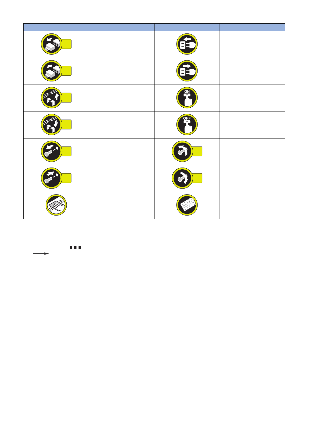
Explanation of Symbols
The following symbols are used throughout this Service Manual.
Symbols Explanation Symbols Explanation
Check.
Remove the claw.
Check visually.
Check a sound. Push the part.
Insert the claw.
1x
1x
1x
1x
1x
1x
1x
1x
Introduction
Symbols Explanation Symbols Explanation
Disconnect the connector. Connect the power cable.
Connect the connector. Disconnect the power cable.
Remove the cable/wire from the
cable guide or wire saddle.
Install the cable/wire to the cable
guide or wire saddle.
Remove the screw.
Install the screw.
Cleaning is needed. Measurement is needed.
The following rules apply throughout this Service Manual:
1. Each chapter contains sections explaining the purpose of specific functions and the relationship between electrical and
mechanical systems with reference to the timing of operation.
In the diagrams, represents the path of mechanical drive; where a signal name accompanies the symbol, the arrow
indicates the direction of the electric signal.
The expression "turn on the power" means flipping on the power switch, closing the front door, and closing the delivery unit
door, which results in supplying the machine with power.
2. In the digital circuits, '1' is used to indicate that the voltage level of a given signal is "High", while '0' is used to indicate "Low".
(The voltage value, however, differs from circuit to circuit.) In addition, the asterisk (*) as in "DRMD*" indicates that the DRMD
signal goes on when '0'.
In practically all cases, the internal mechanisms of a microprocessor cannot be checked in the field. Therefore, the operations
of the microprocessors used in the machines are not discussed: they are explained in terms of from sensors to the input of
the DC controller PCB and from the output of the DC controller PCB to the loads.
The descriptions in this Service Manual are subject to change without notice for product improvement or other purposes, and
major changes will be communicated in the form of Service Information bulletins.
All service persons are expected to have a good understanding of the contents of this Service Manual and all relevant Service
Information bulletins and be able to identify and isolate faults in the machine.
Turn on the power.
Turn off the power.
Loosen the screw.
Tighten the screw.

Contents
Contents
Safety Precautions...............................................................................................1
Points to Note about Turning Off the Main Power Switch................................................................... 2
Notes Before Servicing........................................................................................................................2
Notes On Assembly/Disassembly....................................................................................................... 2
Points to Note at Cleaning...................................................................................................................3
1. Product Overview.............................................................................................4
Features.............................................................................................................................................. 5
Features...............................................................................................................................................5
Specifications...................................................................................................................................... 6
Specifications....................................................................................................................................... 6
Names of Parts....................................................................................................................................7
External View........................................................................................................................................7
Cross Section....................................................................................................................................... 9
Option Construction...........................................................................................................................10
2. Technology..................................................................................................... 11
Basic Configuration........................................................................................................................... 12
Functional Construction....................................................................................................................... 12
Overview of the Electrical Circuitry....................................................................................................... 12
Component Configuration.................................................................................................................... 13
Controls.............................................................................................................................................15
Overview............................................................................................................................................ 15
Pickup/Feed Control............................................................................................................................15
Paper Presence/Absence Detection Control..........................................................................................16
Paper Surface Detection Control.......................................................................................................... 16
Lifter Control.......................................................................................................................................17
Remaining Paper Level Detection Control.............................................................................................17
Switching the Paper Size.....................................................................................................................18
Compartment Open/Close Control........................................................................................................19
Air Assist Control................................................................................................................................ 20
Cassette Heater Control (Option) ........................................................................................................ 22
Power Supply..................................................................................................................................... 23
Fan.................................................................................................................................................... 24
Jam Detection ....................................................................................................................................24
Upgrading..........................................................................................................................................26
Upgrading...........................................................................................................................................26
3. Periodical Service.......................................................................................... 27
List of Work for Scheduled Servicing................................................................................................ 28
4. Disassembly/Assembly................................................................................. 29
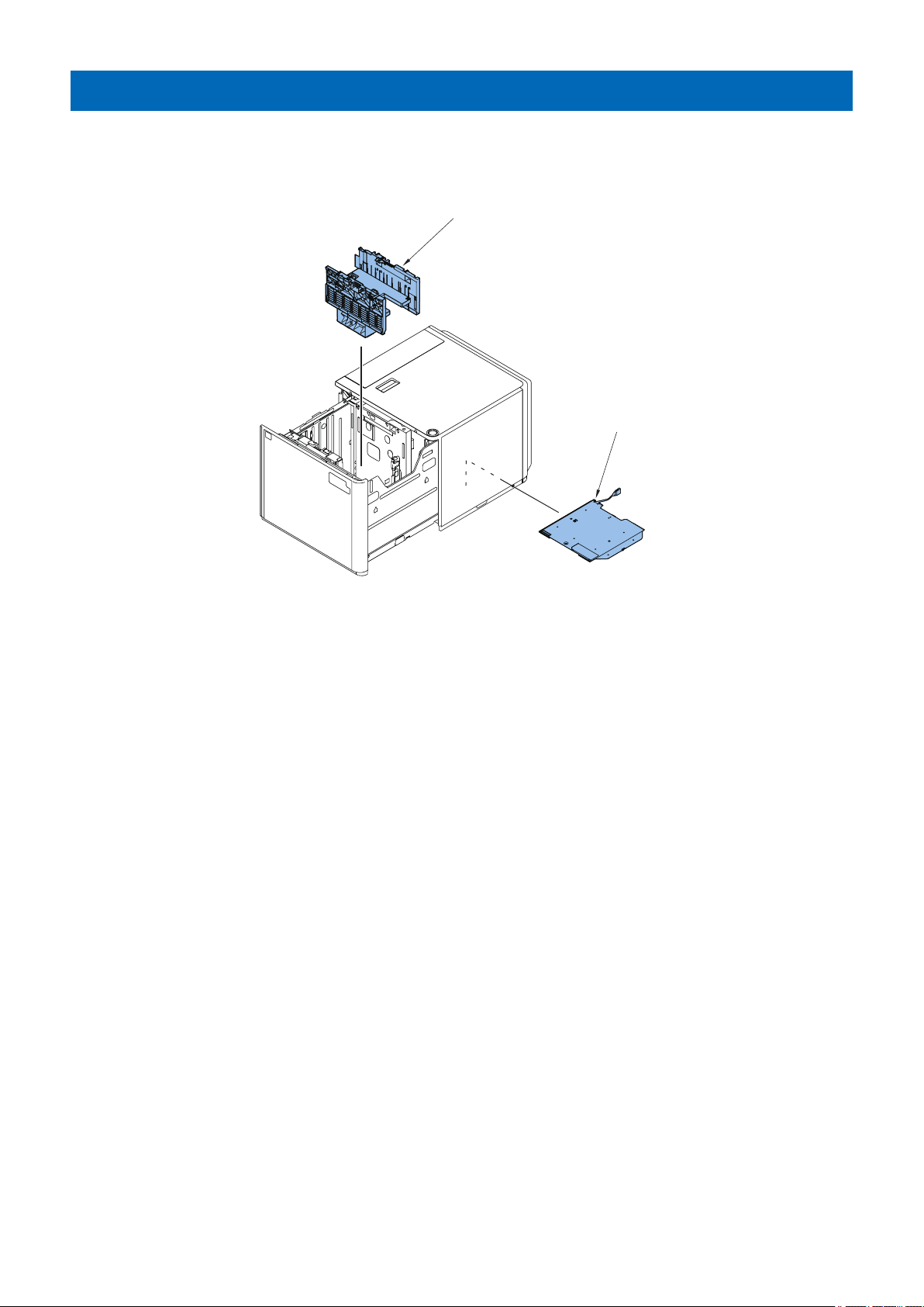
Removing from the Host Machine.....................................................................................................30
i

Contents
Removing from the Host Machine.........................................................................................................30
List of Parts....................................................................................................................................... 32
External Covers.................................................................................................................................. 32
Consumable Parts and Cleaning Points................................................................................................33
Main Units.......................................................................................................................................... 34
Sensors..............................................................................................................................................35
Solenoids........................................................................................................................................... 36
Motors................................................................................................................................................37
Fans...................................................................................................................................................38
PCBs..................................................................................................................................................39
Switches.............................................................................................................................................40
Others................................................................................................................................................ 41
External Covers.................................................................................................................................42
Removing the Left Upper Cover........................................................................................................... 42
Removing the Front Cover...................................................................................................................42
Removing the Right Cover...................................................................................................................43
Removing the Rear Cover....................................................................................................................44
Removing the Upper Cover .................................................................................................................45
Consumable Parts and Cleaning Points............................................................................................47
Removing the Deck Pickup Roller........................................................................................................ 47
Removing the Deck Feed Roller...........................................................................................................49
Removing the Deck Separation Roller.................................................................................................. 51
Main Units......................................................................................................................................... 54
Removing the Pickup Assembly........................................................................................................... 54
Opening the Compartment...................................................................................................................56
Removing the Compartment................................................................................................................ 56
Heaters..............................................................................................................................................60
Removing the Cassette Heater............................................................................................................ 60
Removing the Air Heater .....................................................................................................................61
Solenoids...........................................................................................................................................64
Removing the Compartment Open Solenoid......................................................................................... 64
Removing the Deck Pickup Release Solenoid ...................................................................................... 65
Motors............................................................................................................................................... 67
Removing the Deck Lifter Motor........................................................................................................... 67
Fans.................................................................................................................................................. 69
Removing the Pickup Release Solenoid Cooling Fan ............................................................................69
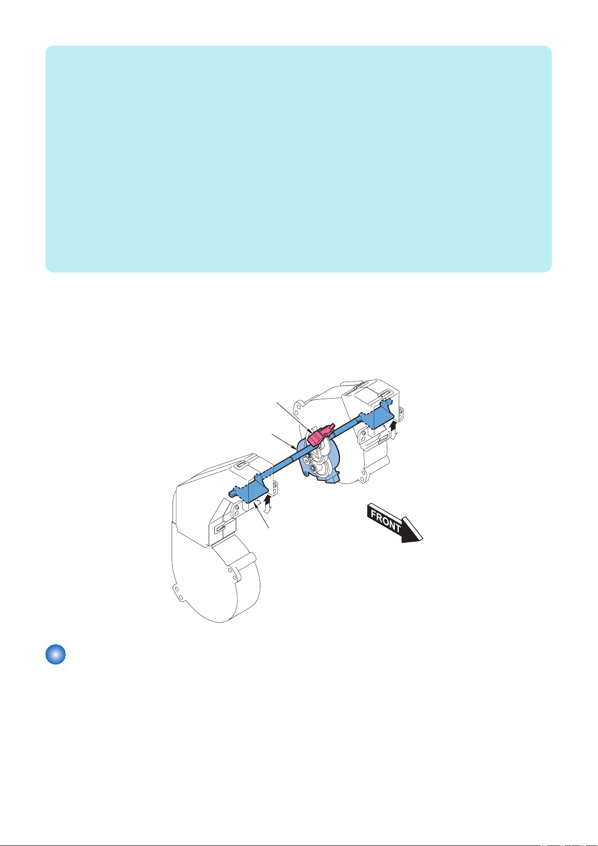
Lifter Wire .........................................................................................................................................71
Removing the Lifter Wire..................................................................................................................... 71
Installation of the Lifter Wire.................................................................................................................74
PCBs................................................................................................................................................. 84
Removing the Deck Driver PCB........................................................................................................... 84
Removing the Paper Width Detection PCB........................................................................................... 84
5. Adjustment..................................................................................................... 87
Adjustment ....................................................................................................................................... 88
Overview............................................................................................................................................ 88
Actions when Replacing the Parts.....................................................................................................90
Front Cover........................................................................................................................................ 90
Pickup Assembly.................................................................................................................................90
ii

Contents
Compartment......................................................................................................................................93
Deck Driver PCB ................................................................................................................................94
Paper Width Detection PCB.................................................................................................................94
Other Adjustment ............................................................................................................................. 96
Adjusting the Pressure of the Deck Separation Roller............................................................................ 96
Adjusting the Paper Separation ...........................................................................................................96
6. Installation.................................................................................................... 100
How to Utilize this Installation Procedure........................................................................................101
Description on the Parts Included in the Package................................................................................ 101
Symbols in the Illustration.................................................................................................................. 101
Checking before Installation............................................................................................................102
Checking the Installation Space..........................................................................................................102
Points to Note on Installation..............................................................................................................102
Checking the Power Supply............................................................................................................... 103
Check Items When Turning OFF the Main Power................................................................................ 103
Product Name...................................................................................................................................103
Unpacking Procedure......................................................................................................................104
Unpacking Procedure........................................................................................................................ 104
Checking the Contents....................................................................................................................105
imageRUNNER ADVANCE 8500 Series............................................................................................. 105
imagePRESS C10000VP / C8000VP Series....................................................................................... 107
Installation Procedure......................................................................................................................109
imageRUNNER ADVANCE 8500 Series............................................................................................. 109
imagePRESS C10000VP / C8000VP Series....................................................................................... 119
Checking after Installation...............................................................................................................132
imageRUNNER ADVANCE 8500 Series............................................................................................. 132
imagePRESS C10000VP / C8000VP Series....................................................................................... 132
Paper Positioning Check / Adjustment Procedure.......................................................................... 133
imageRUNNER ADVANCE 8500 Series............................................................................................. 133
imagePRESS C10000VP / C8000VP Series....................................................................................... 136
Cassette Heater Assembly..............................................................................................................139
Check Items when Turning OFF the Main Power.................................................................................139
Checking the Supplied Parts.............................................................................................................. 139
Removing from the Host Machine.......................................................................................................139
Installation Procedure........................................................................................................................140
APPENDICES....................................................................................................144
Service Tools...................................................................................................................................145
Solvents and Oils.............................................................................................................................. 145
Special Tools.................................................................................................................................... 145
General Circuit Diagram..................................................................................................................146
General Circuit Diagram (1/3 )............................................................................................................146
General Circuit Diagram (2/3).............................................................................................................147
General Circuit Diagram (3/3).............................................................................................................148
iii

Safety Precautions
Points to Note about Turning Off the
Main Power Switch............................2
Notes Before Servicing......................... 2
Notes On Assembly/Disassembly.........2
Points to Note at Cleaning.................... 3
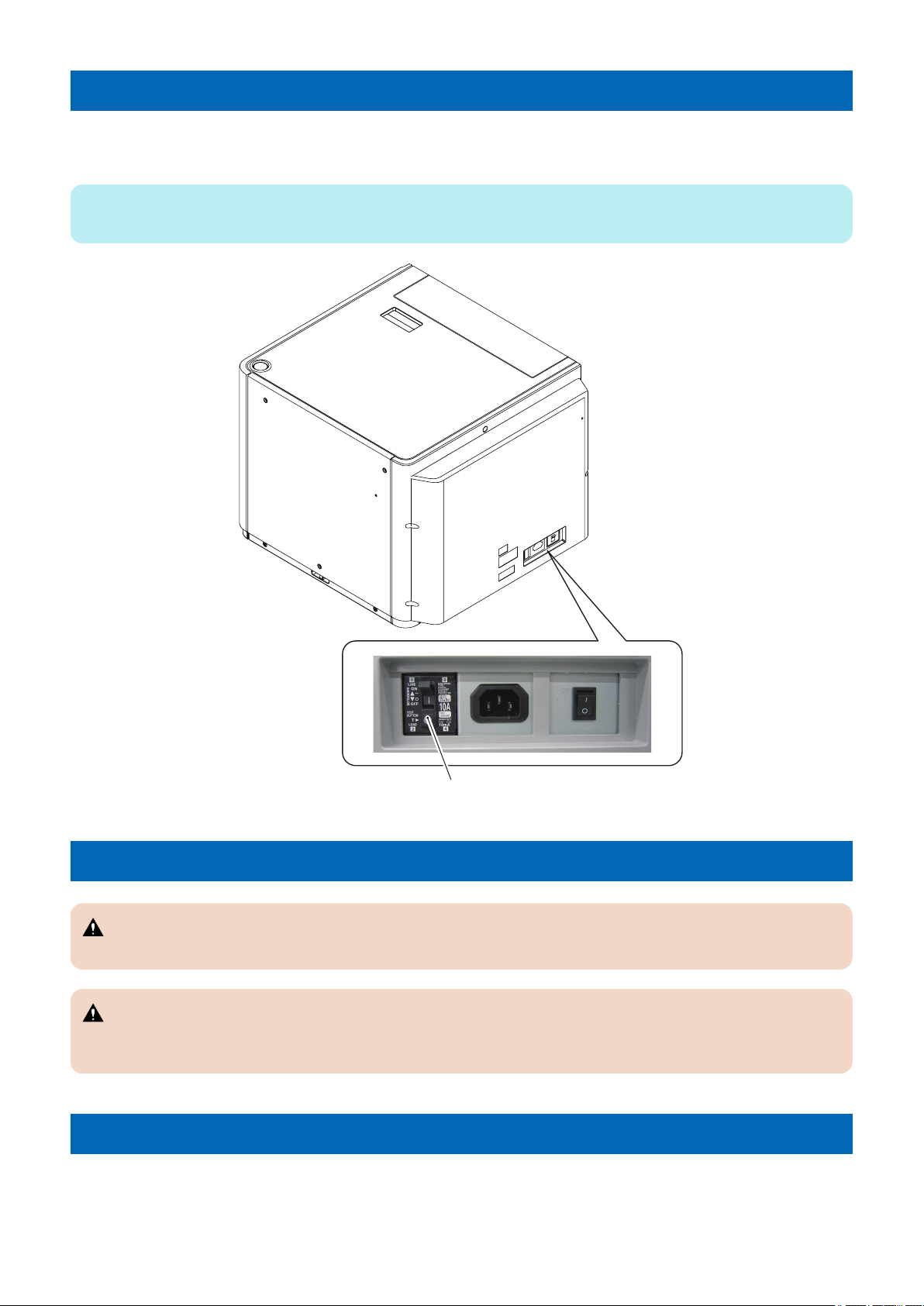
Leakage Breaker
Safety Precautions
Points to Note about Turning Off the Main Power Switch
This equipment does not have a main power switch, but it has only a leakage breaker. This equipment is powered when the main
power switch of the host machine is turned on. The leakage breaker detects overcurrent and power leakage.
NOTE:
Explain to the customer that the leakage breaker must be checked once or twice a month and the result must be recorded.
Notes Before Servicing
CAUTION:
At servicing, be sure to turn off the power source according to the specified steps and disconnect the power plug.
CAUTION:
Do not turn off the power switch when downloading is under way. Turning off the main power switch while downloading is
under way can disable the machine.
Notes On Assembly/Disassembly
Follow the items below to assemble/disassemble the device.
1. Disconnect the power plug to avoid any potential dangers during assembling/disassembling works.
2. If not specially instructed, reverse the order of disassembly to reinstall.
2

Safety Precautions
3. Ensure to use the right screw type (length, diameter, etc.) at the right position when assembling.
4. To keep electric conduction, binding screws with washers are used to attach the grounding wire and the varistor. Ensure to
use the right screw type when assembling.
5. Unless it is specially needed, do not operate the device with some parts removed.
6. Never remove the paint-locked screws when disassembling.
Points to Note at Cleaning
CAUTION:
When performing cleaning using organic solvent such as alcohol, be sure to check that the component of solvent is
vaporized completely before assembling.
3

1
Product Overview
Features................................................5
Specifications........................................6
Names of Parts..................................... 7
Option Construction............................ 10

1. Product Overview
Features
Features
• The various paper sizes from the A5 to 13"X19"(330.0X482.6mm) are supported. In addition, the custom paper size is
supported, too.
• The high stacking of maximum 3,500 sheets (80 g/m2) is possible.
• The user can change the stacking paper size easily by the side and rear guide plates with the free stop mechanism and the
automatic paper size detection function.
• The envelope can be picked up by attaching the optional Envelope Feeder Attachment.
• The replacement work of the consumable parts is easy.
5

Specifications
Specifications
Item Specifications Remarks
Pickup method Retard separation + Air assist (switches between warm and cool cur-
rents to suit paper type/environment)
Paper accommodation
Paper type Thin paper (52 to 79 g/m2), Plain paper (80 to 105 g/ m2), Heavy paper
Paper size 13 X 19 (330.2 X 482.6 mm), SRA3 (320 X 450 mm), 12 X 18 (304.8
Paper weight 52 g/m2 to 300 g/m2
Stacking height 385 mm (height to bottom of arrow on stack limit label) Envelope: 100
Stacking capacity Approx. 3500 sheets (equivalent of 80 g/m2)
Size switching Switching the guide plates by the user operation
Paper size detection
Remaining paper
level detection
Operation switch Compartment open button
Display None
Ecological consideration
Dimensions (W) 717 X (D) 686 X (H) 568 mm
Weight Approx. 76 kg
Power supply AC 100 to 240 V 50/60 Hz 2.4A
Operating noise Host machine noise + 2.5 dB
Front loading
(106 to 300 g/m2), Color paper, Recycled paper, Pre-punched paper,
Transparency, Label paper, Tab paper, Bond paper, Letterhead, Coated paper, Textured paper, Vellum paper, Envelopes*1
X 457.2 mm), A3, A4, A4R, A5R, B4, B5, B5R, 11 X17 (279 X 432 mm),
LGL, LTR, LTRR, EXEC, STMTR, 8K, 16K, 16KR, Envelopes (Monarch, COM10, ISO-C5, DL, Kakugata 2, Nagagata 3, Yougatanaga 3,
10 X 13 (254 X 330.2 mm)*2, 9 X 12 (228.6 X 304.8 mm), 6 X 9 (152.4
X 228.6 mm))*1, Custom size (100 X 148 mm to 330.2 X 487.7 mm)
mm*1
Yes (Paper width: detected by the volume sensor, Paper length: detected by the photo-interrupter)*1
Yes
Environment sensor, Air heater (standard), Cassette heater (option,
supplied as the service parts)
Center reference
Different depending on the host machine.
*1: Only when the optional Envelope Feeder Attachment is installed.
Different depending on the host machine.
*1: Only when the optional Envelope Feeder Attachment is installed.
*2: Do not use the Envelope Feeder Attachment.
*1: When the paper is Yougatanaga 3, the
stack height is 160 mm or less.
*1: The size of envelope and custom size
paper are not detected.
1. Product Overview
6
Names of Parts
[5]
[4]
[1]
[2]
[3]
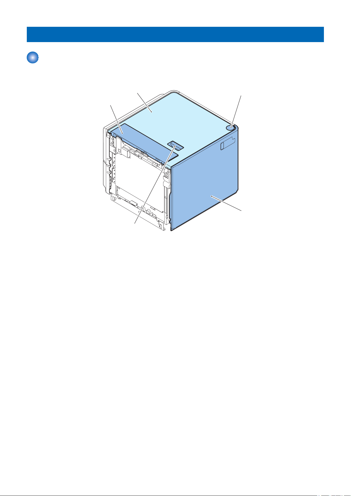
External View
■ Front
1. Product Overview
[1] Left upper cover
[2] Upper cover
[3] Compartment open button
[4] Front cover
[5] Deck release lever
7
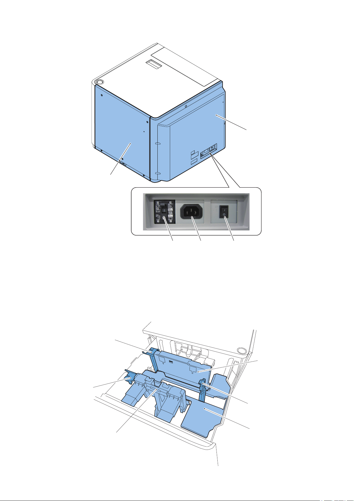
■ Rear
[2]
[1]
[3][4][5]
[4]
[2]
[5]
[1]
[6]
[3]
1. Product Overview
[1] Rear cover
[2] Right cover
[3] Cassette heater switch
[4] Power socket
[5] Leakage breaker
■ Internal
8
[1] Side guide plate (rear)
[2]
[4]
[3]
[1]
[5] [6]
[2] Rear guide plate
[3] Lifter
[4] Side guide plate (front)
[5] Envelope side guide plate (front)
[6] Envelope side guide plate (rear)
Cross Section
1. Product Overview
[1] Deck pull-out roller
[2] Deck separation roller
[3] Deck feed roller
[4] Deck pickup roller
[5] Blow-out vent (warm air)
[6] Blow-out vent (cool air)
9
Option Construction
Cassette Heater
Envelope Feeder Attachment-G1
The following optional equipment can install to the this equipment.
• Envelope Feeder Attachment-G1 : User installation
• Cassette heater : Supplied as the service parts
1. Product Overview
10

2
Technology
Basic Configuration.............................12
Controls...............................................15
Upgrading............................................26
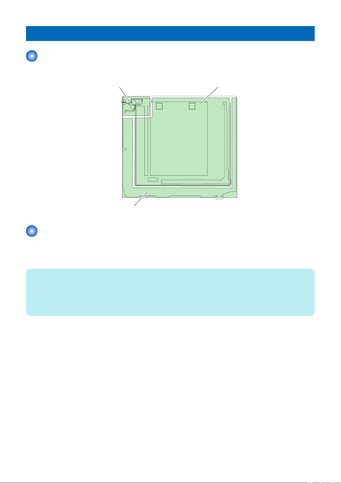
1.Pickup/feed system 2.Compartment system
3.Deck control system
2. Technology
Basic Configuration
Functional Construction
The POD Deck Lite is grouped into the following 3 blocks: Pickup/feed system, Compartment system, Deck control system.
Overview of the Electrical Circuitry
The operating sequence for the Paper Deck Unit is controlled by the DC controller PCB in the host machine. The DC controller
PCB is equipped with CPU. The electric control for the Paper Deck Unit is controlled by the deck driver PCB. The deck driver
PCB is equipped with EEPROM.
NOTE:
The EEPROM stores the following adjustment value.
• ID for model discrimination
• Small size AD value/large size AD value (volume value of the free size detection PCB)
• Remaining paper level adjustment value (up/down movement distance of the lifter)
• Wind-power correction value of the warming/cooling fan
12
Host
machine
Deck driver
PCB(PCB1)
Box driver
PCB(PCB2)
Sensor
Motor
Switch
Motor
Sensor
Sensor
Switch
Fan
Solenoid
Fan
ASIC
Motor driver
DC/DC converter
Regulator
EEPROM
Swing driver
PCB(PCB6)
Motor driver
[2]
[4]
[3]
[1]
2. Technology
Component Configuration
■ Roller Layout
[1] Deck pull-out roller
[2] Deck separation roller
[3] Deck feed roller
[4] Deck pickup roller
13
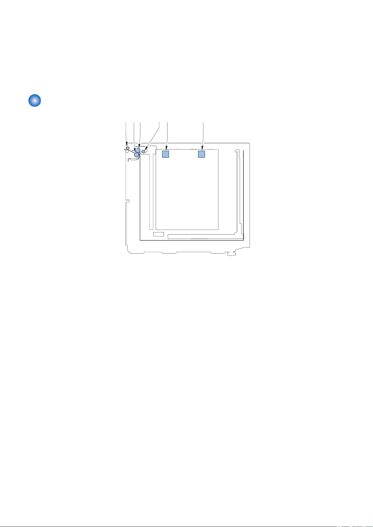
■ Sensor Layout
SR6
SR7
M2
SL2
M1
M4
M3
SL1
Only the optical sensors on the feed path are shown below.
SR6 Deck pull-out sensor
SR7 Deck pickup sensor
2. Technology
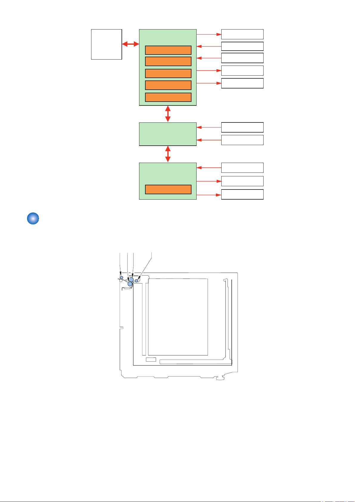
■ Drive Configuration
M1 Deck pickup motor
M2 Deck pull-out motor
M3 Deck lifter motor
M4 Swing motor
SL1 Compartment open solenoid
SL2 Deck pickup release solenoid
14
M2
SL2
M1
Deck pull-out
roller
Deck separation roller
SR6
Deck feed roller
Deck pickup roller
2. Technology
Controls
Overview
Item Reference
1. Pickup/Feed System Pickup/feed control “Pickup/Feed Control” on page 15
Paper presence/absence detection control “Paper Presence/Absence Detection Control” on page
16
Paper surface detection control “Paper Surface Detection Control” on page 16
2. Compartment system Lifter control “Lifter Control” on page 17
Remaining paper level detection control “Remaining Paper Level Detection Control” on page 17
Switching the paper size “Switching the Paper Size” on page 18
Compartment open/close control “Compartment Open/Close Control” on page 19
Air assist control “Air Assist Control” on page 20
Swing operation “Swing Operation” on page 22
3. Deck control system Cassette heater control (option) “Cassette Heater Control (Option) ” on page 22
Power supply “Power Supply” on page 23
4. Others Fan control “Fan” on page 24
Jam detection “Jam Detection ” on page 24
Pickup/Feed Control
The paper deposited in the compartment is held up by the work of the lifter, and is kept to a specific level.When the start key on
the host machine is pressed, and the drive of the deck pickup motor (M1) starts to rotate the pickup roller to pick up paper. At
this time, the deck feed roller and the deck separation roller operate to make sure that only a single sheet of paper is picked up
and moved. When the deck pull-out sensor (SR6) detects paper at the time of heavy paper (151 g/m2 or more) and transparency
setting, the deck pickup release solenoid (SL2) goes on to move the deck pickup roller away from the stack of paper. The deck
pull-out roller starts to rotate when the deck pull-out motor (M2) goes on. After pickup, the paper is moved as far as the registration
roller of the host machine.
NOTE:
Service Mode
• Setting of Deck Pickup Roller eng/diseng
To set whether to disengage the Pickup Roller of the POD Deck Lite every time paper is picked up.
Lv2) COPIER > OPTION > FEED-SW > DK1-PSP
< Setting value >
0 to 1
• 0: Disengaged only for heavy paper (151 g/m2 or more) and transparency
• 1: Disengaged regardless of paper type
< Use case >
• When Pickup Roller trace occurs on the 2nd sheets and later
< Caution >
• If the machine is continued to be used while the setting value is 1, the life of the solenoid becomes shorter.
15

Deck paper
sensor(SR15)
<Paper presence>
Paper detecting lever
Paper
<Paper absence>
Lifter
Lifter
Paper level sensor (SR3)
Detection flag
Paper
Lifter
2. Technology
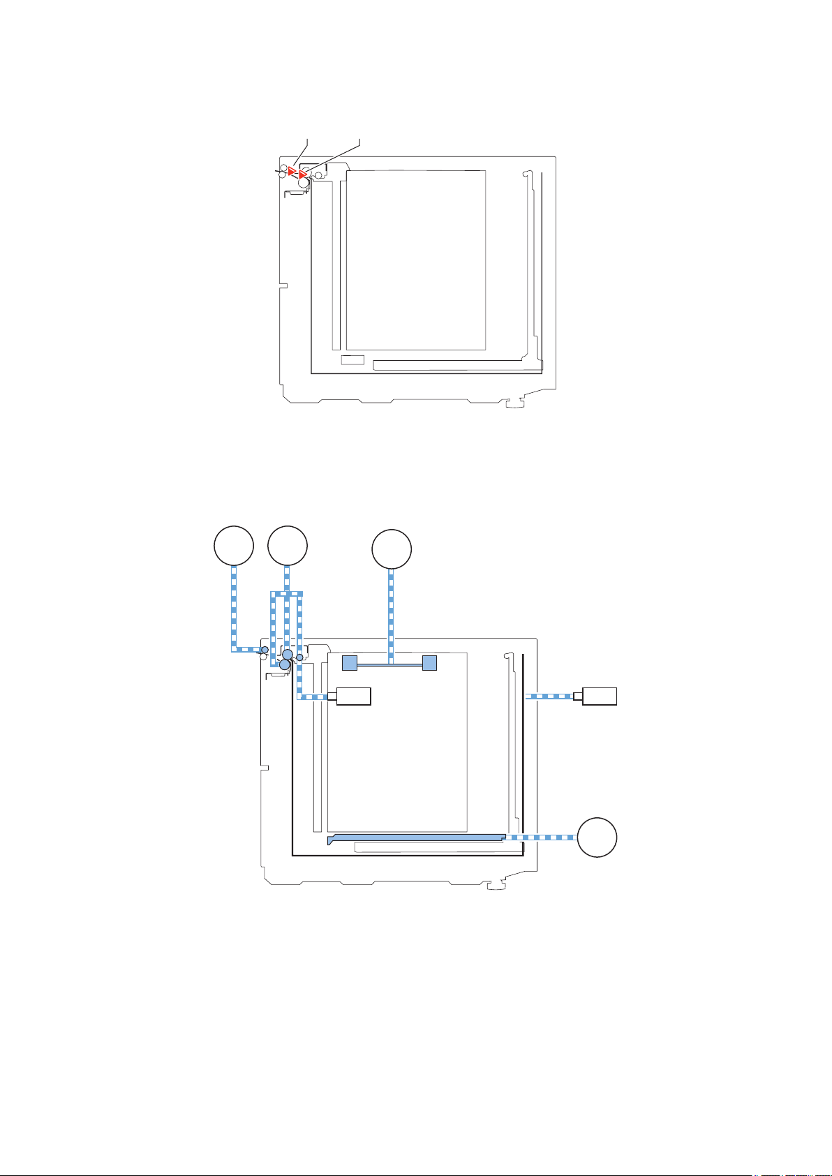
Paper Presence/Absence Detection Control
The presence/absence of paper inside the compartment is checked by the deck paper sensor (SR15) of the pickup assembly.
When the paper runs out and the paper detecting lever of the pickup assembly passed the deck paper sensor (SR15) as a result,
the host machine indicates the absence of paper on its control panel.
Paper Surface Detection Control
The paper level sensor (SR3) mounted at the pickup assembly is used to detect the paper surface. When the detection flag of
the pickup roller holder is pushed up by the top surface of paper with the upward movement of the lifter, the paper level sensor
(SR3) detects it and the lifter stops to keep the top surface of paper at the pickup position.
NOTE:
Service Mode
• Adjustment of paper surface height: Deck
Lv2) COPIER > ADJUST > FEED-ADJ > DK1-PKLV
To adjust the pickup position of the POD Deck Lite
+: Move up ( When a pickup failure occurs )
-: Move down ( When double feed occurs)
< Setting value >
-10 to -1: Move down by 1 mm, 0: 0 mm, 1: Move up by 1 mm, 2 to 10: Move up by 2 mm
< Use case >
When a pickup failure occurs, When double feed occurs
< Caution >
If the value is too large, double feed may occur. If the value is too small, a pickup failure may occur.
• Set paper surface level down: Deck standby
Lv2) COPIER > OPTION > FEED-SW > DK1-LDWN
To set whether to lower the paper surface level in the POD Deck Lite below pickup position during standby. When a trace which
looks like that the Pickup Roller had contact with a paper occurs, set 1. It returns to pickup position at the time of starting a job.
< Setting value >
0 to 1
0: Normal (Pickup Roller is in contact), 1: Paper surface level moves down
< Use case >
When Pickup Roller trace occurs on transparency paper.
< Caution >
When 1 is set, FCOT becomes longer.
16

SR13
SW4
SR9
SR2
SR3
SR4
SR5
SR8
M3
2. Technology
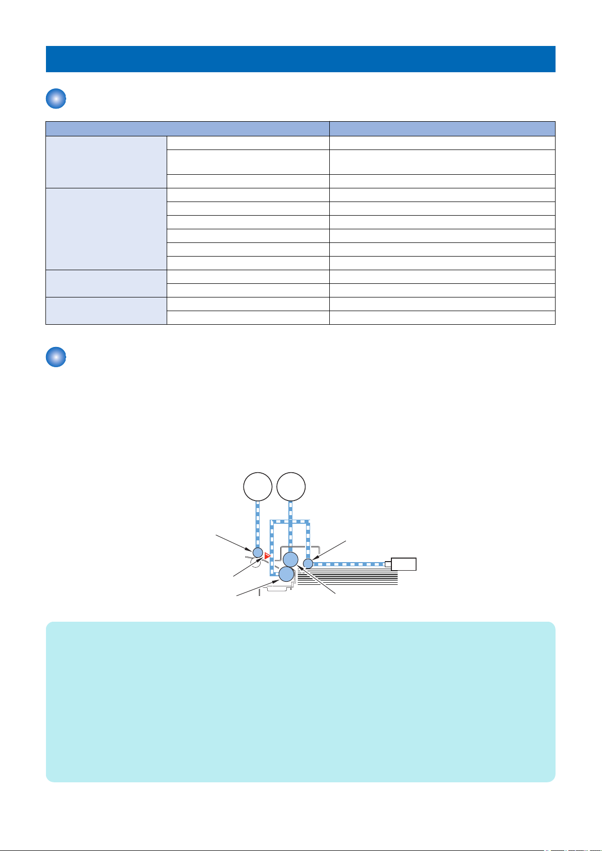
Lifter Control
■ Moving Up the Lifter
The lifter starts to move up when the compartment open/close switch (SW4) and the compartment open/close sensor (SR9)
detect that the compartment has been set in place.The lifter then stops when the paper level sensor (SR3) detects the top surface
of the stack of paper placed on the lifter.The deck lifter upper limit sensor 1/2 (SR4/5) is used to prevent damage otherwise caused
by the failure of the lifter to stop after the sensor lever blocks the paper level sensor (SR3).The machine is also equipped with a
protective mechanism by means of an obstacle sensor (SR8) used to prevent damage to the lifter cable and resin gears lest a
foreign object inside the compartment should hit the ceiling before the paper level sensor (SR3) detects the top surface of the
stack of paper.
■ Moving Down the Lifter
The lifter starts to move down when the compartment open switch is pushed until the lifter passes through the sensor lever of
the relay paper sensor (SR2). When paper is supplied in this condition, the lifter moves down to the position where the paper
passes through the sensor lever as the paper pushes the sensor lever. The lifter keeps moving down until the lifter passes through
the deck lifter lower position sensor (SR13) which detects maximum paper supply position each time when paper is supplied.
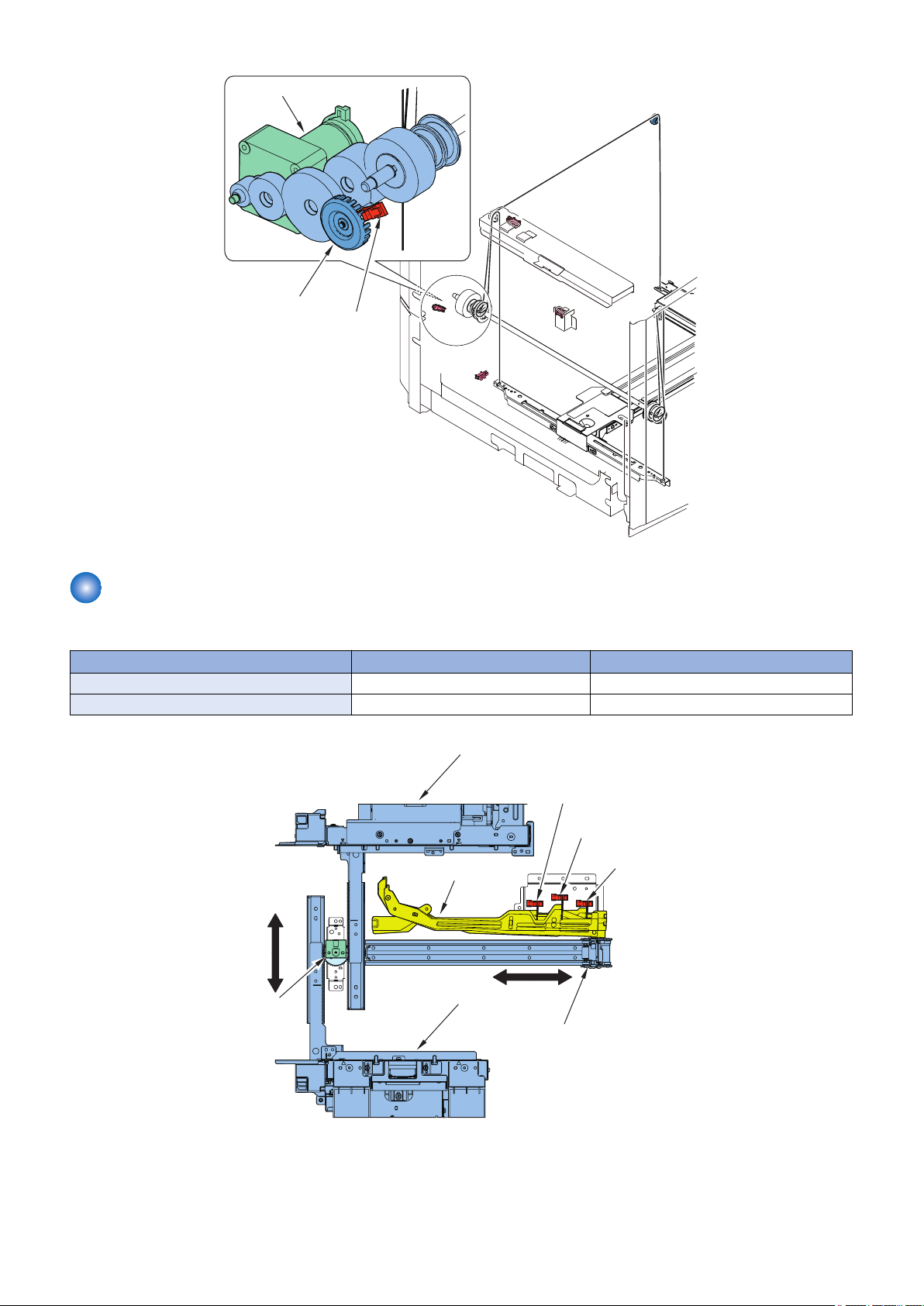
Remaining Paper Level Detection Control
The level of the paper remaining is detected by counting the pulses of the encoder for the lifter motor rotation sensor (SR14) that
represent the distance of movement of paper from the deck lifter lower position sensor (SR13) to the paper level sensor (SR3).The
encoder for the lifter motor rotation sensor (SR14) rotates in synchronization with the deck lifter motor (M3).When the relay paper
sensor (SR2) became OFF from ON during paper feed, the count value of the pulse is reset for the correction of the detection
error by the wire growth.The lifter position information is memorized in the EEPROM of the deck driver PCB. Therefore the lifter
position control is not performed after sleep again.The level of the paper remaining is indicated on the display on the host machine.
17
SR2
SR3
SR13
SR14
Encoder
Deck lifter motor (M3))
Lifter motor rotation
sensor(SR14)
Side guide plate (rear)
Side guide plate (front)
Rear guide plate
Paper width
detection PCB
(PCB7)
Paper size sensor 1(SR10)
Sensor flag
Paper size
sensor 2(SR11)
Paper size
sensor 3(SR12)
2. Technology
Switching the Paper Size
Paper size can be automatically detected by adjusting the position of the guide plate.
Paper size sensor 1/2/3 (SR10/11/12) Size for feed direction ON / OFF combination of sensors
Paper width detection PCB (PCB7) Size for width direction Volume
Sensor name Description Detection method
18

NOTE:
Service mode
• Adjsutment of POD Deck Lite A4 paper width
(Lv1) COPIER> ADJUST> CST-ADJ> PDK-A4
< Use case >
• When replacing the DC Controller PCB/clearing RAM data.
• When replacing the Paper Width Sensor PCB or registering a new value.
< Caution >
After the setting value is changed, write the changed value in the service label.
• Registration of POD Deck Lite A4 standard width
(Lv1) COPIER> FUNCTION> CST> PDK-A4
< Use case >
• When replacing the DC Controller PCB/clearing RAM data.
• When replacing the Paper Width Sensor PCB or registering a new value.
< Caution >
After execution, check the registered value by COPIER> ADJUST> CST-ADJ> PDK-A4, and write it down on the service
label.
• Adjsutment of POD Deck Lite A5R paper width
(Lv1) COPIER> ADJUST> CST-ADJ> PDK-A5R
< Use case >
• When replacing the DC Controller PCB/clearing RAM data.
• When replacing the Paper Width Sensor PCB or registering a new value.
< Caution >
After the setting value is changed, write the changed value in the service label.
2. Technology
• Registration of POD Deck Lite A5R standard width
(Lv1) COPIER> FUNCTION> CST> PDK-A5R
< Use case >
• When replacing the DC Controller PCB/clearing RAM data.
• When replacing the Paper Width Sensor PCB or registering a new value.
< Caution >
After execution, check the registered value by COPIER> ADJUST> CST-ADJ> PDK-A5R, and write it down on the service
label.
Compartment Open/Close Control
When the compartment open switch is pushed, the deck lifter motor (M3) starts to rotate to cause the lifter to move down. When
1 sec passes thereafter, the compartment open solenoid (SL1) goes on to release the lock of the compartment. When the lock
is released, the force of the spring causes the compartment to move forward by several centimeters.When the relay paper sensor
(SR2) or the deck lifter lower position sensor (SR13) goes on in response, the lifter stops to move down.The lock of the
compartment is released a moment later to prevent the paper from becoming trapped by a guide or the like, possibly occurring
if the compartment was let to open before the paper has dropped.When the compartment open/close switch (SW4) and the
compartment open/close sensor (SR9) go on by pushing the compartment with hands to set it in the equipment to close the
compartment, the lifter moves up to the pickup position.The compartment open indicator (LED100) on the open switch PCB
flashes while the compartment is being opened/closed, and remains on as long as the compartment remains open.
19

SW5
Spring
Compartment open/close arm
Compartment open solenoid(SL1)
Compartment open/close sensor(SR9)
Compartment open/close
detection switch(SW4)
Fan safety switch(SW5)
2. Technology
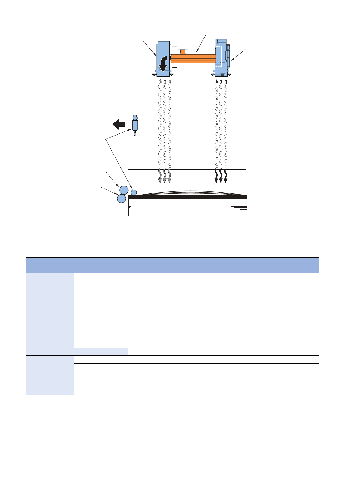
Air Assist Control
■ Overview
To facilitate separation of paper, the machine executes air assist control.
The fans (FM2, FM3) are combined to blow air against the paper so that the paper is shifted slightly to lose attraction, ultimately
preventing double-feeding.
To facilitate separation of paper in the high humidity environment, an air heater unit (H2) is equipped as standard.
A warming fan (FM2) with an air heater blows hot wind against paper to reduce the humidity, thus facilitating separation of paper.
20
Cool airWarm air
Pickup direction
Paper
Pickup roller
Feed roller
Separation rolle
Warming fan(FM2)
Air heater(H2)
Cooling fan(FM3)
2. Technology
■ Air Assist Control
The air assist control mechanism is turned on by the DC controller PCB of the host machine and by way of the deck driver PCB.
The air assist mechanism consists of the following control items:
Paper type*3 Warming fan
(FM2)
Non coated paper Thin paper (52 to 79 g/
m2), Plain paper (80 to
105 g/m2), Heavy paper (106 to 150 g/ m2),
Pre-punched paper,
Coated paper ON*1 ON*1 ON*2 ON
Special paper Transparency ON ON OFF ON
Bond paper, Vellum paper
Heavy paper (151 to
300 g/m2), Letterhead,
Textured paper
Recycled paper ON ON OFF ON
Textured paper ON ON OFF ON
Label paper ON ON OFF ON
Postcard OFF OFF OFF ON
Envelope OFF OFF OFF OFF
OFF OFF OFF OFF
ON*1 ON*1 OFF ON
*1: Switches the wind-power of fan according to the detected temperature and humidity of the environment sensor (SR18).
*2: Switches the ON/OFF and wind-power of fan according to the detected temperature and humidity of the environment sensor
(SR18).
*3: Different depending on the host machine.
Cooling fan (FM3) Air heater (H2) Swing motor (M4)
21
Swing motor(M4)
Swing HP sensor(SR16)
Shutter
2. Technology
NOTE:
Service Mode
• ON/OFF of POD Deck Lite air assist
(Lv.2) COPIER > OPTION > FEED-SW > DK1-AIR
• Deck Air Float Fan airflow amnt: dwstm
(Lv.2) COPIER > OPTION > FEED-SW > DK1-ALVD
• Deck Air Float Fan airflow amnt: upstream
(Lv.2) COPIER > OPTION > FEED-SW > DK1-ALVU
To adjust the airflow amount of the Air Floatation Fan of the POD Deck Lite.
When making an adjustment, be sure to adjust the setting of DK1-ALVD and DK1- ALVU at the same time.
<Setting value >
-10 to 10 [default: 0]
<Use case >
When double-feed occurs
<Caution >
If the value is large, uneven transfer may occur. If the value is small, double feed may occur.
■ Swing Operation
This equipment combines the air blowing operation against paper with the swing operation of the shutter to improve separation
of paper. The swing motor (M4) drives the shutter to move up and down.
The direction of air blow against paper changes up or down repeatedly, vibrating the paper for easier separation.
The swing HP sensor (SR16) detects a failure of up and down operation of the shutter and the home position of the shutter.
Paper type: Different depending on the host machine.“Air Assist Control” on page 21
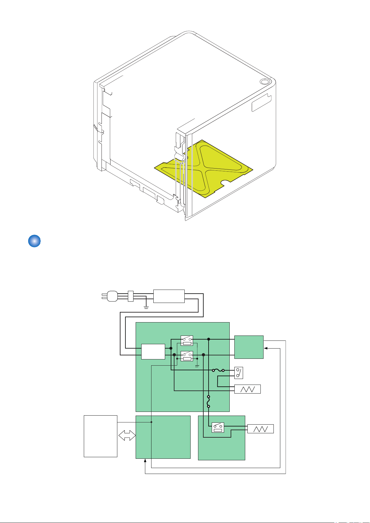
Cassette Heater Control (Option)
To facilitate separation of paper in a high humidity environment, a cassette heater unit is available optionally. When the cassette
heater (H1) is powered, the temperature in the deck becomes suitable and thereby the humidity lowers, facilitating separation of
paper. When the cassette heater switch mounted at the rear of this equipment is set at OFF, the cassette heater (H1) is not
powered. When the cassette heater switch is set to ON, the cassette heater is continuously powered.
22
H1
Deck driver
PCB (PCB1)
Air heater driver
PCB (PCB5)
Inlet
Leakage breaker
ELCB1
AC relay PCB (PCB4)
DC power
supply PCB
(UN1)
RL1
RL2
Cassette heater
switch(SW2)
Cassette heater(H1)
Air heater
(H2)
RL3
Remote signal
Host machine
24䠲
Noise
filter
2. Technology
Power Supply
The machine's AC power is supplied by an external power outlet, and it is sent through a leakage breaker (ELCB1) to reach the
AC relay PCB.The machine's DC power supply is sent to the individual loads from the DC power supply PCB through the deck
driver PCB (or directly).
23
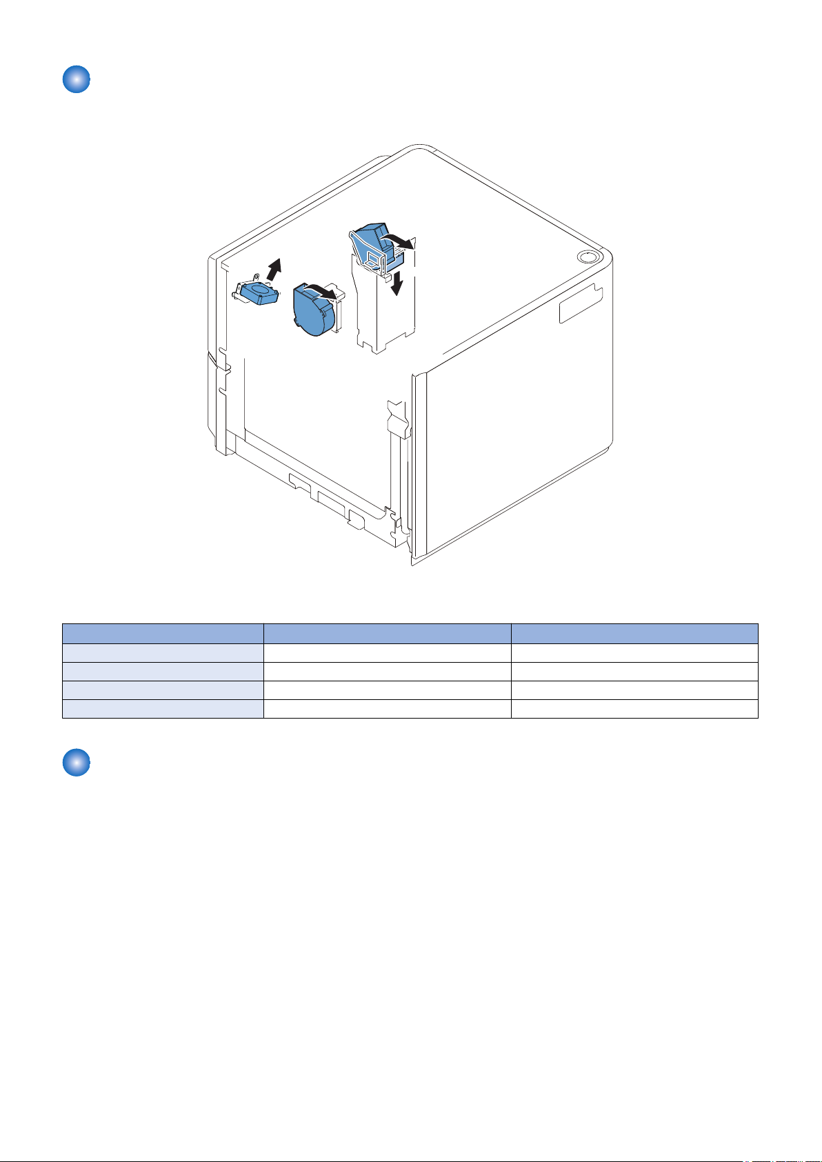
Fan
FM3
FM1
FM2
FM4
■ Location of Fans
2. Technology
■ Function of Fans
No. Name Function
FM1 Power supply cooling fan Cool the DC power supply PCB
FM2 Warming fan Improve separating performance of the paper
FM3 Cooling fan Improve separating performance of the paper
FM4 Pickup release solenoid cooling fan Cool the deck pickup release solenoid (SL2)
Jam Detection
The machine uses the following 2 sensors to make sure that paper moves smoothly inside it.The presence/absence of a jam is
checked using the signals coming from the host machine at such times as programmed in the host machine. When the host
machine detects a jam, the machine discharges all paper that has been picked up before the jam paper, and then stops the
operation. The host machine offers instructions on how to remove jams on its control panel display.
24
 Loading...