

Canon MF8100 Series, LaserBase MF8180C Service Manual

Jan 20 2006
Service Manual
MF8100 Series
LaserBase MF8180C


Application
This manual has been issued by Canon Inc. for qualified persons to learn technical theory, installation, maintenance, and repair
of products. This manual covers all localities where the products are sold. For this reason, there may be information in this
manual that does not apply to your locality.
Corrections
This manual may contain technical inaccuracies or typographical errors due to improvements or changes in products. When
changes occur in applicable products or in the contents of this manual, Canon will release technical information as the need
arises. In the event of major changes in the contents of this manual over a long or short period, Canon will issue a new edition
of this manual.
The following paragraph does not apply to any countries where such provisions are inconsistent with local law.
Trademarks
The product names and company names used in this manual are the registered trademarks of the individual companies.
Copyright
This manual is copyrighted with all rights reserved. Under the copyright laws, this manual may not be copied, reproduced or
translated into another language, in whole or in part, without the written consent of Canon Inc.
COPYRIGHT © 2001 CANON INC.
Printed in Japan
Caution
Use of this manual should be strictly supervised to avoid disclosure of confidential information.
Introduction
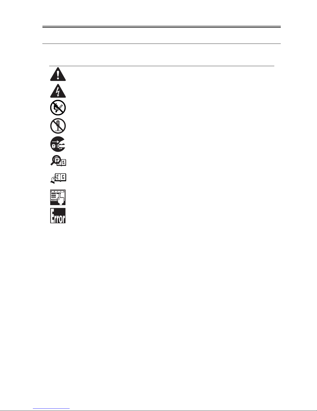
Symbols Used
This documentation uses the following symbols to indicate special information:
Symbol Description
Indicates an item of a non-specific nature, possibly classified as Note, Caution, or Warning.
Indicates an item requiring care to avoid electric shocks.
Indicates an item requiring care to avoid combustion (fire).
Indicates an item prohibiting disassembly to avoid electric shocks or problems.
Indicates an item requiring disconnection of the power plug from the electric outlet.
Indicates an item intended to provide notes assisting the understanding of the topic in question.
Indicates an item of reference assisting the understanding of the topic in question.
Provides a description of a service mode.
Provides a description of the nature of an error indication.
Memo
REF.

Introduction
The following rules apply throughout this Service Manual:
1. Each chapter contains sections explaining the purpose of specific functions and the relationship between electrical and mechanical systems with reference to the timing of operation.
In the diagrams, represents the path of mechanical drive; where a signal name accompanies the symbol , the arrow indicates the
direction of the electric signal.
The expression "turn on the power" means flipping on the power switch, closing the front door, and closing the delivery unit door, which results in
supplying the machine with power.
2. In the digital circuits, '1'is used to indicate that the voltage level of a given signal is "High", while '0' is used to indicate "Low".(The voltage value, however, differs from circuit to circuit.) In addition, the asterisk (*) as in "DRMD*" indicates that the DRMD signal goes on when '0'.
In practically all cases, the internal mechanisms of a microprocessor cannot be checked in the field. Therefore, the operations of the microprocessors
used in the machines are not discussed: they are explained in terms of from sensors to the input of the DC controller PCB and from the output of the
DC controller PCB to the loads.
The descriptions in this Service Manual are subject to change without notice for product improvement or other purposes, and major changes will be communicated in the form of Service Information bulletins.
All service persons are expected to have a good understanding of the contents of this Service Manual and all relevant Service Information bulletins and be
able to identify and isolate faults in the machine."


Contents
Contents
Chapter 1 PRODUCT DESCRIPTION
1.1 Product Specifications ................................................................................................................................1- 1
1.1.1 Product Specifications .............................................................................................................................................1- 1
1.2 Names of Parts........................................................................................................................................... 1- 3
1.2.1 External View...........................................................................................................................................................1- 3
1.2.2 Cross Sectional View...............................................................................................................................................1- 4
1.2.3 Major Unit ................................................................................................................................................................1- 4
1.2.4 Major Component ....................................................................................................................................................1- 5
1.3 Safety ......................................................................................................................................................... 1- 5
1.3.1 Safety of the Laser Light..........................................................................................................................................1- 5
1.3.2 Safety of Toner........................................................................................................................................................1- 5
1.3.3 Safety and Ozone....................................................................................................................................................1- 5
1.3.4 Points to Note When Replacing/Disposing of the Lithium Battery...........................................................................1- 5
1.3.5 CDRH Ordinances...................................................................................................................................................1- 6
1.4 Functional Configuration.............................................................................................................................1- 6
1.4.1 Functional Construction...........................................................................................................................................1- 6
1.5 Basic Sequense..........................................................................................................................................1- 6
1.5.1 Basic Operation Sequence......................................................................................................................................1- 6
1.5.2 Power-on Sequence ................................................................................................................................................1- 7
Chapter 2 TECHNICAL REFERENCE
2.1 Document Feed and Exposure System......................................................................................................2- 1
2.1.1 Overview/Configuration ...........................................................................................................................................2- 1
2.1.1.1 Overview .................................................................................................................................................................................. 2- 1
2.1.1.2 Major Components................................................................................................................................................................... 2- 1
2.1.2 Basic Sequence.......................................................................................................................................................2- 2
2.1.2.1 Basic Sequence of Operation at Power-on .............................................................................................................................. 2- 2
2.1.2.2 Basic Sequence of Operation in Response to a Press on the Start Key (book) ...................................................................... 2- 3
2.2 Laser Exposure ..........................................................................................................................................2- 4
2.2.1 Overview/Configuration ...........................................................................................................................................2- 4
2.2.1.1 Outline...................................................................................................................................................................................... 2- 4
2.2.2 Controlling the Laser ...............................................................................................................................................2- 5
2.2.2.1 Outline...................................................................................................................................................................................... 2- 5
2.2.2.2 Laser Emission Control ............................................................................................................................................................ 2- 6
2.2.2.3 Automatic Power Control (APC) .............................................................................................................................................. 2- 6
2.2.2.4 Horizontal Synchronous Control .............................................................................................................................................. 2- 6
2.2.2.5 Image Mask Control................................................................................................................................................................. 2- 6
2.2.2.6 Laser Failure Detection ............................................................................................................................................................ 2- 6
2.2.3 Controlling the Laser Scanner Motor.......................................................................................................................2- 7
2.2.3.1 Outline...................................................................................................................................................................................... 2- 7
2.2.3.2 Scanner Motor Speed Control ................................................................................................................................................. 2- 7
2.2.3.3 Scanner Motor Failure Detection ............................................................................................................................................. 2- 7
2.3 Image Formation ........................................................................................................................................2- 7
2.3.1 Overview/Configuration ...........................................................................................................................................2- 7
2.3.1.1 Outline...................................................................................................................................................................................... 2- 7
2.3.1.2 Image Formation Process ........................................................................................................................................................ 2- 8
2.3.1.3 Electrostatic Latent Image Formation Block ............................................................................................................................ 2- 9
2.3.1.4 Developing Block ..................................................................................................................................................................... 2- 9
2.3.1.5 Transfer Block........................................................................................................................................................................ 2- 10
2.3.1.6 Fixing Block............................................................................................................................................................................ 2- 11
2.3.1.7 ITB Cleaning Block ................................................................................................................................................................ 2- 12

Contents
2.3.2 Driving and Controlling the High-Voltage System..................................................................................................2- 14
2.3.2.1 Outline.................................................................................................................................................................................... 2- 14
2.3.2.2 Primary Charging Bias Generation ........................................................................................................................................ 2- 14
2.3.2.3 Developing Bias Generation .................................................................................................................................................. 2- 14
2.3.2.4 Primary Transfer Bias Generation ......................................................................................................................................... 2- 14
2.3.2.5 Secondary Transfer Bias Generation..................................................................................................................................... 2- 15
2.3.2.6 Auxiliary ITB Cleaning Bias Generation................................................................................................................................. 2- 15
2.3.2.7 ITB Cleaning Bias Generation ............................................................................................................................................... 2- 15
2.3.2.8 Fixing Bias Generation........................................................................................................................................................... 2- 15
2.3.3 Image Stabilizaton Control.....................................................................................................................................2- 15
2.3.3.1 Outline.................................................................................................................................................................................... 2- 15
2.3.3.2 Image Density Calibration (D-max) Control ........................................................................................................................... 2- 16
2.3.3.3 Image Halftone Calibration (D-half) Control ........................................................................................................................... 2- 16
2.3.4 Developing Rotary .................................................................................................................................................2- 16
2.3.4.1 Outline.................................................................................................................................................................................... 2- 16
2.3.4.2 Developing Rotary Rotation Control ...................................................................................................................................... 2- 16
2.3.4.3 Developing Rotary Engaging Control..................................................................................................................................... 2- 17
2.3.4.4 Developing Rotary Position Detection ................................................................................................................................... 2- 18
2.3.5 Toner Cartridge......................................................................................................................................................2- 19
2.3.5.1 Outline.................................................................................................................................................................................... 2- 19
2.3.5.2 Memory Tag........................................................................................................................................................................... 2- 19
2.3.5.3 Memory Tag Contact Engaging Control................................................................................................................................. 2- 19
2.3.5.4 Cartridge Presence Detection ................................................................................................................................................ 2- 20
2.3.5.5 Toner Cartridge Life Detection ............................................................................................................................................... 2- 20
2.3.6 Drum Cartridge ......................................................................................................................................................2- 21
2.3.6.1 Outline.................................................................................................................................................................................... 2- 21
2.3.6.2 Cleaning Roller Engaging Control.......................................................................................................................................... 2- 22
2.3.6.3 Memory Tag........................................................................................................................................................................... 2- 23
2.3.6.4 Detecting the ITB Home Position ........................................................................................................................................... 2- 24
2.3.6.5 Drum Cartridge Presence Detection ...................................................................................................................................... 2- 25
2.3.6.6 Checking the Life of the Drum Cartridge................................................................................................................................ 2- 26
2.3.7 Secondary Transfer Mechanism............................................................................................................................2- 27
2.3.7.1 Outline.................................................................................................................................................................................... 2- 27
2.3.7.2 Secondary Transfer Roller Engaging Control ........................................................................................................................ 2- 28
2.3.7.3 Secondary Roller Position Detection ..................................................................................................................................... 2- 29
2.4 Pickup and Feed System ......................................................................................................................... 2- 30
2.4.1 Overview/Configuration..........................................................................................................................................2- 30
2.4.1.1 Overview ................................................................................................................................................................................ 2- 30
2.4.1.2 Pickup/Feeding Assembly...................................................................................................................................................... 2- 31
2.4.2 Other Control .........................................................................................................................................................2- 32
2.4.2.1 Skew Correction Function...................................................................................................................................................... 2- 32
2.4.2.2 Feed Speed Control............................................................................................................................................................... 2- 32
2.4.2.3 Detecting the Machine Inside Temperature ........................................................................................................................... 2- 32
2.4.3 Detection Jams ......................................................................................................................................................2- 33
2.4.3.1 Jam Detection Outline............................................................................................................................................................ 2- 33
2.4.3.2 Delay Jams ............................................................................................................................................................................ 2- 33
2.4.3.3 Stationary Jams ..................................................................................................................................................................... 2- 33
2.4.3.4 Other Jams ............................................................................................................................................................................ 2- 33
2.4.4 Cassette Pickup Unit..............................................................................................................................................2- 34
2.4.4.1 Pickup from the Cassette....................................................................................................................................................... 2- 34
2.4.5 Manual Feed Pickup Unit.......................................................................................................................................2- 34
2.4.5.1 Multi-purpose Tray Pick-up .................................................................................................................................................... 2- 34
2.5 Fixing Unit ................................................................................................................................................ 2- 34
2.5.1 Overview/Configuration..........................................................................................................................................2- 34
2.5.1.1 Outline.................................................................................................................................................................................... 2- 34
2.5.2 Various Control Mechanisms.................................................................................................................................2- 35
2.5.2.1 Controlling the Temperature of the Fixing Unit ...................................................................................................................... 2- 35
2.5.3 Protection Function................................................................................................................................................2- 35
2.5.3.1 Flicker prevention function ..................................................................................................................................................... 2- 35
2.5.3.2 Protective Function ................................................................................................................................................................ 2- 35

Contents
2.5.3.3 Fixing Unit Failure Detection.................................................................................................................................................. 2- 36
2.6 Engine Control System.............................................................................................................................2- 36
2.6.1 Construction ..........................................................................................................................................................2- 36
2.6.1.1 Overview ................................................................................................................................................................................ 2- 36
2.6.2 DC Controller (DCNT) ...........................................................................................................................................2- 37
2.6.2.1 Outline.................................................................................................................................................................................... 2- 37
2.6.2.2 Operations ............................................................................................................................................................................. 2- 37
2.6.2.3 Controlling the Motors and Fans............................................................................................................................................ 2- 38
2.6.2.4 Main Motor Control ................................................................................................................................................................ 2- 38
2.6.2.5 Developing Rotary Motor Control........................................................................................................................................... 2- 39
2.6.2.6 Cooling Fan............................................................................................................................................................................ 2- 40
2.6.3 System Controller (SCNT).....................................................................................................................................2- 41
2.6.3.1 Outline.................................................................................................................................................................................... 2- 41
2.6.3.2 Canon Advanced Printing TechnologyÅ@(CARPS).............................................................................................................. 2- 41
Chapter 3 DISASSEMBLY AND ASSEMBLY
3.1 Cartridge Removal at Trouble Eruption Cartridge Removal at Trouble Eruption........................................3- 1
3.1.1 Cartridge Removal at Trouble Eruption...................................................................................................................3- 1
3.1.2 Toner cartridge removal ..........................................................................................................................................3- 1
3.1.3 Drum cartridge removal...........................................................................................................................................3- 2
3.2 EXTERNAL AND CONTROLS SYSTEM ...................................................................................................3- 2
3.2.1 Front Cover..............................................................................................................................................................3- 2
3.2.1.1 Removing the Cassettes .......................................................................................................................................................... 3- 2
3.2.1.2 Removing the Rear Cover ....................................................................................................................................................... 3- 2
3.2.1.3 Removing the Right Cover (with the reader assembly intact) .................................................................................................. 3- 2
3.2.1.4 Removing the Left Cover (with the reader assembly intact) .................................................................................................... 3- 3
3.2.1.5 Removing the Lower Front Cover ............................................................................................................................................ 3- 4
3.2.1.6 Removing the Front Cover ....................................................................................................................................................... 3- 4
3.2.2 Rear Cover ..............................................................................................................................................................3- 4
3.2.2.1 Removing the Rear Cover ....................................................................................................................................................... 3- 4
3.2.3 Top Cover................................................................................................................................................................3- 5
3.2.3.1 Removing the Cassettes .......................................................................................................................................................... 3- 5
3.2.3.2 Removing the Rear Cover ....................................................................................................................................................... 3- 5
3.2.3.3 Removing the Reader Assembly ............................................................................................................................................. 3- 5
3.2.3.4 Removing the Right Cover ....................................................................................................................................................... 3- 6
3.2.3.5 Removing the Left Cover ......................................................................................................................................................... 3- 6
3.2.3.6 Removing the Power Supply Assembly ................................................................................................................................... 3- 6
3.2.3.7 Removing the Face-Down Cover ............................................................................................................................................. 3- 6
3.2.3.8 Removing the Top Cover ......................................................................................................................................................... 3- 7
3.2.4 Right Cover..............................................................................................................................................................3- 8
3.2.4.1 Removing the Cassettes .......................................................................................................................................................... 3- 8
3.2.4.2 Removing the Rear Cover ....................................................................................................................................................... 3- 8
3.2.4.3 Removing the Right Cover (with the reader assembly intact) .................................................................................................. 3- 8
3.2.5 Left Cover ................................................................................................................................................................3- 9
3.2.5.1 Removing the Cassettes .......................................................................................................................................................... 3- 9
3.2.5.2 Removing the Rear Cover ....................................................................................................................................................... 3- 9
3.2.5.3 Removing the Left Cover (with the reader assembly intact) .................................................................................................... 3- 9
3.2.6 Upper Right Cover.................................................................................................................................................3- 10
3.2.6.1 Removing the Rear Cover ..................................................................................................................................................... 3- 10
3.2.6.2 Removing the Reader Assembly ........................................................................................................................................... 3- 10
3.2.6.3 Removing the Scanner Unit ................................................................................................................................................... 3- 11
3.2.6.4 Removing the Upper Right Cover .......................................................................................................................................... 3- 11
3.2.7 Upper Left Cover ...................................................................................................................................................3- 11
3.2.7.1 Removing the Rear Cover ..................................................................................................................................................... 3- 11
3.2.7.2 Removing the Reader Assembly ........................................................................................................................................... 3- 12
3.2.7.3 Removing the Scanner Unit ................................................................................................................................................... 3- 13
3.2.7.4 Removing the Upper Left Cover ............................................................................................................................................ 3- 13
3.2.8 Face-up cover........................................................................................................................................................3- 13
3.2.8.1 Removing the Fixing Assembly.............................................................................................................................................. 3- 13

Contents
3.2.8.2 Removing the Face-Up Cover ............................................................................................................................................... 3- 13
3.2.9 Main Drive Unit ......................................................................................................................................................3- 13
3.2.9.1 Removing the Rear Cover ..................................................................................................................................................... 3- 13
3.2.9.2 Removing the Reader Assembly ........................................................................................................................................... 3- 14
3.2.9.3 Removing the Right Cover ..................................................................................................................................................... 3- 15
3.2.9.4 Removing the Left Cover ....................................................................................................................................................... 3- 15
3.2.9.5 Removing the Power Supply Assembly ................................................................................................................................. 3- 15
3.2.9.6 Removing the Face-Down Cover ........................................................................................................................................... 3- 15
3.2.9.7 Removing the Top Cover ....................................................................................................................................................... 3- 15
3.2.9.8 Removing the Right Frame .................................................................................................................................................... 3- 17
3.2.9.9 Removing the Inside Cover.................................................................................................................................................... 3- 17
3.2.9.10 Removing the Shield Plate................................................................................................................................................... 3- 17
3.2.9.11 Removing the Registration Clutch........................................................................................................................................ 3- 17
3.2.9.12 Removing the Main Drive Assembly .................................................................................................................................... 3- 17
3.2.10 Operation Panel Unit............................................................................................................................................3- 18
3.2.10.1 Removing the Rear Cover.................................................................................................................................................... 3- 18
3.2.10.2 Removing the Scanner Unit ................................................................................................................................................. 3- 18
3.2.10.3 Removing the operation Panel............................................................................................................................................. 3- 18
3.2.11 SCNT Board.........................................................................................................................................................3- 19
3.2.11.1 Removing the Rear Cover.................................................................................................................................................... 3- 19
3.2.11.2 Removing the Scanner Unit ................................................................................................................................................. 3- 19
3.2.11.3 Removing the Board Unit..................................................................................................................................................... 3- 19
3.2.11.4 Removing the SCNT Unit..................................................................................................................................................... 3- 20
3.2.12 DCNT Board.........................................................................................................................................................3- 21
3.2.12.1 Removing the Rear Cover.................................................................................................................................................... 3- 21
3.2.12.2 Removing the Reader Assembly.......................................................................................................................................... 3- 22
3.2.12.3 Removing the Right Cover................................................................................................................................................... 3- 22
3.2.12.4 Removing the Left Cover ..................................................................................................................................................... 3- 23
3.2.12.5 Removing the Power Supply Assembly ............................................................................................................................... 3- 23
3.2.12.6 Removing the Face-Down Cover ......................................................................................................................................... 3- 23
3.2.12.7 Removing the Top Cover ..................................................................................................................................................... 3- 23
3.2.12.8 Removing the Right Frame .................................................................................................................................................. 3- 24
3.2.12.9 Removing the Shield Plate................................................................................................................................................... 3- 24
3.2.12.10 Removing the DCNT Board................................................................................................................................................ 3- 25
3.2.13 NCU Board...........................................................................................................................................................3- 25
3.2.13.1 Removing the Rear Cover.................................................................................................................................................... 3- 25
3.2.13.2 Removing the Scanner Unit ................................................................................................................................................. 3- 25
3.2.13.3 Removing the Modular Board Cover.................................................................................................................................... 3- 26
3.2.13.4 Removing the NCU Board.................................................................................................................................................... 3- 26
3.2.14 Modular Board......................................................................................................................................................3- 26
3.2.14.1 Removing the Rear Cover.................................................................................................................................................... 3- 26
3.2.14.2 Removing the Scanner Unit ................................................................................................................................................. 3- 26
3.2.14.3 Removing the Modular Board Cover.................................................................................................................................... 3- 27
3.2.14.4 Removing the Modular PCB................................................................................................................................................. 3- 27
3.2.15 Power Supply PCB...............................................................................................................................................3- 27
3.2.15.1 Removing the Rear Cover.................................................................................................................................................... 3- 27
3.2.15.2 Removing the Reader Assembly.......................................................................................................................................... 3- 27
3.2.15.3 Removing the Power Supply Assembly ............................................................................................................................... 3- 28
3.2.15.4 Removing the Power Supply PCB ....................................................................................................................................... 3- 28
3.2.16 Print Power Supply PCB ......................................................................................................................................3- 29
3.2.16.1 Removing the Fixing Assembly............................................................................................................................................ 3- 29
3.2.16.2 Removing the Rear Cover.................................................................................................................................................... 3- 29
3.2.16.3 Removing the Reader Assembly.......................................................................................................................................... 3- 29
3.2.16.4 Removing the Right Cover................................................................................................................................................... 3- 30
3.2.16.5 Removing the Left Cover ..................................................................................................................................................... 3- 30
3.2.16.6 Removing the Power Supply Assembly ............................................................................................................................... 3- 30
3.2.16.7 Removing the Face-Down Cover ......................................................................................................................................... 3- 31
3.2.16.8 Removing the Top Cover ..................................................................................................................................................... 3- 31
3.2.16.9 Removing the Right Frame .................................................................................................................................................. 3- 32
3.2.16.10 Removing the Left Frame................................................................................................................................................... 3- 32
3.2.16.11 Removing the Cassette Feeder.......................................................................................................................................... 3- 32

Contents
3.2.16.12 Removing the Shield Plate ................................................................................................................................................. 3- 32
3.2.16.13 Removing the Fan Duct...................................................................................................................................................... 3- 32
3.2.16.14 Removing the Lower Case Assembly ................................................................................................................................ 3- 33
3.2.16.15 Removing the Printer Power Supply PCB .......................................................................................................................... 3- 33
3.2.17 High-voitage Power Supply PCB .........................................................................................................................3- 33
3.2.17.1 Removing the Fixing Assembly............................................................................................................................................ 3- 33
3.2.17.2 Removing the Rear Cover.................................................................................................................................................... 3- 34
3.2.17.3 Removing the Reader Assembly.......................................................................................................................................... 3- 34
3.2.17.4 Removing the Right Cover ................................................................................................................................................... 3- 35
3.2.17.5 Removing the Left Cover ..................................................................................................................................................... 3- 35
3.2.17.6 Removing the Power Supply Assembly ............................................................................................................................... 3- 35
3.2.17.7 Removing the Face-Down Cover ......................................................................................................................................... 3- 36
3.2.17.8 Removing the Top Cover ..................................................................................................................................................... 3- 36
3.2.17.9 Removing the Right Frame .................................................................................................................................................. 3- 37
3.2.17.10 Removing the Left Frame ................................................................................................................................................... 3- 37
3.2.17.11 Removing the Cassette Feeder.......................................................................................................................................... 3- 37
3.2.17.12 Removing the Shield Plate ................................................................................................................................................. 3- 37
3.2.17.13 Removing the Fan Duct...................................................................................................................................................... 3- 37
3.2.17.14 Removing the Lower Case Assembly ................................................................................................................................ 3- 38
3.2.17.15 Removing the Sub High-Voltage Power Supply PCB Unit ................................................................................................. 3- 38
3.2.17.16 Removing the High-Voltage Power Supply PCB ................................................................................................................ 3- 38
3.2.18 Sub High-Voltage Power Supply PCB.................................................................................................................3- 38
3.2.18.1 Removing the Fixing Assembly............................................................................................................................................ 3- 38
3.2.18.2 Removing the Rear Cover.................................................................................................................................................... 3- 39
3.2.18.3 Removing the Reader Assembly.......................................................................................................................................... 3- 39
3.2.18.4 Removing the Right Cover ................................................................................................................................................... 3- 40
3.2.18.5 Removing the Left Cover ..................................................................................................................................................... 3- 40
3.2.18.6 Removing the Power Supply Assembly ............................................................................................................................... 3- 40
3.2.18.7 Removing the Face-Down Cover ......................................................................................................................................... 3- 41
3.2.18.8 Removing the Top Cover ..................................................................................................................................................... 3- 41
3.2.18.9 Removing the Right Frame .................................................................................................................................................. 3- 42
3.2.18.10 Removing the Left Frame ................................................................................................................................................... 3- 42
3.2.18.11 Removing the Cassette Feeder.......................................................................................................................................... 3- 42
3.2.18.12 Removing the Shield Plate ................................................................................................................................................. 3- 42
3.2.18.13 Removing the Fan Duct...................................................................................................................................................... 3- 42
3.2.18.14 Removing the Lower Case Assembly ................................................................................................................................ 3- 43
3.2.18.15 Removing the Sub High-voltage Power Supply Board ....................................................................................................... 3- 43
3.2.19 Internal Temperature Detection Thermistor.........................................................................................................3- 43
3.2.19.1 Removing the Rear Cover.................................................................................................................................................... 3- 43
3.2.19.2 Removing the Reader Assembly.......................................................................................................................................... 3- 44
3.2.19.3 Removing the Right Cover ................................................................................................................................................... 3- 44
3.2.19.4 Removing the Left Cover ..................................................................................................................................................... 3- 45
3.2.19.5 Removing the Power Supply Assembly ............................................................................................................................... 3- 45
3.2.19.6 Removing the Face-Down Cover ......................................................................................................................................... 3- 45
3.2.19.7 Removing the Top Cover ..................................................................................................................................................... 3- 45
3.2.19.8 Removing the Right Frame .................................................................................................................................................. 3- 46
3.2.19.9 Removing the Shield Plate................................................................................................................................................... 3- 46
3.2.19.10 Removing the Machine Inside Temperature Thermistor .................................................................................................... 3- 47
3.2.20 Cooling Fan .........................................................................................................................................................3- 47
3.2.20.1 Removing the Rear Cover.................................................................................................................................................... 3- 47
3.2.20.2 Removing the Reader Assembly.......................................................................................................................................... 3- 47
3.2.20.3 Removing the Right Cover ................................................................................................................................................... 3- 48
3.2.20.4 Removing the Left Cover ..................................................................................................................................................... 3- 48
3.2.20.5 Removing the Power Supply Assembly ............................................................................................................................... 3- 49
3.2.20.6 Removing the Face-Down Cover ......................................................................................................................................... 3- 49
3.2.20.7 Removing the Top Cover ..................................................................................................................................................... 3- 49
3.2.20.8 Removing the Left Frame..................................................................................................................................................... 3- 50
3.2.20.9 Removing the Fan Duct ....................................................................................................................................................... 3- 50
3.2.20.10 Removing the Cooling Fan ................................................................................................................................................. 3- 50
3.3 Document Feed/Exposure System...........................................................................................................3- 51
3.3.1 Scanner Unit..........................................................................................................................................................3- 51

Contents
3.3.1.1 Removing the Rear Cover ..................................................................................................................................................... 3- 51
3.3.1.2 Removing the Scanner Unit ................................................................................................................................................... 3- 51
3.3.2 ADF Unit ................................................................................................................................................................3- 51
3.3.2.1 Removing the Rear Cover ..................................................................................................................................................... 3- 51
3.3.2.2 Removing the Scanner Unit ................................................................................................................................................... 3- 52
3.3.2.3 Removing the SCNT Board Unit ............................................................................................................................................3- 52
3.3.2.4 Removing the ADF Unit ......................................................................................................................................................... 3- 52
3.3.2.5 Points to Note When Mounting the ADF Unit......................................................................................................................... 3- 53
3.3.3 Scanner Cover Unit................................................................................................................................................3- 53
3.3.3.1 Removing the Rear Cover ..................................................................................................................................................... 3- 53
3.3.3.2 Removing the Scanner Unit ................................................................................................................................................... 3- 53
3.3.3.3 Removing the SCNT Board Unit ............................................................................................................................................3- 54
3.3.3.4 Removing the ADF Unit ......................................................................................................................................................... 3- 54
3.3.3.5 Removing the operation Panel............................................................................................................................................... 3- 54
3.3.3.6 Removing the Scanner Cover Unit ........................................................................................................................................ 3- 55
3.3.4 CCD Unit................................................................................................................................................................3- 55
3.3.4.1 Removing the Rear Cover ..................................................................................................................................................... 3- 55
3.3.4.2 Removing the Scanner Unit ................................................................................................................................................... 3- 55
3.3.4.3 Removing the NCU Board ..................................................................................................................................................... 3- 56
3.3.4.4 Removing the SCNT Board Unit ............................................................................................................................................3- 56
3.3.4.5 Removing the ADF Unit ......................................................................................................................................................... 3- 56
3.3.4.6 Removing the operation Panel............................................................................................................................................... 3- 57
3.3.4.7 Removing the Scanner Cover Unit ........................................................................................................................................ 3- 57
3.3.4.8 Removing the Flat Bed Motor Unit ......................................................................................................................................... 3- 57
3.3.4.9 Removing the CCD Unit......................................................................................................................................................... 3- 57
3.3.5 Separation Guide Unit............................................................................................................................................3- 57
3.3.5.1 Removing the Rear Cover ..................................................................................................................................................... 3- 57
3.3.5.2 Removing the Scanner Unit ................................................................................................................................................... 3- 58
3.3.5.3 Removing the SCNT Board Unit ............................................................................................................................................3- 58
3.3.5.4 Removing the ADF Unit ......................................................................................................................................................... 3- 58
3.3.5.5 Points to Note When Mounting the ADF Unit......................................................................................................................... 3- 59
3.3.5.6 Removing the Document Pickup Roller Unit .......................................................................................................................... 3- 59
3.3.5.7 Removing the Separation guide unit...................................................................................................................................... 3- 60
3.3.6 Feed Roller ............................................................................................................................................................3- 60
3.3.6.1 Removing the Rear Cover ..................................................................................................................................................... 3- 60
3.3.6.2 Removing the Scanner Unit ................................................................................................................................................... 3- 60
3.3.6.3 Removing the SCNT Board Unit ............................................................................................................................................3- 61
3.3.6.4 Removing the ADF Unit ......................................................................................................................................................... 3- 61
3.3.6.5 Points to Note When Mounting the ADF Unit......................................................................................................................... 3- 61
3.3.6.6 Removing the Document feed roller ...................................................................................................................................... 3- 61
3.3.7 Pickup Roller Unit ..................................................................................................................................................3- 63
3.3.7.1 Removing the Rear Cover ..................................................................................................................................................... 3- 63
3.3.7.2 Removing the Scanner Unit ................................................................................................................................................... 3- 63
3.3.7.3 Removing the SCNT Board Unit ............................................................................................................................................3- 63
3.3.7.4 Removing the ADF Unit ......................................................................................................................................................... 3- 64
3.3.7.5 Points to Note When Mounting the ADF Unit......................................................................................................................... 3- 64
3.3.7.6 Removing the Document Pickup Roller Unit .......................................................................................................................... 3- 64
3.3.8 Reader Unit............................................................................................................................................................3- 65
3.3.8.1 Removing the Rear Cover ..................................................................................................................................................... 3- 65
3.3.8.2 Removing the Reader Assembly ........................................................................................................................................... 3- 65
3.3.9 Flatbed Motor Unit .................................................................................................................................................3- 66
3.3.9.1 Removing the Rear Cover ..................................................................................................................................................... 3- 66
3.3.9.2 Removing the Scanner Unit ................................................................................................................................................... 3- 67
3.3.9.3 Removing the SCNT Board Unit ............................................................................................................................................3- 67
3.3.9.4 Removing the ADF Unit ......................................................................................................................................................... 3- 67
3.3.9.5 Removing the operation Panel............................................................................................................................................... 3- 68
3.3.9.6 Removing the Scanner Cover Unit ........................................................................................................................................ 3- 68
3.3.9.7 Removing the Flat Bed Motor Unit ......................................................................................................................................... 3- 68
3.3.10 Document Feed Motor .........................................................................................................................................3- 68
3.3.10.1 Removing the Rear Cover.................................................................................................................................................... 3- 68
3.3.10.2 Removing the Scanner Unit ................................................................................................................................................. 3- 69

Contents
3.3.10.3 Removing the SCNT Board Unit .......................................................................................................................................... 3- 69
3.3.10.4 Removing the ADF Unit ....................................................................................................................................................... 3- 69
3.3.10.5 Points to Note When Mounting the ADF Unit ....................................................................................................................... 3- 70
3.3.10.6 Removing the Document feed motor ................................................................................................................................... 3- 70
3.3.11 DS Sensor ...........................................................................................................................................................3- 70
3.3.11.1 Removing the ADF Paper Sensor........................................................................................................................................ 3- 70
3.3.12 DES Sensor .........................................................................................................................................................3- 71
3.3.12.1 Removing the ADF Feed Sensor ......................................................................................................................................... 3- 71
3.3.13 Speaker ...............................................................................................................................................................3- 71
3.3.13.1 Removing the Rear Cover.................................................................................................................................................... 3- 71
3.3.13.2 Removing the Scanner Unit ................................................................................................................................................. 3- 72
3.3.13.3 Removing the SCNT Board Unit .......................................................................................................................................... 3- 72
3.3.13.4 Removing the Speaker......................................................................................................................................................... 3- 72
3.4 LASER EXPOSURE SYSTEM .................................................................................................................3- 72
3.4.1 Laser/Scanner Unit................................................................................................................................................3- 72
3.4.1.1 Removing the Rear Cover ..................................................................................................................................................... 3- 72
3.4.1.2 Removing the Reader Assembly ........................................................................................................................................... 3- 73
3.4.1.3 Removing the Right Cover ..................................................................................................................................................... 3- 74
3.4.1.4 Removing the Left Cover ....................................................................................................................................................... 3- 74
3.4.1.5 Removing the Power Supply Assembly ................................................................................................................................. 3- 74
3.4.1.6 Removing the Face-Down Cover ........................................................................................................................................... 3- 74
3.4.1.7 Removing the Top Cover ....................................................................................................................................................... 3- 74
3.4.1.8 Removing the Laser Scanner Unit ......................................................................................................................................... 3- 76
3.5 IMAGE FORMATION SYSTEM................................................................................................................3- 76
3.5.1 Rotary Drive Unit ...................................................................................................................................................3- 76
3.5.1.1 Removing the Rear Cover ..................................................................................................................................................... 3- 76
3.5.1.2 Removing the Reader Assembly ........................................................................................................................................... 3- 76
3.5.1.3 Removing the Right Cover ..................................................................................................................................................... 3- 77
3.5.1.4 Removing the Left Cover ....................................................................................................................................................... 3- 77
3.5.1.5 Removing the Power Supply Assembly ................................................................................................................................. 3- 78
3.5.1.6 Removing the Face-Down Cover ........................................................................................................................................... 3- 78
3.5.1.7 Removing the Top Cover ....................................................................................................................................................... 3- 78
3.5.1.8 Removing the Right Frame .................................................................................................................................................... 3- 79
3.5.1.9 Removing the Shield Plate..................................................................................................................................................... 3- 79
3.5.1.10 Removing the Rotary Drive Assembly ................................................................................................................................. 3- 79
3.5.2 Drum Cartridge Memory Tag Contact ...................................................................................................................3- 80
3.5.2.1 Removing the Rear Cover ..................................................................................................................................................... 3- 80
3.5.2.2 Removing the Reader Assembly ........................................................................................................................................... 3- 80
3.5.2.3 Removing the Right Cover ..................................................................................................................................................... 3- 81
3.5.2.4 Removing the Left Cover ....................................................................................................................................................... 3- 81
3.5.2.5 Removing the Power Supply Assembly ................................................................................................................................. 3- 82
3.5.2.6 Removing the Face-Down Cover ........................................................................................................................................... 3- 82
3.5.2.7 Removing the Top Cover ....................................................................................................................................................... 3- 82
3.5.2.8 Removing the Right Frame .................................................................................................................................................... 3- 83
3.5.2.9 Removing the Shield Plate..................................................................................................................................................... 3- 83
3.5.2.10 Removing the Inside Cover.................................................................................................................................................. 3- 83
3.5.2.11 Removing the Drum Cartridge Memory Tag Contact ........................................................................................................... 3- 84
3.5.3 Developing Rotary Unit..........................................................................................................................................3- 84
3.5.3.1 Removing the Rear Cover ..................................................................................................................................................... 3- 84
3.5.3.2 Removing the Reader Assembly ........................................................................................................................................... 3- 84
3.5.3.3 Removing the Right Cover ..................................................................................................................................................... 3- 85
3.5.3.4 Removing the Left Cover ....................................................................................................................................................... 3- 85
3.5.3.5 Removing the Power Supply Assembly ................................................................................................................................. 3- 86
3.5.3.6 Removing the Face-Down Cover ........................................................................................................................................... 3- 86
3.5.3.7 Removing the Top Cover ....................................................................................................................................................... 3- 86
3.5.3.8 Removing the Right Frame .................................................................................................................................................... 3- 87
3.5.3.9 Removing the Shield Plate..................................................................................................................................................... 3- 87
3.5.3.10 Removing the Inside Cover.................................................................................................................................................. 3- 87
3.5.3.11 Removing the Registration Clutch........................................................................................................................................ 3- 88
3.5.3.12 Removing the Main Drive Assembly .................................................................................................................................... 3- 88
3.5.3.13 Removing the Rotary Drive Assembly ................................................................................................................................. 3- 88

Contents
3.5.3.14 Removing the Left Frame..................................................................................................................................................... 3- 89
3.5.3.15 Removing the Fan Duct ....................................................................................................................................................... 3- 89
3.5.3.16 Removing the Laser Scanner Unit Base.............................................................................................................................. 3- 89
3.5.3.17 Removing the Developing Rotary Assembly........................................................................................................................ 3- 89
3.5.4 Engaging Motor......................................................................................................................................................3- 90
3.5.4.1 Removing the Rear Cover ..................................................................................................................................................... 3- 90
3.5.4.2 Removing the Reader Assembly ........................................................................................................................................... 3- 90
3.5.4.3 Removing the Right Cover ..................................................................................................................................................... 3- 91
3.5.4.4 Removing the Left Cover ....................................................................................................................................................... 3- 91
3.5.4.5 Removing the Power Supply Assembly ................................................................................................................................. 3- 92
3.5.4.6 Removing the Face-Down Cover ........................................................................................................................................... 3- 92
3.5.4.7 Removing the Top Cover ....................................................................................................................................................... 3- 92
3.5.4.8 Removing the Left Frame ...................................................................................................................................................... 3- 93
3.5.4.9 Removing the Shift Motor ...................................................................................................................................................... 3- 93
3.5.5 Developing Rotary Motor .......................................................................................................................................3- 93
3.5.5.1 Removing the Rear Cover ..................................................................................................................................................... 3- 93
3.5.5.2 Removing the Reader Assembly ........................................................................................................................................... 3- 94
3.5.5.3 Removing the Right Cover ..................................................................................................................................................... 3- 95
3.5.5.4 Removing the Left Cover ....................................................................................................................................................... 3- 95
3.5.5.5 Removing the Power Supply Assembly ................................................................................................................................. 3- 95
3.5.5.6 Removing the Face-Down Cover ........................................................................................................................................... 3- 95
3.5.5.7 Removing the Top Cover ....................................................................................................................................................... 3- 95
3.5.5.8 Removing the Right Frame .................................................................................................................................................... 3- 97
3.5.5.9 Removing the Shield Plate..................................................................................................................................................... 3- 97
3.5.5.10 Removing the Rotary Drive Assembly ................................................................................................................................. 3- 97
3.5.5.11 Removing the Developing Rotary Motor .............................................................................................................................. 3- 97
3.5.6 Developing Rotary Stopper Solenoid.....................................................................................................................3- 97
3.5.6.1 Removing the Rear Cover ..................................................................................................................................................... 3- 97
3.5.6.2 Removing the Reader Assembly ........................................................................................................................................... 3- 98
3.5.6.3 Removing the Right Cover ..................................................................................................................................................... 3- 99
3.5.6.4 Removing the Left Cover ....................................................................................................................................................... 3- 99
3.5.6.5 Removing the Power Supply Assembly ................................................................................................................................. 3- 99
3.5.6.6 Removing the Face-Down Cover ........................................................................................................................................... 3- 99
3.5.6.7 Removing the Top Cover ....................................................................................................................................................... 3- 99
3.5.6.8 Removing the Right Frame .................................................................................................................................................. 3- 101
3.5.6.9 Removing the Shield Plate................................................................................................................................................... 3- 101
3.5.6.10 Removing the Rotary Drive Assembly ............................................................................................................................... 3- 101
3.5.6.11 Removing the Toner Cartridge Motor................................................................................................................................. 3- 101
3.5.6.12 Removing the Developing Rotary Motor ............................................................................................................................ 3- 101
3.5.6.13 Removing the Developing Rotary Stopper Solenoid.......................................................................................................... 3- 102
3.5.7 Density Detection PCB ........................................................................................................................................3- 102
3.5.7.1 Removing the Rear Cover ................................................................................................................................................... 3- 102
3.5.7.2 Removing the Reader Assembly ......................................................................................................................................... 3- 102
3.5.7.3 Removing the Right Cover ................................................................................................................................................... 3- 103
3.5.7.4 Removing the Left Cover ..................................................................................................................................................... 3- 103
3.5.7.5 Removing the Power Supply Assembly ............................................................................................................................... 3- 104
3.5.7.6 Removing the Face-Down Cover ......................................................................................................................................... 3- 104
3.5.7.7 Removing the Top Cover ..................................................................................................................................................... 3- 104
3.5.7.8 Removing the Inside Cover.................................................................................................................................................. 3- 105
3.5.7.9 Removing the Dust-Blocking Cover ..................................................................................................................................... 3- 105
3.5.7.10 Removing the Density Detection PCB ............................................................................................................................... 3- 105
3.5.8 ITB Home Position Detection PCB ......................................................................................................................3- 106
3.5.8.1 Removing the Rear Cover ................................................................................................................................................... 3- 106
3.5.8.2 Removing the Reader Assembly ......................................................................................................................................... 3- 106
3.5.8.3 Removing the Right Cover ................................................................................................................................................... 3- 107
3.5.8.4 Removing the Left Cover ..................................................................................................................................................... 3- 107
3.5.8.5 Removing the Power Supply Assembly ............................................................................................................................... 3- 107
3.5.8.6 Removing the Face-Down Cover ......................................................................................................................................... 3- 107
3.5.8.7 Removing the Top Cover ..................................................................................................................................................... 3- 108
3.5.8.8 Removing the Inside Cover.................................................................................................................................................. 3- 109
3.5.8.9 Removing the ITB Home Position Detection PCB ............................................................................................................... 3- 109

Contents
3.5.9 Transfer Charging Roller .....................................................................................................................................3- 109
3.5.9.1 Removing the Transfer Charging Roller .............................................................................................................................. 3- 109
3.5.10 Waste toner Detection PCB...............................................................................................................................3- 110
3.5.10.1 Removing the Rear Cover.................................................................................................................................................. 3- 110
3.5.10.2 Removing the Reader Assembly........................................................................................................................................ 3- 110
3.5.10.3 Removing the Right Cover ................................................................................................................................................. 3- 111
3.5.10.4 Removing the Left Cover ................................................................................................................................................... 3- 111
3.5.10.5 Removing the Power Supply Assembly ............................................................................................................................. 3- 111
3.5.10.6 Removing the Face-Down Cover ....................................................................................................................................... 3- 112
3.5.10.7 Removing the Top Cover ................................................................................................................................................... 3- 112
3.5.10.8 Removing the Right Frame ................................................................................................................................................ 3- 113
3.5.10.9 Removing the Registration Clutch...................................................................................................................................... 3- 113
3.5.10.10 Removing the Main Drive Assembly ................................................................................................................................ 3- 113
3.5.10.11 Removing the Waste Toner Detection PCB ..................................................................................................................... 3- 114
3.5.11 Developing Rotary/Toner Level Detection PCB.................................................................................................3- 114
3.5.11.1 Removing the Rear Cover.................................................................................................................................................. 3- 114
3.5.11.2 Removing the Reader Assembly........................................................................................................................................ 3- 114
3.5.11.3 Removing the Right Cover ................................................................................................................................................. 3- 115
3.5.11.4 Removing the Left Cover ................................................................................................................................................... 3- 115
3.5.11.5 Removing the Power Supply Assembly ............................................................................................................................. 3- 116
3.5.11.6 Removing the Face-Down Cover ....................................................................................................................................... 3- 116
3.5.11.7 Removing the Top Cover ................................................................................................................................................... 3- 116
3.5.11.8 Removing the Right Frame ................................................................................................................................................ 3- 117
3.5.11.9 Removing the Registration Clutch...................................................................................................................................... 3- 117
3.5.11.10 Removing the Main Drive Assembly ................................................................................................................................ 3- 117
3.5.11.11 Removing the Rotary Drive Assembly.............................................................................................................................. 3- 118
3.5.11.12 Removing the Left Frame ................................................................................................................................................. 3- 119
3.5.11.13 Removing the Fan Duct.................................................................................................................................................... 3- 119
3.5.11.14 Removing the Laser Scanner Unit Base .......................................................................................................................... 3- 119
3.5.11.15 Removing the Developing Rotary Assembly .................................................................................................................... 3- 119
3.5.11.16 Removing the Developing Rotary/Toner Level Detection PCB ........................................................................................ 3- 120
3.5.12 Toner Cartridge Motor .......................................................................................................................................3- 120
3.5.12.1 Removing the Rear Cover.................................................................................................................................................. 3- 120
3.5.12.2 Removing the Reader Assembly........................................................................................................................................ 3- 121
3.5.12.3 Removing the Right Cover ................................................................................................................................................. 3- 121
3.5.12.4 Removing the Left Cover ................................................................................................................................................... 3- 121
3.5.12.5 Removing the Power Supply Assembly ............................................................................................................................. 3- 122
3.5.12.6 Removing the Face-Down Cover ....................................................................................................................................... 3- 122
3.5.12.7 Removing the Top Cover ................................................................................................................................................... 3- 122
3.5.12.8 Removing the Right Frame ................................................................................................................................................ 3- 123
3.5.12.9 Removing the Shield Plate................................................................................................................................................. 3- 123
3.5.12.10 Removing the Rotary Drive Assembly.............................................................................................................................. 3- 123
3.5.12.11 Removing the Toner Cartridge Motor ............................................................................................................................... 3- 124
3.6 PICKUP AND FEEDING SYSTEM .........................................................................................................3- 124
3.6.1 Cassette Pickup Roller ........................................................................................................................................3- 124
3.6.1.1 Removing the Cassettes ...................................................................................................................................................... 3- 124
3.6.1.2 Removing the Rear Cover ................................................................................................................................................... 3- 124
3.6.1.3 Removing the Right Cover ................................................................................................................................................... 3- 124
3.6.1.4 Removing the Left Cover ..................................................................................................................................................... 3- 125
3.6.1.5 Removing the Cassette Pickup Roller ................................................................................................................................. 3- 125
3.6.2 Cassette Paper Sensor .......................................................................................................................................3- 125
3.6.2.1 Removing the Cassettes ...................................................................................................................................................... 3- 125
3.6.2.2 Removing the Rear Cover ................................................................................................................................................... 3- 125
3.6.2.3 Removing the Reader Assembly ......................................................................................................................................... 3- 126
3.6.2.4 Removing the Right Cover ................................................................................................................................................... 3- 127
3.6.2.5 Removing the Left Cover ..................................................................................................................................................... 3- 127
3.6.2.6 Removing the Power Supply Assembly ............................................................................................................................... 3- 127
3.6.2.7 Removing the Face-Down Cover ......................................................................................................................................... 3- 127
3.6.2.8 Removing the Top Cover ..................................................................................................................................................... 3- 127
3.6.2.9 Removing the Right Frame .................................................................................................................................................. 3- 129
3.6.2.10 Removing the Left Frame................................................................................................................................................... 3- 129

Contents
3.6.2.11 Removing the Cassette Feeder ......................................................................................................................................... 3- 129
3.6.2.12 Removing the Cassette Paper Sensor............................................................................................................................... 3- 129
3.6.3 Cassette Feed Sensor .........................................................................................................................................3- 129
3.6.3.1 Removing the Cassettes...................................................................................................................................................... 3- 129
3.6.3.2 Removing the Rear Cover ................................................................................................................................................... 3- 129
3.6.3.3 Removing the Reader Assembly ......................................................................................................................................... 3- 130
3.6.3.4 Removing the Right Cover ................................................................................................................................................... 3- 131
3.6.3.5 Removing the Left Cover ..................................................................................................................................................... 3- 131
3.6.3.6 Removing the Power Supply Assembly ............................................................................................................................... 3- 131
3.6.3.7 Removing the Face-Down Cover ......................................................................................................................................... 3- 131
3.6.3.8 Removing the Top Cover ..................................................................................................................................................... 3- 131
3.6.3.9 Removing the Right Frame .................................................................................................................................................. 3- 133
3.6.3.10 Removing the Left Frame................................................................................................................................................... 3- 133
3.6.3.11 Removing the Cassette Feeder ......................................................................................................................................... 3- 133
3.6.3.12 Removing the Cassette Feed Sensor ................................................................................................................................ 3- 133
3.6.4 Cassette Pickup Solenoid....................................................................................................................................3- 134
3.6.4.1 Removing the Cassettes...................................................................................................................................................... 3- 134
3.6.4.2 Removing the Rear Cover ................................................................................................................................................... 3- 134
3.6.4.3 Removing the Reader Assembly ......................................................................................................................................... 3- 134
3.6.4.4 Removing the Right Cover ................................................................................................................................................... 3- 135
3.6.4.5 Removing the Left Cover ..................................................................................................................................................... 3- 135
3.6.4.6 Removing the Power Supply Assembly ............................................................................................................................... 3- 135
3.6.4.7 Removing the Face-Down Cover ......................................................................................................................................... 3- 135
3.6.4.8 Removing the Top Cover ..................................................................................................................................................... 3- 136
3.6.4.9 Removing the Right Frame .................................................................................................................................................. 3- 137
3.6.4.10 Removing the Left Frame................................................................................................................................................... 3- 137
3.6.4.11 Removing the Cassette Feeder ......................................................................................................................................... 3- 137
3.6.4.12 Removing the Cassette Pickup Solenoid........................................................................................................................... 3- 137
3.6.5 Cassette Separation Pad.....................................................................................................................................3- 137
3.6.5.1 Removing the Cassette........................................................................................................................................................ 3- 137
3.6.5.2 Removing the Front of the Cassette .................................................................................................................................... 3- 137
3.6.5.3 Removing the Cassette Separation Pad .............................................................................................................................. 3- 138
3.6.6 Manual Pickup Roller...........................................................................................................................................3- 138
3.6.6.1 Removing the Manual Pickup Roller .................................................................................................................................... 3- 138
3.6.7 Manual Pickup Solenoid ......................................................................................................................................3- 138
3.6.7.1 Removing the Rear Cover ................................................................................................................................................... 3- 138
3.6.7.2 Removing the Reader Assembly ......................................................................................................................................... 3- 139
3.6.7.3 Removing the Right Cover ................................................................................................................................................... 3- 140
3.6.7.4 Removing the Left Cover ..................................................................................................................................................... 3- 140
3.6.7.5 Removing the Power Supply Assembly ............................................................................................................................... 3- 140
3.6.7.6 Removing the Face-Down Cover ......................................................................................................................................... 3- 140
3.6.7.7 Removing the Top Cover ..................................................................................................................................................... 3- 140
3.6.7.8 Removing the Right Frame .................................................................................................................................................. 3- 142
3.6.7.9 Removing the Shield Plate................................................................................................................................................... 3- 142
3.6.7.10 Removing the Inside Cover................................................................................................................................................ 3- 142
3.6.7.11 Removing the Registration Clutch...................................................................................................................................... 3- 142
3.6.7.12 Removing the Main Drive Assembly .................................................................................................................................. 3- 142
3.6.7.13 Removing the Manual Pickup Feed Solenoid .................................................................................................................... 3- 143
3.6.8 Manual Separation Roller ....................................................................................................................................3- 143
3.6.8.1 Removing the Cassettes...................................................................................................................................................... 3- 143
3.6.8.2 Removing the Rear Cover ................................................................................................................................................... 3- 143
3.6.8.3 Removing the Right Cover (with the reader assembly intact).............................................................................................. 3- 143
3.6.8.4 Removing the Left Cover (with the reader assembly intact) ................................................................................................ 3- 144
3.6.8.5 Removing the Lower Front Cover ........................................................................................................................................ 3- 145
3.6.8.6 Removing the Front Cover ................................................................................................................................................... 3- 145
3.6.8.7 Removing the Manual Feed Pickup Separation Pad ........................................................................................................... 3- 145
3.6.9 Registration Detection PCB .................................................................................................................................3- 145
3.6.9.1 Removing the Fixing Assembly............................................................................................................................................ 3- 145
3.6.9.2 Removing the Fixing Assembly............................................................................................................................................ 3- 146
3.6.9.3 Removing the Rear Cover ................................................................................................................................................... 3- 146
3.6.9.4 Removing the Reader Assembly ......................................................................................................................................... 3- 146

Contents
3.6.9.5 Removing the Right Cover ................................................................................................................................................... 3- 147
3.6.9.6 Removing the Left Cover ..................................................................................................................................................... 3- 147
3.6.9.7 Removing the Power Supply Assembly ............................................................................................................................... 3- 148
3.6.9.8 Removing the Face-Down Cover ......................................................................................................................................... 3- 148
3.6.9.9 Removing the Top Cover ..................................................................................................................................................... 3- 148
3.6.9.10 Removing the Right Frame ................................................................................................................................................ 3- 149
3.6.9.11 Removing the Left Frame................................................................................................................................................... 3- 149
3.6.9.12 Removing the Cassette Feeder ......................................................................................................................................... 3- 149
3.6.9.13 Removing the Shield Plate................................................................................................................................................. 3- 150
3.6.9.14 Removing the Fan Duct ..................................................................................................................................................... 3- 150
3.6.9.15 Removing the Lower Case Assembly ................................................................................................................................ 3- 150
3.6.9.16 Removing the Registration Detection PCB ........................................................................................................................ 3- 150
3.6.10 Main Motor.........................................................................................................................................................3- 151
3.6.10.1 Removing the Rear Cover.................................................................................................................................................. 3- 151
3.6.10.2 Removing the Reader Assembly........................................................................................................................................ 3- 151
3.6.10.3 Removing the Right Cover ................................................................................................................................................. 3- 152
3.6.10.4 Removing the Left Cover ................................................................................................................................................... 3- 152
3.6.10.5 Removing the Power Supply Assembly ............................................................................................................................. 3- 152
3.6.10.6 Removing the Face-Down Cover ....................................................................................................................................... 3- 152
3.6.10.7 Removing the Top Cover ................................................................................................................................................... 3- 153
3.6.10.8 Removing the Right Frame ................................................................................................................................................ 3- 154
3.6.10.9 Removing the Shield Plate................................................................................................................................................. 3- 154
3.6.10.10 Removing the Inside Cover .............................................................................................................................................. 3- 154
3.6.10.11 Removing the Registration Clutch .................................................................................................................................... 3- 154
3.6.10.12 Removing the Main Drive Assembly ................................................................................................................................ 3- 154
3.6.10.13 Removing the Main Motor ................................................................................................................................................ 3- 155
3.7 FIXING SYSTEM.................................................................................................................................... 3- 155
3.7.1 Fixing Unit............................................................................................................................................................3- 155
3.7.1.1 Removing the Fixing Assembly............................................................................................................................................ 3- 155
3.7.2 Fixing Film Unit....................................................................................................................................................3- 155
3.7.2.1 Removing the Fixing Assembly............................................................................................................................................ 3- 155
3.7.2.2 Removing the Face-Up Cover ............................................................................................................................................. 3- 155
3.7.2.3 Removing the Fixing Film Unit ............................................................................................................................................. 3- 156
3.7.3 Fixing Pressure Roller .........................................................................................................................................3- 157
3.7.3.1 Removing the Fixing Assembly............................................................................................................................................ 3- 157
3.7.3.2 Removing the Face-Up Cover ............................................................................................................................................. 3- 157
3.7.3.3 Removing the Fixing Film Unit ............................................................................................................................................. 3- 157
3.7.3.4 Removing the Fixing Pressure Roller .................................................................................................................................. 3- 159
3.7.4 Fixing Delivery Paper Sensor ..............................................................................................................................3- 159
3.7.4.1 Removing the Fixing Assembly............................................................................................................................................ 3- 159
3.7.4.2 Removing the Face-Up Cover ............................................................................................................................................. 3- 159
3.7.5 Pre-Fixing Paper Detection Sensor .....................................................................................................................3- 159
3.7.5.1 Removing the Rear Cover ................................................................................................................................................... 3- 159
3.7.5.2 Removing the Reader Assembly ......................................................................................................................................... 3- 160
3.7.5.3 Removing the Right Cover ................................................................................................................................................... 3- 161
3.7.5.4 Removing the Left Cover ..................................................................................................................................................... 3- 161
3.7.5.5 Removing the Power Supply Assembly ............................................................................................................................... 3- 161
3.7.5.6 Removing the Face-Down Cover ......................................................................................................................................... 3- 161
3.7.5.7 Removing the Top Cover ..................................................................................................................................................... 3- 161
3.7.5.8 Removing the Right Frame .................................................................................................................................................. 3- 163
3.7.5.9 Removing the Left Frame .................................................................................................................................................... 3- 163
3.7.5.10 Removing the Cassette Feeder ......................................................................................................................................... 3- 163
3.7.5.11 Removing the Shield Plate................................................................................................................................................. 3- 163
3.7.5.12 Removing the Inside Cover................................................................................................................................................ 3- 163
3.7.5.13 Removing the Registration Clutch...................................................................................................................................... 3- 163
3.7.5.14 Removing the Main Drive Assembly .................................................................................................................................. 3- 164
3.7.5.15 Removing the Toner Tray .................................................................................................................................................. 3- 164
3.7.5.16 Removing the Fixing Front Paper Sensor Spacer.............................................................................................................. 3- 164
3.7.5.17 Removing the Fan Duct ..................................................................................................................................................... 3- 164
3.7.5.18 Removing the Lower Case Assembly ................................................................................................................................ 3- 165
3.7.5.19 Removing the Fixing Front Paper Sensor .......................................................................................................................... 3- 165

Contents
3.7.6 Fixing Motor .........................................................................................................................................................3- 165
3.7.6.1 Removing the Rear Cover ................................................................................................................................................... 3- 165
3.7.6.2 Removing the Reader Assembly ......................................................................................................................................... 3- 166
3.7.6.3 Removing the Right Cover ................................................................................................................................................... 3- 167
3.7.6.4 Removing the Left Cover ..................................................................................................................................................... 3- 167
3.7.6.5 Removing the Power Supply Assembly ............................................................................................................................... 3- 167
3.7.6.6 Removing the Face-Down Cover ......................................................................................................................................... 3- 167
3.7.6.7 Removing the Top Cover ..................................................................................................................................................... 3- 167
3.7.6.8 Removing the Right Frame .................................................................................................................................................. 3- 169
3.7.6.9 Removing the Shield Plate................................................................................................................................................... 3- 169
3.7.6.10 Removing the Fixing Motor ................................................................................................................................................ 3- 169
Chapter 4 MAINTENANCE AND INSPECTION
4.1 User Maintenance ...................................................................................................................................... 4- 1
4.1.1 Cleaning the Scanning Area ....................................................................................................................................4- 1
4.1.2 Cleaning the ADF Area............................................................................................................................................4- 1
4.1.3 Toner Cartridge........................................................................................................................................................4- 1
4.1.4 Drum Cartridge ........................................................................................................................................................4- 1
4.1.5 Mylar Sheet..............................................................................................................................................................4- 1
4.1.6 Pressure Roller (fixing assembly) ............................................................................................................................4- 1
4.1.7 Density Sensor/ITB Home Position Sensor .............................................................................................................4- 2
4.2 Periodically Replaced Parts ....................................................................................................................... 4- 2
4.2.1 Periodic Replacement Parts ....................................................................................................................................4- 2
4.3 Consumables ............................................................................................................................................. 4- 2
4.3.1 Expected Service Life of Consumable Parts............................................................................................................4- 2
4.4 Periodical Service....................................................................................................................................... 4- 3
4.4.1 Periodic Service.......................................................................................................................................................4- 3
Chapter 5 TROUBLESHOOTING
5.1 Measurement and Adjustment ................................................................................................................... 5- 1
5.1.1 Initial Checkup .........................................................................................................................................................5- 1
5.1.1.1 Initial Check ............................................................................................................................................................................. 5- 1
5.1.2 Test Printing.............................................................................................................................................................5- 1
5.1.2.1 Test Print.................................................................................................................................................................................. 5- 1
5.1.3 Electrical Adjustment ...............................................................................................................................................5- 1
5.1.3.1 Work After Replacing the Laser/Scanner Unit ........................................................................................................................ 5- 1
5.1.3.2 When Replacing the SCNT Board ........................................................................................................................................... 5- 2
5.1.4 Fixing System ..........................................................................................................................................................5- 2
5.1.4.1 Checking the Nip Width of the Lower Fixing Roller.................................................................................................................. 5- 2
5.2 Service Tools.............................................................................................................................................. 5- 2
5.2.1 Standard Tools.........................................................................................................................................................5- 2
5.2.2 Special Tools ...........................................................................................................................................................5- 3
5.2.3 Solvent/Oil List.........................................................................................................................................................5- 3
5.3 Location of Convectors............................................................................................................................... 5- 3
5.3.1 Location of Convectors ............................................................................................................................................5- 3
5.4 Error Code.................................................................................................................................................. 5- 5
5.4.1 Outline......................................................................................................................................................................5- 5
5.4.1.1 Error Code Outline ................................................................................................................................................................... 5- 5
5.4.1.2 Service Error Code .................................................................................................................................................................. 5- 5
5.5 Service Mode ............................................................................................................................................. 5- 6
5.5.1 Outline......................................................................................................................................................................5- 6
5.5.1.1 Hardware Switches .................................................................................................................................................................. 5- 6
5.5.1.2 Service Data Setting ................................................................................................................................................................ 5- 6
5.5.1.3 Service Data Entry Method ...................................................................................................................................................... 5- 7
5.5.2 Service Soft Switch Settings (SSSW)......................................................................................................................5- 7
5.5.2.1 Outline...................................................................................................................................................................................... 5- 7

Contents
5.5.2.2 SSSW-SW14 ........................................................................................................................................................................... 5- 7
5.5.2.3 SSSW-SW18 ........................................................................................................................................................................... 5- 8
5.5.3 Data Initialization Mode (CLEAR)............................................................................................................................5- 8
5.5.3.1 # CLEAR .................................................................................................................................................................................. 5- 8
5.5.4 Test Mode (TEST)...................................................................................................................................................5- 8
5.5.4.1 Overview .................................................................................................................................................................................. 5- 8
5.5.4.2 DRAM Test .............................................................................................................................................................................. 5- 8
5.5.4.3 Print Test.................................................................................................................................................................................. 5- 9
5.5.4.4 Modem Test ............................................................................................................................................................................. 5- 9
5.5.4.5 Faculty Test ........................................................................................................................................................................... 5- 11
Chapter 6 APPENDIX
6.1 Outline of Electrical Components ............................................................................................................... 6- 1
6.1.1 Cluth/Solenoid .........................................................................................................................................................6- 1
6.1.1.1 Cluth/Solenid............................................................................................................................................................................ 6- 1
6.1.2 Motor/Fan ................................................................................................................................................................6- 1
6.1.2.1 Motor/Fan................................................................................................................................................................................. 6- 1
6.1.3 Sensor .....................................................................................................................................................................6- 2
6.1.3.1 Sensor...................................................................................................................................................................................... 6- 2
6.1.4 Switch......................................................................................................................................................................6- 2
6.1.4.1 Switch/Speaker/Thermistor ...................................................................................................................................................... 6- 2
6.1.5 PCBs .......................................................................................................................................................................6- 3
6.1.5.1 PCBs........................................................................................................................................................................................ 6- 3
6.1.6 Variable Resistors(VR), LED, and Check Pins by PCB...........................................................................................6- 3
6.1.6.1 Variable Resistors (VR), Test Pins, Jumpers, and Switches ................................................................................................... 6- 3

Contents

Chapter 1 PRODUCT DESCRIPTION


Contents
Contents
1.1 Product Specifications....................................................................................................................................................1-1
1.1.1 Product Specifications ................................................................................................................................................................. 1-1
1.2 Names of Parts ...............................................................................................................................................................1-3
1.2.1 External View .............................................................................................................................................................................. 1-3
1.2.2 Cross Sectional View ................................................................................................................................................................... 1-4
1.2.3 Major Unit.................................................................................................................................................................................... 1-4
1.2.4 Major Component ........................................................................................................................................................................ 1-5
1.3 Safety .............................................................................................................................................................................1-5
1.3.1 Safety of the Laser Light.............................................................................................................................................................. 1-5
1.3.2 Safety of Toner ............................................................................................................................................................................ 1-5
1.3.3 Safety and Ozone ......................................................................................................................................................................... 1-5
1.3.4 Points to Note When Replacing/Disposing of the Lithium Battery............................................................................................. 1-5
1.3.5 CDRH Ordinances ....................................................................................................................................................................... 1-6
1.4 Functional Configuration ...............................................................................................................................................1-6
1.4.1 Functional Construction ............................................................................................................................................................... 1-6
1.5 Basic Sequense...............................................................................................................................................................1-6
1.5.1 Basic Operation Sequence ........................................................................................................................................................... 1-6
1.5.2 Power-on Sequence...................................................................................................................................................................... 1-7

Chapter 1
1-1
1.1 Product Specifications
1.1.1 Product Specifications
0012-0205
Body installation method desktop
Exposure Method by semiconductor laser (2-beam laser)
Development Method contact development
Transfer Method primary transfer: by transfer belt
secondary transfer: by transfer roller
Fixing method on-demand
Delivery method face-down/face-up
Toner level detection function yes
Toner supply type by toner cartridge (Toner Cartridge 701)
Document type sheet, 3-D object (2 kg max.), plain paper, heavy paper, recycled paper,
color paper, label sheet, transparency, envelope, postcard
Maximum document size fixed: 216 mm x 297 mm
ADF: 216 mm x 356 mm
Minimum document size ADF: 148 mm x 105 mm
ADF capacity 30 sheets or a document height is 8 mm or less
50 sheets(80 g/m2 paper,stack height of 8 mm or less)
Scanning method CCD reading method
Reproduction ratio 1:1 +/-1.0%; 1:2.000; 1:1.294; 1:0.786; 1:0647; 1:0.500; zoom: 0.500 to
2.000 (in 1% increments)
Reduction for reception Fixed reduction: 75%, 90%, 95%, 97%
Auto reduction: 70 to 100%
Print area Printing
Paper types other than envelope: 5 mm and more inside from the paper
edges
Envelope: 10 mm and more inside from the paper edges
Copying
Inside from the following: Leading edge: 5 +/-3 mm, Right edge: 6 to 1
mm, Left edge: 3 +/-3 mm, Trailing edge:3 +/-3 mm (Print area for ADF
reading is not specified.)
Reception output: Inside from the following: Leading edge: 5 +/-3 mm,
Right edge: 6 to 1 mm, Left edge: 3 +/-2 mm, Trailing edge: 12 to 1 mm
Reading resolution ADF: 600x600 dpi
copyboard glass: 1200x2400 dpi
Copying resolution ADF: 600 x 600 dpi,
copyboard glass: 600 x 600 dpi
Printing resolution 600 x 600 dpi
Print speed (A4) if black-and-white, about 19 prints/min;
if color, about 4 prints/min
Print speed(LTR) if black-and-white, about 20 prints/min
if color, about 4 prints/min
Warm-up Time 130 sec (approx.; at 65% humidity; until Standby screen appears after
power is supplied; varies depending on machine condition and site
condition)
First Copy Time copyboard glass
B/W: about 22 sec if BW
color: about 46 sec if color
ADF
B/W: about 29 sec if BW
color: about 53 sec if color
Cassette paper size A4, A5, B5, LEGAL, LETTER, EXE
Multi-purpose paper size A4, A5, B5, LEGAL, LETTER, EXE, envelope, postcard
Cassette paper type plain paper (64 to 105 g/m2), heavy paper (106 to 135 g/m2)
Multi-purpose paper type plain paper (64 to 105 g/m2), heavy paper (106 to 135 g/m2),
transparency, label sheet,postcard
Cassette capacity plain paper (64, 75, 80 g/m2): about 250 sheets
heavy paper (90, 105 g/m2): about 150 sheets
heavy paper (128g/m2): about 100 sheets
Multi-purpose capacity 15 mm in height (if 64 g/m2 paper, about 125 sheets; if label sheet, 50
sheets; if transparency, 60 sheets if envelope/postcard, 10)
Energy save mode yes
Operating environment
(Temperature range)
10 to 30 deg C
Operating environment
(Humidity range)
10 to 80% RH
Power supply rating 200-240V 50/60Hz
Power consumption (Maximum) 1100W
Dimensions w/ tray: 510 mm x 512 mm x 641 mm
w/o tray: 510 mm x 512 mm x 588 mm
Weight 36.0 kg (w/o cartridge)
Chapter 1
1-2
Option none
Applicable lines Applicable line analog (1-line)
subscriber line (PSTN)
Handset none
Transmission method half-duplex
Transmission control protocol ITU-T T.30 binary
Modulation method G3 image signal:
ITU-T V.27ter (4.8k, 2.4k bps),
ITU-T V.29 (9.6k, 7.2k bps),
ITU-T V.17 (14.4k, 12.0k, TC9.6k, TC7.2k bps),
ITU-T V.34 (33.6k, 31.2k, 28.8k, 26.4k, 24.0k, 21.6k, 19.2k, 16.8k,
14.4k, 12.0k, 9.6k, 7.2k, 4.8k, 2.4k bps) /
G3 procedural signal :
ITU-T V.21 (No.2) 300 bps,
ITU-T V.8 300 bps,
ITU-T V.34 1200 bps, 600 bps
Transmission speed 33.6k, 31.2k, 28.8k, 26.4k, 24k, 21.6k, 19.2k, 16.8k, 14.4k, 12k, TC9.6k,
TC7.2k, 9.6k, 7.2k, 4.8k, 2.4k bps,
w/ auto fallback function
Coding method JBIG, MMR, MR, MH
Error correction method ITU-T ECM
Transmission output level about -11 dBm
Reception input level V.17, V.27ter, V.29: -6 to -43 dBm
V.34: -9 to -43 dBm
Modem Conexant (FM336 Plus)
Half tone 256-gradation, error diffusion
Dialing manual dialing: keypad
auto dial (one-touch: 19; coded dial: 100; keypad: 1)
group dial: 119 max.
Broadcast transmission 100 max.
Delayed transmission no
Subaddress transmission no
Confidential transmission no
Relay broadcast originating
transmission
no
Relay broadcast transmission no
Polling transmission no
Dual access Number of jobs reserved for transmission: 20 max.
Number of jobs stored for reception: 20 max.
(when combined, 25 jobs max.)
FAX/TEL switching yes
Answering machine connection yes
Remote reception yes (by remote ID tone from extension)
Confidential reception no
Polling reception yes (manual only)
Closed network communication no
System data backup Flash ROM:
dial registration data, user data, service data, communication control
report
lithium battery:
clock
Image data backup backup particulars: memory reception, memory transmission, broadcast
image data
backup IC: 128 MB (SDARAM)
Backup battery: rechargeable capacity
backup length: about 40 min
Activity management - User Report:
communication control report (every 20 communications),
one-touch dial list,
abbreviation dial list, group dial list,
user data list,
transmission result report,
reception result report
- Service Report
system data list,
system dump list
Others summer time function: yes
telephone directory function: yes
forced memory reception: no
2-on-1 reception: no
LCD display: yes (20 characters x 2 lines)
DONE stamp: no
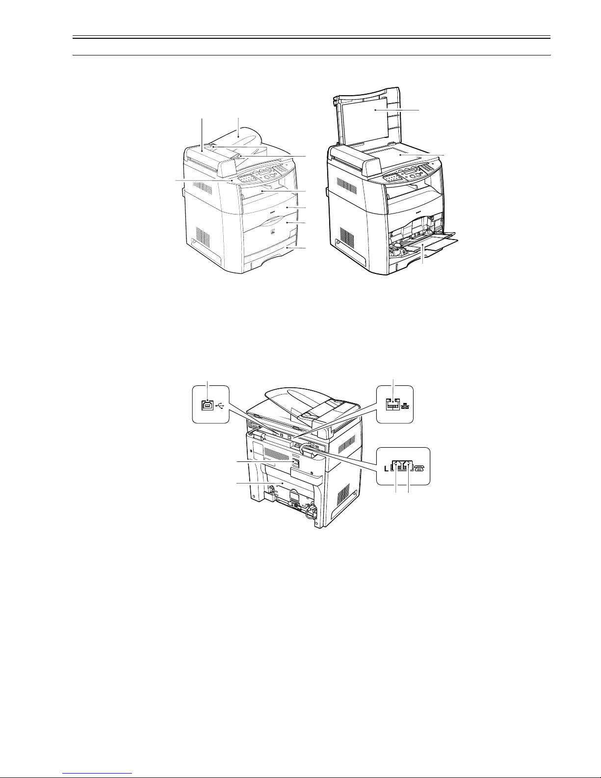
Chapter 1
1-3
1.2 Names of Parts
1.2.1 External View
0007-4608
F-1-1
F-1-2
[1] Operation panel [7] Front cover
[2] ADF (Auto Document Feeder) [8] Cassette
[3] Document feeder tray [9] Platen glass cover
[4] Document guides [10] Platen glass
[5] Output tray [11] Multi-purpose tray
[6] Cartridge cover
[12] USB port [15] Telephone line jack
[13] Power socket [16] External device jack
[14] Face up cover [17] Ethernet port
[1]
[2] [3]
[4]
[5]
[6]
[7]
[8]
[9]
[10]
[11]
LINE EXT.
[12]
[13]
[14]
[15][16]
[17]
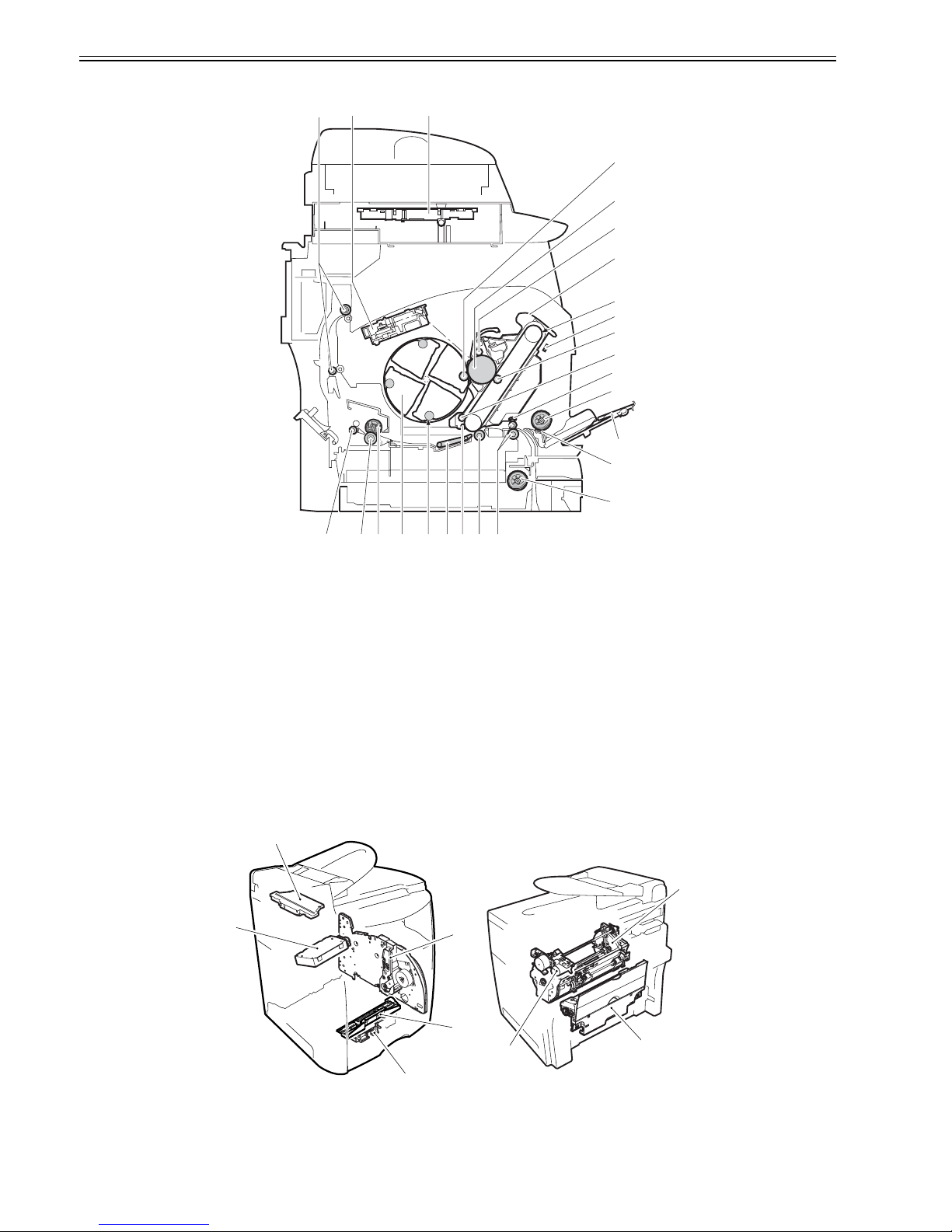
Chapter 1
1-4
1.2.2 Cross Sectional View
0007-4617
F-1-3
1.2.3 Major Unit
0007-4618
F-1-4
[1] Laser/scanner unit [14] Registration roller unit
[2] Developing cylinder [15] Secondary transfer roller
[3] Photosensitive drum [16] Auxiliary ITB cleaning roller
[4] Primary charging roller [17] Feed belt
[5] Drum cartridge [18] Developing rotary
[6] ITB [19] Toner cartridge
[7] Density sensor [20] Fixing film unit
[8] Primary transfer roller [21] Pressure roller
[9] ITB cleaning roller [22] Fixing delivery roller
[10] Registration shutter [23] Facedown delivery roller
[11] Pick-up roller [24] Cassette feeding roller
[12] Multi-purpose tray [25] CCD unit
[13] Separation pad
[1] CCD unit [5] Registration roller assembly
[2] Laser/scanner unit [6] Rotary drive assembly
[10]
[11]
[12]
[13]
[24]
[14]
[15]
[16][17]
[18]
[19]
[20]
[21]
[22]
[6]
[7]
[8]
[9]
[2]
[3]
[4]
[5]
[1]
[23]
[25]
[1]
[2]
[3]
[4]
[5]
[6]
[7]
[8]
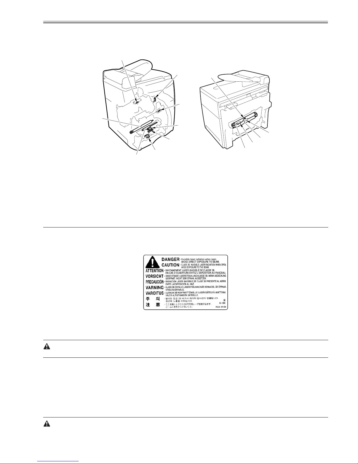
Chapter 1
1-5
1.2.4 Major Component
0007-4619
F-1-5
1.3 Safety
1.3.1 Safety of the Laser Light
0007-4966
Laser light can prove to be hazardous to the human body. The machine's laser unit is fully enclosed in a protective housing and external covers so that its light will
not escape outside as long as the machine is used normally.
F-1-6
1.3.2 Safety of Toner
0007-4969
The machine's toner is a non-toxic material composed of plastic, iron, and small amounts of dye.
Do not put the toner into fire. It may explode.
Toner on the Skin or Clothes
1. If your skin or clothes came into contact with toner, use dry tissue to remove the toner, and then wash with water.
2. Do not use warm or hot water, which will cause the toner to jell, permanently fusing it with the fibers of the clothes.
3. Do not bring toner into contact with vinyl material. They are likely to react with each other.
1.3.3 Safety and Ozone
0007-4970
The cleaning charge roller used in the machine generates ozone gas (O3) at time of corona discharge (only when the machine is in operation).
A set of rules exists under Underwriters' Laboratories (UL) standards for levels of ozone gas permitted, and the machine has been certified to comply with the rules
at time of shipment from the factory.
1.3.4 Points to Note When Replacing/Disposing of the Lithium Battery
0011-0506
RISK OF EXPLOSION IF BATTERY IS REPLACED BY AN INCORRECT TYPE.
[3] Main drive assembly [7] Developing rotary assembly
[4] Registration shutter assembly [8] Fixing assembly
[1] Toner cartridge memory tag contact [8] Thermal fuse
[2] Machine inside temperature thermistor [9] Main thermistor
[3] Multifeeder pickup roller [10] Sub thermistor
[4] Separation pad [11] Fixing film assembly
[5] Registration roller [12] Pressure roller
[6] Secondary toner roller [13] Cassette pickup roller
[7] Drum cartridge memory tag contact
[1]
[2]
[3]
[4]
[13]
[5]
[6]
[7]
[8]
[9]
[10]
[11]
[12]

Chapter 1
1-6
DISPOSE OF USED BATTERIES ACCORDING TO THE INSTRUCTIONS.
1.3.5 CDRH Ordinances
0011-0549
The Center for Devices and Radiological Health (CDRH) of the US Food and Drum Administration put into force ordinances related to laser products on August
2, 1976. These ordinances apply to laser products manufactured on and after August 1, 1976, and sale of laser products is prohibited within the US unless they bear
a certificate of compliance. The following is the label that indicates compliance with the CDRH ordinances, and it must be found on all laser products sold in the US.
F-1-7
The description may vary from model to model.
1.4 Functional Configuration
1.4.1 Functional Construction
0007-4972
The machine may be divided into the following 6 functional blocks: system control block, reader control block, printer control block, laser/scanner block, image
formation block, pickup/feeder block.
The following is a diagram showing these blocks:
F-1-8
1.5 Basic Sequense
1.5.1 Basic Operation Sequence
0008-1692
The operation sequences for the printer are controlled by the CPU in the DCNTboard in the engine control system. The table below indicates the purposes and
engine operations of each period from when the power is turned on until a print operation is completed and each motor stops rotating. See the appendix for the
timing chart.
T-1-1
Period Purpose Remarks
WAIT
(Wait)
From the power switch is
turned on until ITB cleaning
is completed.
To clear a potential on the
drum surface and clean the
ITB.
In this period, the printer executes
residual paper detection, toner level
detection, image density calibration
control, etc.
STBY
(Standby)
From the end of the WAIT
or LSTR period until a print
command is input from the
interface controller or the
power switch is turned off.
To keep the printer ready to
print.
INTR
(Initial
rotation)
After the input of a print
command from the interface
controller until the ITB
HOME POSITION
DETECTION (HP1) signal
for the first color is detected.
To stabilize sensitivity of the
photosensitive drum in
preparation for printing.
System control
system
Laser exposure system
Print control
system
Pickup / feed system
fixing system
Image formation system
Eeposure control system
 Loading...