


MF735C Series
Service Manual
Revision 2.0

1x
1x
Introduction
Introduction
Important Notices
Application
This manual has been issued by Canon Inc. for qualified persons to learn technical theory, installation, maintenance, and repair
of products.
This manual covers all localities where the products are sold. For this reason, there may be information in this manual that does
not apply to your locality.
Corrections
This manual may contain technical inaccuracies or typographical errors due to improvements or changes in products.
When changes occur in applicable products or in the contents of this manual, Canon will release technical information as the
need arises. In the event of major changes in the contents of this manual over a long or short period, Canon will issue a new
edition of this manual.
The following paragraph does not apply to any countries where such provisions are inconsistent with local law.
Trademarks
The product names and company names used in this manual are the registered trademarks of the individual companies.
Copyright
The copyright of this document belongs to Canon Inc. This document may not be copied, reproduced or translated into another
language, in whole or in part, without the prior consent of Canon Inc.
Copyright CANON INC. 2017
Caution
Use of this manual should be strictly supervised to avoid disclosure of confidential information.
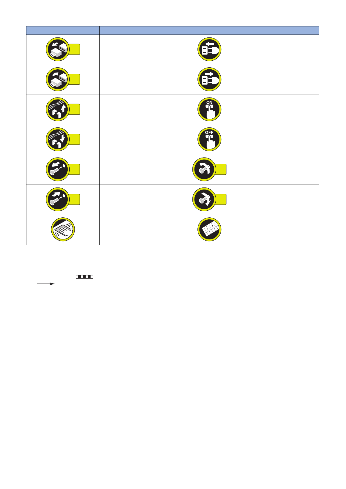
Explanation of Symbols
The following symbols are used throughout this Service Manual.
Symbols Explanation Symbols Explanation
Check.
Remove the claw.
Check visually.
Check a sound. Push the part.
Insert the claw.
1x
1x
1x
1x
1x
1x
1x
1x
Introduction
Symbols Explanation Symbols Explanation
Disconnect the connector. Connect the power cable.
Connect the connector. Disconnect the power cable.
Remove the cable/wire from the
cable guide or wire saddle.
Install the cable/wire to the cable
guide or wire saddle.
Remove the screw.
Install the screw.
Cleaning is needed. Measurement is needed.
The following rules apply throughout this Service Manual:
1. Each chapter contains sections explaining the purpose of specific functions and the relationship between electrical and
mechanical systems with reference to the timing of operation.
In the diagrams, represents the path of mechanical drive; where a signal name accompanies the symbol, the arrow
indicates the direction of the electric signal.
The expression "turn on the power" means flipping on the power switch, closing the front door, and closing the delivery unit
door, which results in supplying the machine with power.
2. In the digital circuits, '1' is used to indicate that the voltage level of a given signal is "High", while '0' is used to indicate "Low".
(The voltage value, however, differs from circuit to circuit.) In addition, the asterisk (*) as in "DRMD*" indicates that the DRMD
signal goes on when '0'.
In practically all cases, the internal mechanisms of a microprocessor cannot be checked in the field. Therefore, the operations
of the microprocessors used in the machines are not discussed: they are explained in terms of from sensors to the input of
the DC controller PCB and from the output of the DC controller PCB to the loads.
The descriptions in this Service Manual are subject to change without notice for product improvement or other purposes, and
major changes will be communicated in the form of Service Information bulletins.
All service persons are expected to have a good understanding of the contents of this Service Manual and all relevant Service
Information bulletins and be able to identify and isolate faults in the machine.
Turn on the power.
Turn off the power.
Loosen the screw.
Tighten the screw.

Contents
Contents
Safety Precautions...............................................................................................1
Laser Safety........................................................................................................................................ 2
How to Handle the Laser Scanner Unit...............................................................................................2
Toner Safety........................................................................................................................................2
About Toner..........................................................................................................................................2
Handling Adhered Toner........................................................................................................................2
Notes When Handling a Lithium Battery............................................................................................. 3
Notes on Assembly/Disassembly........................................................................................................3
1. Product Overview.............................................................................................4
Product Lineup.................................................................................................................................... 5
Host Machine........................................................................................................................................5
Option.................................................................................................................................................. 5
Features...............................................................................................................................................6
Specifications...................................................................................................................................... 7
Specifications of Host Machine.............................................................................................................. 7
Paper type............................................................................................................................................8
Paper size............................................................................................................................................ 9
Parts Name....................................................................................................................................... 10
External view...................................................................................................................................... 10
Cross Section View............................................................................................................................. 12
Control Panel......................................................................................................................................13
2. Technical Explanation (Device).................................................................... 15
Basic Configuration........................................................................................................................... 16
Functional Configuration......................................................................................................................16
Original Exposure/Feed System........................................................................................................17
Original Exposure System....................................................................................................................17
Original Feed System ......................................................................................................................... 19
Laser Exposure System.................................................................................................................... 22
Functional Configuration......................................................................................................................22
Failure Detection.................................................................................................................................22
Controller System..............................................................................................................................24
Configuration/Function.........................................................................................................................24
Main Controller PCB............................................................................................................................25
Motor Control......................................................................................................................................25
Door Open Detection...........................................................................................................................26
Fan Control.........................................................................................................................................26
Low-voltage Power Supply Control.......................................................................................................26
Protection Function............................................................................................................................. 27
Power-saving Mode.............................................................................................................................27
Image Formation System.................................................................................................................. 29
Major Components..............................................................................................................................29
Image Formation Process....................................................................................................................29
i

Contents
High Voltage Power Supply Control......................................................................................................29
Image Stabilization Control.................................................................................................................. 30
Cartridge............................................................................................................................................ 32
Pickup Feed System......................................................................................................................... 35
Overview............................................................................................................................................ 35
Parts Configuration..............................................................................................................................36
Drive Configuration..............................................................................................................................37
Layout of Sensors............................................................................................................................... 38
Lifter Control.......................................................................................................................................38
Cassette Detection..............................................................................................................................39
Cassette Pickup Control...................................................................................................................... 40
Multi-purpose Tray Pickup Control........................................................................................................40
Skew Correction..................................................................................................................................41
Arch Control........................................................................................................................................42
Delivery Tray Full Detection................................................................................................................. 43
Jam Detection.....................................................................................................................................43
Fixing System....................................................................................................................................45
Functional Configuration......................................................................................................................45
Fixing Temperature Control................................................................................................................. 45
Protection Function............................................................................................................................. 46
Fixing Assembly Failure Detection........................................................................................................46
3. Technical Explanation (System)................................................................... 48
Overview of System Management.................................................................................................... 49
Version Upgrade............................................................................................................................... 50
Function Overview.............................................................................................................................. 50
Version Upgrade Using UST................................................................................................................51
Version Upgrade via Internet................................................................................................................51
Version Upgrade Using USB................................................................................................................52
Setting Information Export/Import Function (DCM)........................................................................... 54
Overview............................................................................................................................................ 54
Import/Export Procedure from [Settings/Registration] of Remote UI........................................................ 56
Procedure for Exporting/Importing Service Mode Setting Information......................................................59
List of Items Which Can Be Imported....................................................................................................60
Monitoring Function (e-Maintenance/imageWARE Remote)............................................................ 68
Overview of System............................................................................................................................ 68
Servicing Notes...................................................................................................................................69
Setting Procedure............................................................................................................................... 69
Maintenace.........................................................................................................................................70
4. Periodical Service.......................................................................................... 72
Periodically Replaced Parts.............................................................................................................. 73
Consumable Parts.............................................................................................................................74
Periodical Services............................................................................................................................75
5. Parts Replacement and Cleaning................................................................. 76
List of Parts....................................................................................................................................... 77
Major Units......................................................................................................................................... 77
Layout Drawing of Electrical Components.............................................................................................79
ii

Contents
External Cover System......................................................................................................................85
Removing the Toner Cartridge............................................................................................................. 85
Removing the Left Cover..................................................................................................................... 86
Removing the Right Cover...................................................................................................................88
Removing the Rear Cover Unit.............................................................................................................90
Removing the Cartridge Cover ............................................................................................................ 91
Removing the Cartridge Tray............................................................................................................... 93
Removing the Upper Front Cover.........................................................................................................94
Removing the Upper Left Front Cover.................................................................................................. 95
Removing the Upper Right Front Cover................................................................................................ 95
Removing the Upper Cover Unit ..........................................................................................................96
Original Exposure/Feed System........................................................................................................97
Removing the ADF Unit + Reader Unit................................................................................................. 97
Separating the ADF Unit + Reader Unit................................................................................................ 98
Removing the ADF Roller Unit............................................................................................................100
Removing the ADF Pickup Roller....................................................................................................... 102
Removing the ADF Separation Roller................................................................................................. 103
Removing the ADF Separation Pad Unit............................................................................................. 105
Removing the ADF Upper Cover Unit................................................................................................. 106
Removing the ADF Feed Unit.............................................................................................................107
Removing the ADF CIS (For the duplex scanning model).....................................................................108
Removing the ADF Drive Unit............................................................................................................ 112
Removing the Reader Upper Cover Unit............................................................................................. 114
Removing the Reader CIS................................................................................................................. 115
Removing the Reader CIS Timing Belt................................................................................................118
Removing the Reader Scanner Motor.................................................................................................118
Controller System............................................................................................................................120
Removing the Controller Cover ..........................................................................................................120
Removing the Wireless LAN PCB (Wi-Fi model only)...........................................................................121
Removing the Wireless LAN Support Plate (Wi-Fi model only)............................................................. 121
Removing the Main Controller PCB.................................................................................................... 122
Removing the Main Controller Support Plate.......................................................................................122
Removing the Engine Controller PCB................................................................................................. 123
Removing the Low Voltage Power Supply Unit.................................................................................... 123
Removing the Control Panel Unit........................................................................................................125
Removing the OFF Hook PCB (Fax model only)..................................................................................127
Removing the NCU PCB (Fax model only)..........................................................................................128
Removing the Speaker (Fax model only).............................................................................................128
Removing the USB PCB.................................................................................................................... 129
Removing the Cartridge Fan.............................................................................................................. 130
Removing the Power Supply Fan....................................................................................................... 131
Removing the Driver PCB.................................................................................................................. 132
Removing the Power Switch Unit........................................................................................................133
Removing the Environment Sensor.....................................................................................................133
Removing the Memory Relay PCB..................................................................................................... 134
Laser Exposure System.................................................................................................................. 136
Removing the Laser Scanner Unit...................................................................................................... 136
Image Formation System................................................................................................................ 142
Removing the Secondary Transfer Roller............................................................................................142
Removing the Secondary Transfer Feed Unit...................................................................................... 143
Removing the ITB Unit.......................................................................................................................144
iii

Contents
Removing the Color Displacement Density Sensor Unit....................................................................... 146
Removing the Developing Motor.........................................................................................................147
Removing the Drum Motor................................................................................................................. 149
Fixing System..................................................................................................................................151
Removing the Fixing Assembly.......................................................................................................... 151
Removing the Fixing Power Supply Unit............................................................................................. 153
Removing the Fixing Motor................................................................................................................ 154
Pickup Feed Delivery System......................................................................................................... 155
Removing the Cassette Pickup Roller/Feed Roller Unit ....................................................................... 155
Removing the Cassette Separation Roller Unit ................................................................................... 156
Removing the Duplex Reverse Drive Unit........................................................................................... 158
Removing the Pickup Motor............................................................................................................... 159
Removing the Re-Pickup Unit............................................................................................................ 160
Removing the Lifter Drive Unit............................................................................................................162
Removing the Cassette Pickup Unit....................................................................................................164
Removing the Multi-purpose Tray Pickup Roller.................................................................................. 166
Removing the Multi-purpose Tray Separation Pad............................................................................... 167
Removing the Registration Unit.......................................................................................................... 168
6. Adjustment................................................................................................... 172
Adjustment at Parts Replacement...................................................................................................173
After Replacing the Control Panel.......................................................................................................173
After Replacing the ITB Unit...............................................................................................................173
After Replacing the Color Displacement Density Sensor Unit............................................................... 173
Engine Controller PCB.......................................................................................................................173
Main Controller PCB..........................................................................................................................173
After Replacing the ADF Unit............................................................................................................. 179
After Replacing the Reader CIS Unit...................................................................................................182
After Replacing the Reader Upper Cover Unit..................................................................................... 186
After Replacing the Reader Unit......................................................................................................... 191
After Replacing the ADF CIS Unit.......................................................................................................198
7. Troubleshooting...........................................................................................202
Test Print.........................................................................................................................................203
Engine Test Print...............................................................................................................................203
Controller test print............................................................................................................................ 204
Cartridge Log Report......................................................................................................................... 214
Troubleshooting Items.....................................................................................................................216
Recurring faulty image.......................................................................................................................216
Confirming nip width..........................................................................................................................216
Action When Hue Differs between the Front and Back Sides of the Output Image at Duplex Copy
(For the duplex scanning ADF model)............................................................................................. 217
Debug Log.......................................................................................................................................219
Function Overview.............................................................................................................................219
Conditions for collecting logs..............................................................................................................219
Collection procedure..........................................................................................................................219
8. Error/Jam/Alarm........................................................................................... 221
Overview......................................................................................................................................... 222
iv

Contents
Error/Jam/Alarm Log indication.......................................................................................................... 222
JAM/ERR LOG REPORT...................................................................................................................223
Location Code...................................................................................................................................224
Pickup Position Code.........................................................................................................................224
Error Code.......................................................................................................................................225
Error Code Details.............................................................................................................................225
Jam Code........................................................................................................................................232
Jam Code Details..............................................................................................................................232
Alarm Code..................................................................................................................................... 235
Alarm Code Details........................................................................................................................... 235
9. Service Mode................................................................................................ 236
Overview......................................................................................................................................... 237
Entering Service Mode...................................................................................................................... 237
Service Label....................................................................................................................................237
Remote UI Service Mode...................................................................................................................237
COPIER (Service mode for copier)................................................................................................. 240
DISPLAY (State display mode)...........................................................................................................240
I/O (I/O display mode)........................................................................................................................242
ADJUST (Adjustment mode).............................................................................................................. 243
FUNCTION (Operation / inspection mode).......................................................................................... 285
OPTION (Specification setting mode)................................................................................................. 302
COUNTER (Counter mode)............................................................................................................... 314
FEEDER (ADF service mode).........................................................................................................320
ADJUST (Adjustment mode).............................................................................................................. 320
FUNCTION (Operation / inspection mode).......................................................................................... 321
FAX (FAX service mode).................................................................................................................322
SSSW (Bit switch registration mode).................................................................................................. 322
MENU (Menu switch registration mode).............................................................................................. 323
NUM (Numeric parameter setting mode).............................................................................................323
NCU (NCU parameter setting mode).................................................................................................. 324
TESTMODE (Service mode for test print, operation check, etc.)....................................................328
PRINT (Print test mode).....................................................................................................................328
FAX (FAX test mode).........................................................................................................................332
10. Installation.................................................................................................. 337
Copy Control Interface Kit-C1......................................................................................................... 338
Points to Note at Installation...............................................................................................................338
Installation Outline Drawing................................................................................................................338
Checking the Contents...................................................................................................................... 338
Check Item When Turning OFF the Main Power..................................................................................338
Installation Procedure........................................................................................................................338
MiCARD Attachment Kit-B1............................................................................................................ 345
Points to Note at Installation...............................................................................................................345
Installation Outline Drawing................................................................................................................345
Checking the Contents...................................................................................................................... 345
Check Item When Turning OFF the Main Power..................................................................................345
Installation Procedure........................................................................................................................345
Copy Card Reader-F1.....................................................................................................................351
v

Contents
Points to Note at Installation...............................................................................................................351
Installation Outline Drawing................................................................................................................351
Checking the Contents...................................................................................................................... 351
Check Item When Turning OFF the Main Power..................................................................................351
Installation Procedure........................................................................................................................352
Setting after Installation..................................................................................................................... 362
APPENDICES....................................................................................................363
Service Tools...................................................................................................................................364
Special Tools.................................................................................................................................... 364
Solvents and Oil List..........................................................................................................................364
General Circuit Diagram..................................................................................................................365
Backup Data List............................................................................................................................. 368
Soft counter specifications.............................................................................................................. 370
vi

Safety Precautions
Laser Safety..........................................2
How to Handle the Laser Scanner Unit
...........................................................2
Toner Safety..........................................2
Notes When Handling a Lithium
Battery............................................... 3
Notes on Assembly/Disassembly..........3
Safety Precautions
Laser Safety
Since radiation emitted inside this machine is completely confined with protective housings and external covers, the laser beam
cannot escape from the machine during any phase of normal use by users.
Therefore, this machine is classified as a Class 1 laser product under the international standard IEC60825-1 that is regarded as
safe during normal use.
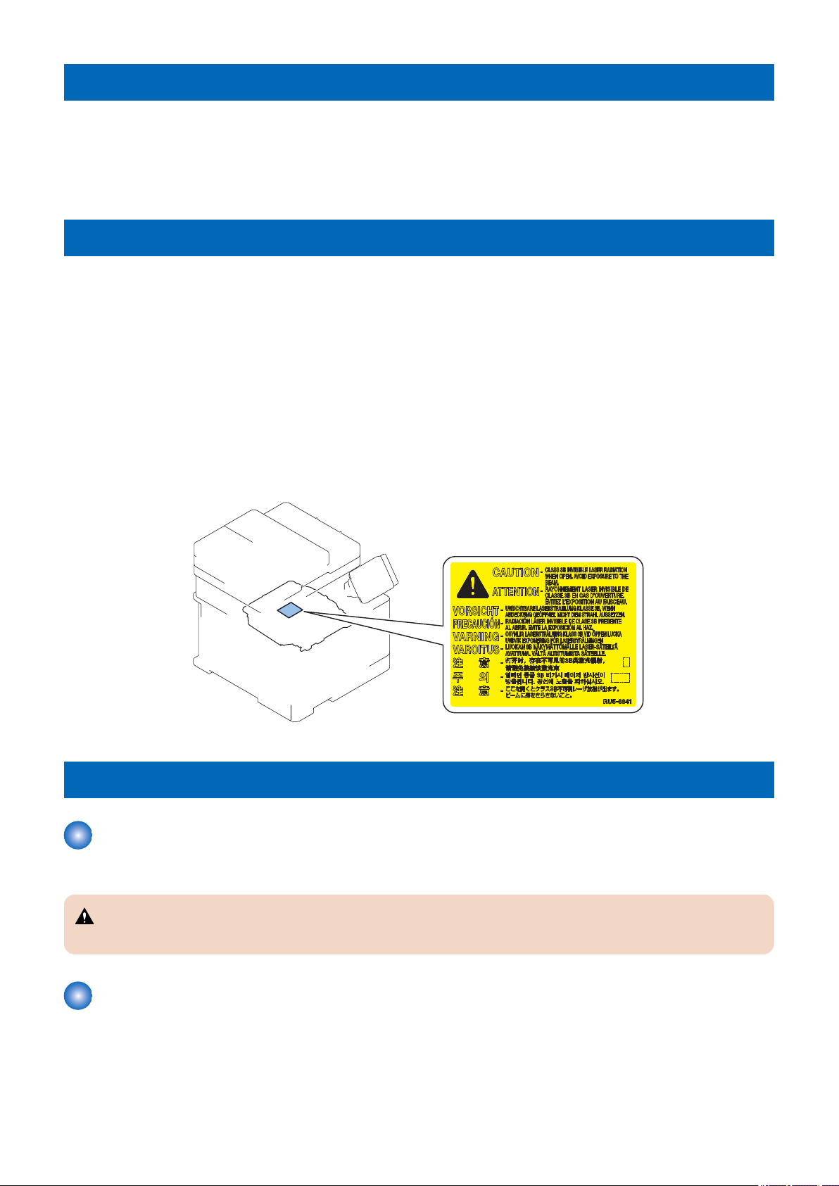
How to Handle the Laser Scanner Unit
This machine is classified as a Class 1 laser product.
However, the laser scanner unit contains source of Class 3B laser beam and exposure to the beam may cause eye injuries.
Therefore, be sure not to disassemble the laser scanner unit. No adjustment can be made to the laser scanner unit in the machine
in the field.
The label shown in the following figure is affixed on the laser scanner unit.
Dieses Gerät ist der Klasse 1 der Laserprodukte zugeordnet.
Allerdings enthält die Laserscannereinheit eine Laserstrahlquelle der Klasse 3B, die Augenschäden verursachen kann, wenn
man in diesen Strahl blickt.
Deshalb darf die Laserscannereinheit nicht zerlegt werden. An der Laserscannereinheit kann keine Justage vor Ort vorgenommen
werden.
Der in folgendem Bild dargestellte Aufkleber ist auf der Laserscannereinheit angebracht.
Toner Safety
About Toner
Toner is a nontoxic matter composed of plastic, iron and a trace of pigments.
CAUTION:
Never throw toner in flames to avoid explosion.
Handling Adhered Toner
• Use dry tissue paper to wipe off toner adhered to skin or clothes and wash in water.
• Never use warm water for cleaning up toner to prevent toner particles from being gelated to soak into fibers permanently.
• Toner particles are reactive with vinyl polymers. Avoid contacting these materials.
2
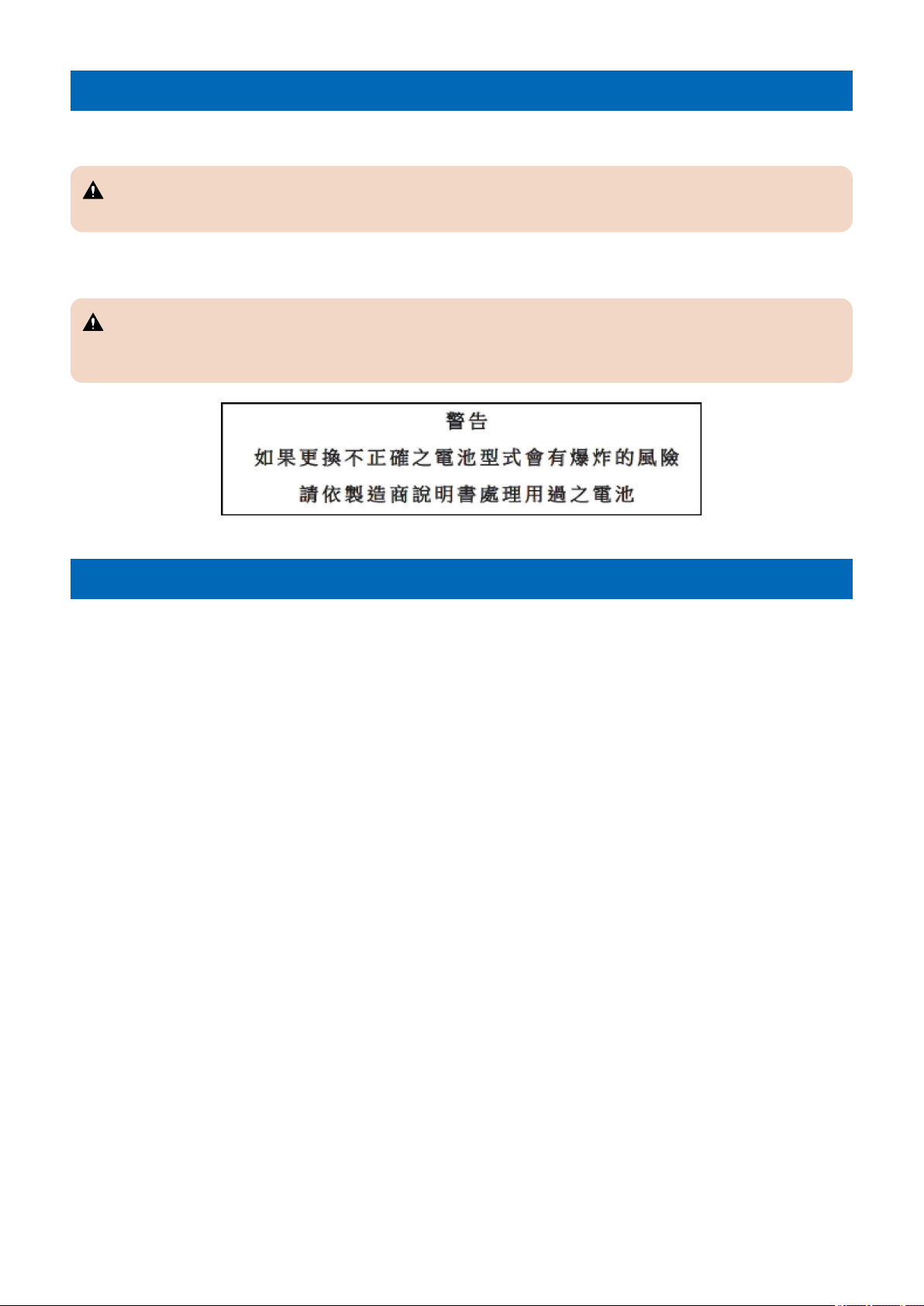
Notes When Handling a Lithium Battery
Dispose of used batteries according to the instructions.
CAUTION:
Risk of explosion if battery is replaced by an incorrect type.
The following warnings are given to comply with Safety Principles (EN60950-1).
CAUTION:
Wenn mit dem falschen Typ ausgewechselt, besteht Explosionsgefahr.
Gebrauchte Batterien gemäß der Anleitung beseitigen.
Safety Precautions
Notes on Assembly/Disassembly
Follow the items below to assemble/disassemble the device.
1. Disconnect the power plug to avoid any potential dangers during assembling/disassembling works.
2. If not specially instructed, reverse the order of disassembly to reinstall.
3. Ensure to use the right screw type (length, diameter, etc.) at the right position when assembling.
4. To keep electric conduction, binding screws with washers are used to attach the grounding wire and the varistor. Ensure to
use the right screw type when assembling.
5. Unless it is specially needed, do not operate the device with some parts removed.
6. Never remove the paint-locked screws when disassembling.
3

1
Product Overview
Product Lineup......................................5
Specifications........................................7
Parts Name......................................... 10

Product Lineup
Host Machine
MF735Cdw /MF735Cx
Copy Yes
Print Yes
Fax Yes
Remote UI Yes
ADF 2-sided scanning
2-sided printing Yes
Control Panel 5 inch Touch Panel
NFC Yes
Backup of counter Yes
MEAP -
Network Yes
Wireless LAN Yes
1. Product Overview
PDL
MF735Cdw / MF735Cx
PS Yes
PCL Yes
Option
Name Description
Cassette Feeding Module-AF1 550 sheets (80 g/m2) of paper can be placed
Copy Card Reader Attachment-J1 Except KOR model
Copy Control Interface Kit-C1 Except KOR model
Copy Card Reader-F1 Except KOR model
MiCARD Attachment Kit-B1 Attachment kit for MiCARD Reader
Except KOR model
HANDSET KIT 3 Long cord Cool White AE model only
TELEPHONE 6 KIT Long cord Cool White EUR/TWN model only
Barcode Printing Kit-E1 Except KOR model
Send PDF Security Feature Set-E1
5

1. Product Overview
Features
Middle Class A4/LTR Color Laser MFP
1. Improved Control Panel operability
Improved operability by adopting the Large 5 inch Color Touch Panel.
2. 1-path simultaneous duplex reading
Increased productivity in 2-sided original reading by adopting the 1-path ADF (Scan, Send, Copy).
3. Support for mobile print
Printing from smartphones, tablets and PCs via an application such as Apple AirPrint, proprietary application, Google Cloud
Print and Mopria Print becomes available.
4. Support for wireless LAN
Communication via mobile device and wireless LAN becomes available by connecting a wireless LAN router to the network
to which this machine is connected.
5. NFC (Near Field Communication)
Printing can be performed by touching a mobile device where Canon PRINT Business is installed.
6

Specifications
Specifications of Host Machine
Item Specification / Function
Copyboard Fixed
Device Installation Desktop
Light source LED (RGB)
Photoreceptor OPC drum (φ24)
Image scanning CIS (color)
Light exposure method Laser beam exposure
Charging method Roller charging
Developing method Contact development
Transfer method Primary transfer: Sequential 4 colors transfer to Intermediate Transfer Belt
Secondary transfer: 4-color batch transfer onto the transfer material by the Transfer Roller
Separation method Curvature separation
Cassette paper feed Simple separation retard
MP Tray paper feed Pad separation method
Drum cleaning method Cleaning blade
Transfer cleaning method Cleaning brush and roller
Fixing method On-demand fixing
Paper delivery method Face-down
Toner level sensor Mounted
Toner type Non-magnetic one-component toner
Toner supply method All-in-one cartridge (drum + toner)
Toner save mode N/A
Document types Sheet / book
Maximum document size Copyboard Glass: 216 mm × 297 mm
Feeder: 216 mm × 356 mm
Document size sensor N/A
Image size magnification Zoom: 25 to 400% (1% increment)
Warm-up Time *1 13 seconds or less
Recovery Time *2 Approx. 6.1 seconds
Reading resolution 600 x 600 dpi (Maximum)
Reading Speed Fixed (A4/LTR):
• N/A
Continuous reading, SEND:
• Color: 10 images / minute (A4/LTR)
• B&W: 20 images / minute (A4)
• B&W: 21 images / minute (LTR)
Print resolution 600 x 600 dpi
First copy time Color: Approx. 11.3 seconds(A4), Approx. 11.1 seconds(LTR)
B&W: Approx. 9.8 seconds(A4), Approx. 9.5 seconds(LTR)
First print time Color: Approx. 8.6 seconds(A4), Approx. 8.5 seconds(LTR)
B&W: Approx. 8.3 seconds(A4), Approx. 8.1 seconds(LTR)
Print Speed *3 At 1-sided printing:
• Color/B&W: Approx. 27 sheets/min.(A4), Approx. 28 sheets/min.(LTR)
At 2-sided printing:
• Color/B&W: Approx. 21.9 sheets/min.(A4), Approx. 23.1 sheets/min.(LTR)
Available paper type for cassette
Available paper type for Multi-purpose Tray
Available paper size in cassette
Thin paper, Recycled paper, Color paper, Plain paper, Heavy paper, Coated paper, Label, Envelope
(Refer to “Paper type” on page 8)
Thin paper, Recycled paper, Color paper, Plain paper, Heavy paper, Coated paper, Label, Envelope
(Refer to “Paper type” on page 8)
A4, B5, A5, LGL, LTR, STMT, EXEC, OFFICIO, B-OFFICIO, M-OFFICIO, GLTR, GLGL, FLS, AFLS,
indLGL, K16, Postcard, Envelopes (COM10, Monarch, Nagagata 3, Yougatanaga 3, C5, DL), Custom
Paper Size
(Refer to “Paper size” on page 9)
1. Product Overview
7

1. Product Overview
Item Specification / Function
Multi-purpose tray paper size A4, B5, A5, LGL, LTR, STMT, EXEC, OFFICIO, B-OFFICIO, M-OFFICIO, GLTR, GLGL, FLS, AFLS,
indLGL, K16, Envelopes (COM10, Monarch, Nagagata 3, Yougatanaga 3, C5, DL), Custom Paper Size
(Refer to “Paper size” on page 9)
Cassette capacity
Multi-purpose Tray capacity
Delivery tray stacking capacity *4
Continuous copying 1 to 99 sheets
Automatic 2-sided Available (A4, B5, LGL, LTR, EXEC, FLS)
Memory capacity 1 GB
Sleep mode Available
Allowable environmental
temperature
Allowable humidity 20 to 80% in relative humidity (no condensation)
Power rating Rated input voltage:
Maximum power consumption
Average power at operation 120 V : Approx. 520 W
Average power at standby 120 V : Approx. 20.6 W
Average power at sleep
mode
Power consumption at Main
Power Switch OFF
Dimensions (W x D x H) 471 × 469 × 460 mm
Weight
(Excluding toner cartridges)
Cassette: 250 sheets (60 to 90 g/m2)
Option: 550 sheets (60 to 90 g/m2)
50 sheets (60 to 90 g/m2)
150 sheets (75 g/m2)
10 to 30 deg C
120 V system: 120 to 127 V (60Hz)
200 V system: 220 to 240 V (50/60Hz)
1500 W or lower
230 V : Approx. 560 W
230 V : Approx. 17.7 W
Approx. 1.0 W
0.3 W or lower
Approx. 26.5 kg
*1 : Warm-up time is an interval between when the machine is turned ON and when the main screen appears on the display.
Warm-up time may vary depending on the use conditions and environment of the machine.
*2 : Time for recovery from sleep to standby.
*3 : The print speed may become lower depending on the settings such as output resolution, paper size, type, orientation, and
number of sheets printed. In the case of 2-sided printing, 1 page on the front side and 1 page on the back side are output as
1 sheet.
*4 : The actual stack capacity varies depending on the site environment and the type of paper used.
Paper type
(Yes: Pickup possible -: Pickup not possible)
Type of paper Paper set-
tings in this
machine
Thin paper 60 to 70 g/m2 Thin 1 Yes Yes Yes
60 g/m2 Thin 2 *1 Yes Yes Yes
52 to 59 g/m2 Thin 3 Yes - -
Recycled 60 to 75 g/m2 Recycled 1 Yes Yes Yes
71 to 82 g/m2 Recycled 2 Yes Yes Yes
Color 71 to 82 g/m2 Color Yes Yes Yes
Plain 71 to 82 g/m2 Plain 1 Yes Yes Yes
83 to 90 g/m2 Plain 2 Yes Yes Yes
Heavy paper 91 to 119 g/m2 Heavy 1 Yes Yes Yes
120 to 128 g/m2 Heavy 2 Yes Yes Yes
Standard Cassette/
Cassette Feeding
Module-AF1 (option)
Multi-purpose Tray Auto 2-sided printing
8

1. Product Overview
Type of paper Paper set-
tings in this
machine
Heavy paper
Coated 100 to 120 g/m2 Coated 1 Yes Yes Yes
Label paper Label paper Yes Yes -
Envelope (Nagagata 3, Yougatanaga 3,
C5)
Envelope (COM10, Monarch, DL) Envelope 2 Yes Yes -
129 to 163 g/m2 Heavy 3 Yes Yes Yes
121 to 150 g/m2 Coated 2 Yes Yes Yes
151 to 200 g/m2 Coated 3 Yes Yes Yes
Envelope 1 Yes Yes -
Standard Cassette/
Cassette Feeding
Module-AF1 (option)
Multi-purpose Tray Auto 2-sided printing
*1: When the paper of 60 g/m2 is curled while <Thin 1> is set, select <Thin 2>.
Paper size
(Yes: Pickup possible -: Pickup not possible)
Paper size Standard Cassette/
Cassette Feeding Mod-
ule-AF1 (option)
A4 210.0 mm x 297.0 mm Yes Yes Yes
B5 182.0 mm x 257.0 mm Yes Yes Yes
A5 148.0 mm x 210.0 mm Yes Yes -
LGL 215.9 mm x 355.6 mm Yes Yes Yes
LTR 215.9 mm x 279.4 mm Yes Yes Yes
STMT 139.7 mm x 215.9 mm Yes Yes -
EXEC 184.2 mm x 266.7 mm Yes Yes Yes
OFFICIO*4 215.9 mm x 317.5 mm Yes Yes Yes
B-OFFICIO*4 216 mm x 355 mm Yes Yes Yes
M-OFFICIO*4 216 mm x 341 mm Yes Yes Yes
G-LTR*4 203.2 mm x 266.7 mm Yes Yes Yes
G-LGL*4 203.2 mm x 330.2 mm Yes Yes Yes
FLSC 215.9 mm x 330.2 mm Yes Yes Yes
AFLS*4 206 mm x 338 mm Yes Yes Yes
Indian LGL*4 215.0 mm x 345.0 mm Yes Yes -
Envelope No.10
(COM10)
Envelope Monarch 98.4 mm x 190.5 mm Yes Yes -
Envelope C5 162.0 mm x 229.0 mm Yes Yes -
Envelope DL 110.0 mm x 220.0 mm Yes Yes -
Custom paper - Yes *1 Yes *2 Yes *3
104.7 mm x 241.3 mm Yes Yes -
Multi-purpose Tray Auto 2-sided printing
*1: 100 × 148 mm to 215.9 × 355.6 mm
*2: 676.2 × 127 mm to 215.9 × 355.6 mm
*3: 176 × 250 mm to 215.9 × 355.6 mm
*4: Only when the user-defined size is configured on the driver
9
Parts Name
[1]
[3]
[2]
[5]
[6]
[7]
[8]
[10]
[9]
[4]
[11]
[12]
[13]
[5]
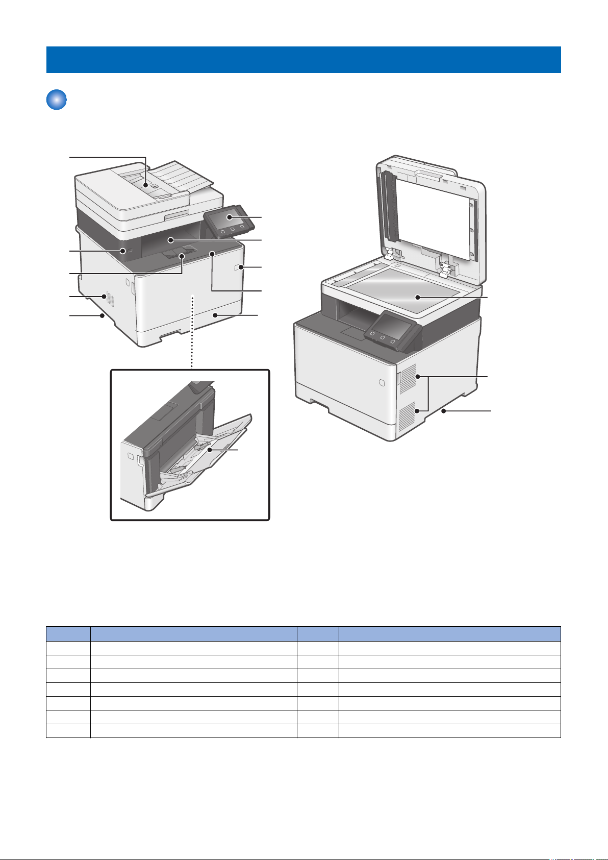
External view
■ Front side of the machine
1. Product Overview
No. Name No. Name
1 Feeder 8 Power Switch
2 USB port (for USB device) 9 Front Cover
3 Delivery Stopper 10 Pickup Cassette
4 Speaker 11 Multi-purpose Tray
5 Handle for carrying 12 Copyboard Glass
6 Control Panel 13 Ventilation hole
7 Delivery Tray
10
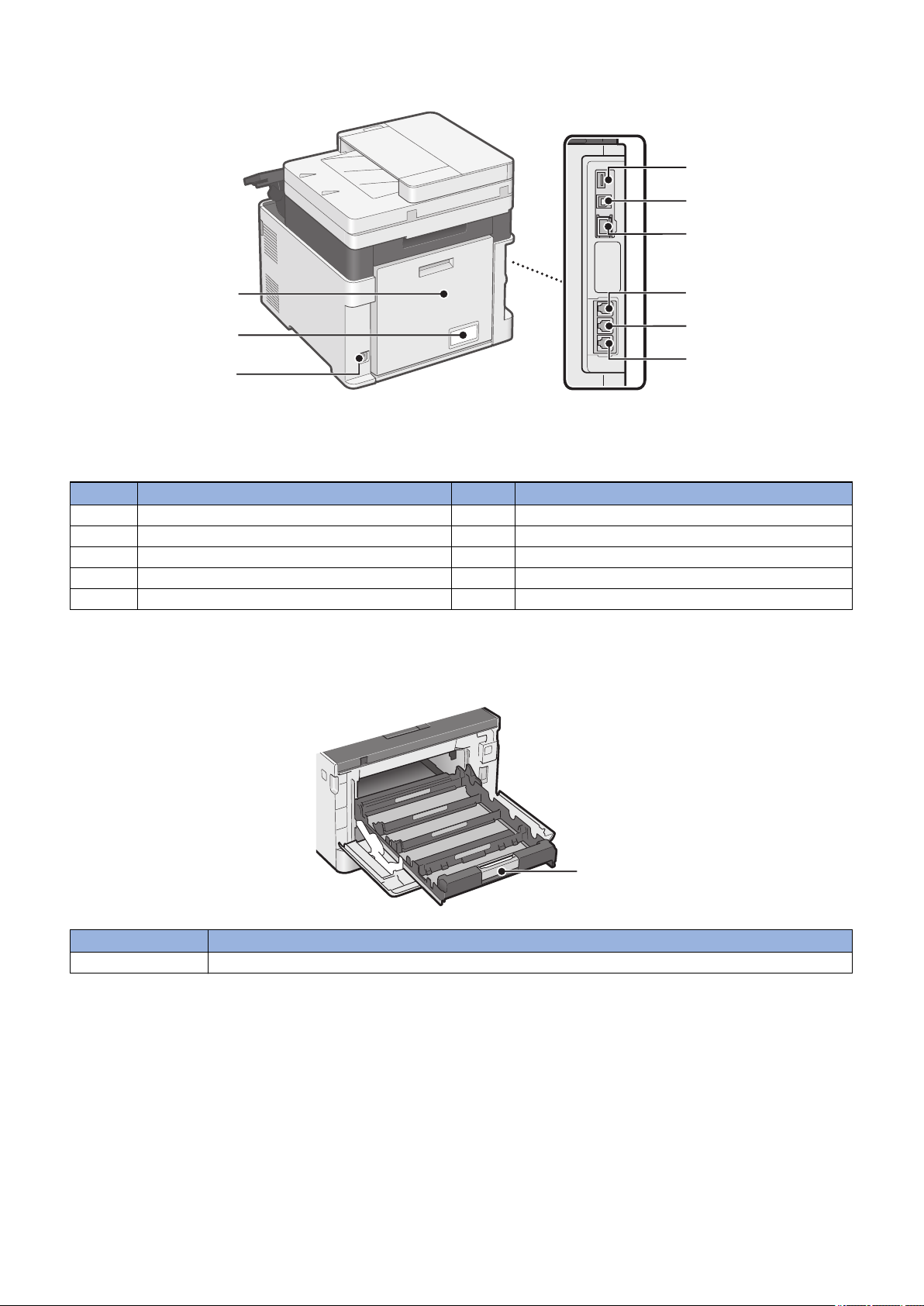
■ Rear side of the machine
[2]
[4]
[5]
[6]
[7]
[8]
[9]
[3]
[1]
[1]
1. Product Overview
No. Name No. Name
1 Rear Cover 6 LAN Port
2 Rating name plate label 7 Terminal for Handset
3 Power Socket 8 Terminal for external telephone
4 USB port (for USB device) 9 Terminal for telephone line
5 USB port (for PC)
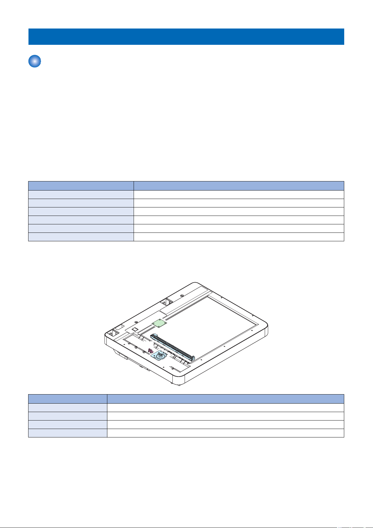
■ Inside of the host machine
No. Name
1 Toner Cartridge Tray
11
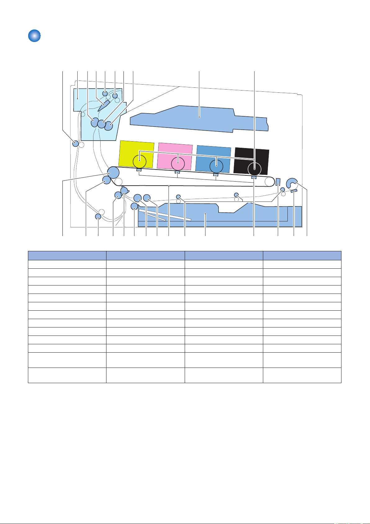
Cross Section View
[10][1] [2] [3] [4] [5] [6] [7] [8] [9]
[11][12][13]
[15]
[16][17][18][19][20][21][22][23][24][25] [14]
■ Host machine
1. Product Overview
No. Name No. Name
[1] Duplex Feed Roller [14] Primary Transfer Brush
[2] Fixing Assembly [15] Cassette
[3] Pressure Film [16] Multi-purpose Tray Feed Roller
[4] Duplex Flapper [17] ITB
[5] Duplex Reverse Roller [18] Cassette Pickup Roller
[6] Delivery Roller [19] Cassette Feed Roller
[7] Fixing Roller [20] Cassette Separation Roller
[8] Fixing Film [21] Registration Shutter
[9] Laser Scanner Unit [22] Registration Roller
[10] Photosensitive Drum [23] Duplex Re-pickup Roller
[11] Multi-purpose Tray Pickup Roller [24] Secondary Transfer Roller
[12] Multi-purpose Tray Separation
Pad
[13] Color Displacement/Density
Sensor
[25] ITB Drive Roller
12
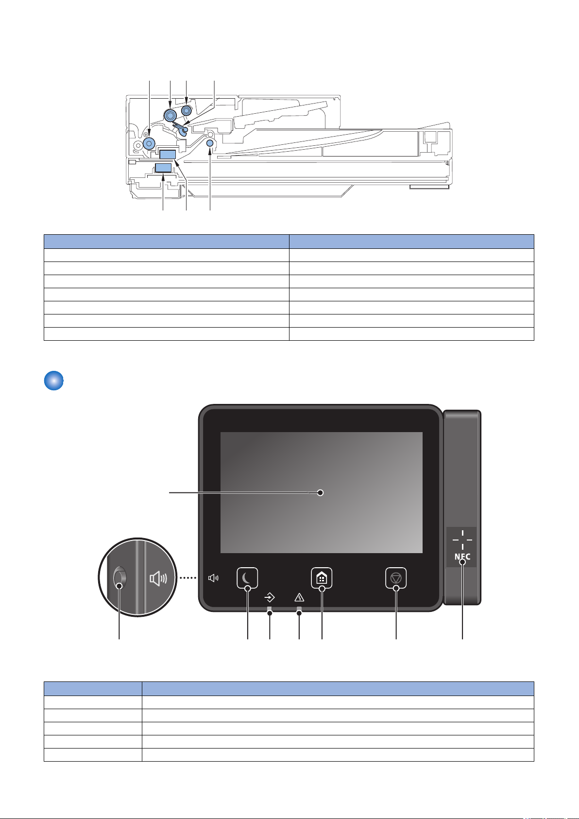
■ ADF/Reader Unit
[1]
[5][7]
[2] [3] [4]
[6]
[3]
[2]
[4] [5] [6] [7]
[8]
[1]
1. Product Overview
No. Name
[1] Feed Roller
[2] Separation Roller
[3] Pickup Roller
[4] Separation Pad
[5] Delivery Roller
[6] Contact Image Sensor (back side)
[7] Contact Image Sensor (front side)
Control Panel
No. Name
1 Display
2 Volume key
3 Energy Saver key
4 Data Lamp
5 Error Lamp
13

No. Name
6 Home key
7 Stop key
8 NFC (Near Field Communication) mark
1. Product Overview
14

Technical
2
Explanation
(Device)
Basic Configuration.............................16
Original Exposure/Feed System......... 17
Laser Exposure System......................22
Controller System................................24
Image Formation System....................29
Pickup Feed System........................... 35
Fixing System......................................45
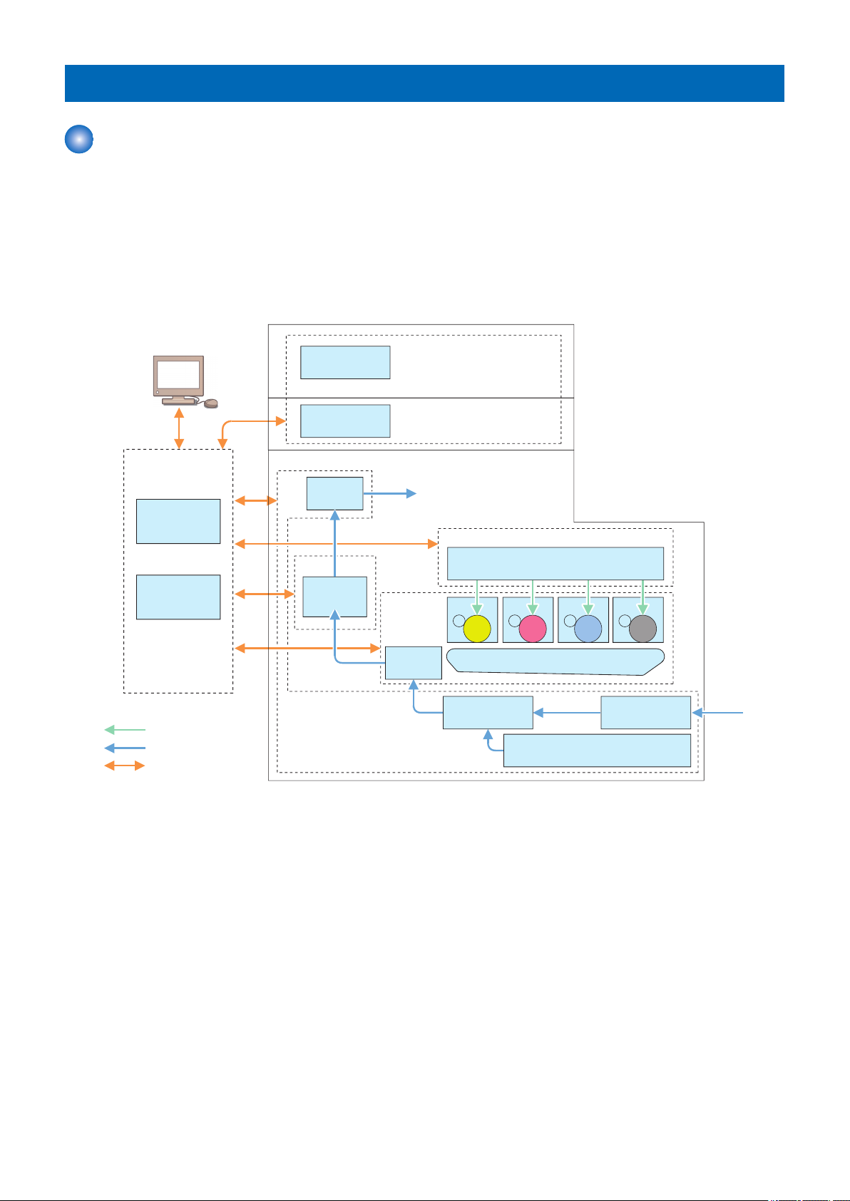
Basic Configuration
Laser beam
Paper flow
Signal flow
CIS unit
ADF
Document exposure/
feeding system
Main
controller
DC
controller
Controller system
Laser scanner
Laser exposure system
ITB unit
Secondary
Transfer
Image
formation
system
Cassette
Manual feed
pickup unit
Pickup
unit
Pickup/feed system
Fixing
assembly
Fixing system
Delivery
assembly
Drum Drum Drum Drum
Functional Configuration
Description
This machine is roughly composed of the following six blocks.
• Original Exposure/Feed System
• Laser Exposure System
• Controller System
• Image Formation System
• Pickup Feed System
• Fixing System
2. Technical Explanation (Device)
16
UN40
CIS
SR11
M5
2. Technical Explanation (Device)
Original Exposure/Feed System
Original Exposure System
■ Functional Configuration
Description
The original on the Copyboard Glass is read by moving the Contact Image Sensor (CIS) by rotating the Reader Motor based on
the drive signal from the Main Controller PCB.
When using the ADF, the original is read by feeding it using the ADF, without moving the Contact Image Sensor.
Simultaneous duplex scanning models have 2 Contact Image Sensors, and the front and back sides of paper are scanned at the
same time with one feed of the paper.
* This model is not included in the lineup of some of the series. (Reference: “Product Lineup” on page 5)
■ Specifications
Description
Item Specification/Function
Photo conductor LED
Reading resolution 600 dpi x 600 dpi
Number of gradations 256 gradations
Magnification ratio 25 % to 400 % (in 1% increment)
Reading Sensor 1 line
Original size detection None
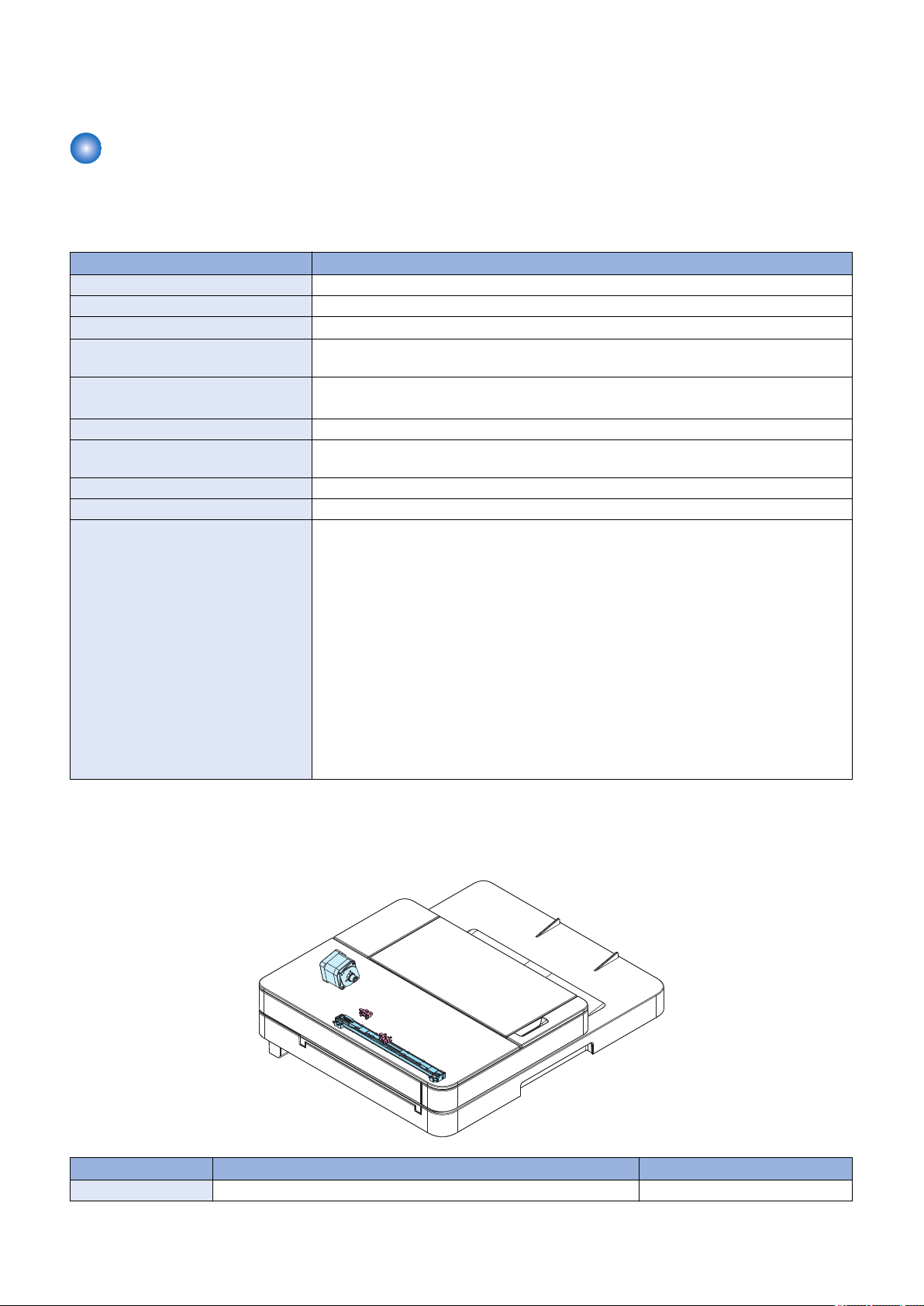
■ Major Components
Description
Symbol Name
M5 Reader Motor
CIS Contact Image Sensor
SR11 CIS HP Sensor
UN40 Connecting Relay PCB
■ Dust Detection Control
Overview
Presence/absence of dust on the Stream Reading Glass is detected when an original is read. In accordance with the detection
result, the original reading position is changed or image correction is performed to prevent the dust from being printed on the
image.
17
B A C
0.5 mm
0.5 mm
2. Technical Explanation (Device)
Control of dust detection consists of the following two items:
• Dust detection correction
• Dust detection evasion
Execution Condition/Timing
Dust detection correction
During the period of time from the moment when the original of a stream reading job arrives just before the reading position
to the moment when reading of the original is completed (for each page)
Dust detection evasion
When a job starts
Description
Dust detection correction
If dust on the Stream Reading Glass is detected, the image is corrected to prevent the dust from being printed.
1. Before the original arrives, the White Plate is read through the Stream Reading Glass, and points where dust may exist
are detected.
2. The leading edge of the original is detected.
3. The detection results before and after the leading edge of the original appears on the Stream Reading Glass are
compared. If dust does not exist at the dust point detected in step 1, it is judged to be dust on the White Plate and dust
correction is not performed. If dust exists at the point detected in step 1, it is judged to be dust on the Stream Reading
Glass and dust correction is performed.
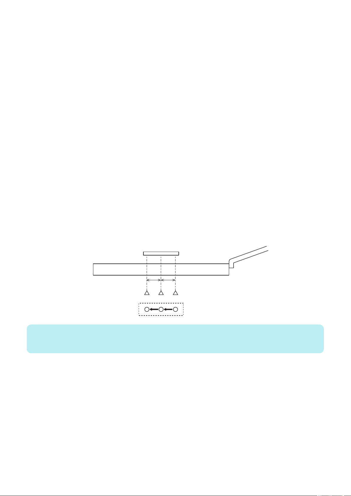
Dust detection evasion
If dust is detected when the last job paper is read, the reading position of the next stream reading job is changed in order to
avoid the dust.
The amount of adjustment for dust evasion is -0.5 mm (B), 0 mm (A), and +0.5 mm (C).
Each time dust is detected when reading the last paper of a stream reading job, the CIS moves to the three positions in the
order shown below.
A -> B -> C -> A ->
NOTE:
In the case of simultaneous duplex scanning models, this control is applied only to reading of the front side where the CIS can be
moved.
If any of the following conditions is detected 6 times in a row, it is judged that the Stream Reading Glass is soiled, and a message
prompting the user to clean the Stream Reading Glass is displayed on the Control Panel.
• Dust of 1 pixel or larger and smaller than 5 pixels is detected at 11 points or more.
• Dust of 5 pixels or larger is detected at 1 point or more.
Service Mode
• Adjustment of the image correction level at stream reading [front]
COPIER > OPTION > BODY > DFDST-L1
• Adjustment of the image correction level at stream reading [back]
COPIER > OPTION > BODY > DF2DST-L1
Additional Functions Mode/Menu
• ON/OFF of automatic correction at the time of dust detection
Menu > Adjustment/Maintenance > Adjust Image Quality > Remove Streaks from Orig. Scanning Area
18
• ON/OFF of notification to clean the Stream Reading Glass
SR9
M11
CIS
SR10
Menu > Preferences > Display Settings > Notify to Clean Original Scanning Area
Original Feed System
■ ADF Specifications
Description
Item Specification
Original separation method Upper separation
Document scanning method Stream reading
Original basis weight
Original size A4, B5, A5, LGL, LTR, STMT
Original Tray stacking capacity
Original size detection function No
Mixed paper functions Mix of the same configuration: Yes
Finished stamp function No
Maximum document size 215.9 mm x 355.6 mm
Document processing speed Stream reading
50 to 105 g/m
Feed direction: 128 to 355.6 mm, Width direction: 105.0 to 215.9 mm
A4/LTR: 50sheets (80 g/m2)
LGL: 30sheets (80 g/m2)
Mix of different configurations: No
• Copy
• Scan
2
• 1-sided
A4/LTR: 27 ipm /28 ipm (300 dpi x 600 dpi, Black and White)
A4/LTR: 27 ipm /28 ipm (300 dpi x 300 dpi, Color)
• 2-sided
A4/LTR: 48 ipm /47 ipm (300 dpi x 600 dpi, Black and White)
A4/LTR: 28 ipm /27 ipm (300 dpi x 300 dpi, Color)
• 1-sided
A4/LTR: 27 ipm /28 ipm (300 dpi x 600 dpi, Black and White)
A4/LTR: 13.5 ipm /14 ipm (300 dpi x 300 dpi, Color)
• 2-sided
A4/LTR: 48 ipm /47 ipm (300 dpi x 600 dpi, Black and White)
A4/LTR: 28 ipm /27 ipm (300 dpi x 300 dpi, Color)
2. Technical Explanation (Device)
■ Major Components
Description
Symbol Name Remarks
M11 ADF Motor -
19
*
M11
MCON
2. Technical Explanation (Device)
Symbol Name Remarks
CIS Contact Image Sensor * Simultaneous duplex scanning
models only. (Reference: “Product
Lineup” on page 5)
SR9 Document Sensor -
SR10 Document End Sensor -
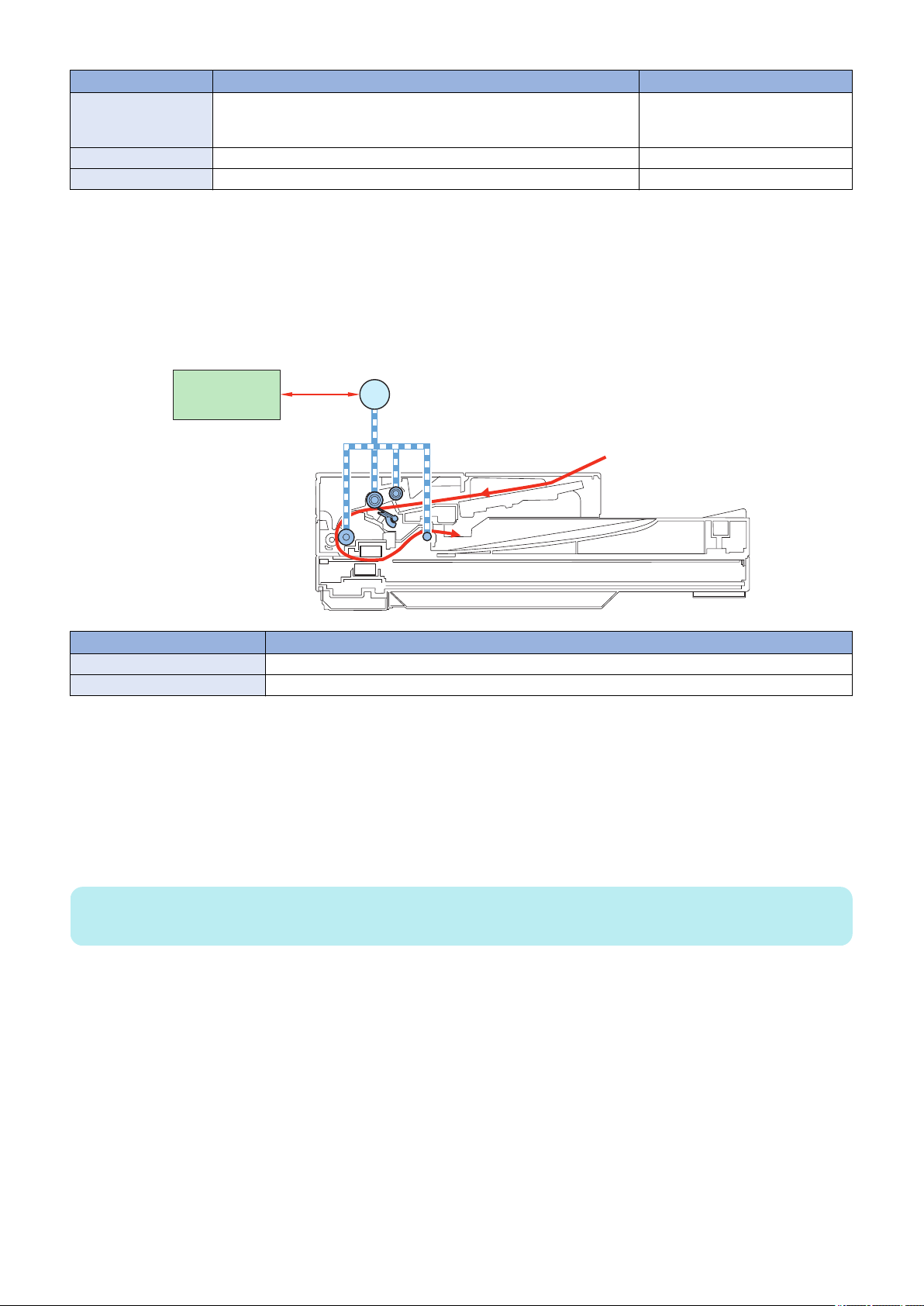
■ Drive Configuration
Description
When copy, fax, or scan is started, the ADF Motor (M11) is driven by a drive command from the Main Controller PCB.
The document which is placed face-up on the Original Tray is picked up and fed one sheet at a time in order from the top.
When the fed original passes over the Platen Glass, the image is read by the Contact Image Sensor (CIS), and then the original
is delivered face-down to the Document Delivery Assembly.
Symbol Name
M11 ADF Motor
MCON Main Controller PCB
* Simultaneous duplex scanning models only. (Reference: “Product Lineup” on page 5)
■ Original Detection
Overview
This machine has the following two types of original detection functions.
• Original Detection
• Original Edge Detection
NOTE:
This machine does not have a document size (original width) detection function.
Description
Original Detection
As the actuator is pushed up by placing an original on the Original Tray, the Document Sensor (SR9) is turned ON (light is
transmitted -> light is blocked) so that the presence of an original is detected.
Original Edge Detection
As the actuator is pushed up by the leading edge of the fed original, the Document End Sensor (SR10) is turned ON (light
is blocked -> light is transmitted) so that the leading edge of the original is detected.
In addition, when the trailing edge of the original passes the position of the actuator, the actuator returns to the original
position, which causes the Document End Sensor (SR10) to turn OFF (light is transmitted -> light is blocked) to detect the
trailing edge of the original.
Note that the original length that can be read by this machine is 400 mm and less; if an original longer than that is fed, it is
stopped due to jam. The original length is determined by the time required from when the Document End Sensor (SR10)
detects the original's leading edge to when it detects its trailing edge.
20

SR10
SR9
MCON
*
Symbol Name
SR9 Document Sensor
SR10 Document End Sensor
* Simultaneous duplex scanning models only. (Reference: “Product Lineup” on page 5)
■ Jam Detection
2. Technical Explanation (Device)
Execution Condition/Timing
When the power is turned ON or when the original is being read
Description
In the following cases, it is judged that an ADF jam has occurred.
• When the original is late in arriving the Document End Sensor or remains in the ADF while the original is being read
• When the Document End Sensor detects presence of paper when the power is turned ON (residual paper jam)
• When a document of 400 mm or more is detected
When a jam is detected, the reading operation stops and "Paper is jammed." is displayed on the screen of the Control Panel.
In the case of models equipped with the fax function (built-in speaker), a warning tone (beep sound) sounds when a jam is
detected.
The jam can be cleared by removing the jammed paper, opening and then closing the ADF Upper Cover, and placing the original
again.
21
 Loading...