

Canon D78-5152, LV-5110E, D78-5153 User Manual

SERVICE MANUAL
English Edition
LV-5110U/D78-5152
LV-5110E/D78-5153
By Portable Document Format
1
General
0
PREFACE
2
Repair
3
Adjustment
4
Troubleshooting
5
Parts Catalog
6
Electrical Diagrams
Return to Contents
DY8-1785-151 500


CANON Multimedia Projector
LV-5110U D78-5152
LV-5110E D78-5153
SERVICE
SMANUAL

Technical Documents
Application
This CD-ROM is issued by Canon Inc. for qualified persons to learn technical theory and product
repair. This CD-ROM covers all localities where the products are sold. For this reason, there
may be information in this CD-ROM that does not apply to the product sold in your locality.
The following paragraph does not apply to any countries where such provisions are
inconsistent with local law.
Trademarks
The product names and company names described in this CD-ROM are the registered
trademarks of the individual companies.
Copyright
Canon Inc. retains the copyright to all data contained on this CD-ROM.
Reproduction, publication (including on the World Wide Web) alteration, translation into another
language, or other use of the data in whole or part, contained on this CD-ROM without the
written consent of Canon Inc., is prohibited.
PDF Files
This CD-ROM contains PDF files created using Adobe®Acrobat®4.0J. PDF files can be viewed
using Adobe®Acrobat®Reader 4.0 or later.
Copyright © 2001 by Canon Inc.
CANON INC.
30-2 Shimomaruko 3-Chome, Ohta-ku,
Tokyo 146-8501, Japan
First published July, 2001

PREFACE
1. Service Manual Composition
This manual contains information on servicing the product. It has the following sections.
Part 1 General Information
Provides the basic information needed to understand the product.
(Operating instructions are not included. Refer to the product's instruction book if
necessary.)
Part 2 Repair Information
Provides information for disassembly, reassembly, and adjustment of the product, about
the tools required, and their application.
Part 3 Adjustment
Provides information for disassembly, reassembly, and adjustment of the product, about
the tools required, and their application.
Part 4 Troubleshooting
Part 5 Parts Catalog
Part 6 Electrical Diagrams
2. Model Differences
In this series of products, there are models suffixed “J”, “U”, and “E”. The only
differences between the models are cosmetic, mainly the designation and rating plates.
Internally, they are identical.
I
Main Marketing Area Japan North America Europe
Model Name
POWER PROJECTOR
MULTIMEDIA PROJECTOR MULTIMEDIA PROJECTOR
LV-5110J LV-5110U LV-5110E

II
3. Tools & Test Equipment
1) General Purpose Tools
2) Test Equipment (Local Purchase)
3) Other Equipment (Local Purchase)
4) Chart/Software (Attached with this manual)
Description Tool No. Remarks
Ball Driver, 2.0mm hex CY9-5002-000 Optical Parts Removal & Adjustment
Hex Key Set (w/2.0mm) CY9-5007-000 Optical Parts Removal & Adjustment
Driver, Ceramic Tip (1.8mm) CY9-5003-000 Electrical Adjustments
Driver, Slot (4.0mm) CY9-5004-000 Optical Parts Adjustment
Driver, Cross-point (#2) CY9-5005-000 Assembly & Disassembly
Description Specifications Remarks
Digital Multi-meter 1mV – 500V DC Electrical Adjustment
Video Signal Generator
Color Bars and Gray Scale
Electrical Adjustment
Computer Signal Generator Gray Scale Electrical Adjustment
Oscilloscope
100MHz response or over
Waveform checks
Description Specifications Remarks
Screen Over 40” All Adjustment
Personal Computer Windows 95 OS All Adjustment
Description Specifications Remarks
Monitor Tester XGA and SVGA Electrical Adjustment
Gray Scale Chart Bitmap Data Electrical Adjustment
Color Shading Correction Tool Ver. 2.0.2 White Uniformity Adjustment

CONTENTS
Page
Part 1: General Information
1. FEATURES.......................................................................................................1-1
1.1 Development objectives............................................................................1-1
1.2 Major Features..........................................................................................1-2
1.3 LV-5110 Features (Details).......................................................................1-3
2. LV-5110 SPECIFICATIONS .............................................................................1-5
2.1 Main unit ...................................................................................................1-5
2.2 Connectors ...............................................................................................1-6
2.3 Accessories ..............................................................................................1-6
2.4 Other specifications ..................................................................................1-6
3. NOMENCLATURE............................................................................................1-7
3.1 Main unit ...................................................................................................1-7
3.2 Top controls..............................................................................................1-8
3.3 Rear panel terminals.................................................................................1-9
3.4 Computer Input terminal ...........................................................................1-10
3.5 Control port connector ..............................................................................1-10
3.6 Remote control .........................................................................................1-11
3.7 Operating range........................................................................................1-12
4. COMMENTARY................................................................................................1-13
4.1 External appearance design.....................................................................1-13
4.2 Hybrid gamma correction..........................................................................1-13
4.3 Fan speed control.....................................................................................1-14
5. CONNECTING..................................................................................................1-15
5.1 Connection to the computer......................................................................1-15
5.2 Connecting to the video equipment ..........................................................1-16
6. SETTING-UP THE PROJECTOR.....................................................................1-17
6.1 Positioning the projector ...........................................................................1-17
6.2 Installation precautions.............................................................................1-17
7. SUPPORTED COMPUTER SYSTEM MODE ..................................................1-19
Part 2: Repair Information
1. SAFETY INSTRUCTIONS................................................................................2-1
2. CIRCUIT PROTECTIONS ................................................................................2-2
2.1 Fuse..........................................................................................................2-2
2.2 Thermal Switch.........................................................................................2-2
2.3 Warning Temperature and Power Failure Protection ...............................2-3
2.4 Air Filter Care and Cleaning .....................................................................2-3
3. MECHANICAL DISASSEMBLIES.....................................................................2-5
3.1 Cabinet Top Removal...............................................................................2-5
3.2 Cabinet Front and Speaker Removal .......................................................2-5
3.3 Main Board Removal ................................................................................2-6
3.4 Fuse Removal...........................................................................................2-6
3.5 AV and Component Board Removal.........................................................2-7
3.6 Line Filter Board Removal ........................................................................2-7
III

3.7 Lamp Ballast Unit Fan (FN905) Removal.................................................2-8
3.8 Power Board Removal..............................................................................2-8
3.9 Optical Unit and Fan (FN901) Removal....................................................2-9
3.10 Audio Amp. Board Removal ...................................................................2-9
3.11 Fans (FN902, FN903, FN904) Removal.................................................2-10
3.12 AC Inlet Ass’y Removal ..........................................................................2-10
4. OPTICAL PARTS DISASSEMBLIES................................................................2-11
4.1 Projection Lens Removal..........................................................................2-11
4.2 Optical Unit Top Removal.........................................................................2-11
4.3 Integrator Lens Ass’y Disassembly...........................................................2-12
4.4 Relay Lens Ass’y Disassembly.................................................................2-12
4.5 Polarized Glass-in Ass’y Disassembly......................................................2-13
4.6 Polarized Glass-out Ass’y Disassembly....................................................2-13
4.7 Locations and Directions ..........................................................................2-14
5. LCD PANEL/PRISM ASS’Y REPLACEMENT..................................................2-15
5.1 LCD Panel/Prism Ass’y Removal..............................................................2-15
5.2 Note on LCD Panel/Prism Ass’y Mounting ...............................................2-16
6. CLEANING........................................................................................................2-17
7. LAMP REPLACEMENT....................................................................................2-18
Part 3: Adjustment
1. BEFORE ADJUSTMENTS................................................................................3-1
1.1 Adjustments after Parts Replacement ......................................................3-2
1.2 Service Adjustment Menu Operation........................................................3-3
1.3 Service Conditions....................................................................................3-4
1.4 Service Adjustment Data Table ................................................................3-5
2. ELECTRICAL ADJUSTMENTS........................................................................3-7
2.1 Output Voltage Adjustment.......................................................................3-7
2.2 Fan Voltage Adjustment ...........................................................................3-7
2.3 PC-Offset Adjustment...............................................................................3-8
2.4 PC Gain Adjustment .................................................................................3-8
2.5 Component Gain Adjustment....................................................................3-9
2.6 AV Gain Adjustment .................................................................................3-10
2.7 NRS Adjustment .......................................................................................3-10
2.8 Signal Center Adjustment.........................................................................3-11
2.9 PC/AV Gamma Off Adjustment ................................................................3-11
2.10 PC/AV-Video Adjustment-1 ....................................................................3-12
2.11 PC/AV-Video Adjustment-2 ....................................................................3-13
2.12 S/H Clock Adjustment.............................................................................3-13
2.13 Common Center Adjustment ..................................................................3-14
2.14 White Balance Adjustment......................................................................3-14
2.15 Black Balance Adjustment......................................................................3-15
2.16 Note on White Uniformity Adjustment.....................................................3-15
3. OPTICAL ADJUSTMENTS...............................................................................3-16
3.1 Contrast Adujstment .................................................................................3-16
3.2 Integrator Lens Adujstment.......................................................................3-17
3.3 Relay Lens Adjustment.............................................................................3-19
4. TEST POINTS AND LOCATIONS....................................................................3-20
IV

Part 4: Troubleshooting
1. TROUBLESHOOTING......................................................................................4-1
1.1 No Power..................................................................................................4-1
1.2 No Sound..................................................................................................4-6
1.3 No Picture.................................................................................................4-7
2. CONTROL PORT FUNCTIONS .......................................................................4-9
2.1 System Control & I/O Port Functions........................................................4-9
3. WAVEFORMS ..................................................................................................4-11
4. IC BLOCK DIAGRAMS.....................................................................................4-14
Part 5: Parts Catalog
Part 6: Electrical Diagrams
1. PARTS DESCRIPTION AND READING IN SCHEMATIC DIAGRAM..............6-1
2. PIN DESCRIPTION OF DIODE, TRANSISTOR AND IC..................................6-3
Circuit Block Diagram........................................................................................A1
Power Supply Lines ..........................................................................................A2
Schematic Diagrams.........................................................................................A3
Printed Wiring Board Diagrams.........................................................................A10
V


Part 1
General
Information


1. FEATURES
1.1 Development objectives
With its sights firmly fixed on the SOHO-HOME market, Canon introduced the LV-
5100 B5 file size microportable* multimedia projector to consumers last year.
Equipped with a 0.7-inch liquid crystal panel, this LCD projector has been offering a
more compact size and greater portability at an even lower cost than before. In contrast,
Canon's competitors in this product range have brought out projectors with the same
high brightness to be found in liquid crystal projectors featuring 1.3-inch and 0.9-inch
liquid crystal panels.
Now following on the heels of the LV-5100 as its successor is the LV-5110 multimedia
projector. It employs a high-brightness lamp, and its aim is to maintain the company's
competitive edge in this product field while further opening up the market.
*Microportable: Defined by Canon to mean an LCD projector that weighs less than 3kg.
Part 1: General Information
1-1
Fig. 1-1 LV-5110

1.2 Major Features
● Compact, lightweight 2.7kg/B5 file size micro-portable type
Real SVGA compatible, class-leading 850 ANSI lumen output
● Supports HDTV&DVD component input
Beautiful image reproduction with minimal burring of color
● Equiped with Digital Keystone function
Smoothly corrects for "keystone" effect caused by projector tilt, giving a square image
with up to 15 degrees tilt.
● Plug and Play: Simply plug in computer or AV components and start - no adjustments
required.
1) Multiscan System automatically detects PC vertical and horizontal scan
frequencies
2) Video color system: Automatically detects system (NTSC/PAL; SECAM/NTSC4.43)
PAL-M/PAL-N can be selected from menu bar)
3) Tracking: Auto Imaging function automatically tracks and optimally positions
image
4) Graphic User Interface (GUI): The graphic user interface simplifies image
adjustments in varying environments.
5) Six Language support: English, French, German, Italian, Spanish and Japanese
are supported
6) Wireless Remote Control: Remote control has mouse control functions
● Temperature-sensing Real Time Fan Control: Unobtrusive sound level for conferences
● Gamma Correction: Gives high quality reproduction of gradation
Part 1: General Information
1-2

1.3 LV-5110 Features (Details)
● Brightest in the SVGA Micro Projector class - 850 ANSI Lumens
1) Large screen presentation even in brightly lit conference rooms
2) 132W UHP short arc lamp for bright images with great color balance
● Real projection SVG (800 x 600 dot) Digital compression XGA/SXGA high-definition
projection *
0.7" LCD Panels used (for the first time)
● Supports input from HDTV&DVD components
Color defference signal (Y, Pb/Cb, Pr/Cr) input reproduces the images with minimal
burring of color.
* Composite (Video) input is common to the Brightness (Y) input.
● Digital Keystone distortion compensation
When the projected image surface and the projector are offset, the image has a
trapezoidal shape, but this can be smoothly compensated with offsets up to 15
degrees.
A simple operation gives a square image without adjusting the height of the projector.
● Gamma Correction
To avoid washed-out whites and murky blacks the user can control the middle
brightness.
● Plug and Play: Simply plug in computer or AV equipments and start - no adjustments
required.
● Power Management: improves lamp life
After a predetermined time (5' 30") with no input signal, the lamp is turned off. When
a signal is input, it turns back on.
● Simple wireless remote control
1) Supports all remote functions
2) P-Timer button supplies presentation elapsed time
3) Functions as the mouse control for connected PC
● Manual zoom and focus controls included
● Digital zoom enlarges any selected part of the presentation image
● Cues up the next screen without pausing or projecting an unnecessary operation
screen. (Freeze function)
● The image can be turned off without turning the power off and immediately turned back
on - Image shut-off function.
● Noise is cut in the absence of a signal - Blue Back function.
Part 1: General Information
1-3

● Impressive image size - up to 200 inches.
● Reverse image function allows the unit to be suspended from the ceiling or used as a
rear-screen projector.
● Reduced lamp problems (Replace Lamp Indication)
1) The replace lamp indicator shows when it is time for a change.
2) Lamp replacement by the user is simple.
● The design emphasizes the lens, as you would expect from a Canon product.
* With digital compression projection, some information is lost.
XGA: 1024 x 768 dot → 800 x 600 dot when digitally compressed
SXGA: 1280 x 1024 dot → 750 x 600 dot when digitally compressed
Part 1: General Information
1-4

Part 1: General Information
1-5
2. LV-5110 SPECIFICATIONS
2.1 Main unit
1. Type: Micro-portable LCD Projector
2. LCD panel: 0.7" polysilicon active matrix TFT x 3
4:3 aspect ratio
3. Number of pixels: 480,000 pixels (800 H x 600 V) x 3
4. Resolution of display supported: SXGA & XGA (compression)/SVGA/VGA
5. Light source: 132W UHP lamp
6. Brightness: 850 ANSI lumens
7. Illuminance ratio at
edges of image field: 90%
8. Contrast ratio: 300:1
9. Horizontal resolution: 500 TV lines
10. Projection lens: 28 to 33.6mm, 1:2.0 to 2.3, x1.2
11. Lens shifting (U/D ratio): 12:1
12. Elevation adjustment: UP by 7.5˚
13. Size of projection image(in.)/ 36" (1.4m), 60" (2.4m), 100" (4.0m), 150" (6.0m),
projection distance(m): 200" (8.0m) in WIDE mode
30" (1.4m), 50" (2.4m), 83" (4.0m), 125" (6.0m), 167"
(8.0m) in TELE mode
14. Digital keystone distortion
compensation angle: ±15˚
15. Noise: 39dB (normal temperature)
16. Color system: NTSC, PAL, SECAM, NTSC4.43, PAL-M, PAL-N
17. Computer supported: IBM PC or compatible, Macintosh, PC98, Workstations
Note: Some workstations are not supported.

18. Scanning frequency: 15KHz to 80KHz for horizontal sync.
50Hz to 100Hz for vertical sync.
Up to 100MHz for dot clock
19. Audio output: 1W monaural
20. Built-in speaker: 40mm x 30mm (1.57" x 1.18"), x 1
21. Rated supply voltage: 100V AC, 50 / 60Hz (Japan)
100 to 120V AC / 200 to 240V AC, 50 / 60Hz (overseas)
22. Power consumption: 210W
23. Operating temperature: 5 to 35˚C (41 to 91˚F)
24. Storage temperature: –10 to 60˚C (14 to 140˚F)
25. Dimensions (W x H x D) 189mm x 75.5mm x 310.8mm (7.44" x 2.97" x 12.24")
(Not including adjustment feet)
189mm x 90.5mm x 310.8mm (7.44" x 3.56" x 12.24")
(Including adjustable feet)
26. Net Weight: 2.7Kg (5.95 lbs)
2.2 Connectors
1. Computer input
Signal input: HDB 15-pin x 1
Audio input: Mini stereo jack x 1
Control port: Mini DIN 8-pin x 1
2. Audio/Video input
Video input: Mini DIN 4-pin x 1 (S-Video)
RCA type x 3 (Video/Y, Pb/Cb, Pr/Cr)
Audio input: Mini stereo jack x 1
3. Audio output: Mini stereo jack x 1
2.3 Accessories
1. Remote Control Transmitter with two AA alkaline batteries
2. VGA Cable
3. Control Cable for PS/2 port
4. Lens Cover
5. Carry Bag
6. AC Power Cord
7. Plug Adapter (Japan model only)
8. Warranty Card
9. Owner's Manual
2.4 Other specifications
Service life of lamp: Approx. 1000 hours
Part 1: General Information
1-6

3. NOMENCLATURE
3.1 Main unit
Part 1: General Information
1-7
Power Cord Connector
Projection Lens
Speaker
Infrared Remote Receiver
Lens Cover
Air Intake Vent
Zoom Ring
Focus Ring
Foot Lock Latch
Exhaust Vent
Air Intake Vent
Air Intake Vent
Lamp Cover
Air Filter
Adjustable Foot
Terminals and Connectors
Fig. 1-2

3.2 Top controls
Part 1: General Information
1-8
WIDE
TELE
POWER MENU
MODENORMAL
LAMP
REPLACE
WARNING
TEMP.
READY
LAMP
FOCUS RING
Turn this ring to adjust the
projected picture focus.
WARNING TEMP. INDICATOR
This indicator flashes red when internal
projector temperature is too high.
MENU BUTTON
Use to open or close
the Menu operation.
ZOOM RING
Turn this ring to adjust the
projected picture size.
READY INDICATOR
This indicator lights green when
the projector is ready to be turn on.
And it flashes green in Power
Management mode.
LAMP INDICATOR
This indicator is dim when
the projector is turn on.
And bright when the projector
is stand-by mode.
LAMP REPLACE INDICATOR
This indicator turns to yellow when
the life of the projection lamp draws
to an end.
POINT BUTTON
Use to select an item of adjust
the value in the menu.
It is also used to pan the image
in Digital Zoom mode.
MODE BUTTON
Use to select input source
either Computer or Video.
SELECT BUTTON
Used to execute the item selected.
It is also used to expand the image
in Digital Zoom mode.
NORMAL BUTTON
Used to rest to normal picture
adjustment preset by factory.
POWER ON-OFF BUTTON
Used to turn on the projector on
or off.
Fig. 1-3

3.3 Rear panel terminals
Part 1: General Information
1-9
COMPUTER IN
S – VIDEO
COMPUTER
CONTROL PORT
RESET
AUDIO
IN
AV
Y – Pb/Cb – Pr/Cr
AUDIO OUT
VIDEO
RESET BUTTON
The micro processor may
malfunction and need to rest.
This can be done by pressing
the Reset button with a pen,
which will shut down and
restart the projector.
AUDUO OUTPUT
Mini stereo Jack
Connect the external audio
amplifier to this terminal.
COMPUTER INPUT
HDB 15-pin type
Connect the computer output
signal to this terminal.
CONTROL PORT
Mini DIN 8-pin type
When controlling the computer
with the Remote Control of this
projector, connect the mouse
port of the computer to this
terminal.
COMPUTER AUDIO INPUT
Mini stereo jack
Connect the audio output
signal from the computer
to this terminal
AUDIO INPUT
Mini stereo jack
Connect the audio output
from the video equipment
to this terminal.
S-VIDEO INPUT
Mini DIN 4-pin type
Connect the S-Video output
from the video equipment
to this terminal.
VIDEO INPUTS
(Y/VIDEO, Pb/Cb, Pr/Cr)
RCA type jacks
Connect the composite video
output signal to the Y/Video
jack or connect the component
Y output signals to the Y/Video,
Pb/Cb and Pr/Cr jacks.
Fig. 1-4

3.4 Computer Input terminal
Connect the display output terminal of the computer to this terminal with the VGA
Cable (attached).
When connecting the Macintosh computer, the MAC Adapter (optional) is required.
3.5 Control port connector
When controlling the computer with the remote control of this projector, connect the
mouse port of the personal computer to this terminal.
This terminal does not adapt the PC98 type mouse port.
Part 1: General Information
1-10
5
1
2
34
10
9 678
15
14 13
1112
Red Input
Ground (Horiz.sync.)
Green Input
Sense 2
Blue Input
Ground (Red)
Ground (Green)
Ground (Blue)
1
5
2
4
3
6
7
8
No Connect
Horiz. sync.
Ground (Vert.sync.)
Sense 1
Sense 0
Vert. sync.
Reserved
9
13
10
12
11
14
15
Fig. 1-5
1
2
3
4
5
8 7 6
-----
CLK
DATA
GND
-----
-----
GND
-----
RXD
-----
-----
GND
RTS
TXD
GND
GND
-----
ADB
-----
GND
-----
-----
-----
GND
PS/2 Serial ADB
1
2
3
4
5
6
7
8
Fig. 1-6

3.6 Remote control
Part 1: General Information
1-11
VOLUME
POWER
D.ZOOM
KEYSTONE
VIDEO
MENU
MUTE
P-TIMER
NO SHOW
FREEZE
AUTO IMAGE
NORMAL
COMPUTER
ON
ALL OFF
D.ZOOM BUTTON
KEYSTONE BUTTON
Used to correct the keystone
distortion.
MUTE BUTTON
MENU BUTTON
POINT BUTTON
Used to move a pointer
on the menu, to adjust the
item, or to pan the image
in Digital Zoom mode.
SELECT BUTTON
Used to execute the item
selected or to expand the image
in Digital Zoom mode.
NO SHOW BUTTON
Used to turn the picture into
black image.
AUTO IMAGE BUTTON
Used to operate Auto Image function.
POWER BUTTON
VOLUME BUTTON
COMPUTER BUTTON
Use to select Computer input
source.
VIDEO BUTTON
Use to select Video source.
RIGHT CLICK BUTTON
Use to compress the image in
Digital Zoom mode.
It is also used as a PC mouse
in Wireless Mouse operation.
P-TIMER BUTTON
Used to operate P-timer function.
FREEZE BUTTON
NORMAL BUTTON
Used to reset to normal picture
position preset by factory.
ALL-OFF SWITCH
When using the Remote Control
Unit, turn this switch to "ON".
And turn it to "ALL OFF" when
it is not used.
Fig. 1-7
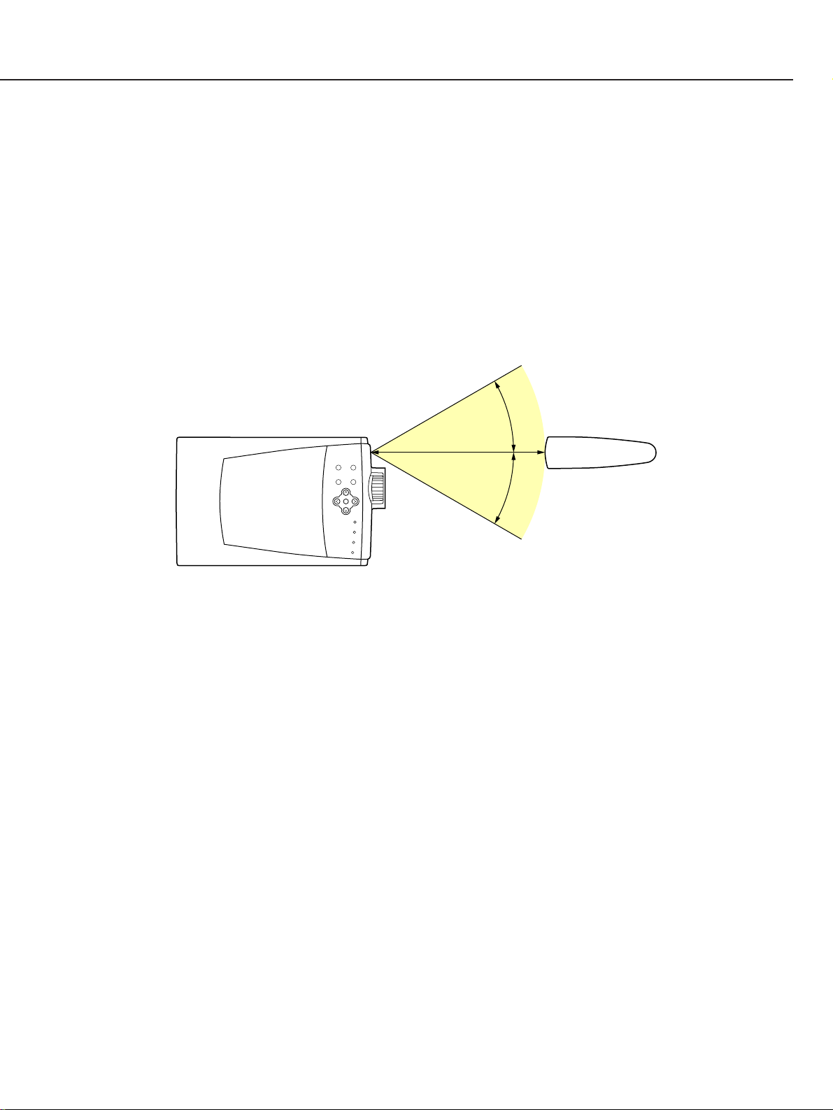
3.7 Operating range
Point the remote control toward the projector (receiver's window) when pressing the
buttons.
Maximum operating range for the remote control is approximately 5m (16.4') and 60˚ in
front of the projector.
Precautions
• Prevent the direct sunlight or strong light from lighting apparatus from striking the
infrared remote receiver on the projector.
• Do not look into the laser pointer exit or point it at others.
• Do not dismantle the remote control.
Part 1: General Information
1-12
5m
30˚
30˚
Fig. 1-8

4. COMMENTARY
4.1 External appearance design
This product follows the same design concept and coloring as the earlier models, LV7325/LV-7320 to establish a unified image for Canon Multimedia Projectors. Some of
the major design points, which are basically the same as the other Canon Multimedia
Projectors, are outlined below.
● External Styling
The body is designed with subtle curves and the coloring and semi-transparent body
panels follow the lead of the LV-7300 series. Indications of the excellent lens
performance are printed around the lens to convey an impression of high picture
quality.
● Operating Keys
The operation and cursor key layout is a simple, intuitive layout with grouping to
insure ease of use.
● Coloring
The body of the projector is colored glacial blue. The front of the unit, with an
appearance fittimg a product from an optical equipment manufacturer, has an
aluminum lens ring and is colored arctic silver. The overall effect is to emphasize the
lens and evoke a sophisticated image.
The operating keys are a special "mercury silver" color that is easy to see in dim light
and also serves as a design accent point.
4.2 Hybrid gamma correction
Hybrid gamma correction is a new feature. It combines digital gamma correction and
analog gamma correction, and takes advantage of the characteristics* of both. Using the
on-screen menu, the user can take advantage of this new feature to control image
gradation.
* Analog gamma correction: analogue correction is applied to the non-linear analog
circuit. In analog correction transitions between gradations
are smooth.
* Digital gamma correction: Correction is applied through digital processing of the X/Y
gamma curve. Using a digital signal, varying the
characteristics curve, for example, is simple. Because
digital processing is involved, however, transitions between
gradations can be abrupt.
Part 1: General Information
1-13

4.3 Fan speed control
A new feature of this projector is Real Time Fan Control. Temperature sensors control
the fan to reduce the fan noise level to an unobtrusive level (39dB) during normal
operation.
There are two temperature sensors, sensor 1 measuring ambient room temperature
and sensor 2 measuring the temperature in the area of the LCD panels. The outputs of
the sensors are sent to the CPU, which then controls the voltage applied to the fan as
outlined below.
1.If the internal temperature rises, the fan voltage is changed as shown in the figure
below.
But, if the internal temperature falls, the fan voltage remains unchanged for five
minutes, then is changed
The fan voltage is determined by the higher of the two sensor temperatures.
2.If the temperature sensed by sensor 1 exceeds 51˚C, or the temperature sensed by
sensor 2 exceeds 57˚C, the lamp is extinguished. In this case, the main power switch
must be turned off and then back on to resume operation.
3.The fan will continue to run for a maximum of 90 seconds after the power switch is
turned off.
4.If the CPU receives no response from a sensor, it determines that the sensor is
missing or broken and immediately shuts down the projector.
5.In Service Mode (when operating at high altitude) the fan operates at maximum
voltage regardless of room temperature.
Part 1: General Information
1-14
Fan Drive Voltage
13V
12V
11V
10V
9V
27
ûC
41ûC
47ûC
Room Temperature:
Sensor 1:
Sensor 2:
35
ûC 37ûC
49ûC 51ûC
55ûC 57ûC
Unit shutdown Temperature
Fan Noise: 39dB Fan Noise: 43dB
Intake Fan
Exhaust Fan
Fig. 1-9

5. CONNECTING
5.1 Connection to the computer
Part 1: General Information
1-15
COMPUTER IN
S – VIDEO
COMPUTER
CONTROL PORT
RESET
AUDIO
IN
AV
Y – Pb/Cb – Pr/Cr
AUDIO OUT
VIDEO
13" MODE (640 x 480)
16" MODE (832 x 624)
19" MODE (1024 x 768)
OFFON ON
ON ON
ON ON
OFF OFF OFF
OFFOFF OFF OFF
OFF OFF OFF OFF
1 2 3 4 5 6
OFF OFFON ONON ON21" MODE (1152 x 870)
ON
1
DIP
2 3 4 5 6
ON
OFF
IBM-compatible computers or Macintosh computers (VGA/SVGA/XGA/SXGA)
VGA Cable
(Attached)
Monitor Output
Desktop type Laptop type
Speaker (Stereo)
Audio Amplifier
Control Cable
for Serial Port
(Optional)
Serial Port PS/2 Port Audio Output
Audio Input
CONTROL PORT
AUDIO OUT
COMPUTER AUDIO IN
COMPUTER IN
ADB Port
Control Cable
for PS/2 Port
(Attached)
Control Cable
for ADB Port
(Optional)
Terminal Terminal
Audio Cable
Mini Stereo type
(Not supplied)
Audio Cable
Mini Stereo type
(Not supplied)
Use one of these Control
Cables corresponding
with the terminal of your
computer.
Set the switches as shown in the table below depending on the Display
Resolution that you want to use before you turn-on the projector and computer.
MAC Adapter
MAC Adapter
(Optional)
Set the slide
switches following
the chart bellow.
Terminal
Fig. 1-10

5.2 Connecting to the video equipment
Part 1: General Information
1-16
COMPUTER IN
S — VIDEO
COMPUTER
CONTROL PORT
RESET
AUDIO
IN
AV
Y — Pb/Cb — Pr/Cr
AUDIO OUT
VIDEO
Video Cable
(Not supplied)
S-VIDEO Output
Audio Input
Audio Output
Y Pb/Cb Pr/Cr R L
AV AUDIO IN
S-VIDEO
Y-Pb/Cb-Pr/Cr
VIDEO
AUDIO OUT
Composite
Video Output
Component
Video Output
Video Cassette Recorder Video Disc Player
Video Source (example)
Component video output equipment
(DVD Player, HDTV, etc.)
S-Vdeo Cable
(Not supplied)
Audio Cable
RCA-Mini Stereo Type
(Not supplied)
Audio Cable
Mini Stereo type
(Not supplied)
Speaker (Stereo)
Audio Amplifier
When several display signals are input,
the projector assigns priority in this order:
(1) Y, Pb/Cb, Pr/Cr, (2) S-Video, (3) Video.
If the desired input is not selected
automatically, use the video input menu
to select it.
Fig. 1-11

6. SETTING-UP THE PROJECTOR
6.1 Positioning the projector
This projector is designed to project on a flat projection surface.
The projector can be focused from 1.4m (4.6') to 8.0m (26.3').
Refer to the figure below to adjust the screen size.
6.2 Installation precautions
1) Temperature of air discharged from exhaust vent
Hot air is discharged from the exhaust vent. Do not put the object in the way of this
hot air.
2) Installation site
Do not install the projector in humid or duty locations, or locations subject to a lot of
oil mist or cigarette smoke. Doing so may cause dirt to adhere to the lenses, mirrors
and other optical parts, resulting in impaired image quality. Also, do not install the
projector in high- or low-temperature locations.
3) Operating temperature range: 5˚C to 35˚C
4) Storage temperature range: –10˚C to 60˚C
5) Condensation
Do not move the projector suddenly from a low-temperature location to a hightemperature location, or suddenly raise the room temperature. Doing so can cause
moisture in the air to condense on the lenses and mirrors of the projector, resulting
Part 1: General Information
1-17
H1
H2
200”
167”
150”
125”
100”
83”
60”
50”
36”
8.0m
6.0m
4.0m
2.4m
1.4m
30”
WIDE END
TELE END
Screen Size
(W x H) mm
Height (H1)
30”
Height (H2)
610 x 457
422mm
35mm
60”
1219 x 914
844mm
70mm
100”
2032 x 1524
1407mm
117mm
150”
3048 x 2286
2110mm
176mm
200”
4064 x 3048
2814mm
234mm
Fig. 1-12

Part 1: General Information
1-18
in blurred images.
6) Screen and room brightness
Do not install the projector where sunlight or lighting directly strikes on the screen. If
sunlight or light from lighting strikes on the screen, image will appear whitish and
difficult-to-view.
 Loading...